
Self Standing Mats of Blended Polyaniline Produced by Electrospinning

 ,
,  ,
,  , , , and
Abstract
:1. Introduction
2. Materials and Methods
2.1. Nanofibers Fabrication
2.2. Characterization
3. Results and Discussion
4. Conclusions
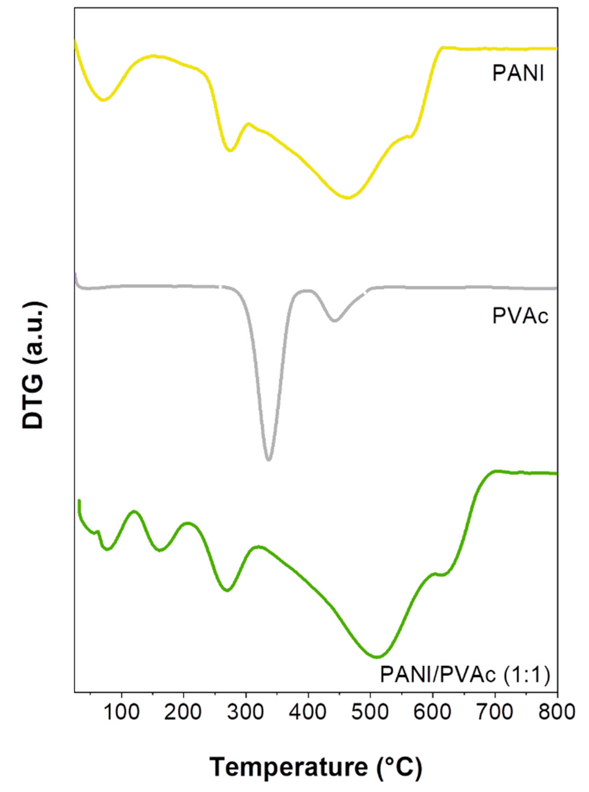
- PVAc and PMMA were used to improve the electrospinning of PANI. Copolymers endowed samples with different morphologies but similar thermal stability;
- High content of doped PANI were used, thus preserving its main electrical characteristic even in a blended form;
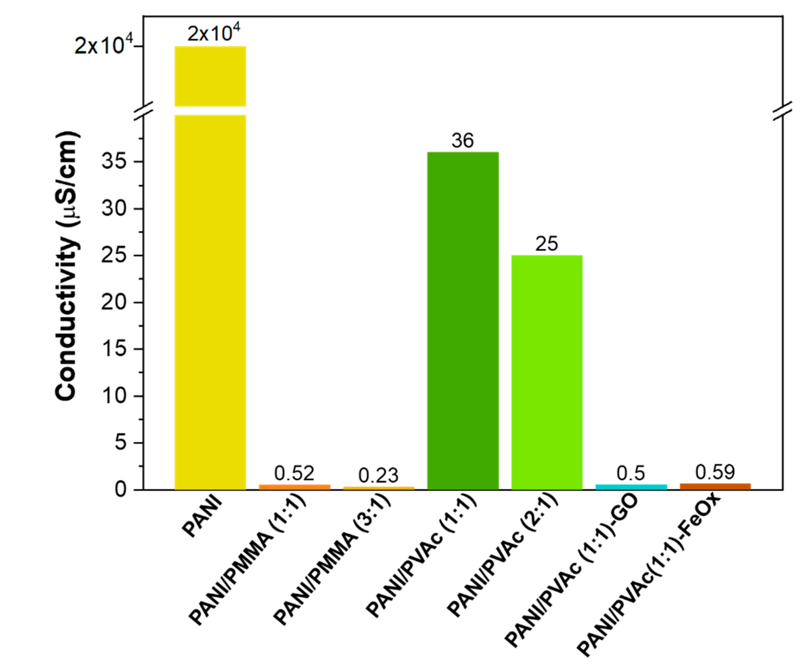
- Mats obtained with PMMA showed an electrical conductivity value two orders of magnitude lower than the sample obtained with PVAc;
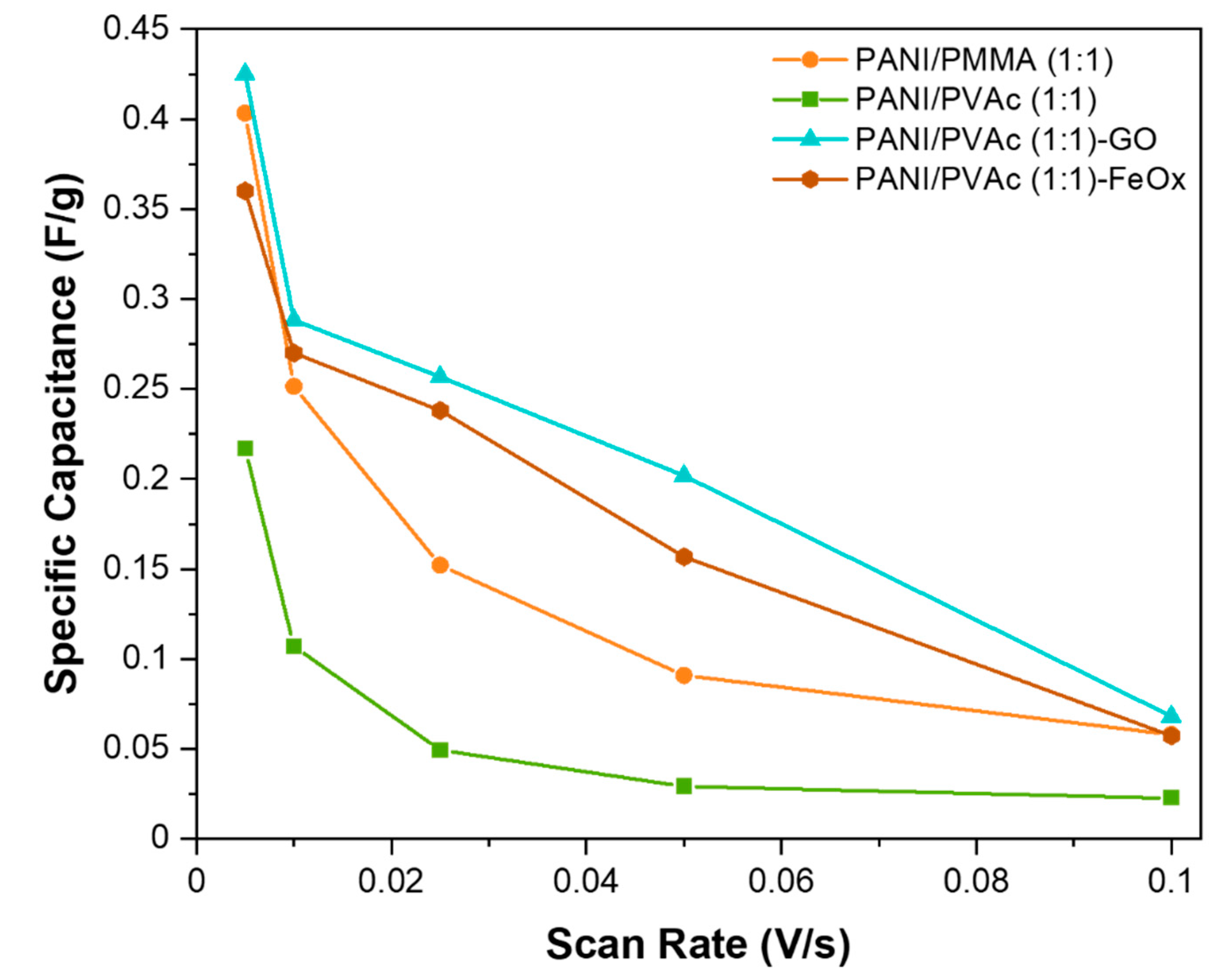
- Better capacitive performance of the PANI/PVAc sample was also observed with respect to the PMMA system;
- By increasing the copolymer quantity, a significant decrease in conductivity was observed. A similar trend was detected also for the specific electrical capacity, even if in a less amplified way;
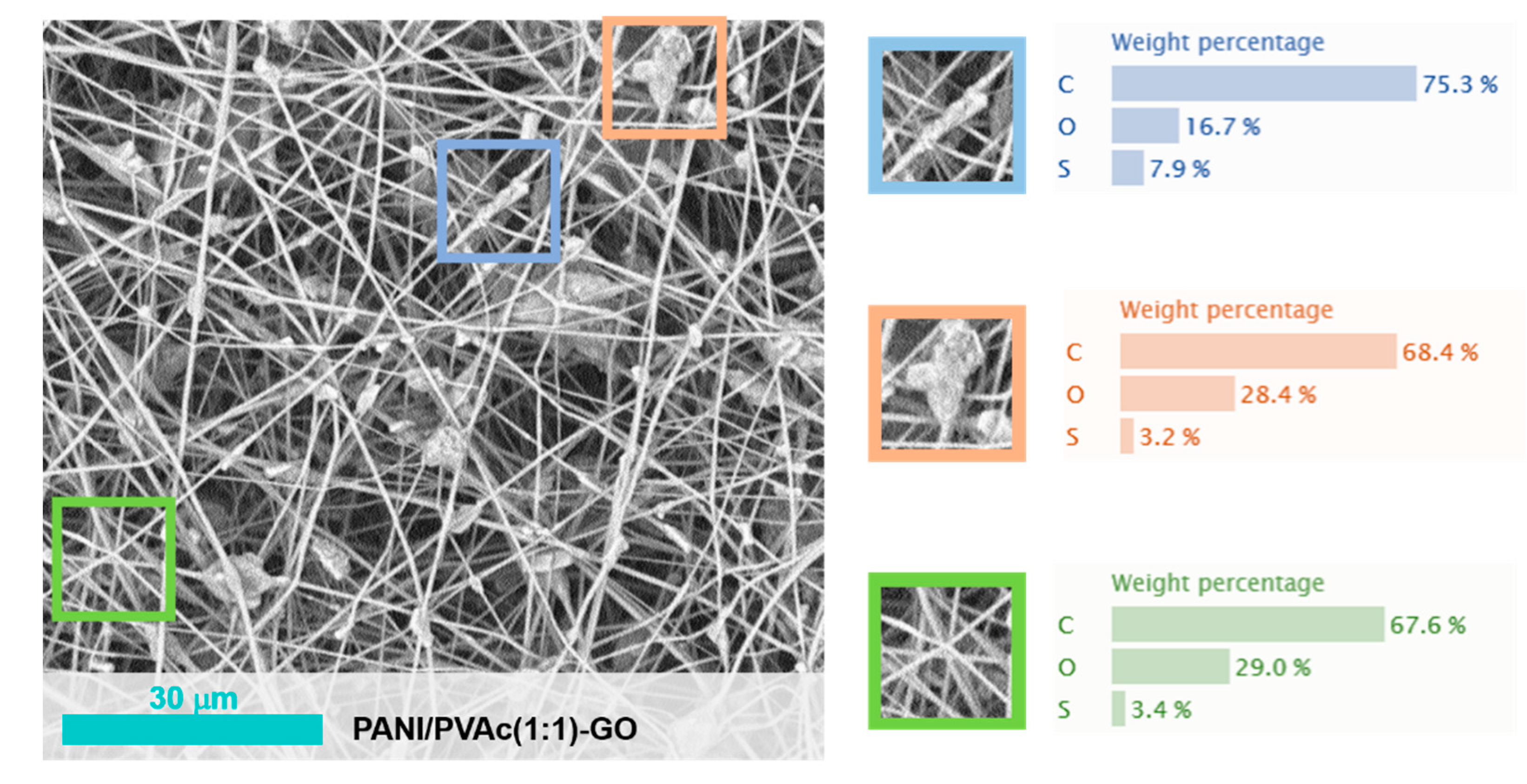
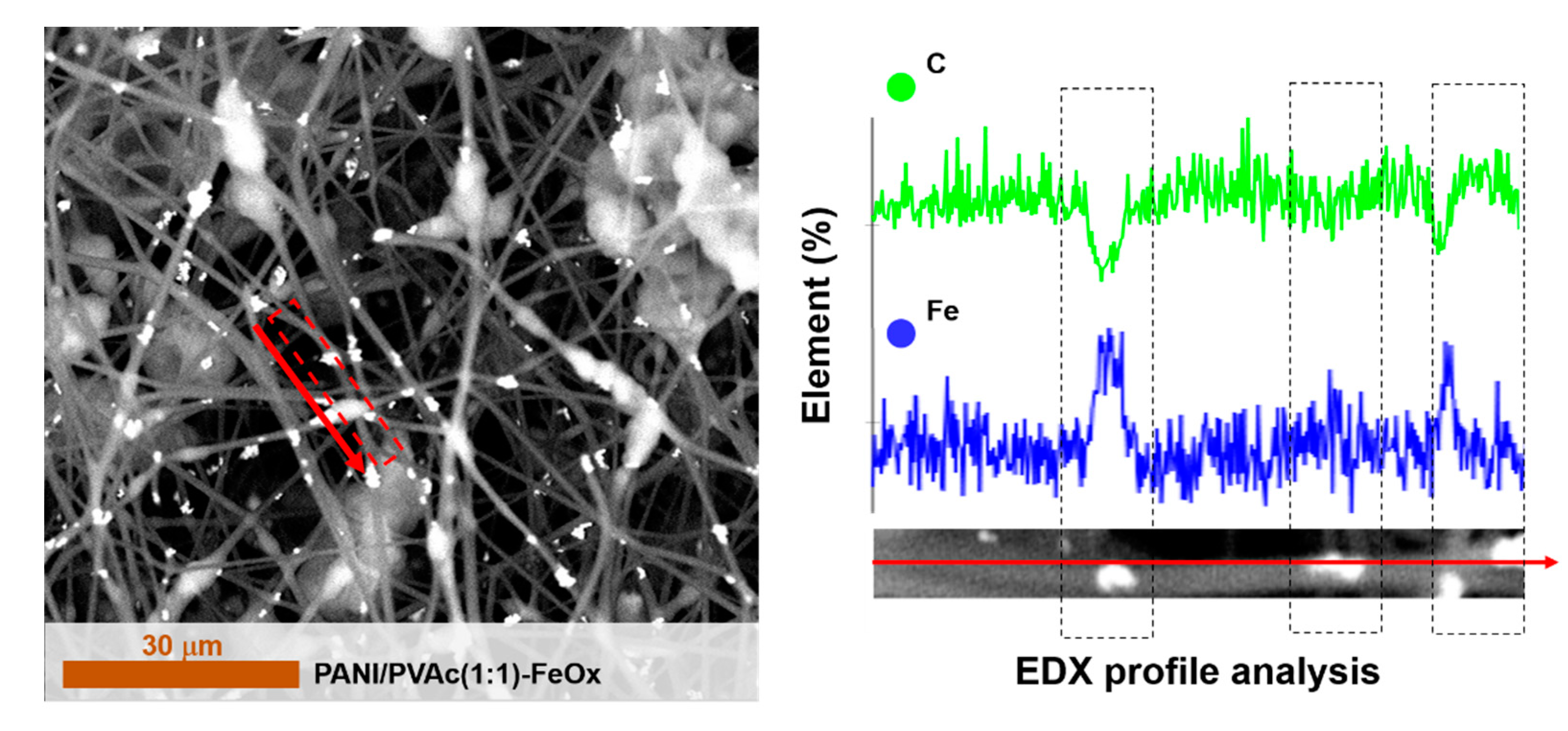
- The addition of graphene and iron oxides was found to decrease mats conductivity.
- Finally, PANI/PVAc system appears to be the most promising sample. Notwithstanding these preliminary results, many efforts should be further devoted to adjust the experimental parameters of the electrospinning procedure in order to obtain a PANI/PVAc nanocomposite, optimally doped with oxide particles and characterized by improved morphology, electrical properties and performances.
Supplementary Materials
Author Contributions
Funding
Acknowledgments
Conflicts of Interest
References
- Xue, J.; Wu, T.; Dai, Y.; Xia, Y. Electrospinning and electrospun nanofibers: Methods, materials, and applications. Chem. Rev. 2019, 119, 5298–5415. [Google Scholar] [CrossRef]
- Malara, A.; Frontera, P.; Bonaccorsi, L.; Antonucci, P.L. Hybrid zeolite SAPO-34 fibres made by electrospinning. Materials 2018, 11, 2555. [Google Scholar] [CrossRef] [Green Version]
- Malara, A.; Paone, E.; Bonaccorsi, L.; Mauriello, F.; Macario, A.; Frontera, P.P. Pd/Fe3O4 nanofibers for the catalytic conversion of lignin-derived benzyl phenyl ether under transfer hydrogenolysis conditions. Catalysts 2020, 10, 20. [Google Scholar] [CrossRef] [Green Version]
- Freni, A.; Calabrese, L.; Malara, A.; Frontera, P.; Bonaccorsi, L. Silica gel microfibres by electrospinning for adsorption chillers. Energy 2019, 187, 115971. [Google Scholar] [CrossRef]
- Bonaccorsi, L.; Fotia, A.; Malara, A.; Frontera, P. Advanced adsorbent materials for waste energy recovery. Energies 2020, 13, 4299. [Google Scholar] [CrossRef]
- Frontera, P.; Kumita, M.; Malara, A.; Nishizawa, J.; Bonaccorsi, L. Manufacturing and assessment of electrospun PVP/TEOS microfibres for adsorptive heat transformers. Coatings 2019, 9, 443. [Google Scholar] [CrossRef] [Green Version]
- Aruna, S.T.; Balaji, L.S.; Kumar, S.S.; Prakash, B.S. Electrospinning in solid oxide fuel cells—A review. Renew. Sustain. Energy Rev. 2017, 67, 673–682. [Google Scholar] [CrossRef]
- Malara, A.; Pantò, F.; Santangelo, S.; Antonucci, P.L.; Fiore, M.; Longoni, G.; Ruffo, R.; Frontera, P. Comparative life cycle assessment of Fe2O3-based fibers as anode materials for sodium-ion batteries. Environ. Dev. Sustain. 2020. [Google Scholar] [CrossRef]
- Ferrández-Rives, M.; Beltrán-Osuna, Á.A.; Gómez-Tejedor, J.A.; Ribelles, J.L.G. Electrospun PVA/bentonite nanocomposites mats for drug delivery. Materials 2017, 10, 1448. [Google Scholar] [CrossRef] [Green Version]
- Ge, J.C.; Kim, J.Y.; Yoon, S.K.; Choi, N.J. Fabrication of low-cost and high-performance coal fly ash nanofibrous membranes via electrospinning for the control of harmful substances. Fuel 2019, 237, 236–244. [Google Scholar] [CrossRef]
- Haider, A.; Haider, S.; Kang, I.-K. A comprehensive review summarizing the effect of electrospinning parameters and potential applications of nanofibers in biomedical and biotechnology. Arab. J. Chem. 2018, 11, 1165–1188. [Google Scholar] [CrossRef]
- Pereao, O.K.; Bode-Aluko, C.; Ndayambaje, G.; Fatoba, O.; Petrik, L.F. Electrospinning: Polymer nanofibre adsorbent applications for metal ion removal. J. Polym. Environ. 2017, 25, 1175–1189. [Google Scholar] [CrossRef]
- Frontera, P.; Malara, A.; Stelitano, S.; Leonardi, S.G.; Bonavita, A.; Fazio, E.; Antonucci, P.; Neri, G.; Neri, F.; Santangelo, S. Characterisation and H2O2 sensing properties of TiO2-CNTs/Pt electro-catalysts. Mater. Chem. Phys. 2016, 170, 129–137. [Google Scholar] [CrossRef]
- Liang, J.; Zhao, H.; Yue, L.; Fan, G.; Li, T.; Lu, S.; Chen, G.; Gao, S.; Asiri, A.M.; Sun, X. Recent advances in electrospun nanofibers for supercapacitors. J. Mater. Chem. A 2020, 8, 16747–16789. [Google Scholar] [CrossRef]
- Busacca, C.; Donato, A.; Faro, M.L.; Malara, A.; Neri, G.; Trocino, S. CO gas sensing performance of electrospun Co3O4 nanostructures at low operating temperature. Sens. Actuators B Chem. 2020, 303, 127193. [Google Scholar] [CrossRef]
- Yanılmaz, M.; Sarac, A.S. A review: Effect of conductive polymers on the conductivities of electrospun mats. Text. Res. J. 2014, 84, 1325–1342. [Google Scholar] [CrossRef]
- Tomczykowa, M.; Plonska-Brzezinska, M.E. Conducting polymers, hydrogels and their composites: Preparation, properties and bioapplications. Polymer 2019, 11, 350. [Google Scholar] [CrossRef] [Green Version]
- Nguyen, D.N.; Yoon, H. Recent advances in nanostructured conducting polymers: From synthesis to practical applications. Polymer 2016, 8, 118. [Google Scholar] [CrossRef]
- Kausar, A. Overview on conducting polymer in energy storage and energy conversion system. J. Macromol. Sci. Part A 2017, 54, 640–653. [Google Scholar] [CrossRef]
- Bavatharani, C.; Muthusankar, E.; Wabaidur, S.M.; Alothman, Z.A.; Alsheetan, K.M.; AL-Anazy, M.M.; Ragupathy, D. Electrospinning technique for production of polyaniline nanocomposites/nanofibres for multi-functional applications: A review. Synth. Met. 2021, 271, 116609. [Google Scholar] [CrossRef]
- Razak, S.I.A.; Wahab, I.F.; Fadil, F.; Dahli, F.N.; Khudzari, A.Z.M.; Adeli, H. A review of electrospun conductive polyaniline based nanofiber composites and blends: Processing features, applications, and future directions. Adv. Mater. Sci. Eng. 2015, 2015, 356286. [Google Scholar] [CrossRef] [Green Version]
- MacDiarmid, A.G.; Epstein, A.J. “Synthetic metals”: A novel role for organic polymers. Makromol. Chemie. Macromol. Symp. 1991, 51, 11–28. [Google Scholar] [CrossRef]
- Yu, J.H.; Fridrikh, S.V.; Rutledge, G.C. The role of elasticity in the formation of electrospun fibers. Polymer 2006, 47, 4789–4797. [Google Scholar] [CrossRef]
- Zhang, Y.; Rutledge, G.C. Electrical conductivity of electrospun polyaniline and polyaniline-blend fibers and mats. Macromolecules 2012, 45, 4238–4246. [Google Scholar] [CrossRef] [Green Version]
- Yu, D.-G.; White, K.; Yang, J.-H.; Wang, X.; Li, Y. PVP nanofibers prepared using co-axial electrospinning with salt solution as sheath fluid. Mater. Lett. 2012, 67, 78–80. [Google Scholar] [CrossRef]
- Higashi, S.; Hirai, T.; Matsubara, M.; Yoshida, H.; Beniya, A. Dynamic viscosity recovery of electrospinning solution for stabilizing elongated ultrafine polymer nanofiber by TEMPO-CNF. Sci. Rep. 2020, 10, 1–8. [Google Scholar] [CrossRef]
- Lin, Q.; Li, Y.; Yang, M. Polyaniline nanofiber humidity sensor prepared by electrospinning. Sens. Actuators B Chem. 2012, 161, 967–972. [Google Scholar] [CrossRef]
- Liu, W.; Zhong, T.; Liu, T.; Zhang, J.; Liu, H. Preparation and characterization of electrospun conductive janus nanofibers with polyaniline. ACS Appl. Polym. Mater. 2020, 2, 2819–2829. [Google Scholar] [CrossRef]
- Veluru, J.B.; Satheesh, K.K.; Trivedi, D.C.; Ramakrishna, M.V.; Srinivasan, N.T. electrical properties of electrospun fibers of PANI-PMMA composites. J. Eng. Fibers Fabr. 2007, 2, 155892500700200200. [Google Scholar] [CrossRef] [Green Version]
- Baskaran, R.; Selvasekarapandian, S.; Kuwata, N.; Kawamura, J.; Hattori, T. Conductivity and thermal studies of blend polymer electrolytes based on PVAc–PMMA. Solid State Ionics 2006, 177, 2679–2682. [Google Scholar] [CrossRef]
- Blachowicz, T.; Ehrmann, A. Conductive Electrospun Nanofiber Mats. Materials 2020, 13, 152. [Google Scholar] [CrossRef] [PubMed] [Green Version]
- Malara, A.; Paone, E.; Frontera, P.; Bonaccorsi, L.; Panzera, G.; Mauriello, F. Sustainable exploitation of coffee silverskin in water remediation. Sustainability 2018, 10, 3547. [Google Scholar] [CrossRef] [Green Version]
- Frontera, P.; Busacca, C.; Trocino, S.; Antonucci, P.; Faro, M.L.; Falletta, E.; Della Pina, C.; Rossi, M. Electrospinning of polyaniline: Effect of different raw sources. J. Nanosci. Nanotechnol. 2013, 13, 4744–4751. [Google Scholar] [CrossRef] [PubMed]
- Norris, I.D.; Shaker, M.M.; Ko, F.K.; MacDiarmid, A.G. Electrostatic fabrication of ultrafine conducting fibers: Polyaniline/polyethylene oxide blends. Synth. Met. 2000, 114, 109–114. [Google Scholar] [CrossRef]
- Zhao, Y.; Zhang, Z.; Yu, L.; Tang, Q. Electrospinning of polyaniline microfibers for anticorrosion coatings: An avenue of enhancing anticorrosion behaviors. Synth. Met. 2016, 212, 84–90. [Google Scholar] [CrossRef]
- Kim, J.-Y.; Lee, J.-H.; Kwon, S.-J. The manufacture and properties of polyaniline nano-films prepared through vapor-phase polymerization. Synth. Met. 2007, 157, 336–342. [Google Scholar] [CrossRef]
- Cárdenas, J.R.; França, M.G.O.; Vasconcelos, E.A.; Azevedo, W.M.; Silva, E.F. Growth of sub-micron fibres of pure polyaniline using the electrospinning technique. J. Phys. D Appl. Phys. 2007, 40, 1068–1071. [Google Scholar] [CrossRef]
- Stanishevsky, A.V.; Wetuski, J.D.; Yockell-Lelièvre, H. Crystallization and stability of electrospun ribbon- and cylinder-shaped tungsten oxide nanofibers. Ceram. Int. 2016, 42, 388–395. [Google Scholar] [CrossRef]
- Koombhongse, S.; Liu, W.; Reneker, D.H. Flat polymer ribbons and other shapes by electrospinning. J. Polym. Sci. Part B Polym. Phys. 2001, 39, 2598–2606. [Google Scholar] [CrossRef]
- Fong, H.; Chun, I.; Reneker, D.H. Beaded nanofibers formed during electrospinning. Polymer 1999, 40, 4585–4592. [Google Scholar] [CrossRef]
- Li, Z.; Wang, C. One-Dimensional Nanostructures: Electrospinning Technique and Unique Nanofibers; Springer: Berlin/Heidelberg, Germany, 2013. [Google Scholar]
- Della Pina, C.; Zappa, E.; Busca, G.; Sironi, A.; Falletta, E. Electromechanical properties of polyanilines prepared by two different approaches and their applicability in force measurements. Sens. Actuators B Chem. 2014, 201, 395–401. [Google Scholar] [CrossRef]
- Falletta, E.; Costa, P.; Della Pina, C.; Lanceros-Mendez, S. Development of high sensitive polyaniline based piezoresistive films by conventional and green chemistry approaches. Sens. Actuators A Phys. 2014, 220, 13–21. [Google Scholar] [CrossRef]
- Al-Jallad, M.; Atassi, Y. Aligned electrospun nanofiber poly(lactic acid) mats coated with conductive polyaniline: Anisotropy of electrical conductivity. J. Electrost. 2018, 96, 69–75. [Google Scholar] [CrossRef]
- Dong, H.; Nyame, V.; MacDiarmid, A.G.; Jones, W.E. Polyaniline/poly(methyl methacrylate) coaxial fibers: The fabrication and effects of the solution properties on the morphology of electrospun core fibers. J. Polym. Sci. Part B Polym. Phys. 2004, 42, 3934–3942. [Google Scholar] [CrossRef]
- Bianchi, R.F.; Ferreira, G.F.L.; Lepienski, C.M.; Faria, R.M. Alternating electrical conductivity of polyaniline. J. Chem. Phys. 1999, 110, 4602–4607. [Google Scholar] [CrossRef]
- Hu, C.-C.; Chu, C.-H. Electrochemical impedance characterization of polyaniline-coated graphite electrodes for electrochemical capacitors—Effects of film coverage/thickness and anions. J. Electroanal. Chem. 2001, 503, 105–116. [Google Scholar] [CrossRef]
- Chen, W.-C.; Wen, T.-C.; Hu, C.-C.; Gopalan, A. Identification of inductive behavior for polyaniline via electrochemical impedance spectroscopy. Electrochim. Acta 2002, 47, 1305–1315. [Google Scholar] [CrossRef]
- Amirudin, A.; Thieny, D. Application of electrochemical impedance spectroscopy to study the degradation of polymer-coated metals. Prog. Org. Coat. 1995, 26, 1–28. [Google Scholar] [CrossRef]
- Walter, G.W. The application of impedance methods to study the effects of water uptake and chloride ion concentration on the degradation of paint films—I. Attached films. Corros. Sci. 1991, 32, 1059–1084. [Google Scholar] [CrossRef]
- Bandeira, M.C.E.; Holze, R. Impedance measurements at thin polyaniline films–the influence of film morphology. Microchim. Acta 2006, 156, 125–131. [Google Scholar] [CrossRef]
- Panthi, G.; Barakat, N.A.M.; Hamza, A.M.; Unnithan, A.R.; Motlak, M.; Khalil, K.A.; Shin, Y.-S.; Kim, H.Y. Polyaniline-poly (vinyl acetate) electrospun nanofiber mats as novel organic semiconductor material. Sci. Adv. Mater. 2012, 4, 1118–1126. [Google Scholar] [CrossRef]
- Chulkin, P.; Łapkowski, M. An insight into ionic conductivity of polyaniline thin films. Materials 2020, 13, 2877. [Google Scholar] [CrossRef]
- Rubinson, J.F.; Kayinamura, Y.P. Charge transport in conducting polymers: Insights from impedance spectroscopy. Chem. Soc. Rev. 2009, 38, 3339–3347. [Google Scholar] [CrossRef]
- Bavio, M.A.; Acosta, G.G.; Kessler, T. Polyaniline and polyaniline-carbon black nanostructures as electrochemical capacitor electrode materials. Int. J. Hydrogen Energy 2014, 39, 8582–8589. [Google Scholar] [CrossRef]
- Malara, A.; Leonardi, S.G.; Bonavita, A.; Fazio, E.; Stelitano, S.; Neri, G.; Neri, F.; Santangelo, S. Origin of the different behavior of some platinum decorated nanocarbons towards the electrochemical oxidation of hydrogen peroxide. Mater. Chem. Phys. 2016, 184, 269–278. [Google Scholar] [CrossRef]
- Yao, B.; Huang, L.; Zhang, J.; Gao, X.; Wu, J.; Cheng, Y.; Xiao, X.; Wang, B.; Li, Y.; Zhou, J. Flexible transparent molybdenum trioxide nanopaper for energy storage. Adv. Mater. 2016, 28, 6353–6358. [Google Scholar] [CrossRef] [PubMed]
- Wang, H.; Hao, Q.; Yang, X.; Lu, L.; Wang, X. Graphene oxide doped polyaniline for supercapacitors. Electrochem. Commun. 2009, 11, 1158–1161. [Google Scholar] [CrossRef]
- Husain, J.; Pradeep, P.; Raghu, N.; Yadwad, A.R.M.; Kamble, P.; Reddy, N.; Sagar, J.; Anjum, B.; Prasad, M.V.N.A. Synthesis, conductivity and sensitivity studies of polyaniline-iron oxide nanocomposites. Ferroelectrics 2016, 505, 229–235. [Google Scholar] [CrossRef]
- Kalluri, S.; Asha, A.M.; Parvathy, S.; Kim, T.N.; Sivakumar, N.; Subramanian, K.R.V.; Nair, S.V.; Balakrishnan, A. Electrospun nanofibers of polyaniline-carbon black composite for conductive electrode applications. In Trends in Polyaniline Research; Ohsaka, T., Chowdhury, A.-N., Rahman, A., Isam, M., Eds.; Nova Science Publishers: New York, NY, USA, 2013; pp. 181–202. ISBN 978-1628084245. [Google Scholar]
- Gupta, V.; Miura, N. Polyaniline/single-wall carbon nanotube (PANI/SWCNT) composites for high performance supercapacitors. Electrochim. Acta 2006, 52, 1721–1726. [Google Scholar] [CrossRef]
- Padwal, P.M.; Kadam, S.L.; Mane, S.M.; Kulkarni, S.B. Enhanced specific capacitance and supercapacitive properties of polyaniline–iron oxide (PANI–Fe2O3) composite electrode material. J. Mater. Sci. 2016, 51, 10499–10505. [Google Scholar] [CrossRef]
- Arjomandi, J.; Lee, J.Y.; Movafagh, R.; Moghanni-Bavil-Olyaei, H.; Parvin, M.H. Polyaniline/aluminum and iron oxide nanocomposites supercapacitor electrodes with high specific capacitance and surface area. J. Electroanal. Chem. 2018, 810, 100–108. [Google Scholar] [CrossRef]
- Das, A.K.; Maitra, A.; Karan, S.K.; Bera, R.; Paria, S.; Khatua, B.B. Polyaniline/α-Ni(OH)2/iron oxide-doped reduced graphene oxide-based hybrid electrode material. J. Appl. Electrochem. 2017, 47, 531–546. [Google Scholar] [CrossRef]


| Code | Copolymer | Ratio PANI/Copolymer | Ratio Dopant/Solution | Viscosity (cPoise) | Morphology of Mats | Conductivity of Mats (μS/cm) | |
|---|---|---|---|---|---|---|---|
| Type | Molecular Weight | ||||||
| PANI | - | - | - | - | - | Particles electrosprayed | 2 × 10⁴ |
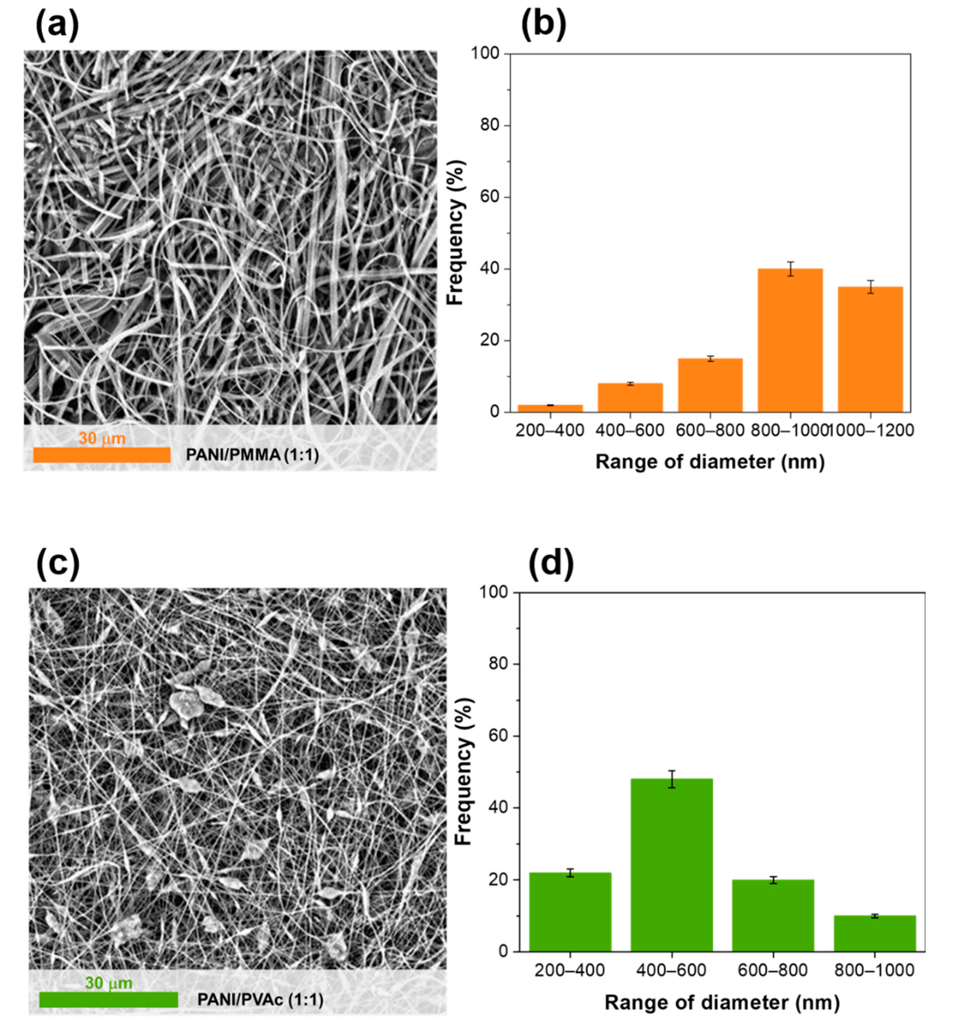
| PANI/PMMA (1:1) | PMMA | 960,000 | 1:1 | - | 1569 ± | Ribbons | 0.52 |
| PANI/PMMA (3:1) | PMMA | 960,000 | 3:1 | - | 1187 ± | Cornflakes | 0.23 |
| PANI/PVAcLMW (1:1) | PVAc | 100,000 | 1:1 | - | 987 ± | No fiber formation | - |
| PANI/PVAc (1:1) | PVAc | 500,000 | 1:1 | - | 1350 ± | Fiber beady | 36 |
| PANI/PVAc (2:1) | PVAc | 500,000 | 2:1 | - | 1600 ± | Fiber beady | 25 |
| PANI/PVAc (1:1)-GO | PVAc | 500,000 | 1:1 | GO 2% | 1450 ± | Fiber beady | 0.50 |
| PANI/PVAc (1:1)-FeOx | PVAc | 500,000 | 1:1 | Fe2O3 2% | 1460 ± | Fiber beady | 0.59 |
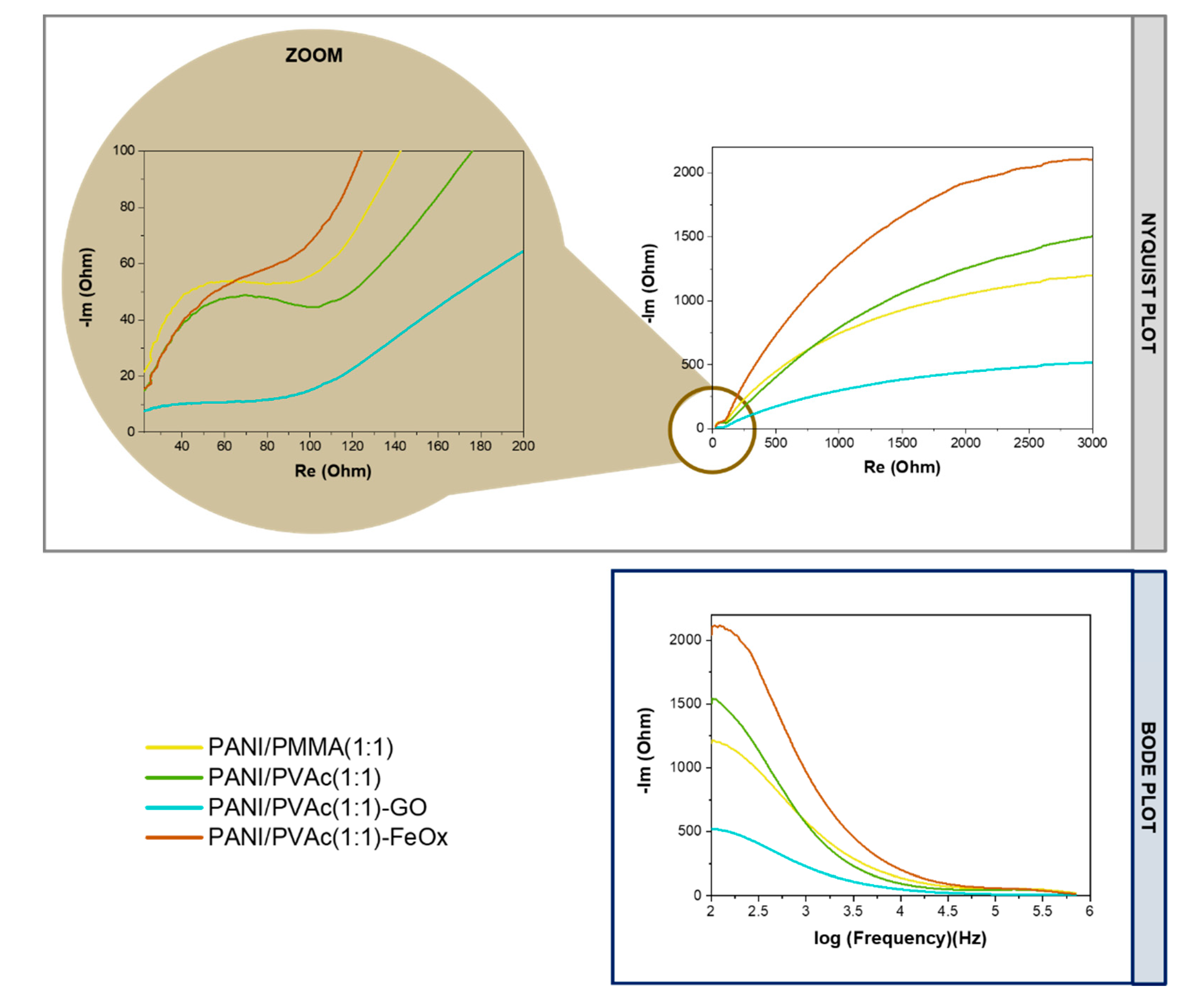
| Code | Re (Ohm) | Cc (nF) | Rc (Ohm) | Cdl (nF) | Rct (Ohm) | σ (Ohm⋅s−1/2) |
|---|---|---|---|---|---|---|
| PANI/PMMA (1:1) | 42.86 | 7.44 | 117.30 | 83.72 | 204.20 | 45,070.00 |
| PANI/PVAc (1:1) | 27.14 | 10.68 | 107.30 | 174.70 | 693.80 | 45,430.00 |
| PANI/PVAc (1:1)-GO | 27.26 | 10.74 | 108.00 | 180.00 | 827.70 | 42,069.00 |
| PANI/PVAc (1:1)-FeOx | 24.84 | 10.44 | 129.60 | 54.06 | 543.40 | 85,657.00 |
Publisher’s Note: MDPI stays neutral with regard to jurisdictional claims in published maps and institutional affiliations. |
© 2021 by the authors. Licensee MDPI, Basel, Switzerland. This article is an open access article distributed under the terms and conditions of the Creative Commons Attribution (CC BY) license (https://creativecommons.org/licenses/by/4.0/).
Share and Cite
Fotia, A.; Malara, A.; Paone, E.; Bonaccorsi, L.; Frontera, P.; Serrano, G.; Caneschi, A. Self Standing Mats of Blended Polyaniline Produced by Electrospinning. Nanomaterials 2021, 11, 1269. https://0-doi-org.brum.beds.ac.uk/10.3390/nano11051269
Fotia A, Malara A, Paone E, Bonaccorsi L, Frontera P, Serrano G, Caneschi A. Self Standing Mats of Blended Polyaniline Produced by Electrospinning. Nanomaterials. 2021; 11(5):1269. https://0-doi-org.brum.beds.ac.uk/10.3390/nano11051269
Chicago/Turabian StyleFotia, Antonio, Angela Malara, Emilia Paone, Lucio Bonaccorsi, Patrizia Frontera, Giulia Serrano, and Andrea Caneschi. 2021. "Self Standing Mats of Blended Polyaniline Produced by Electrospinning" Nanomaterials 11, no. 5: 1269. https://0-doi-org.brum.beds.ac.uk/10.3390/nano11051269