
Adsorption of K Ions on Single-Layer GeC for Potential Anode of K Ion Batteries


1
Key Laboratory of Automobile Materials of MOE and College of Materials Science and Engineering, Jilin University, Changchun 130012, China
2
Department of Physics and Astronomy, University of Missouri, Columbia, MO 65211, USA
3
Department of Chemistry, University of Missouri, Columbia, MO 65211, USA
4
State Key Laboratory of Automotive Simulation and Control, Jilin University, Changchun 130012, China
*
Author to whom correspondence should be addressed.
Nanomaterials 2021, 11(8), 1900; https://0-doi-org.brum.beds.ac.uk/10.3390/nano11081900
Submission received: 13 June 2021
/
Revised: 13 July 2021
/
Accepted: 19 July 2021
/
Published: 24 July 2021
(This article belongs to the Special Issue Novel Nanomaterials for Energy Conversion)
Abstract
:Potassium ion batteries (KIBs) are considered as promising alternatives to lithium ion batteries (LIBs), following the rapid increase of demand for portable devices, and the development of electric vehicles and smart grids. Though there has been a promising breakthrough in KIB tech niques, exploring the promising anode materials for KIBs is still a challenge. Rational design with first-principle methods can help to speed up the discovery of potential anodes for KIBs. With density functional calculations, GeC with graphene-like 2D structure (g-GeC) is shown to be a desired anode material for applications in KIBs. The results show that the 2D g-GeC with a high concentration of K ions is thermodynamically stable, due to the strong interaction between C and Ge in GeC layer with the proper interaction between K and GeC. The storage capacity can be about 320 mAh/g, higher than that (279 mAh/g) in graphite. The low energy barrier (0.13 eV) of K ions diffusion on the honeycomb structure with proper voltage profile indicates the fast charge transfer. These theoretical finds are expected to stimulate the future experimental works in KIBs.
1. Introduction
As the most commonly used commercial electrochemical batteries, lithium-ion batteries (LIBs) have been used as excellent energy storage systems to power various electronic products in smart electronics and have potential applications in the electric vehicle market since their commercialization [1,2,3]. However, with the miniaturization and lightening of equipment and people’s control of cost prices, LIBs’ techniques are being restricted by various factors, such as safety issues and scarcity of raw materials [4,5,6]. At present, the frequency of use of LIBs continues to increase, while the contradiction of raw materials faced by LIBs is increasingly exposed. Thus, people are gradually turning their attention to other metal-ion batteries [7,8,9]. Since potassium and lithium are of the same main group, the standard electrode potential of potassium-ion batteries (KIBs) is very close to that of LIBs. In addition, KIBs have higher ionic conductivity and less complex interfacial reaction than sodium-ion batteries as alternative potential techniques [10,11,12]. On the other hand, potassium is rich in reserves, which can reduce production costs for mass produce. In this way, KIBs have gradually aroused people’s enthusiasm for research in recent years [13].
KIB mainly consists of anode, cathode and electrolyte, in which the electrode materials determine the capacity and stability of the batteries. Due to the large ion radius of potassium ions and the improper interaction between traditional anode materials and K ions, the instability of anode materials is usually caused [10]. Therefore, looking for higher performance anode material has become one of the urgent tasks for the further development of KIBs.
For the past few years, two-dimensional materials with large surface areas that can achieve rapid ion diffusion have attracted great interest in the field of rechargeable ion batteries [9,14,15]. Graphene, the first and most fascinating 2D material, could be successfully synthesized by different methods, such as mechanical exfoliation of pristine graphite, oxidation-reduction method, chemical vapor precipitation and epitaxial growth method. It has been proven that graphene and graphene-based nanostructures can be used as an ideal negative electrode material for rechargeable ion batteries, such as LIBs [16,17,18,19]. Similarly, germanene and silicene as ion battery anode materials have been studied [20,21]. The conductivity of germanium without doping or alloying is not good, and germanium and carbon composite material has been proposed as a potential anode material with good conductivity due to sp2-carbon being in composite [22,23,24,25]. Recently, a graphene-like Ge/C composite called germagraphene (g-GeC) has been proposed, predicted by first-principles calculations to be a two-dimensional nonmagnetic semiconductor with a direct band gap of about 2.1 eV at K (K’) points [26,27,28,29,30]. The structure is the same as germanene, silicene and other honeycomb-like structures, but different from germanium is that it is a plane structure without buckling height [29]. Khossossi et al. found that GeC can be used as the anode material for lithium-sodium ion batteries [31], and proved that the redistribution of the charge in the germanium-benzene monolayer could give rise to the stronger adsorption of Li/Na ions on GeC than on the original graphene material.
In this paper, the first principles method was used to analyze the structure and electronic properties of g-GeC with the adsorption of potassium ions. The unique structure of g-GeC makes the germanium atom have an appropriate synergistic stabilization effect on the potassium ion, which makes the potassium ion more easily adsorbed on the germanium atom, different from Li and Na ions’ adsorption on g-GeC as observed by Khossossi et al. [31]. The adsorption structure is very stable due to the larger adsorption strength, compared to the binding energy of K in bulk K. By considering the different adsorption processes with different contents of K on g-GeC, we predicted the maximum capacity of GeC as the anode for KIBs with proper open-circuit voltage. By analyzing the ion diffusion properties, the potential barrier of the potassium ion diffusion on g-GeC is found to be low, especially at high content of K. The high migration rate of potassium ions with proper conductivity on g-GeC meets the requirement of the mobility of an anode. By analyzing the electronic properties, such as band structure, density of states and charge distribution, it is systematically proved that GeC has the potential to be used as anode material for KIBs.
2. Materials and Methods
The structure of GeC involved in this paper shows hexagonal symmetry similar to graphene, where the germanium and the carbon atoms are arranged in alternating sp2-hybridization to form a network. Its stable two-dimensional (2D) geometry is planar, similar to graphene, with vertical electron orbitals for π bonds. The dynamic stability of the structure of GeC has been demonstrated [29,31,32].
All our first-principles calculations were performed on the basis of density functional theory as implemented in Vienna Ab initio Simulation Package (VASP) [33,34]. The generalized gradient approximation (GGA) as formulated and parameterized by the Perdew –Burke–Ernzerhof (PBE) functional was used for the electron–electron exchange correlation [35]. Electron−ion interactions were described by the method of projector augmented wave (PAW) [36,37]. An energy cutoff of 550 eV was selected for the plane wave expansion of valence electron wave functions. The effect of van der Waals (vdW) interaction was taken into account by using the DFT-D3 approach [38]. The Brillouin zones were sampled using a reciprocal spacing of 0.02 Å−1, and the Gamma-centered method was followed. The vacuum of 20 Å was applied along the direction perpendicular to avoid the virtual interactions along z direction due to the influence of periodic boundary conditions.
3. Results and Discussion
3.1. Adsorption of K Ions on GeC in Different Supercell
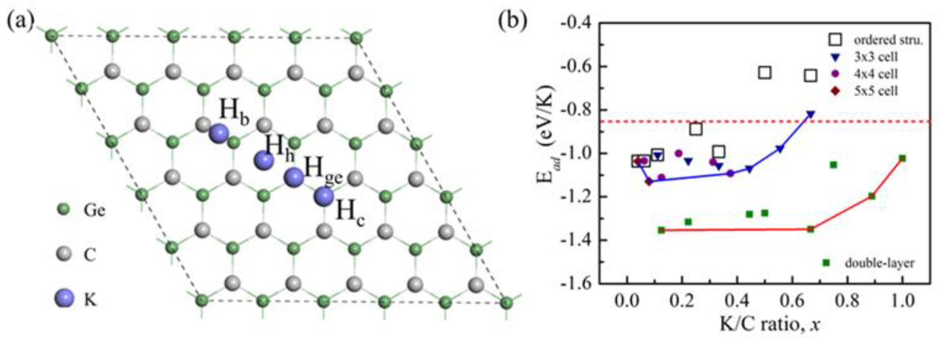
We began with the search for proper absorption sites at a low concentration of K (K/C ratio x = 0.04). The calculations were performed in a 5 × 5 × 1 supercell of g-GeC, as depicted in Figure 1a. Four possible adsorption sites with high symmetry were under our consideration, including Hge, Hc, Hh and Hb, corresponding K ions’ adsorption on the Ge atom, C atom, central position of hexagonal ring and bridge site between Ge and C atoms, respectively. The stable existence of potassium ions in the structure can be determined by the binding between adatom and structure. To evaluate the binding strength, the adsorption energy can be analyzed by the following formula [19]:
where EK-GeC, EGeC and EK are total energies of GeC with K adsorption, isolated GeC and isolated K atom, respectively, and n is the number of adsorbed K atoms on GeC in the adsorption state. According to this definition, negative adsorption energy represents a stable configuration with favorable interaction, and positive adsorption energy represents an unstable structure. The adsorption energies of different adsorption sites can be obtained in Table 1. It is clear that there is proper interaction between K and GeC. Hge is the most stable absorption site, followed by Hh and Hc. In the optimization process, if the atomic position in the GeC plane isn’t fixed, the potassium atom at the bridge position is accustomed to migrating over the Ge atom. Here, it is confirmed that the bridge site is unstable.
With the K ions’ adsorption at Hge sites, we analyzed the change of adsorption energy following the increase of K content. By considering the ordered adsorption state of K ions, we analyzed the change of K concentration from x = 0.04 to 0.667 with the construction of different models, including the adsorption of one K ion in 5 × 5, 4 × 4, 3 × 3, 2 × 2, √3 × √3 and √2 × √2 supercells and two K ions in a √3 × √3 supercell. The typical adsorption configurations of a K ion in high content are shown in Figure S1 of Supplementary Materials. The corresponding adsorption energies are shown with the hollow squares in Figure 1b. It is clear that there is a decreasing trend of adsorption strength with the increase of K content. The binding energy of K atom in bulk K is about 0.87 eV. This means that if we use the bulk K as the reference state, as the red dot line shows in Figure 1b, it is possible that the adsorption becomes improper in the electrochemical environment if the concentration is more than 0.5.
We have noticed that the interaction between K ions on g-GeC is repulsive, while the interaction between K and the Ge atom under the K ion induces a local strain. It is possible that the energies of other configurations are lower than that of the structure with the ordered adsorption state of K at the same concentration. We constructed the other possible configurations of K adsorption with different contents of K in which the distance between K ions on g-GeC is as large as possible in the restriction of periodic boundary condition. These configurations are constructed in supercells 3 × 3, 4 × 4, and 5 × 5, as shown in Figures S2–S4 of Supplementary Materials. The results are shown in Figure 1b. Indeed, it is observed that there are other low energy configurations. With the consideration of these configurations, the maximal concentration of K adsorption is about 0.67.
As the concentration increases, K ions deviate from the adsorption sites of Ge due to the Coulomb repulsion between K ions, as shown in Figures S2 and S3. It is possible to reduce the repulsive interaction between K ions to a large extent if K ions are adsorbed by means of two-surface adsorption on g-GeC layer (double-layer model). We constructed the configurations with different contents of K by proposing the K adsorption in different supercells of √3 × √3, 2 × 2, 3 × 3 and 4 × 4 in Figures S5–S8 of Supplementary Materials. In these configurations, the K ions are adsorbed on both surfaces in the stagger way to reduce the local strain. It is known that if the adsorption strength (|Ead|) per K ion on g-GeC is larger than the binding energy of a K atom in bulk K, there will be no potassium clusters formed in the process of K loading [19]. In Figure 1b, it is clear that the adsorption with two surfaces is more stable than that just on one surface. The maximal concentration of K adsorption can reach x = 1. In Figure S9, the change of lattice parameter as a function of K concentration is plotted for both adsorption processes. The change in the lattice constant is less noticeable as the concentration of K increases. Thus, the strain in the entire lattice plane due to K adsorption is weak.
In order to check the stability of this material system with K adsorption, we calculated the formation energy due to the K adsorption with the formula:
where EK-GeC, EGeC and EK-bulk are total energies of GeC with K adsorption, isolated GeC and bulk K, respectively. The results for single-layer K adsorption and double-layer adsorption (two sides of g-GeC) are shown in Figure S10. It is clear that this material with K adsorption is energetically stable. It is also noticed that in other materials, such as single layer Mxene, it is possible that double-layer K ions are adsorbed by way of one side adsorption [39]. In the single-layer g-GeC, the adsorption of K on g-GeC is not so strong that there is a double-layer of K ions adsorption on one side.
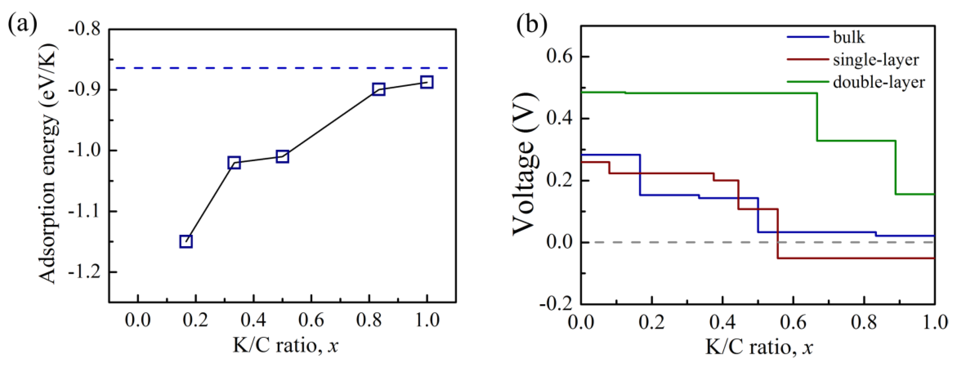
We also analyzed the intercalation of K ions in bulk g-GeC in order to estimate the adsorption in multi-layer g-GeC. The adsorption models for different concentrations of K are depicted in Figures S11 and S12. As shown in Figure 2a, it was found that the maximal concentration was also x = 1. The theoretical capacity is approximately evaluated with the maximal concentration of K ions in the K loading process. It can be calculated by the formula C = xF/MGeC, where F, x, and MGeC are Faraday constant (26.8 Ah mol−1), K concentration inserted in g-GeC per formula cell, and mole mass of one g-GeC formula cell with the inserted K, respectively. It is clear that when potassium performs two-surface adsorption on g-GeC monolayer or intercalates into bulk g-GeC, the capacity at the insertion concentration of x = 1 is 316.7 mA h g−1.
As mentioned above, we checked the adsorption of K ions on mono-layer g-GeC and in bulk g-GeC. In the reasonable range of adsorption concentrations, the K ions can be stably adsorbed on g-GeC. For the anode applications, we can evaluate the open-circuit voltage (OCV) with the K loading by the voltage profile. It is related to the Gibbs free energies in both charged and discharged states by V = −ΔG/ΔxF, where ΔG and Δx are the change of Gibbs free energies and K concentration in both states, respectively. In the intercalation of ions, such as Li, Na and K in anode, the contributions of vibrational and configurational entropy are small and can be ignored. Thus, the difference in Gibbs energies can be approximated to the change of energy by ΔG ≈ E(KxGeC) − E(GeC) − xE(K). In Figure 2b, open circuit voltage curves are plotted for the single-layer adsorption on one side of g-GeC monolayer, double-layer adsorption on two sides of g-GeC monolayer and intercalation of K in bulk g-GeC. From the K concentration of x = 1 with two-surface adsorption in K-loading state, the OCV is about 0.15 V. In the single-layer adsorption model, the OCV becomes negative when the K concentration is more than 0.55. For the intercaltion of K in bulk g-GeC, there is a good voltage profile, with the largest OCV less than 0.3 V. Generally speaking, materials with an averaged OCV lower than 1 V can be used as the anode in KIBs. Thus, the applicable OCV (the largest OCV less than 0.5 V) provides feasibility for the GeC to be applied as anodes for KIBs.
3.2. Analysis of Electronic Properties
To gain a more detailed insight into the mechanism of the diverse adsorption behavior of K ions on the GeC, charge density difference is applied for describing the charge distribution, and the charge density difference in real space can be estimated by the following equation [40]:
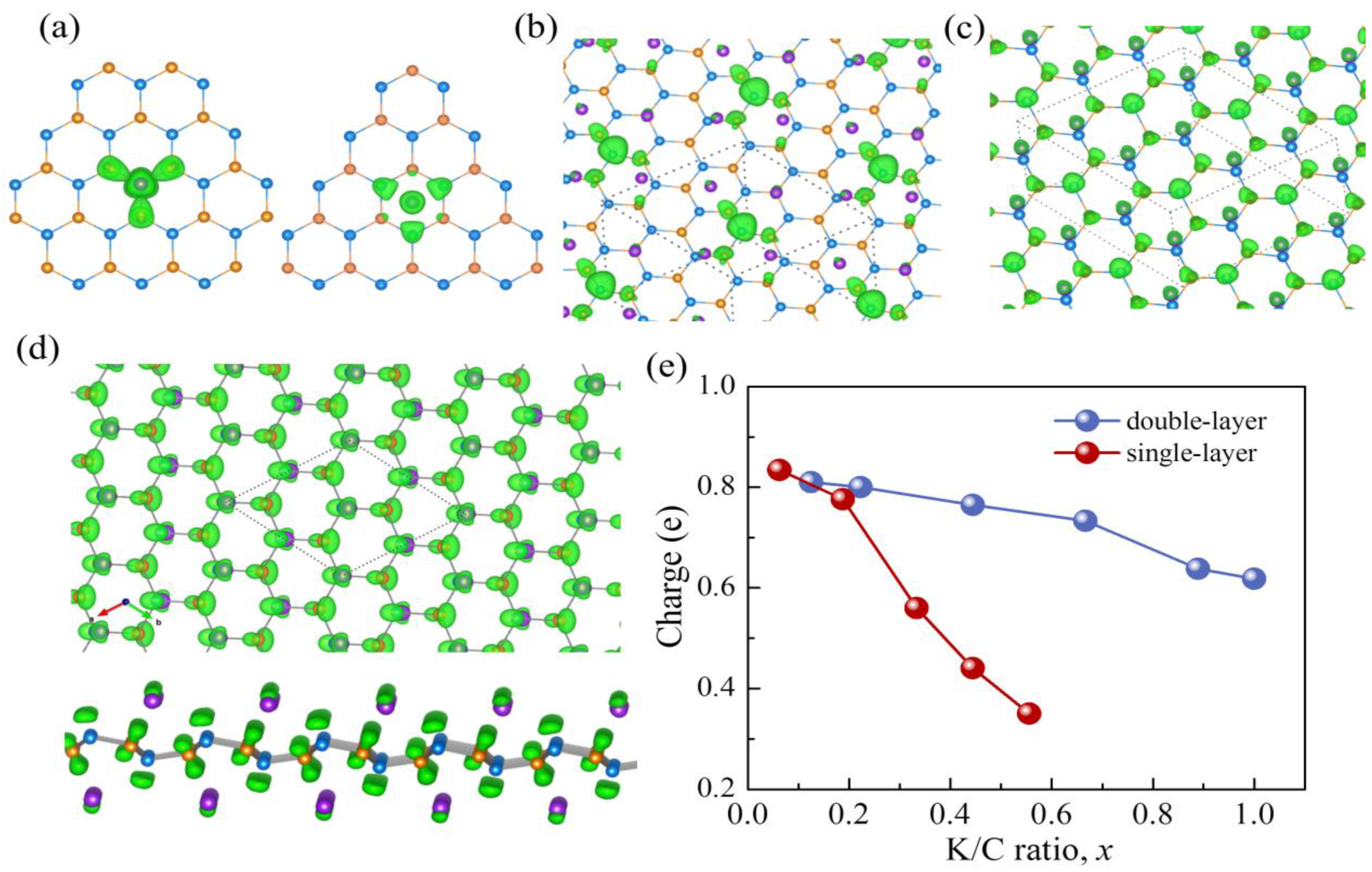
where CHGK-GeC(r), CHGGeC(r) and CHGK(r) are the electronic charge distributions of the K-adsorbed g-GeC, free g-GeC and isolated potassium atom, respectively. In Figure 3a, potassium atoms are adsorbed at HGe and Hh sites on the left and right sides, respectively. The charge redistributions in the K adsorption configurations are rather symmetrical.
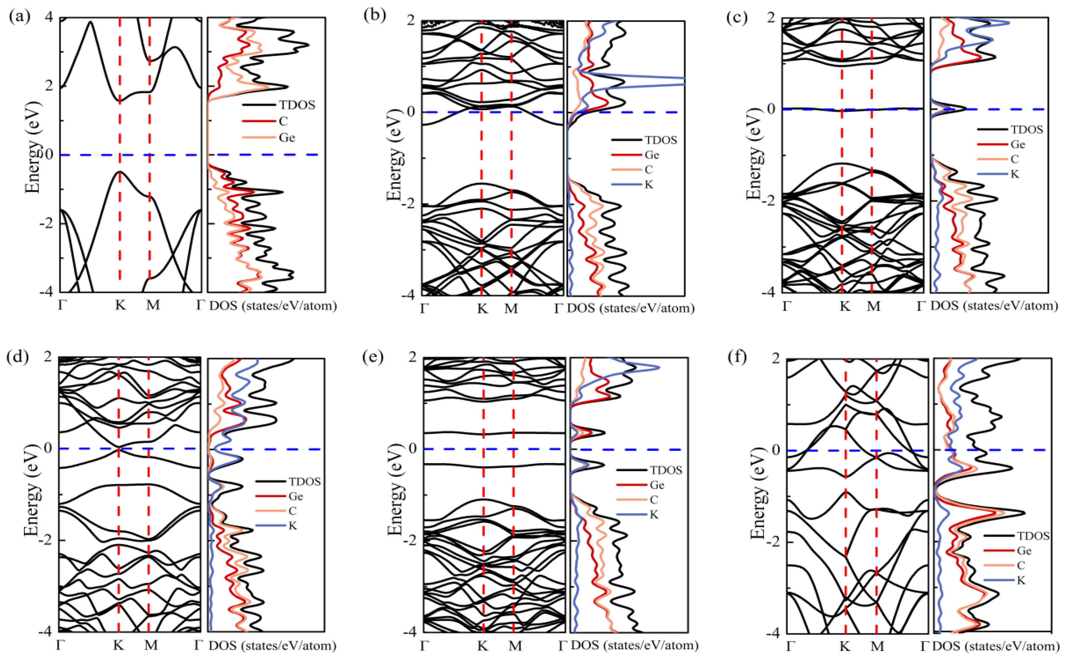
The K ion at Hh site has a uniform charge transfer mainly with the surrounding three carbon atoms. In Figure 4a, we calculated the band structure and partial density of states (PDOS) of pristine g-GeC. It is clear that g-GeC is a semiconductor, as the previous reports. The states near the valance band’s top are mainly from the contribution of carbon atoms, while the states near the conduction band’s bottom are mainly due to the Ge p-orbitals. Therefore, the change of K is transferred to the nearby C atoms and thus, results in the up-shift of Fermi level into conduction bands in Figure 4b, since the energy level of K s-orbital is higher than the conduction band’s bottom. For the adsorption of the K ion on HGe site, the charge of K is transferred to not only the nearby C atoms, but also the nether Ge atom. The interaction between K and the nearby three C atoms results in a down-shift of the nether Ge atom from g-GeC plane. The stable state among the K ion, nearby three C atoms, and nether Ge is formed by the electrostatic interaction with charge transfer. Thus, a localized band appears in the band gap of g-GeC in Figure 4c. It results from the contribution of K and nearby C and Ge atoms. Therefore, the adsorption of the K ion on Hge site is more stable than on Hh site in Table 1. This is different from the adsorption of Li and Na with Hh site on g-GeC [31].
From the perspective of high-concentration adsorption, we plotted the charge density difference at the concentrations of x = 0.44 and 0.67 in Figure 3b,c, respectively. It is clear that the repulsion among K ions results in the deviation of K adsorption on Hge in Figure 3b. The charge transferred from K is localized on a Ge atom with the nearby three C atoms which is in the center of four K ions. The deviation of K on Hge can be ascribed to the electrostatic trap of the aggregated charge on Ge at the center of four K ions. With the increase of K concentration up to x = 0.67 in Figure 3c, the arrangement of K ions comes to be ordered on Hge sites with the pattern of hexagonal symmetry. The charge transferred from K is accumulated on a Ge atom with the nearby three C atoms, which are in the center of a six-ring formed by six K ions in Figure 3c. With the increase of K concentration, the localized band in the band gap disappears. As shown in Figure 4d and Figure S13, the band structures of x = 0.44 and 0.67 indicate that the charge transfer results in the up-shift of Fermi level. The weak strain of g-GeC induced by the adsorption of K ions results in the closing of the band gap. The system becomes conductive.
Subsequently, we checked the change of electronic structure due to the K adsorption through the process of two-surface adsorption. For example, at x = 0.125 with two K atoms adsorbed on g-GeC with both surfaces in a supercell of 4 × 4. In Figure 4e, two K atoms induce two localized bands in the band gap of g-GeC, similar to the adsorption on one surface with the low concentration of K in Figure 4c. Following the increase of K content, the Fermi level is shifted up and the system becomes conductive, as shown in Figure 4f. The charge transfer at x = 1 is shown in Figure 3d. The K ions form the structure of up-down chains and the induced weak strain from the K adsorption results in the zigzag structure of the g-GeC plane along a direction perpendicular to the K chain direction, as shown by the side view in Figure 3d. The transferred charge is evenly distributed on both sides of the g-GeC plane.
To qualitatively estimate the charge transfer process, we illustrate the change of transferring charge with the increase of K concentration by the analysis of Bader charge on K in Figure 3e. The amount of charge transferred by each K ion in the two-surface adsorption is greater than that in the one-surface adsorption for each concentration of K. This proves that the interaction between g-GeC and K ions by way of two-surface adsorption is stronger than that with the one-surface adsorption, observed in Figure 1b. With the increase of concentration, the amount of charge transfer in the monolayer visibly decreases. This conforms to the trend of adsorption energy and proves that the adsorption strength of the K ion on g-GeC gradually becomes weak following the increase of K concentration.
3.3. Diffusion Mechanism of Potassium Ion
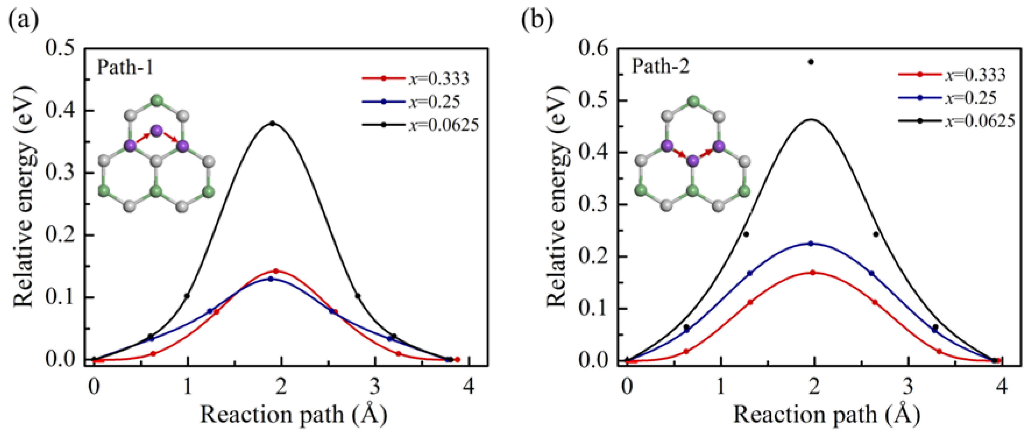
The charge and discharge rate capability are mainly determined by the ion migration performance. The nudged elastic band (NEB) method has been used to investigate the diffusion properties at different concentrations. In the course of our calculations, the potassium ion has preferred to stay above the Ge atom, so we chose the positions above the adjacent two Ge atoms as the initial and final state positions. There are two typical paths shown in the insets of Figure 5a,b, respectively. The path-1 is Ge-Hh-Ge, where Hh is the hexagonal site. The path-2 is Ge-C-Ge. Both paths can complete the diffusion in the entire material range and belong to the complete diffusion path. The K ion along both path-1 and path-2 diffuses through Hh and Hc sites, respectively. It can be seen in Figure 5, compared with path-2, the diffusion energy barrier of path-1 is lower. Thus, the K ions are inclined to diffusion along path-1 through Hh site. In this way, there are three symmetric three pathways at each Hge site. Following the K loading, the diffusion barrier decreases for both paths. At the higher concentration, the diffusion barrier becomes similar to path-1 and path-2. At x = 0.33, the energy barrier of diffusion is about 0.13 eV. This low diffusion barrier indicates the fast charge/discharge rate for K on g-GeC.
4. Conclusions
As mentioned above, we have systematically studied the impact of g-GeC as an anode on the performance of KIBs based on the density functional theory. In the processes, we found that HGe site on g-GeC is the most favorable adsorption site for a single K ion, and the adsorption energy is appropriate, with a value of −1.04 eV. Because of the enhancement of the repulsion between potassium and potassium, the adsorption strength of each K ion decreases gradually along with the increase of the K/C ratio. The theoretical capacity is estimated to be up to about 320 mA h g−1. In addition, g-GeC exhibits metallic properties during the whole potassium insertion process. This indicates that the electrical conductivity of the g-GeC structure is gradually improving with the K loading, since the pristine g-GeC is a semiconductor. In the end, the diffusion potential along the path Ge-Hh-Ge is about 0.13 eV at the concentration of x = 0.33, which meets the requirement of high charging and discharging efficiency of KIBs. In view of the merits above, g-GeC has the potential to be an alternative anode material for KIBs.
Supplementary Materials
The following are available online at https://0-www-mdpi-com.brum.beds.ac.uk/article/10.3390/nano11081900/s1. Figures S1–S4: The structure models for K-adsorbed g-GeC in the way of one-surface adsorption with different concentrations of K, Figures S5–S8: The structure models for K-adsorbed g-GeC in the way of two-surface adsorption with different concentrations of K, Figure S9: Lattice changes with the K concentration, Figure S10: formation energies, Figures S11 and S12: The structure models for K-adsorbed bulk g-GeC, Figure S13: Electronic properties of g-GeC with x = 0.67.
Author Contributions
Conceptualization, X.F. and W.Z.; methodology, X.F., D.J.S.; software, Y.M.; validation, Y.M., S.X., X.F. and D.J.S.; formal analysis, X.F., Y.M., S.X.; investigation, X.F., Y.M.; resources, X.F., Y.M.; data curation, X.F., Y.M.; writing—original draft preparation, Y.M.; writing—review and editing, X.F., D.J.S., W.Z.; visualization, Y.M., X.F.; supervision, X.F.; project administration, X.F.; funding acquisition, X.F., W.Z. All authors have read and agreed to the published version of the manuscript.
Funding
This research was supported by the National Key R&D Program of China (Grant No. 2016YFA0200400) and the National Natural Science Foundation of China (Grant No.51627805).
Data Availability Statement
All necessary data have been illustrated in the manuscript and the Supplementary Materials. Additional data may be obtained from corresponding authors with their permission.
Conflicts of Interest
The authors declare no conflict of interest.
References
- Li, M.; Lu, J.; Chen, Z.; Amine, K. 30 Years of Lithium-Ion Batteries. Adv. Mater. 2018, 30, 1800561. [Google Scholar] [CrossRef] [PubMed] [Green Version]
- Choi, J.W.; Aurbach, D. Promise and reality of post-lithium-ion batteries with high energy densities. Nat. Rev. Matter. 2016, 1, 1–6. [Google Scholar] [CrossRef]
- Nitta, N.; Wu, F.; Lee, J.T.; Yushin, G. Li-ion battery materials: Present and future. Mater. Today 2015, 18, 252–264. [Google Scholar] [CrossRef]
- Goodenough, J.B.; Kim, Y. Challenges for Rechargeable Li Batteries. Chem. Mater. 2009, 22, 587–603. [Google Scholar] [CrossRef]
- Etacheri, V.; Marom, R.; Elazari, R.; Salitra, G.; Aurbach, D. Challenges in the development of advanced Li-ion batteries: A review. Energy Environ. Sci. 2011, 4, 3243–3262. [Google Scholar] [CrossRef]
- Eftekhari, A. Lithium Batteries for Electric Vehicles: From Economy to Research Strategy. ACS Sustain. Chem. Eng. 2019, 7, 5602–5613. [Google Scholar] [CrossRef]
- Kubota, K.; Dahbi, M.; Hosaka, T.; Kumakura, S.; Komaba, S. Towards K-Ion and Na-Ion Batteries as “Beyond Li-Ion”. Chem. Rec. 2018, 18, 459–479. [Google Scholar] [CrossRef] [PubMed]
- Wang, H.-G.; Li, W.; Liu, D.-P.; Feng, X.-L.; Wang, J.; Yang, X.-Y.; Zhang, X.-b.; Zhu, Y.; Zhang, Y. Flexible Electrodes for Sodium-Ion Batteries: Recent Progress and Perspectives. Adv. Mater. 2017, 29, 1703012. [Google Scholar] [CrossRef]
- Yang, E.; Ji, H.; Jung, Y. Two-Dimensional Transition Metal Dichalcogenide Monolayers as Promising Sodium Ion Battery Anodes. J. Phys. Chem. C 2015, 119, 26374–26380. [Google Scholar] [CrossRef]
- Hwang, J.-Y.; Myung, S.-T.; Sun, Y.-K. Recent Progress in Rechargeable Potassium Batteries. Adv. Funct. Mater. 2018, 28, 1802938. [Google Scholar] [CrossRef]
- Wu, X.; Leonard, D.P.; Ji, X. Emerging Non-Aqueous Potassium-Ion Batteries: Challenges and Opportunities. Chem. Mater. 2017, 29, 5031–5042. [Google Scholar] [CrossRef]
- Komaba, S.; Hasegawa, T.; Dahbi, M.; Kubota, K. Potassium intercalation into graphite to realize high-voltage/high-power potassium-ion batteries and potassium-ion capacitors. Electrochem. Commun. 2015, 60, 172–175. [Google Scholar] [CrossRef] [Green Version]
- Dhir, S.; Wheeler, S.; Capone, I.; Pasta, M. Outlook on K-Ion Batteries. Chem 2020, 6, 2442–2460. [Google Scholar] [CrossRef]
- Huang, H.; Li, K.; Fan, X.; Singh, D.J.; Zheng, W.T. Storage of Na in layered graphdiyne as high capacity anode materials for sodium ion batteries. J. Mater. Chem. A 2019, 7, 25609–25618. [Google Scholar] [CrossRef]
- Er, D.; Li, J.; Naguib, M.; Gogotsi, Y.; Shenoy, V.B. Ti3C2 MXene as a high capacity electrode material for metal (Li, Na, K, Ca) ion batteries. ACS Appl. Mater. Interfaces 2014, 6, 11173–11179. [Google Scholar] [CrossRef]
- Sun, Y.; Wu, Q.; Shi, G. Graphene based new energy materials. Energy Environ. Sci. 2011, 4, 1113–1132. [Google Scholar] [CrossRef]
- Huang, X.; Zeng, Z.; Fan, Z.; Liu, J.; Zhang, H. Graphene-based electrodes. Adv. Mater. 2012, 24, 5979–6004. [Google Scholar] [CrossRef]
- Yoo, E.; Kim, J.; Hosono, E.; Zhou, H.-S.; Kudo, T.; Honma, I. Large Reversible Li Storage of Graphene Nanosheet Families for Use in Rechargeable Lithium Ion Batteries. Nano Lett. 2008, 8, 2277–2282. [Google Scholar] [CrossRef]
- Fan, X.; Zheng, W.T.; Kuo, J.L.; Singh, D.J. Adsorption of single Li and the formation of small Li clusters on graphene for the anode of lithium-ion batteries. ACS Appl. Mater. Interfaces 2013, 5, 7793–7797. [Google Scholar] [CrossRef] [PubMed]
- Xu, S.; Fan, X.; Liu, J.; Singh, D.J.; Jiang, Q.; Zheng, W. Adsorption of Li on single-layer silicene for anodes of Li-ion batteries. Phys. Chem. Chem. Phys. 2018, 20, 8887–8896. [Google Scholar] [CrossRef] [PubMed]
- Bhuvaneswari, R.; Nagarajan, V.; Chandiramouli, R. Germanene nanosheets as a novel anode material for sodium-ion batteries—A first-principles investigation. Mater. Res. Express 2018, 6, 035504. [Google Scholar] [CrossRef]
- Fang, S.; Shen, L.; Zheng, H.; Zhang, X. Ge–graphene–carbon nanotube composite anode for high performance lithium-ion batteries. J. Mater. Chem. A 2015, 3, 1498–1503. [Google Scholar] [CrossRef]
- Han, L.; Tang, J.; Yang, R.; Wei, Q.; Wei, M. Stable Li-ion storage in Ge/N-doped carbon microsphere anodes. Nanoscale 2021, 13, 5307–5315. [Google Scholar] [CrossRef]
- Choe, H.-S.; Kim, S.-J.; Kim, M.-C.; Kim, D.-M.; Lee, G.-H.; Han, S.-B.; Kwak, D.-H.; Park, K.-W. Synthesis of Ge/C composites as anodes using glucose as a reductant and carbon source for lithium-ion batteries. RSC Adv. 2016, 6, 72926–72932. [Google Scholar] [CrossRef]
- Wang, Y.; Luo, S.; Chen, M.; Wu, L. Uniformly Confined Germanium Quantum Dots in 3D Ordered Porous Carbon Framework for High-Performance Li-ion Battery. Adv. Funct. Mater. 2020, 30, 2000373. [Google Scholar] [CrossRef]
- Ersan, F.; Gökçe, A.G.; Aktürk, E. Point defects in hexagonal germanium carbide monolayer: A first-principles calculation. Appl. Surf. Sci. 2016, 389, 1–6. [Google Scholar] [CrossRef]
- Guilhon, I.; Teles, L.K.; Marques, M.; Pela, R.R.; Bechstedt, F. Influence of structure and thermodynamic stability on electronic properties of two-dimensional SiC, SiGe, and GeC alloys. Phys. Rev. B 2015, 92, 075435. [Google Scholar] [CrossRef]
- Ji, Y.; Dong, H.; Hou, T.; Li, Y. Monolayer graphitic germanium carbide (g-GeC): The promising cathode catalyst for fuel cell and lithium–oxygen battery applications. J. Mater. Chem. A 2018, 6, 2212–2218. [Google Scholar] [CrossRef]
- Şahin, H.; Cahangirov, S.; Topsakal, M.; Bekaroglu, E.; Akturk, E.; Senger, R.T.; Ciraci, S. Monolayer honeycomb structures of group-IV elements and III-V binary compounds: First-principles calculations. Phys. Rev. B 2009, 80, 155453. [Google Scholar] [CrossRef] [Green Version]
- Lü, T.-Y.; Liao, X.-X.; Wang, H.-Q.; Zheng, J.-C. Tuning the indirect–direct band gap transition of SiC, GeC and SnC monolayer in a graphene-like honeycomb structure by strain engineering: A quasiparticle GW study. J. Mater. Chem. 2012, 22, 10062–10068. [Google Scholar] [CrossRef]
- Khossossi, N.; Banerjee, A.; Essaoudi, I.; Ainane, A.; Jena, P.; Ahuja, R. Thermodynamics and kinetics of 2D g-GeC monolayer as an anode materials for Li/Na-ion batteries. J. Power Sources 2021, 485, 229318. [Google Scholar] [CrossRef]
- Gökçe, A.G.; Ersan, F. Adsorption of alkali and alkaline earth metal atoms and dimers on monolayer germanium carbide. Philos. Mag. 2017, 97, 155–167. [Google Scholar] [CrossRef]
- Kresse, G. Ab initio molecular dynamics for liquid metals. J. Non-Cryst. Solids 1995, 192, 222–229. [Google Scholar] [CrossRef]
- Kresse, G.; Furthmüller, J. Efficiency of ab-initio total energy calculations for metals and semiconductors using a plane-wave basis set. Comput. Mater. Sci. 1996, 6, 15–50. [Google Scholar] [CrossRef]
- Perdew, J.P.; Burke, K.; Ernzerhof, M. Generalized Gradient Approximation Made Simple. Phys. Rev. Lett. 1997, 78, 1396. [Google Scholar] [CrossRef] [Green Version]
- Kresse, G.; Joubert, D. From ultrasoft pseudopotentials to the projector augmented-wave method. Phys. Rev. B 1999, 59, 1758–1775. [Google Scholar] [CrossRef]
- Blochl, P.E. Projector augmented-wave method. Phys. Rev. B 1994, 50, 17953–17979. [Google Scholar] [CrossRef] [PubMed] [Green Version]
- Grimme, S.; Ehrlich, S.; Goerigk, L. Effect of the Damping Function in Dispersion Corrected Density Functional Theory. J. Comput. Chem. 2011, 32, 1456–1465. [Google Scholar] [CrossRef]
- Li, N.; Li, Y.; Fan, J. Prediction of chemically ordered dual transition metal carbides (MXenes) as high-capacity anode materials for Na-ion batteries. Nanoscale 2021, 13, 7234–7243. [Google Scholar] [CrossRef]
- Fan, X.; Liu, L.; Lin, J.; Shen, Z.; Kuo, J.-L. Density Functional Theory Study of Finite Carbon Chains. ACS Nano. 2009, 3, 3788–3794. [Google Scholar] [CrossRef]
Figure 1.
(a) Four possible K ion adsorption sites in a 5 × 5 × 1 supercell of g-GeC surface, (b) the adsorption energies of K ions on g-GeC as functions of the ratio of K/C in various supercells for both one-surface and two-surface adsorption. Note the green square in (b) indicates the two-surface adsorption of K ions on g-GeC (double-layer model).

Figure 2.
(a) The adsorption energy as a function of K concentration for bulk g-GeC and (b) the voltage profile of open-circuit voltage for K interaction in bulk g-GeC, one side adsorption (single-layer model) and two-surface adsorption (double-layer model) on monolayer g-GeC.
Figure 2.
(a) The adsorption energy as a function of K concentration for bulk g-GeC and (b) the voltage profile of open-circuit voltage for K interaction in bulk g-GeC, one side adsorption (single-layer model) and two-surface adsorption (double-layer model) on monolayer g-GeC.

Figure 3.
Distribution of electron charge density difference at the K/C ratio of (a) x = 0.0625 with K adsorption on Hge and Hh sites in 4 × 4 × 1 supercell, (b) x = 0.44 and (c) x = 0.67 in 3 × 3 × 1 supercell, and (d) x = 1 with K adsorption by way of two-surface adsorption in 2 × 2 × 1 supercell, (e) the change of averaged charge amount that K loses with increase of K concentration. The orange, blue, and purple spheres represent C, Ge and K atoms, respectively. The green is for the transferred charge from K to g-GeC.

Figure 4.
Band structure, density of states (DOS) and partial density of states (PDOS) of (a) pristine g-GeC, (b,c) g-GeC with K adsorption on Hh and Hge sites at low concentration of x = 0.0626, (d) g-GeC with K concentration of x = 0.44, and (e,f) g-GeC with K adsorption by way of two-surface adsorption with K concentrations of x = 0.125 and x = 1.

Figure 5.
The diffusion barrier profiles of one K ion migration on g-GeC along (a) path-1 (Ge-Hh-Ge) and (b) path-2 (Ge-C-Ge) at different concentrations.
Figure 5.
The diffusion barrier profiles of one K ion migration on g-GeC along (a) path-1 (Ge-Hh-Ge) and (b) path-2 (Ge-C-Ge) at different concentrations.


Table 1.
The parameters of K adsorption on g-GeC layer calculated in supercell 5 × 5 × 1, including the distance between K and g-GeC layer and corresponding adsorption energy at different absorption sites.
Table 1.
The parameters of K adsorption on g-GeC layer calculated in supercell 5 × 5 × 1, including the distance between K and g-GeC layer and corresponding adsorption energy at different absorption sites.
| Site | Hge | Hc | Hh | Hb |
|---|---|---|---|---|
| Distance (Å) | 2.50 | 2.88 | 2.53 | |
| Ead (eV) | −1.04 | −0.44 | −0.57 | unstable |
Publisher’s Note: MDPI stays neutral with regard to jurisdictional claims in published maps and institutional affiliations. |
© 2021 by the authors. Licensee MDPI, Basel, Switzerland. This article is an open access article distributed under the terms and conditions of the Creative Commons Attribution (CC BY) license (https://creativecommons.org/licenses/by/4.0/).
Share and Cite
MDPI and ACS Style
Ma, Y.; Xu, S.; Fan, X.; Singh, D.J.; Zheng, W. Adsorption of K Ions on Single-Layer GeC for Potential Anode of K Ion Batteries. Nanomaterials 2021, 11, 1900. https://0-doi-org.brum.beds.ac.uk/10.3390/nano11081900
AMA Style
Ma Y, Xu S, Fan X, Singh DJ, Zheng W. Adsorption of K Ions on Single-Layer GeC for Potential Anode of K Ion Batteries. Nanomaterials. 2021; 11(8):1900. https://0-doi-org.brum.beds.ac.uk/10.3390/nano11081900
Chicago/Turabian StyleMa, Yue, Sen Xu, Xiaofeng Fan, David J. Singh, and Weitao Zheng. 2021. "Adsorption of K Ions on Single-Layer GeC for Potential Anode of K Ion Batteries" Nanomaterials 11, no. 8: 1900. https://0-doi-org.brum.beds.ac.uk/10.3390/nano11081900
Note that from the first issue of 2016, this journal uses article numbers instead of page numbers. See further details here.