
Effect of SnO2 Colloidal Dispersion Solution Concentration on the Quality of Perovskite Layer of Solar Cells

 and
and 
Abstract
:1. Introduction
2. Experiments
2.1. Materials
2.2. Device Fabrication
2.2.1. ITO Substrate Cleaning Process
2.2.2. Electron Transport Layer (ETL) Preparing Process
2.2.3. Perovskite Absorption Layer Preparing Process
2.2.4. Hole Transport Layer (HTL) Preparing Process
2.2.5. Counter Electrode Preparation Process
2.3. Characterization
3. Results and Discussion
4. Conclusions
Supplementary Materials
Author Contributions
Funding
Institutional Review Board Statement
Informed Consent Statement
Data Availability Statement
Conflicts of Interest
References
- Elseman, A.M.; Xu, C.; Yao, Y.; Elisabeth, M.; Niu, L.; Malavasi, L.; Song, Q.L. Electron transport materials: Evolution and case study for high-efficiency perovskite solar cells. Sol. RRL 2020, 4, 2000136. [Google Scholar] [CrossRef]
- Huang, H.; Liu, X.; Duan, M.; Ji, J.; Jiang, H.; Liu, B.; Sajid, S.; Cui, P.; Wei, D.; Li, Y.; et al. Dual function of surface alkali-gas erosion on SnO2 for efficient and stable perovskite solar cells. ACS Appl. Energy Mater. 2020, 3, 5039–5049. [Google Scholar] [CrossRef]
- Shahiduzzaman; Fukaya, S.; Muslih, E.Y.; Wang, L.; Nakano, M.; Akhtaruzzaman; Karakawa, M.; Takahashi, K.; Nunzi, J.-M.; Taima, T. Metal oxide compact electron transport layer modification for efficient and stable perovskite solar cells. Materials 2020, 13, 2207. [Google Scholar] [CrossRef] [PubMed]
- Ali, J.; Li, Y.; Gao, P.; Hao, T.; Song, J.; Zhang, Q.; Zhu, L.; Wang, J.; Feng, W.; Hu, H.; et al. Interfacial and structural modifications in perovskite solar cells. Nanoscale 2020, 12, 5719–5745. [Google Scholar] [CrossRef] [PubMed]
- Nukunudompanich, M.; Budiutamaa, G.; Suzuki, K.; Hasegawa, K.; Ihara, M. Dominant effect of the grain size of the MAPbI3 perovskite controlled by the surface roughness of TiO2 on the performance of perovskite solar cells. CrystEngComm 2020, 22, 2718–2727. [Google Scholar] [CrossRef]
- Nukunudompanich, M.; Budiutama, G.; Suzuki, K.; Hasegawa, K.; Ihara, M. Radio frequency magnetron sputtering deposition of TiO2 thin films and their perovskite solar cell applications. Sci. Rep. 2016, 5, 17684. [Google Scholar]
- Yang, W.S.; Park, B.-W.; Jung, E.H.; Jeon, N.J.; Kim, Y.C.; Lee, D.U.; Shin, S.S.; Seo, J.; Kim, E.K.; Noh, J.H.; et al. Iodide management in formamidinium-lead-halide-based perovskite layers for efficient solar cells. Science 2017, 356, 1376–1379. [Google Scholar] [CrossRef] [Green Version]
- Yu, X.; Zou, X.; Cheng, J.; Chen, D.; Yao, Y.; Chang, C.; Liu, B.; Wang, J.; Zhou, Z.; Li, G. Investigation on low-temperature annealing process of solution-processed TiO2 electron transport layer for flexible perovskite solar cell. Materials 2020, 13, 1031. [Google Scholar] [CrossRef] [Green Version]
- Wang, J.; Zou, X.; Zhu, J.; Cheng, J.; Chen, D.; Bai, X.; Yao, Y.; Chang, C.; Yu, X.; Liu, B.; et al. Effect of optimization of TiO2 electron transport layer on performance of perovskite solar cells with rough FTO substrates. Materials 2020, 13, 2272. [Google Scholar] [CrossRef]
- Jiang, Q.; Zhao, Y.; Zhang, X.; Yang, X.; Chen, Y.; Chu, Z.; Ye, Q.; Li, X.; Yin, Z.; You, J. Surface passivation of perovskite film for efficient solar cells. Nat. Photonics 2019, 13, 460–466. [Google Scholar] [CrossRef]
- Wang, Y.; Zhang, X.W.; Jiang, Q.; Liu, H.; Wang, D.; Meng, J.; You, J.; Yin, Z. Interface engineering of high-performance perovskite photodetectors based on PVP/SnO2 electron transport layer. ACS Appl. Mater. Interfaces 2018, 10, 6505–6512. [Google Scholar] [CrossRef] [PubMed]
- Jiang, Q.; Zhang, L.; Wang, H.; Yang, X.; Meng, J.; Liu, H.; Yin, Z.; Wu, J.; Zhang, X.; You, J. Enhanced electron extraction using SnO2 for high-efficiency planar-structure HC(NH2)2PbI3-based perovskite solar cells. Nat. Energy 2016, 2, 16177. [Google Scholar] [CrossRef]
- Chen, J.; Dong, H.; Zhang, L.; Li, J.; Jia, F.; Jiao, B.; Xu, J.; Hou, X.; Liu, J.; Wu, Z. Graphitic carbon nitride doped SnO2 enabling efficient perovskite solar cells exceeding 22%. J. Mater. Chem. A 2020, 8, 2644–2653. [Google Scholar] [CrossRef]
- Zhang, W.; Ren, Z.; Guo, Y.; He, X.; Li, X. Improved the long-term air stability of ZnO-based perovskite solar cells prepared under ambient conditions via surface modification of the electron transport layer using an ionic liquid. Electrochim. Acta 2018, 268, 539–545. [Google Scholar] [CrossRef]
- Son, D.Y.; Im, J.H.; Kim, H.S.; Park, N.G. 11% efficient perovskite solar cell based on ZnO nanorods: An effective charge collection system. J. Phys. Chem. C 2014, 118, 16567–16573. [Google Scholar] [CrossRef]
- Mahmood, K.; Swain, B.S.; Kirmani, A.H.; Amassian, A. Highly efficient perovskite solar cells based on a nanostructured WO3-TiO2 core-shell electron transporting material. J. Mater. Chem. A 2015, 3, 9051–9057. [Google Scholar] [CrossRef]
- Qin, M.; Ma, J.; Ke, W.; Qin, P.; Lei, H.; Tao, H.; Zheng, X.; Xiong, L.; Liu, Q.; Chen, Z.; et al. Perovskite solar cells based on low-temperature processed indium oxide electron selective layers. ACS Appl. Mater. Interfaces 2016, 8, 8460–8466. [Google Scholar] [CrossRef] [PubMed]
- Kogo, A.; Numata, Y.; Ikegami, M.; Miyasaka, T. Nb2O5 blocking layer for high open-circuit voltage perovskite solar cells. Chem. Lett. 2015, 44, 829–830. [Google Scholar] [CrossRef]
- Docampo, P.; Ball, J.M.; Darwich, M.; Eperon, G.E.; Snaith, H.J. Efficient organometal trihalide perovskite planar-heterojunction solar cells on flexible polymer substrates. Nat. Commun. 2013, 4, 1–6. [Google Scholar] [CrossRef] [PubMed] [Green Version]
- Liu, D.; Kelly, T.L. Perovskite solar cells with a planar heterojunction structure prepared using room-temperature solution processing techniques. Nat. Photonics 2014, 8, 133–138. [Google Scholar] [CrossRef]
- Yang, D.; Yang, R.; Wang, K.; Wu, C.; Zhu, X.; Feng, J.; Ren, X.; Fang, G.; Priya, S.; Liu, S.F. High efficiency planar-type perovskite solar cells with negligible hysteresis using EDTA-complexed SnO2. Nat. Commun. 2018, 9, 3239. [Google Scholar] [CrossRef] [PubMed] [Green Version]
- Giordano, F.; Abate, A.; Baena, J.P.C.; Saliba, M.; Matsui, T.; Im, S.H.; Zakeeruddin, S.M.; Nazeeruddin, M.K.; Hagfeldt, A.; Graetzel, M. Enhanced electronic properties in mesoporous TiO2 via lithium doping for high-efficiency perovskite solar cells. Nat. Commun. 2016, 7, 10379. [Google Scholar] [CrossRef] [PubMed]
- Ding, B.; Gao, L.; Liang, L.; Chu, Q.; Song, X.; Li, Y.; Yang, G.; Fan, B.; Wang, M.; Li, C.; et al. Facile and scalable fabrication of highly efficient lead iodide perovskite thin-film solar cells in air using gas pump method. ACS Appl. Mater. Interfaces 2016, 8, 20067. [Google Scholar] [CrossRef] [PubMed]
- Calabrò, E.; Matteocci, F.; Palma, A.L.; Vesce, L.; Taheri, B.; Carlini, L.; Pis, I.; Nappini, S.; Dagar, J.; Battocchio, C.; et al. Low temperature, solution-processed perovskite solar cells and modules with an aperture area efficiency of 11%. Sol. Energy Mater. Sol. Cells 2018, 185, 136–144. [Google Scholar] [CrossRef]
- Yang, Y.; Wu, J.; Guo, P.; Liu, X.; Guo, Q.; Liu, Q.; Luo, H. Low-temperature sintered SnO2 electron transport layer for efficient planar perovskite solar cells. J. Mater. Ence Mater. Electron. 2018, 29, 13138–13147. [Google Scholar] [CrossRef]
- Wang, H.; Zhu, C.; Liu, L.; Ma, S.; Liu, P.; Wu, J.; Shi, C.; Du, Q.; Hao, Y.; Xiang, S.; et al. Interfacial residual stress relaxation in perovskite solar cells with improved stability. Adv. Mater. 2019, 31, 1904408. [Google Scholar] [CrossRef]
- Qiang, Y.; Cheng, J.; Qi, Y.; Shi, H.; Liu, H.; Geng, C.; Xie, Y. Low-temperature preparation of HTM-free SnO2-based planar heterojunction perovskite solar cells with commercial carbon as counter electrode. J. Alloy. Compd. 2019, 809, 151817. [Google Scholar] [CrossRef]
- Bahadur, J.; Ghahremani, A.H.; Martin, B.; Pishgar, S.; Druffel, T.; Sunkara, M.K.; Pal, K. A study on the material characteristics of low temperature cured SnO2 flms for perovskite solar cells under high humidity. J. Mater. Sci. Mater. Electron. 2019, 30, 18452–18461. [Google Scholar] [CrossRef]
- Bu, T.; Li, J.; Zheng, F.; Chen, W.; Wen, X.; Ku, Z.; Peng, Y.; Zhong, J.; Cheng, Y.-B.; Huang, F. Universal passivation strategy to slot-die printed SnO2 for hysteresis-free efficient flexible perovskite solar module. Nat. Commun. 2018, 9, 4609. [Google Scholar] [CrossRef] [Green Version]
- Huang, K.; Peng, Y.; Gao, Y.; Shi, J.; Li, H.; Mo, X.; Huang, H.; Gao, Y.; Ding, L.; Yang, J. High-performance flexible perovskite solar cells via precise control of electron transport layer. Adv. Energy Mater. 2019, 9, 44. [Google Scholar] [CrossRef]
- Chen, Y.; Meng, Q.; Xiao, Y.; Zhang, X.; Sun, J.; Han, C.; Gao, H.; Zhang, Y.; Lu, Y.; Yan, H. Mechanism of PbI2 situ-passivated perovskite films for enhancing performance of perovskite solar cells. ASC Appl. Mater. Inter. 2019, 11, 44101–44108. [Google Scholar] [CrossRef] [PubMed]


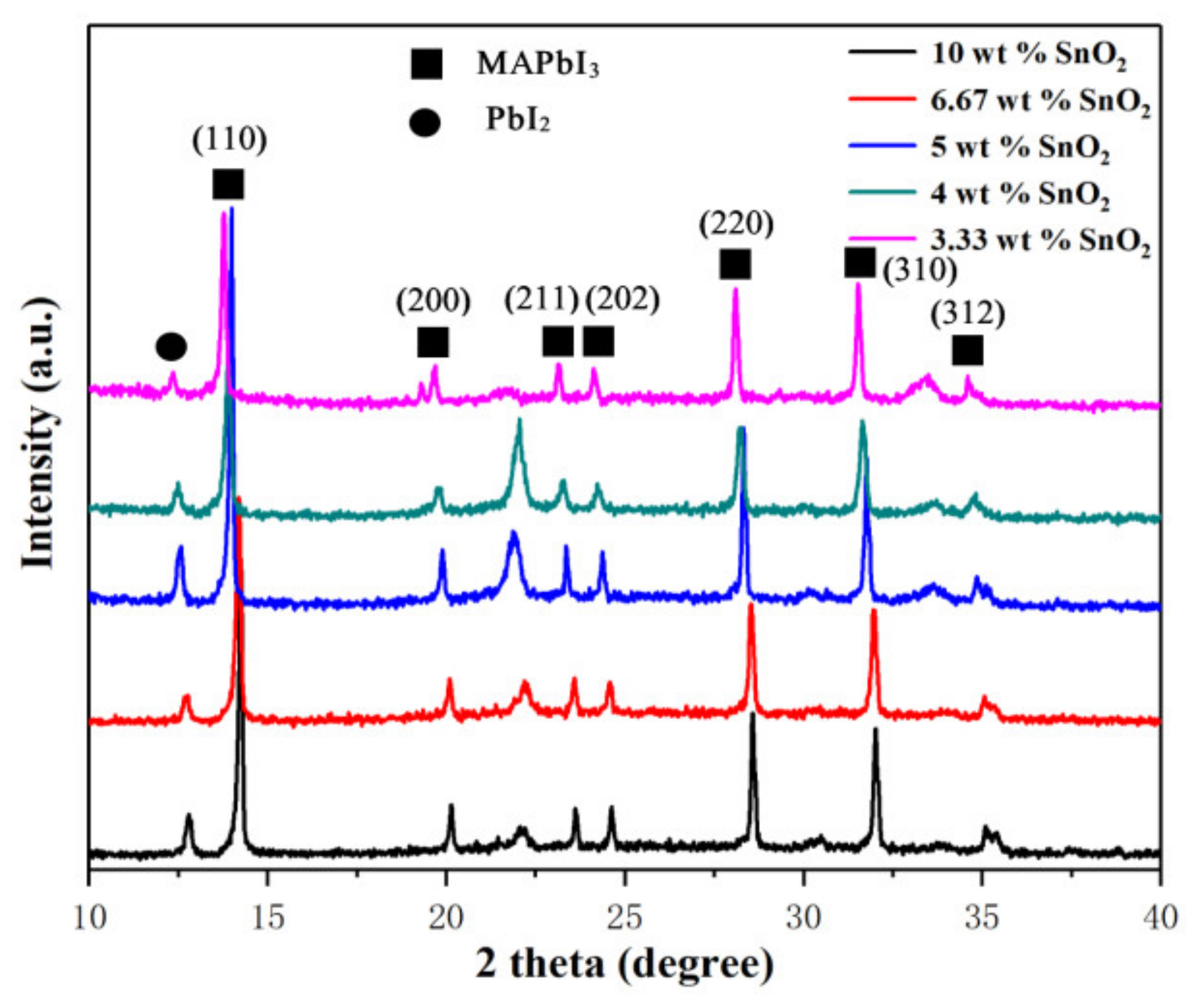
| Samples | Relative Intensity Ratio |
|---|---|
| 10 wt.% SnO2 | 0.18 |
| 6.67 wt.% SnO2 | 0.43 |
| 5 wt.% SnO2 | 0.47 |
| 4 wt.% SnO2 | 0.76 |
| 3.33 wt.% SnO2 | 0.76 |
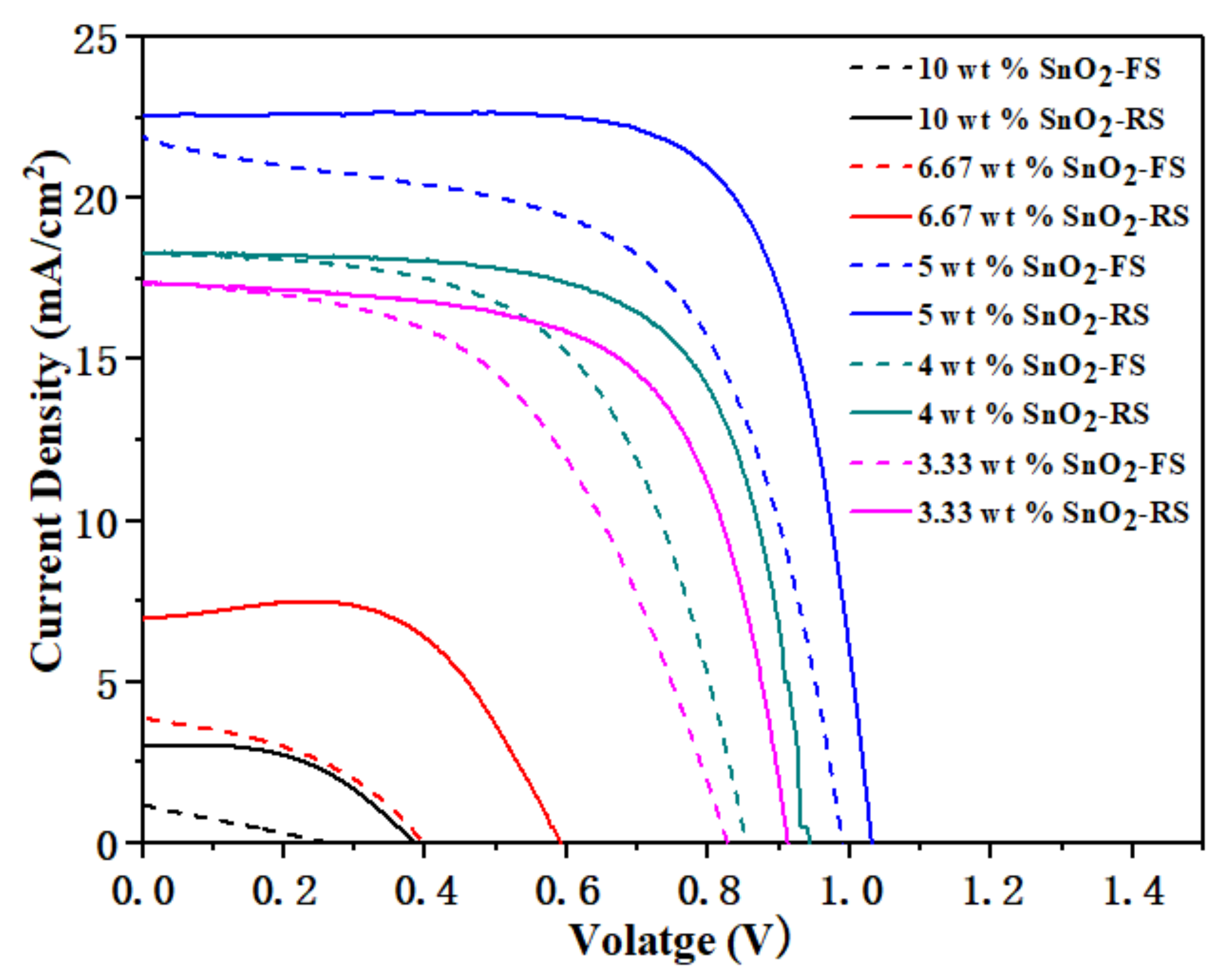
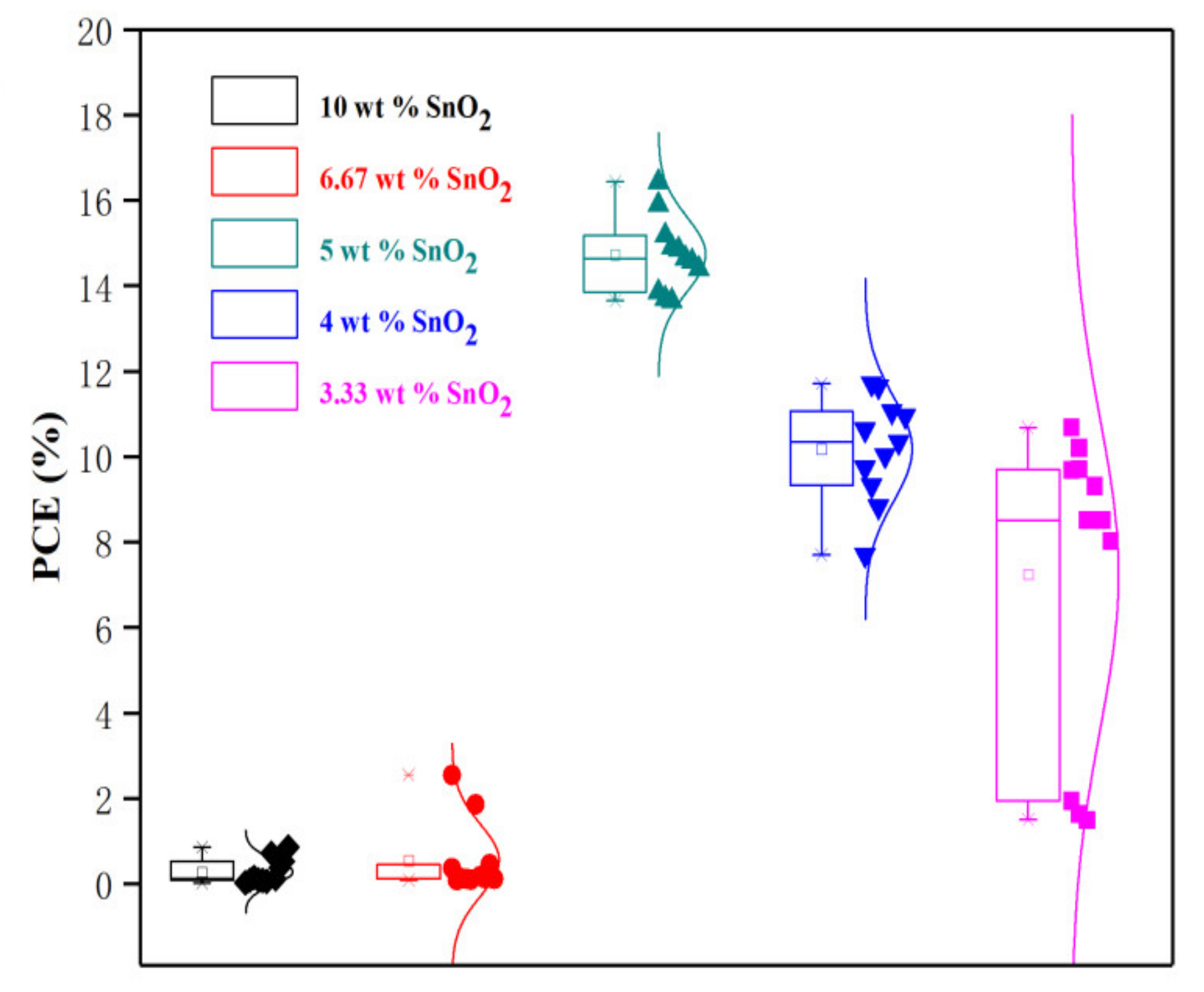
| Samples | Scanning Direction | VOC (V) | JSC (mA/cm2) | FF (%) | PCE (%) | HI |
|---|---|---|---|---|---|---|
| 10 wt.% SnO2 | FS | 0.28 | 1.06 | 28 | 0.08 | 0.91 |
| RS | 0.41 | 3.84 | 48 | 0.86 | ||
| 6.67 wt.% SnO2 | FS | 0.43 | 4.17 | 24 | 0.43 | 0.83 |
| RS | 0.59 | 6.96 | 62 | 2.55 | ||
| 5 wt.% SnO2 | FS | 0.99 | 21.93 | 59 | 12.90 | 0.23 |
| RS | 1.03 | 22.57 | 73 | 16.82 | ||
| 4 wt.% SnO2 | FS | 0.85 | 18.31 | 59 | 9.15 | 0.22 |
| RS | 0.94 | 18.33 | 68 | 11.71 | ||
| 3.33 wt.% SnO2 | FS | 0.87 | 15.70 | 60 | 8.19 | 0.23 |
| RS | 0.96 | 15.66 | 71 | 10.68 |
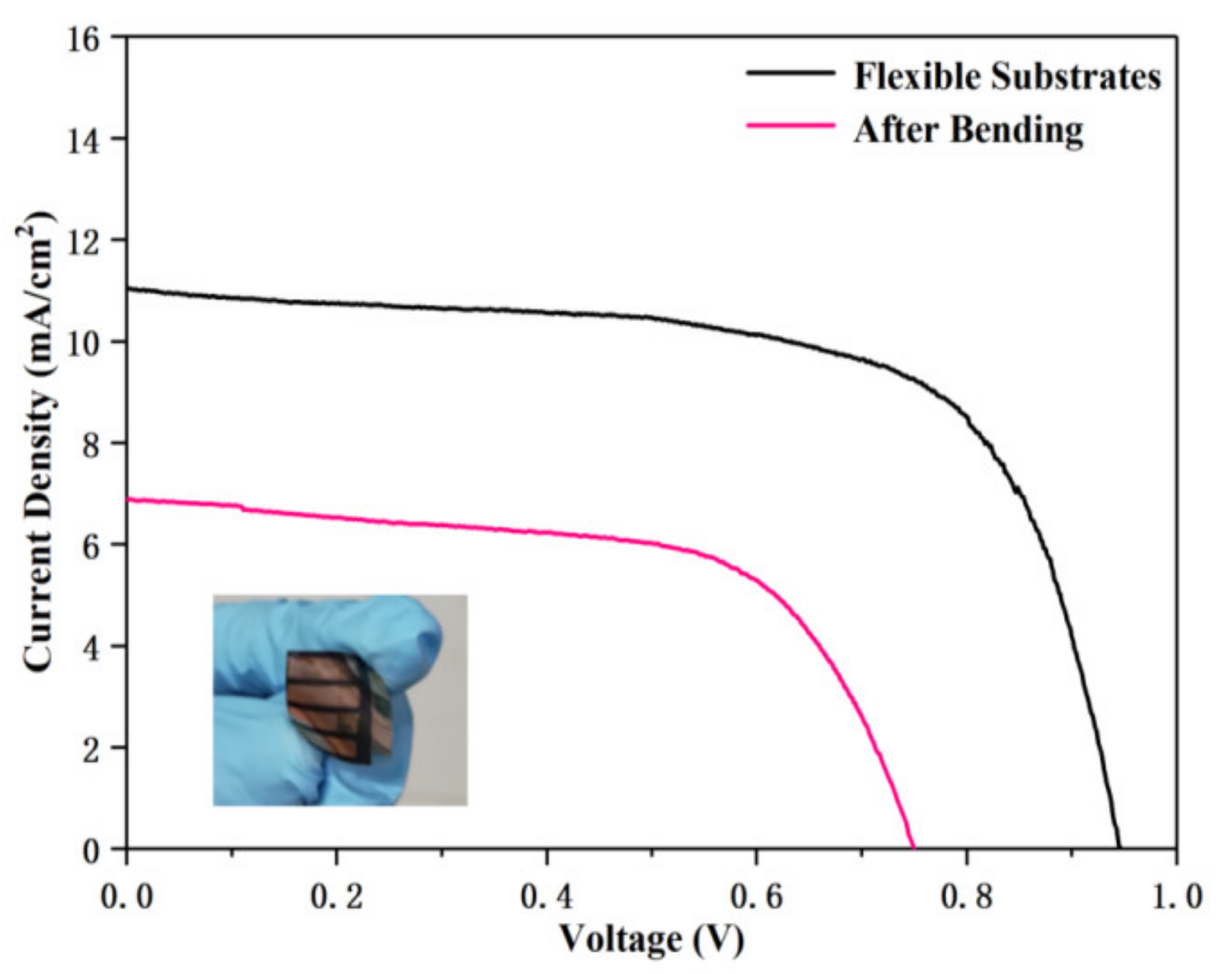
| Samples | PCE (%) | VOC (V) | JSC (mA/cm2) | FF (%) |
|---|---|---|---|---|
| Flexible Substrate | 7.00 | 0.95 | 11.03 | 67.00 |
| Bending (Radius of curvature is 5 mm) | 3.21 | 0.75 | 6.88 | 63.00 |
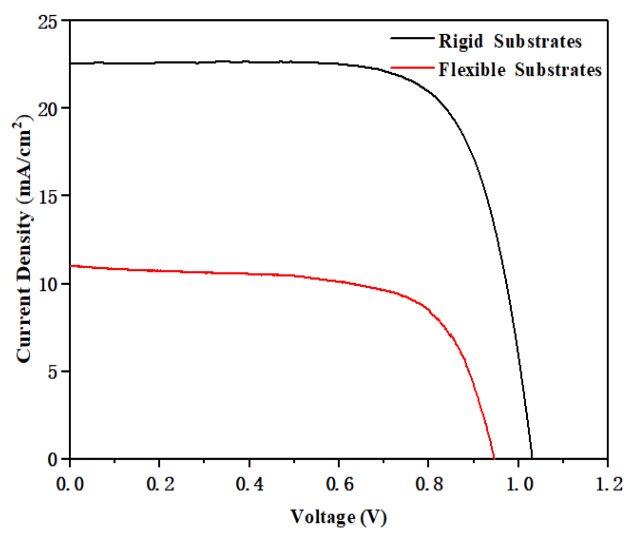
| Samples | PCE (%) | VOC (V) | JSC (mA/cm2) | FF (%) |
|---|---|---|---|---|
| Rigid Substrate | 16.82 | 1.03 | 22.57 | 73 |
| Flexible Substrate | 7.00 | 0.95 | 11.03 | 67 |
Publisher’s Note: MDPI stays neutral with regard to jurisdictional claims in published maps and institutional affiliations. |
© 2021 by the authors. Licensee MDPI, Basel, Switzerland. This article is an open access article distributed under the terms and conditions of the Creative Commons Attribution (CC BY) license (https://creativecommons.org/licenses/by/4.0/).
Share and Cite
Song, K.; Zou, X.; Zhang, H.; Zhang, C.; Cheng, J.; Liu, B.; Yao, Y.; Wang, X.; Li, X.; Wang, Y.; et al. Effect of SnO2 Colloidal Dispersion Solution Concentration on the Quality of Perovskite Layer of Solar Cells. Coatings 2021, 11, 591. https://0-doi-org.brum.beds.ac.uk/10.3390/coatings11050591
Song K, Zou X, Zhang H, Zhang C, Cheng J, Liu B, Yao Y, Wang X, Li X, Wang Y, et al. Effect of SnO2 Colloidal Dispersion Solution Concentration on the Quality of Perovskite Layer of Solar Cells. Coatings. 2021; 11(5):591. https://0-doi-org.brum.beds.ac.uk/10.3390/coatings11050591
Chicago/Turabian StyleSong, Keke, Xiaoping Zou, Huiyin Zhang, Chunqian Zhang, Jin Cheng, Baoyu Liu, Yujun Yao, Xiaolan Wang, Xiaotong Li, Yifei Wang, and et al. 2021. "Effect of SnO2 Colloidal Dispersion Solution Concentration on the Quality of Perovskite Layer of Solar Cells" Coatings 11, no. 5: 591. https://0-doi-org.brum.beds.ac.uk/10.3390/coatings11050591