
TiN/NbN Nanoscale Multilayer Coatings Deposited by High Power Impulse Magnetron Sputtering to Protect Medical-Grade CoCrMo Alloys

 ,
,
Abstract
:1. Introduction
2. Materials and Methods
2.1. TiN/NbN Nanoscale Multilayer Coating Design Strategy and Deposition Procedure
2.2. Characterisation Techniques
3. Results and Discussion
3.1. Coating Microstructure
3.2. Adhesion Strength of the Coatings
3.3. Mechanical and Tribological Properties
3.4. Fatigue Resistance
3.5. Fracture Toughness
3.6. Corrosion Properties
3.7. Inductively Coupled Plasma Mass Spectrometry (ICPMS)
4. Conclusions
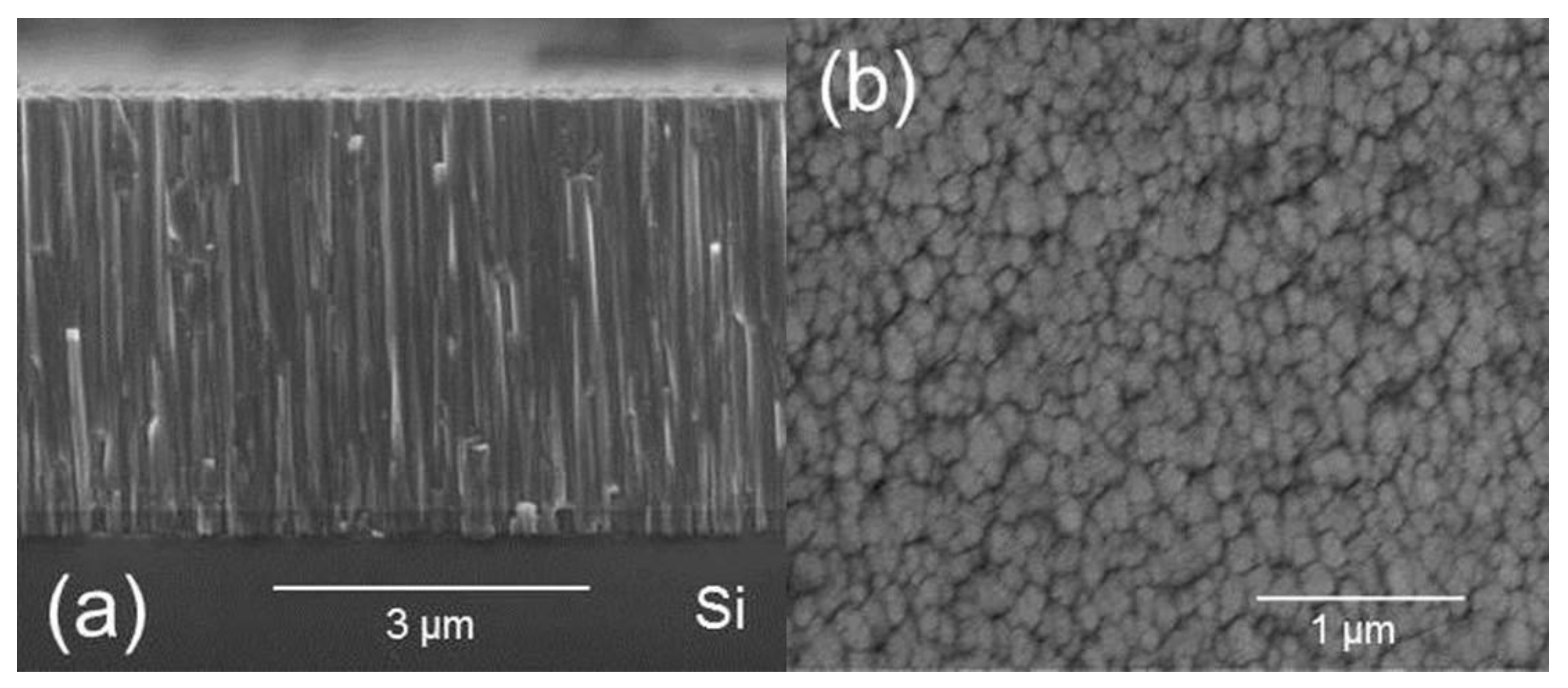
- TiN/NbN multilayer coatings were deposited on CoCrMo alloys by utilising mixed HIPIMS/UBM sputtering. Scratch tests revealed superior coating to substrate adhesion due to the HIPIMS etching prior to coating deposition. Scanning electron microscopy analysis showed that these coatings are extremely dense without any intercolumnar voids.
- Nanoindentation measurements showed enhanced coating hardness of 28 GPa as compared to 6 GPa of the uncoated alloy. Dry sliding pin on disc tests against the alumina ball showed enhanced tribological properties of the multilayer coating. The friction coefficient (µ) of 0.7 and wear coefficient (KC) of 1.4 × 10⁻¹⁴ m3·N−1·m−1 of the multilayer coating were significantly lower as compared to that of the bare material with µ of 0.83 and KC of 2.7 × 10⁻¹⁴ m3·N−1·m−1.
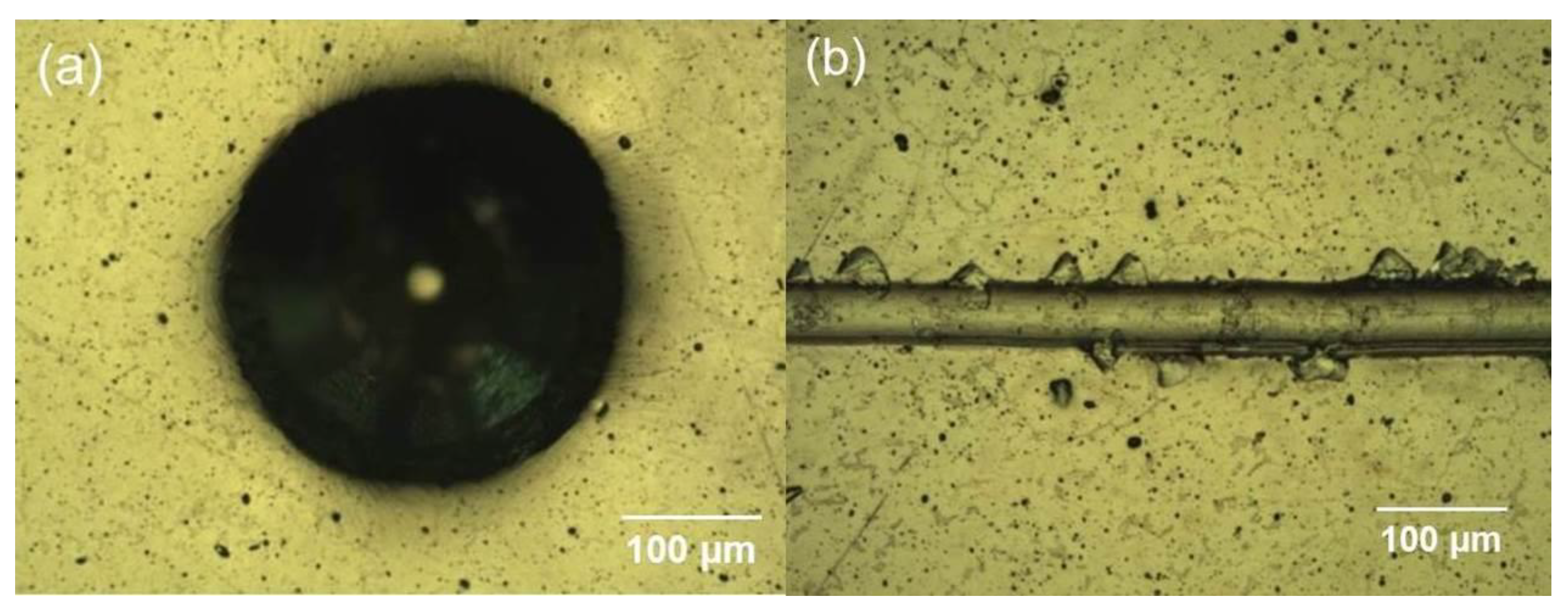
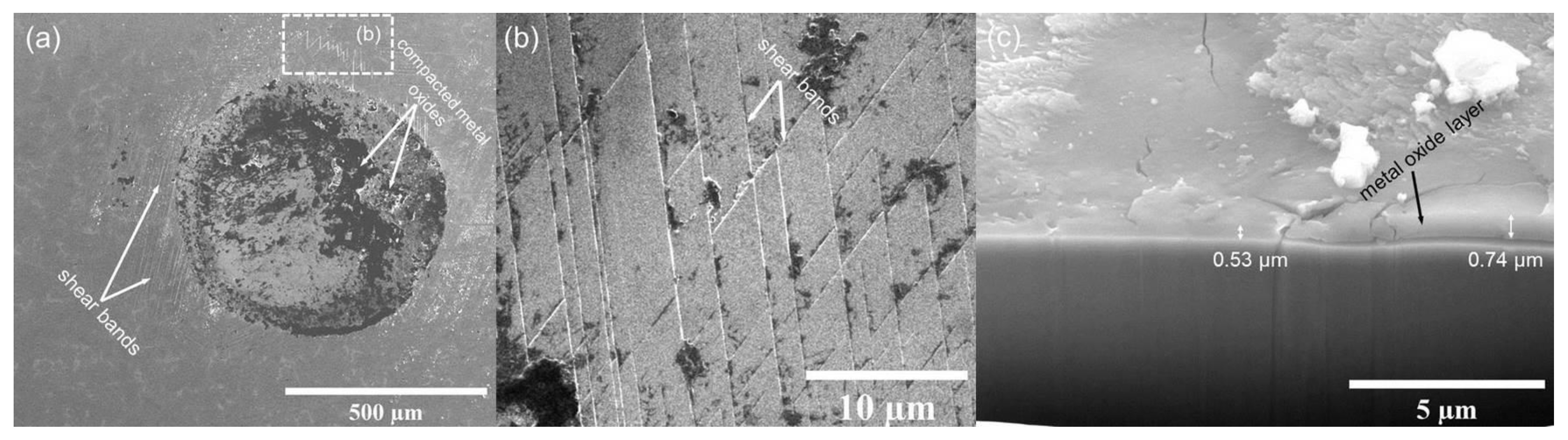
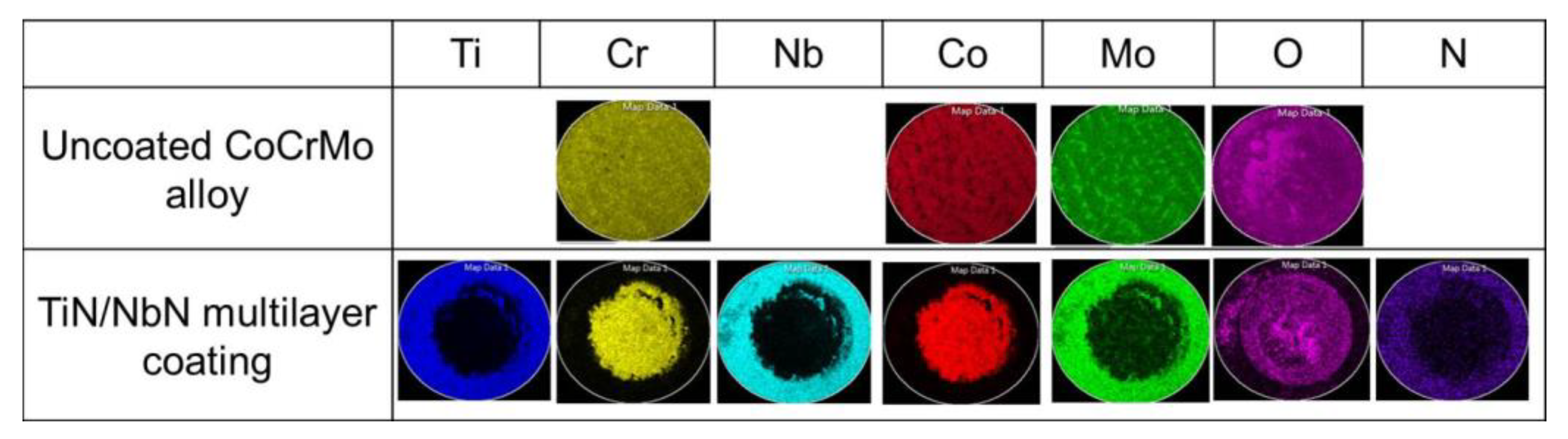
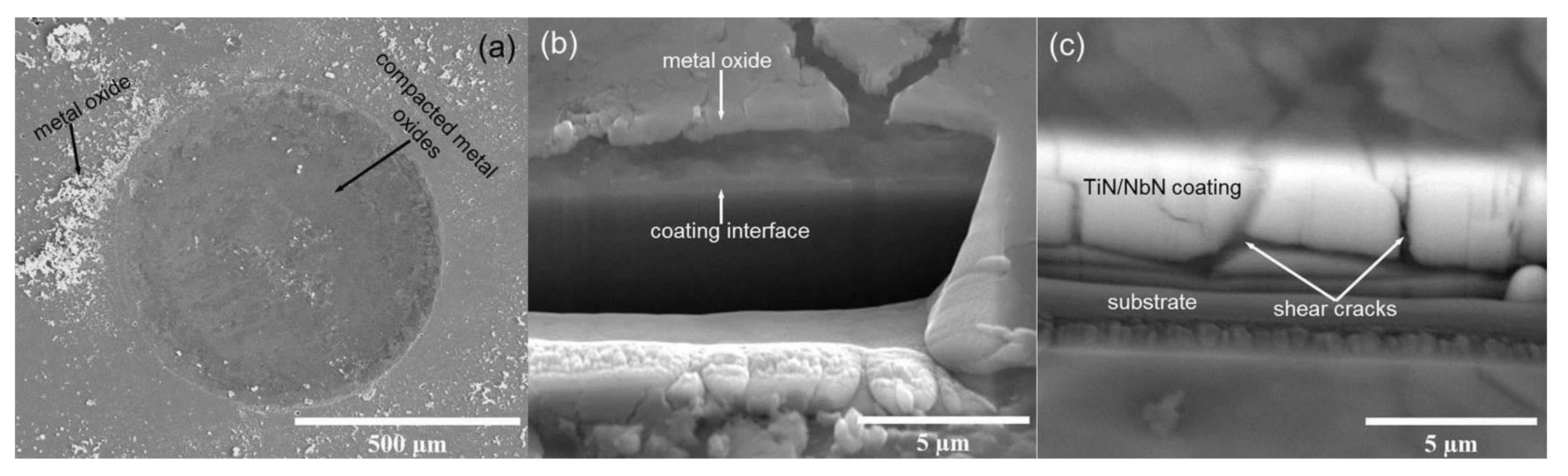
- Detailed EDX analysis together with FIB cross-section investigation of the impact crater generated on coated alloy revealed that that the degradation mechanism of the coating was similar to that of the base material which is oxidation behaviour, and the coating was still intact inside the crater around the damaged area even after 1 million impacts, confirming the excellent coating to substrate bonding strength.
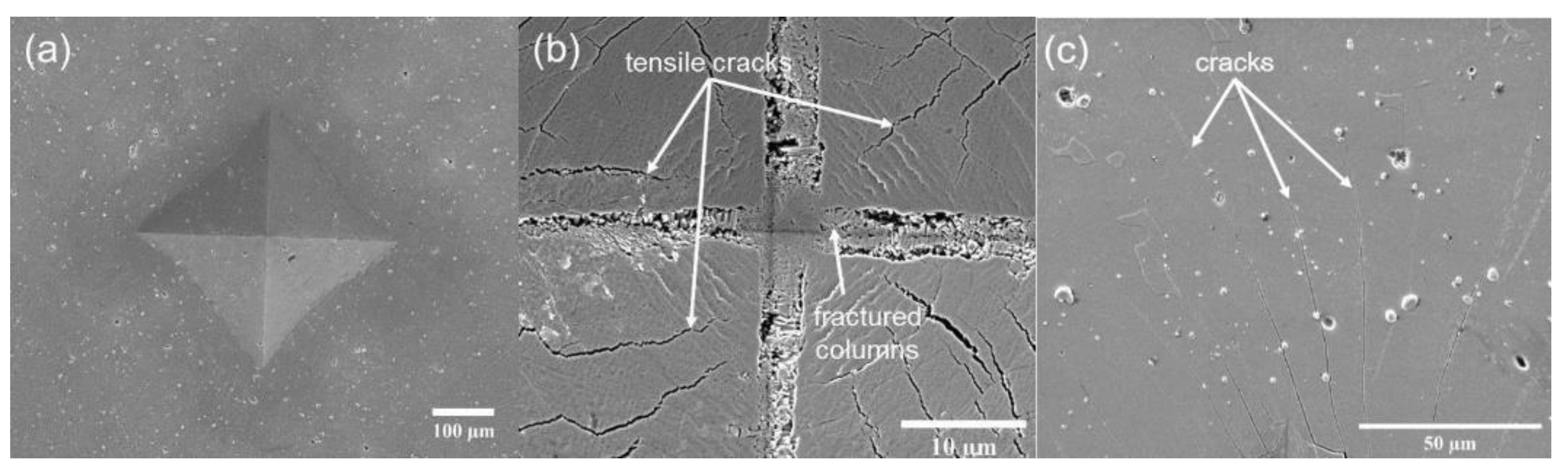
- Fatigue analysis of the coated alloy showed that the columns of the coating were pressed during the loading which led to complete damage of the area and the formation of tensile cracks which originated through flow of tensile stress formed at the interface of the coating and substrate.
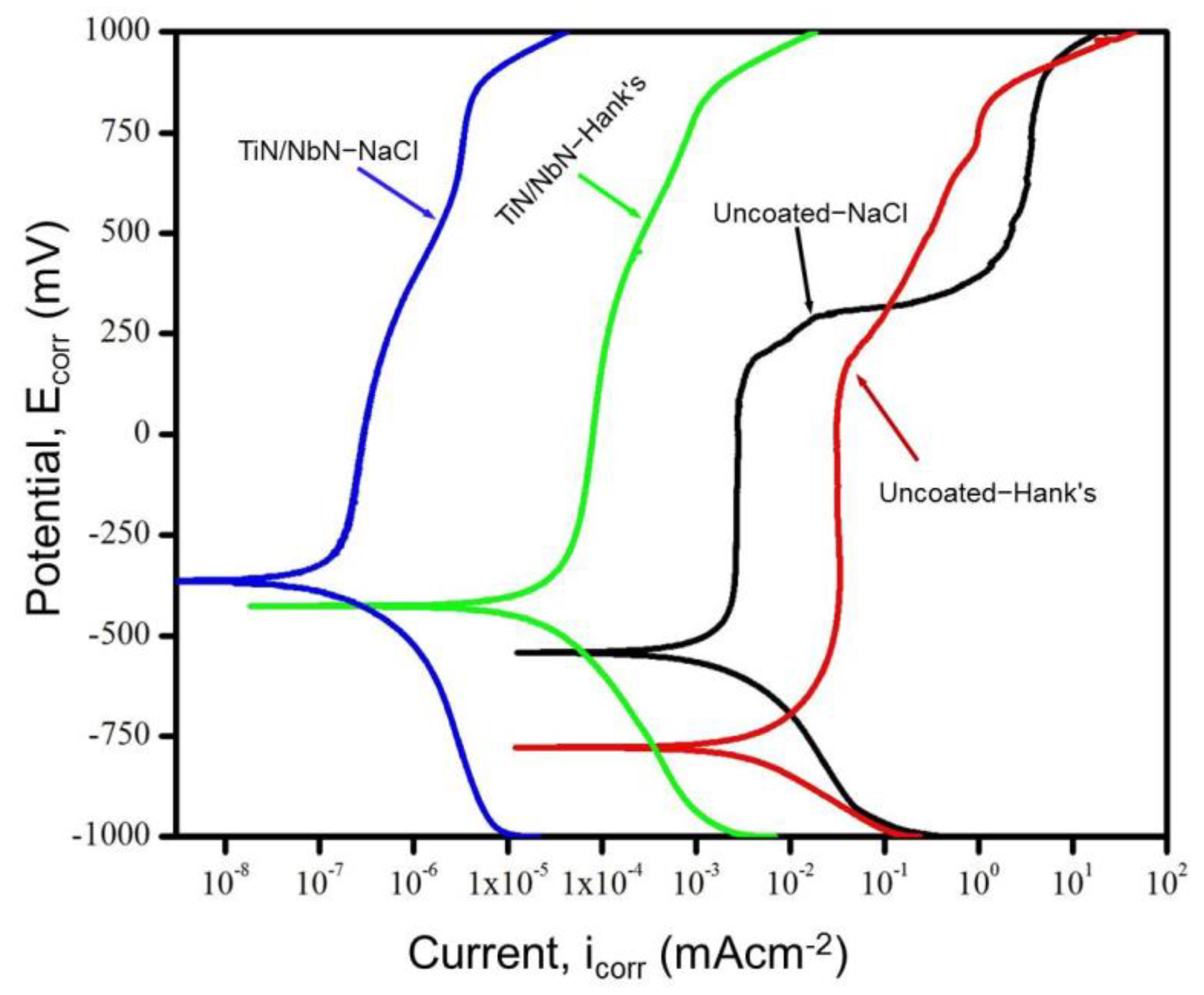
- Potentiodynamic polarisation tests in NaCl and Hank’s solutions revealed the clear passivation behaviour, several orders of magnitude lower corrosion currents, and high pitting potentials of the coating, which guarantee excellent protection to the base alloy in such aggressive environments.
- Inductively coupled plasma mass spectrometry analysis of the coated sample corroded in Hank’s solution revealed that the leaching of harmful metal ions from the base material was reduced to below the detection limit of the technique, thus demonstrating the high barrier properties of the coating.
Author Contributions
Funding
Institutional Review Board Statement
Informed Consent Statement
Data Availability Statement
Acknowledgments
Conflicts of Interest
References
- Okazaki, Y.; Gotoh, E. Comparison of metal release from various metallic biomaterials in vitro. Biomaterials 2005. [Google Scholar] [CrossRef] [PubMed]
- Wapner, K.L. Implications of metallic corrosion in total knee arthroplasty. Clin. Orthop. Relat. Res. 1991, 271, 12–20. [Google Scholar] [CrossRef]
- McGregor, D.B.; Baan, R.A.; Partensky, C.; Rice, J.M.; Wilbourn, J.D. Evaluation of the carcinogenic risks to humans associated with surgical implants and other foreign bodies—A report of an IARC Monographs Programme Meeting. Eur. J. Cancer 2000, 36, 307–313. [Google Scholar] [CrossRef]
- Wisbey, A.; Gregson, P.J.; Tuke, M. Application of PVD TiN coating to Co–Cr–Mo based surgical implants. Biomaterials 1987, 8. [Google Scholar] [CrossRef]
- Pham, V.H.; Yook, S.W.; Lee, E.J.; Li, Y.; Jeon, G.; Lee, J.J.; Kim, H.E.; Koh, Y.H. Deposition of TiN films on Co–Cr for improving mechanical properties and biocompatibility using reactive DC sputtering. J. Mater. Sci. Mater. Med. 2011. [Google Scholar] [CrossRef] [PubMed]
- Harman, M.K.; Banks, S.A.; Andrew Hodge, W. Wear analysis of a retrieved hip implant with titanium nitride coating. J. Arthroplast. 1997. [Google Scholar] [CrossRef]
- Neumann, H.G.; Beck, U.; Drawe, M.; Steinbach, J. Multilayer systems for corrosion protection of stainless steel implants. Surf. Coat. Technol. 1998. [Google Scholar] [CrossRef]
- Hamelynck, K.J.; Woering, R.G. Ceramic Surface Engineered Metal-on-Metal Hips System for Total Hip Arthroplasty and Resurfacing Hip Arthroplasty. ACCIS White Pap. 2009. Available online: https://silo.tips/download/ceramic-surface-engineered-metal-on-metal-hips-system-for-total-hip-arthroplasty (accessed on 14 April 2021).
- Hovsepian, P.E.; Ehiasarian, A.P.; Purandare, Y.; Sugumaran, A.A.; Marriott, T.; Khan, I. Development of superlattice CrN/NbN coatings for joint replacements deposited by high power impulse magnetron sputtering. J. Mater. Sci. Mater. Med. 2016, 27, 1–10. [Google Scholar] [CrossRef] [PubMed]
- Ehiasarian, A.P. Fundamentals and Applications of HIPIMS. In Plasma Surface Engineering Research and Its Practical Applications; Wei, R., Ed.; Research Signpost: Kerala, India, 2007; ISBN 978-81-308-0257-2. [Google Scholar]
- Ehiasarian, A.P.; Vetushka, A.; Gonzalvo, Y.A.; Sáfrán, G.; Székely, L.; Barna, P.B. Influence of high power impulse magnetron sputtering plasma ionization on the microstructure of TiN thin films. J. Appl. Phys. 2011, 109, 104314. [Google Scholar] [CrossRef]
- Ehiasarian, A.P.; Wen, J.G.; Petrov, I. Interface microstructure engineering by high power impulse magnetron sputtering for the enhancement of adhesion. J. Appl. Phys. 2007. [Google Scholar] [CrossRef]
- Ehiasarian, A.; Hovsepian, P.; Munz, W. Combined Coating Process Comprising Magnetic Field-Assisted, High Power, Pulsed Cathode Sputtering and an Unbalanced Magnetron. U.S. Patent 7,081,186, 25 July 2006. [Google Scholar]
- Reinhard, C.; Ehiasarian, A.P.; Hovsepian, P.E. CrN/NbN superlattice structured coatings with enhanced corrosion resistance achieved by high power impulse magnetron sputtering interface pre-treatment. Thin Solid Film. 2007, 515, 3685–3692. [Google Scholar] [CrossRef]
- Hovsepian, P.E.; Sugumaran, A.A.; Purandare, Y.; Loch, D.A.L.; Ehiasarian, A.P. Effect of the degree of high power impulse magnetron sputtering utilisation on the structure and properties of TiN films. Thin Solid Film. 2014, 562. [Google Scholar] [CrossRef] [Green Version]
- Hovsepian, P.E.; Ehiasarian, A.P. Six strategies to produce application tailored nanoscale multilayer structured PVD coatings by conventional and high power impulse magnetron sputtering (HIPIMS). Thin Solid Film. 2019, 688. [Google Scholar] [CrossRef]
- Hovsepian, P.E.; Münz, W.-D. Synthesis, Structure, and Applications of Nanoscale Multilayer/Superlattice Structured PVD Coatings. In Nanostructured Coatings; Cavaleiro, A., De Hosson, J.T.M., Eds.; Springer: New York, NY, USA, 2006; pp. 555–644. ISBN 978-0-387-48756-4. [Google Scholar]
- Ehiasarian, A.P.; Tietema, R.; Bugyi, R.; Klimczak, A.; Hovsepian, P.E.; Doerwald, D. A Vacuum Treatment Apparatus, a Bias Power Supply and a Method of Operating a Vacuum Treatment Apparatus. U.S. Patent 20,100,025,230 A1, 4 February 2010. [Google Scholar]
- Zhang, S.; Sun, D.; Fu, Y.; Du, H. Toughness measurement of thin films: A critical review. Surf. Coat. Technol. 2005, 198. [Google Scholar] [CrossRef]
- Ehiasarian, A.P.; New, R.; Münz, W.D.; Hultman, L.; Helmersson, U.; Kouznetsov, V. Influence of high power densities on the composition of pulsed magnetron plasmas. Vacuum 2002. [Google Scholar] [CrossRef]
- Türkan, U.; Öztürk, O.; Eroǧlu, A.E. Metal ion release from TiN coated CoCrMo orthopedic implant material. Surf. Coat. Technol. 2006, 200, 5020–5027. [Google Scholar] [CrossRef] [Green Version]
- Bell, T.; Dong, H.; Sun, Y. Realising the potential of duplex surface engineering. Tribol. Int. 1998, 31, 127–137. [Google Scholar] [CrossRef]
- Fu, K.; Chang, L.; Zheng, B.; Tang, Y.; Yin, Y. Analysis on cracking in hard thin films on a soft substrate under Berkovich indentation. Vacuum 2015, 112. [Google Scholar] [CrossRef]


| Compound | Molecular Weight (g/mol) |
|---|---|
| NaCl | 58.44 |
| KCl | 74.55 |
| CaCl2 | 110.98 |
| MgSO4·7H2O | 246.47 |
| MgCl2·6H2O | 203.30 |
| Na2HPO4·2H2O | 177.99 |
| Sample | Thickness (µm) | Microhardness (HK) | Nanohardness (GPa) | Young’s Modulus (GPa) | Bilayer Thickness (nm) |
|---|---|---|---|---|---|
| CoCrMo substrate | - | 900 | 6 ± 1 | 215 | - |
| TiN/NbN multilayer coating | 4.2 | 3100 | 28 ± 2 | 390 | 3 |
| Sample | Co | Cr | Mo | Nb | Ti |
|---|---|---|---|---|---|
| Uncoated CoCrMo substrate | 0.26 | 0.18 | 0 | 0 | 0 |
| TiN/NbN multilayer coating | 0 | 0 | 0 | 0.53 | 0.14 |
Publisher’s Note: MDPI stays neutral with regard to jurisdictional claims in published maps and institutional affiliations. |
© 2021 by the authors. Licensee MDPI, Basel, Switzerland. This article is an open access article distributed under the terms and conditions of the Creative Commons Attribution (CC BY) license (https://creativecommons.org/licenses/by/4.0/).
Share and Cite
Sugumaran, A.A.; Purandare, Y.; Shukla, K.; Khan, I.; Ehiasarian, A.; Hovsepian, P. TiN/NbN Nanoscale Multilayer Coatings Deposited by High Power Impulse Magnetron Sputtering to Protect Medical-Grade CoCrMo Alloys. Coatings 2021, 11, 867. https://0-doi-org.brum.beds.ac.uk/10.3390/coatings11070867
Sugumaran AA, Purandare Y, Shukla K, Khan I, Ehiasarian A, Hovsepian P. TiN/NbN Nanoscale Multilayer Coatings Deposited by High Power Impulse Magnetron Sputtering to Protect Medical-Grade CoCrMo Alloys. Coatings. 2021; 11(7):867. https://0-doi-org.brum.beds.ac.uk/10.3390/coatings11070867
Chicago/Turabian StyleSugumaran, Arunprabhu Arunachalam, Yashodhan Purandare, Krishnanand Shukla, Imran Khan, Arutiun Ehiasarian, and Papken Hovsepian. 2021. "TiN/NbN Nanoscale Multilayer Coatings Deposited by High Power Impulse Magnetron Sputtering to Protect Medical-Grade CoCrMo Alloys" Coatings 11, no. 7: 867. https://0-doi-org.brum.beds.ac.uk/10.3390/coatings11070867