1. Introduction
There is always a continuous demand for higher operating temperatures for gas turbine engines in order to improve fuel efficiency and engine thrust. The temperature capability of current Ni-base superalloys has reached their limit [
1]. Silicon carbide ceramic matrix composites (SiC/SiC CMCs) have been considered as the material for next-generation aircraft engine components due to their excellent high-temperature strength and lower specific weight [
1,
2,
3]. Due to the high heat resistance, CMCs components require less air cooling and therefore enable engines to run hotter and more efficiently at higher thrust. Recently, silicon carbide-based CMCs have been successfully implemented in hot section components of LEAP and GE
9x aircraft engines [
3]. One key issue with SiC/SiC CMCs is that they suffer from recession in steam environments due to the volatilization of silica scale by water vapor, and so CMCs components must be protected with environmental barrier coatings (EBCs) to prevent recession in engine operating environments. Current EBCs consist of a silicon bond coat and oxide based upper layers such as mullite, barium–strontium–aluminum–silicates (BSAS), and rare earth silicates [
2,
4,
5,
6]. Among them, Yb
2Si
2O
7 disilicate is the leading candidate for environmental barrier coatings (EBCs) for SiC-based CMCs due to its high-temperature phase stability and excellent thermal expansion match with SiC [
5,
6,
7,
8].
The air plasma spray process (APS) has been widely used for the deposition of EBCs due to its relatively low cost and high deposition rates [
2,
5,
7,
9]. EBCs coatings such as mullite [
4], rare earth silicates [
6,
9], and BSAS (BaO·SrO-Al
2O
3-2SiO
2) [
10] have been deposited using the APS process. In contrast to the coating deposition in air atmosphere, a plasma spray torch can also be operated in a controlled and low-pressure atmosphere. The reduced pressure compared to atmospheric conditions enlarges the plasma plume from approximately 50 to 500 mm in length and from 10 to 40 mm in diameter. A larger plume results in a bigger spray spot. Therefore, particle velocities and temperatures are more homogenously distributed over the cross-section of the plume. This allows for coatings with a homogenous coating microstructure, even on parts with complex geometries—such as engine blades and vanes. In addition, due to the reduced pressure, the plasma gas velocities as well as the resultant particle velocities are much higher than those in APS. Higher particle velocities at impact are favorable to produce denser coatings, which is a critical property for hermetic EBCs. Therefore, it is of significant value to investigate and compare the properties of EBCs deposited using APS and LPPS processes.
In our previous work, Yb
2Si
2O
7/Si EBCs had been deposited using the LPPS process [
11]. The isothermal oxidation kinetics of LPPS EBCs in a steam environment was also evaluated. However, the thermal cycling behavior of LPPS EBCs in steam has not been investigated.
In this study, Yb2Si2O7/Si EBCs were produced by APS and LPPS processes. The phase composition, microstructure, and bonding strength of APS and LPPS EBCs were investigated. The thermal cycling life as well as TGO growth behavior of these coatings in air and in water vapor conditions were also evaluated.
2. Experimental Procedures
Metco 4810 Si powder with a size distribution of −75/+15 µm was used for bond coat deposition and Metco 6157 Yb2Si2O7 powder (≈3 vol.% Yb2SiO5 minor phase) with a size distribution of −90/+11 µm was used for top coat deposition. Both of them are produced by Oerlikon Metco (Westbury, NY, USA). The Yb2Si2O7/Si EBCs were deposited onto ϕ 25.4 mm × 3 mm Hexoloy™ μ-SiC substrates (Saint Gobain Ceramics, Niagara Falls, NY, USA) using APS and LPPS process, respectively. Before coating deposition, SiC substrate was grit basted using 24 mesh SiC grits. For APS EBCs, the coatings were sprayed using the SinplexPro plasma torch. For LPPS EBCs, the coatings were sprayed using an O3CP torch in a 30 mbar chamber pressure. Both APS and LPPS EBC consist of a ≈200 µm thick top coat and ≈175 µm thick Si bond coat. Only one side of the SiC substrate was coated.
All of the as-sprayed coatings were further annealed at 1300 °C for 10 h under ambient conditions. X-ray diffraction (XRD, Ultima IV, Rigaku Corporation, Tokyo, Japan) analysis was carried out on the as-sprayed and annealed coatings. The relative phase composition of the annealed coating was analyzed semi-quantitively by comparing the crystalline peak intensities [
12]. Standard metallographic practices were used to polish the coatings cross-sections, and their microstructures were characterized using scanning electron microscopy (SEM, Hitachi S-3400N, Hitachi America, Ltd., Tarrytown, NY, USA). The coating porosity was measured on the cross-sections of as-prepared coatings using the image analysis method. Coating bonding strength was measured according to ASTM C633 standard test method.
The EBCs thermal cycle durability was evaluated in air atmosphere and steam atmosphere at 1316 °C, respectively. A thermal cycling test in the ambient conditions was performed at 1316 °C using a CM™ rapid temperature furnace (CM Bloomfield, Bloomfield, NJ, USA). The cycling conditions consisted of three steps: a 10-min heating up to test temperature of 1316 °C, a 40 min hold at the test temperature, and a 10 min cooling that brought the substrate temperature to around 100 °C. Please note that the cycle start and end temperatures were not room temperature, to maintain the cycling time. The conditions for a similar test in steam were different. The thermal incursion had a 5 min heat-up to the test temperature of 1316 °C, a 60 min hold at the test temperature, and a 15 min air cooling until the substrate temperature reached ~100 °C. In both the air and steam furnace cycle testing, the samples were pulled out of the furnace hot zones to allow them to cool under air environment. To create steam environment, a controlled mixture of water vapor and air is introduced to the furnace. The steam consisted of ≈90 vol.% H2O (g) + ≈10 vol.% air. The gas velocity is ≈4 cm/s at the hot zone of the furnace chamber. A total of eight samples were cycled for each system. One sample was removed after 200, 400, 600, and 800 cycles for TGO growth rate evaluation. A total of 1000 cycles were performed. The coating was considered to be at failure when spallation was observed. For these thermal cycled samples, in order to avoid damage during metallography sample preparation, coatings were sectioned with a slow diamond saw cutting speed of 0.01 mm/s. Then, the cut samples were mounted and polished for SEM characterization.
3. Results and Discussion
3.1. Microstructure and Phase Composition
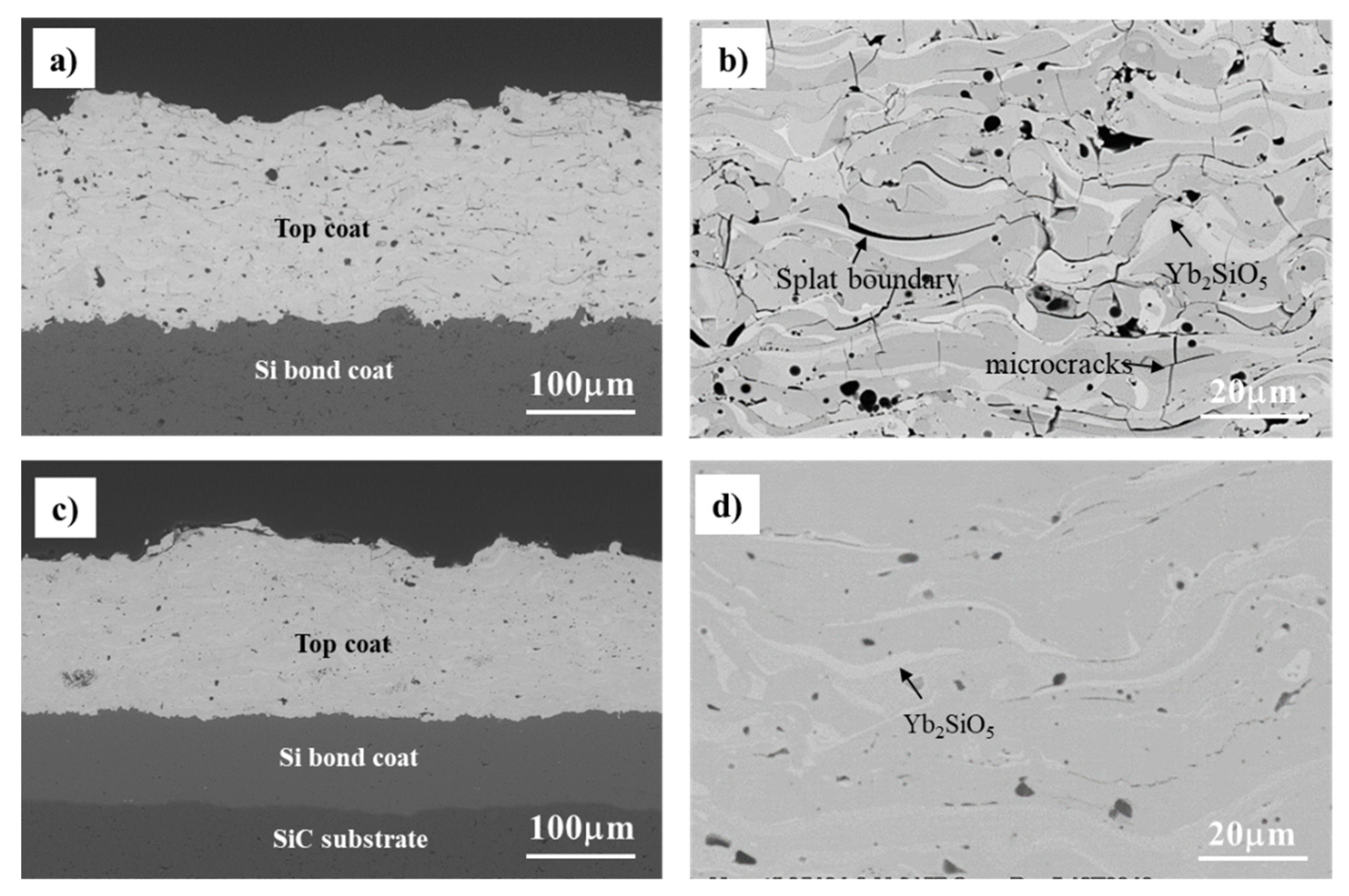
The cross-sections of APS and LPPS Yb
2Si
2O
7/Si coating microstructures are shown in
Figure 1. Both the Si bond coat and Yb
2Si
2O
7 top coat exhibit dense microstructures with measured porosity less than 5%. High magnification analysis shows that the APS Yb
2Si
2O
7 coating contains some microcracks and splats boundaries (
Figure 1b). In contrast, there are no microcracks observed in the LPPS Yb
2Si
2O
7 coatings (
Figure 1d). The LPPS Yb
2Si
2O
7 coating is ≈2% denser than the APS Yb
2Si
2O
7 coating. A previous study indicated that the particle velocity in the LPPS process is about four to six times faster than the APS process [
13]. The high particle velocity during impingement on the substrate will result in better adhesion between molten splats, which results in a denser coating in the LPPS process. Two phase microstructures, with dark (Yb
2Si
2O
7) and bright (Yb
2SiO
5) appearances, are evident from the contrast difference in backscatter electrons mode of SEM images. These two phases can be found in both APS and LPPS Yb
2Si
2O
7 coatings. The amount of bright phase (Yb
2SiO
5) in the LPPS coating is much less than that in the APS coating.
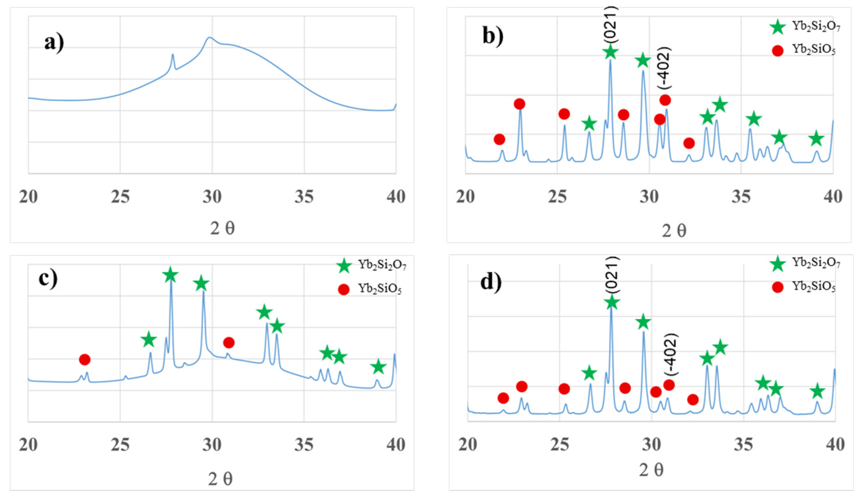
Figure 2 shows the XRD patterns of as-sprayed and annealed APS and LPPS Yb
2Si
2O
7 coatings. The as-sprayed APS coating is mainly composed of amorphous phases (
Figure 2a). In contrast, the LPPS coating is composed of a mixture of amorphous phases, crystalline Yb
2Si
2O
7 phase, as well as a small amount of crystalline Yb
2SiO
5 phase (
Figure 2c). The phase difference can be attributed to the coating deposition temperature difference in APS and LPPS processes. In the LPPS process, the coating surface temperature is ≈900 °C (recorded by pyrometer), which is significantly higher than that in the APS process (≈100 °C). The higher deposition temperature promotes some degree of in situ crystallization of solidifying particles. After 1300 °C/10 h heat treatment, the amorphous phase transforms to crystalline Yb
2Si
2O
7 and Yb
2SiO
5 phases in both APS and LPPS coatings (
Figure 2b,d). The appearance of the Yb
2SiO
5 phase in both APS and LPPS coatings can be attributed to SiO
2 evaporation loss from the molten particle in the high-temperature plasma plume.
The relative phase content of Yb
2SiO
5 and Yb
2Si
2O
7 in the annealed coatings was estimated by the intensity ratio of the (−402) and (021) primary diffraction peaks corresponding to Yb
2SiO
5 and Yb
2Si
2O
7 phases, respectively [
12]. The APS coating contains about 32.8 vol.% Yb
2SiO
5 and 67.2 vol.% Yb
2Si
2O
7 phases, while the LPPS coating contains 15.5 vol.% Yb
2SiO
5 and 84.5 vol.% Yb
2Si
2O
7 phases. Some of the Yb
2SiO
5 phases in both the APS and LPPS coatings are likely from the feedstock powders which contain ≈3 vol.% Yb
2SiO
5. The significant difference in the amount of Yb
2SiO
5 phase can be attributed to the very different particle melting states (e.g., particle temperature and velocity) in APS and LPPS Yb
2Si
2O
7 coating deposition. Since the particle velocity in the APS process is four to six times slower compared to that in the LPPS process [
13], it is estimated that the particle dwelling time in the APS process is ≈1.5 times that in the LPPS process. The longer dwelling time will result in more SiO
2 evaporation in the APS process.
3.2. Bonding Strength
The bonding strength of APS and LPPS Yb
2Si
2O
7/Si coatings were measured. The APS Yb
2Si
2O
7/Si coating has a bonding strength of 17.6 ± 1.6 MPa, while the LPPS Yb
2Si
2O
7/Si coating has a bonding strength of 29.1 ± 0.75 MPa. The bonding strength of LPPS EBCs is about 65% higher than that of APS EBCs. The cross-section microstructures after the bonding strength test are shown in
Figure 3. Both APS and LPPS Yb
2Si
2O
7/Si coatings primarily failed at the interface between the top coat and bond coat, with the observation that LPPS coatings had some degree of cohesive failure, while APS coatings were more similar to classic bond coat–top coat failure. In both the cases, SEM observations revealed that the Si bond coat has a strong adherence to the substrate. It had been reported [
14] the splat–substrate and inter-splat contact is dramatically improved at higher deposition temperatures, leading to reduced porosity and increased adhesion strength. The deposition temperature in the LPPS process (≈900 °C) is significantly higher than that in the APS process (≈100 °C); thus, it can be expected that the inter-splat bonding as well as the splat–silicon bonding will be improved in LPPS EBCs compared to that in APS EBCs. In addition, the higher kinetic energy due to the higher particle velocity in LPPS EBCs will further enhance the adhesion between splats and the silicon bond coat. Therefore, a higher bonding strength was observed in the LPPS EBCs.
3.3. Thermal Cycle Behavior in Air
A furnace cycle test (FCT) in air at 1316 °C was performed, and the test ran for 900 cycles (≈600 h hot time at 1316 °C). There were no coatings spallation/failure for both APS and LPPS Yb
2Si
2O
7/Si EBCs after 900 cycles. Both APS and LPPS Yb
2Si
2O
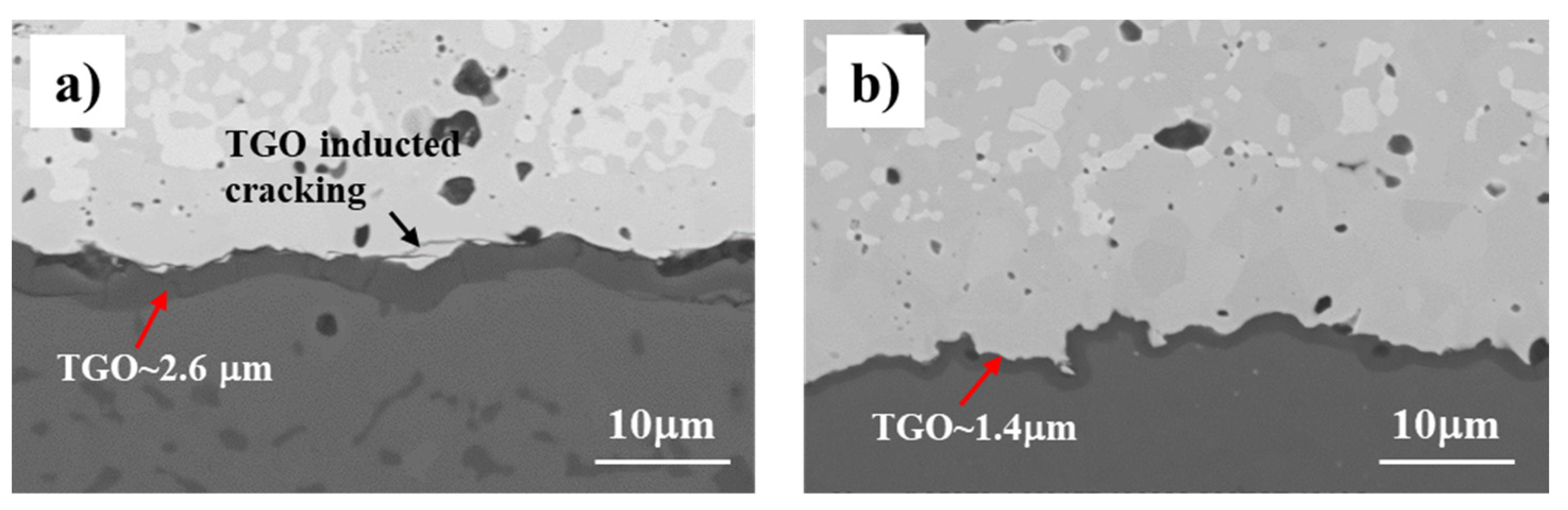
7/Si EBCs showed excellent thermal cycle behavior in air atmosphere. The coating cross-section microstructures after 900 FCT cycles are shown in
Figure 4. A thin layer of thermally grown oxides (TGO) formed at the Yb
2Si
2O
7/Si interface. The average TGO thickness for APS EBCs is about 2.6 µm, while it is about 1.4 µm for LPPS EBCs. In the APS EBCs, horizontal microcracks are observed between the TGO and top coat, and vertical microcracks are also shown in the TGO layer. In contrast, there are no microcracks observed at the top coat and TGO interface in the LPPS EBCs. The LPPS top coat continued to adhere very well to the TGO/Si bond coat.
3.4. Thermal Cycle Life in Steam
Both APS and LPPS EBCs were also thermally cycled in 90 vol.% H
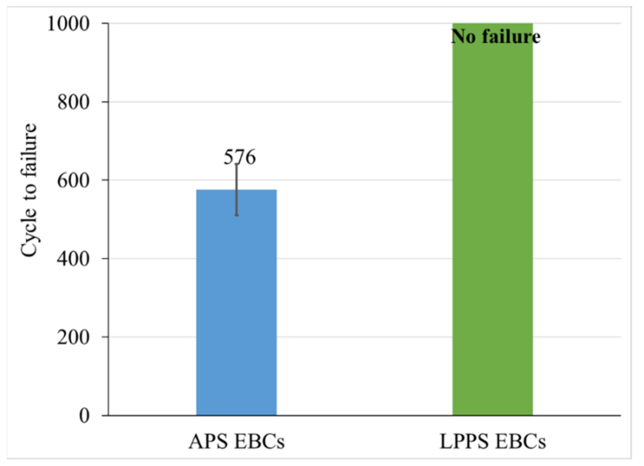
2O + 10 vol.% air environment at 1316 °C. APS EBCs had an average lifetime of 576 ± 65 cycles, while there was no failure for LPPS EBCs after 1000 cycles (
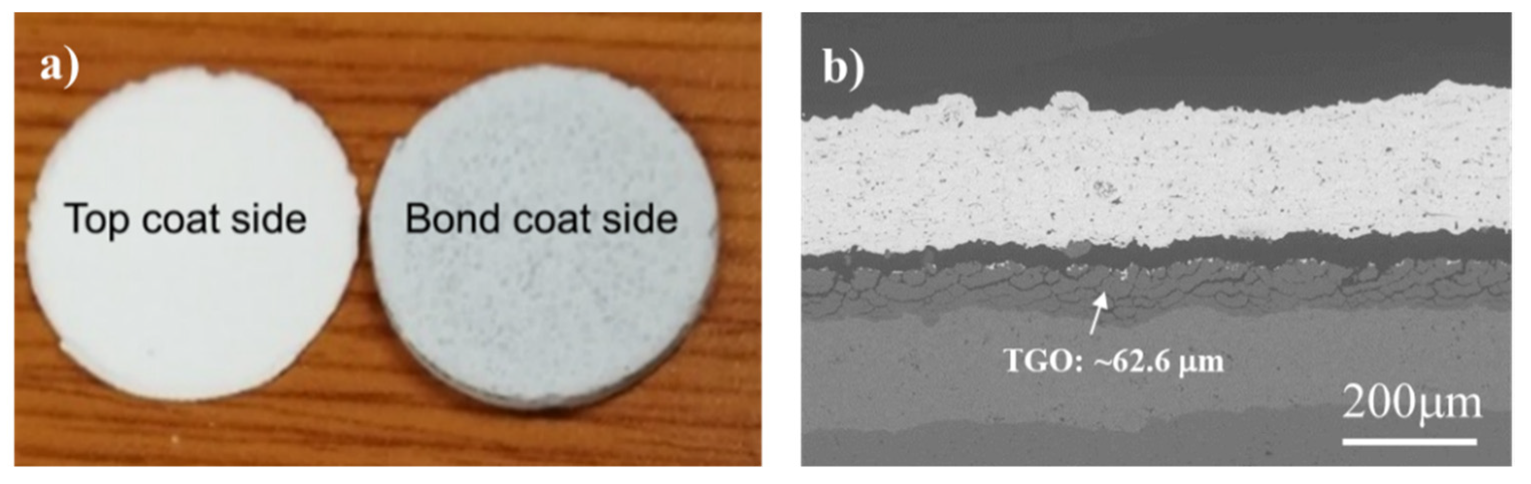
Figure 5). A typically failed APS EBC coating after 600 cycles in steam was shown in
Figure 6. The coating was failed by delamination of the entire ceramic top coat (as a one piece) from the substrate, and the failure occurred at the top coat/TGO interface. In SEM characterization, a fish-scale-like cracking TGO layer with a thickness of ≈63 µm is observed in the APS EBCs after 600 steam cycles (arrow indicated in the
Figure 6b). Compared to the TGO thickness in air atmosphere (
Figure 4a), it is obvious that the TGO layer of APS EBCs in steam is much thicker than that in air with a similar exposure duration at 1316 °C. The results indicated that TGO growth for APS EBC is accelerated under the steam cycling conditions. It has been demonstrated that water vapor is the primary oxidant for Si oxidation in a steam environment [
6]. Deal and Grove [
15] have shown that the oxidation rate of silicon was much higher in H
2O vapor than in dry O
2. Therefore, the accelerated TGO growth of a Si bond coat was expected in steam cycling for the APS EBCs. The rapid TGO growth and failure of APS EBCs in a steam environment compared to what was observed in air atmosphere clearly indicated that the thermal cycling of EBCs in air could result in false positive results.
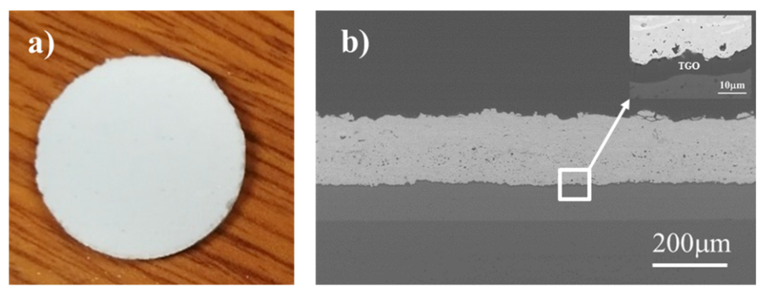
In contrast, the LPPS coatings remained adherent after 1000 cycles test in steam, and the SEM cross-section shows a good bonding between the top coat and bond coat (
Figure 7). Only a thin TGO layer was formed (insert in
Figure 7b). This points to the fact that LPPS EBCs have superior durability over APS EBCs in steam cycling.
3.5. TGO Growth Rate of APS and LPPS EBCs in Steam
The coating cross-section microstructures after various cycles at 1316 °C in 90% H
2O (g) + 10% air for APS and LPPS EBCs are shown in
Figure 8 and
Figure 9, respectively. A fish-scale-like cracking TGO layer is observed even after only 200 cycles in APS EBCs (
Figure 8a,b). Microcracks/gaps between TGO and the top coat are also observed. These microcracks/gaps may be caused by thermal stress due to the coefficient of thermal expansion (CTE) mismatch between the top coat and TGO/Si bond coat during thermal cycling. The average TGO thickness is ≈20 µm after 200 cycles, and it grows to ≈41 µm after 400 cycles and reached ≈63 µm after 600 cycles at failure. A linear TGO growth trend with respect to the number of steam cycles is revealed. XRD analysis on surface of the failed sample indicated that the fish-scale-like TGO layer was mostly composed of an α cristobalite phase. Richards et al. also confirmed the SiO
2 TGO as α-cristobalite phase via Raman analysis in a steam cycling test of plasma-sprayed Si/Yb
2Si
2O
7 EBC [
4]. It has been established that the oxide growth involves the formation of a thermodynamically stable β-cristobalite (SiO
2) structure at high temperature, and as the test conditions change to a cooling step, a phase transformation (from β-to-α) of this phase occurs at around 220 °C, which is calculated to cause ≈4.9% volume change [
16]. This volume change introduces severe cracking in the TGO layer, as shown in
Figure 8, which provides a short diffusion path to the environmental oxidants such as oxygen and water vapor. The continuous exposure of the coating to the test conditions (high temperature and steam) enables further interaction of the Si bond coat and the oxidants, causing an accelerated oxidation of the bond coat. The successive cycling of the EBCs continues to introduce further cracking and leads to an eventual failure.
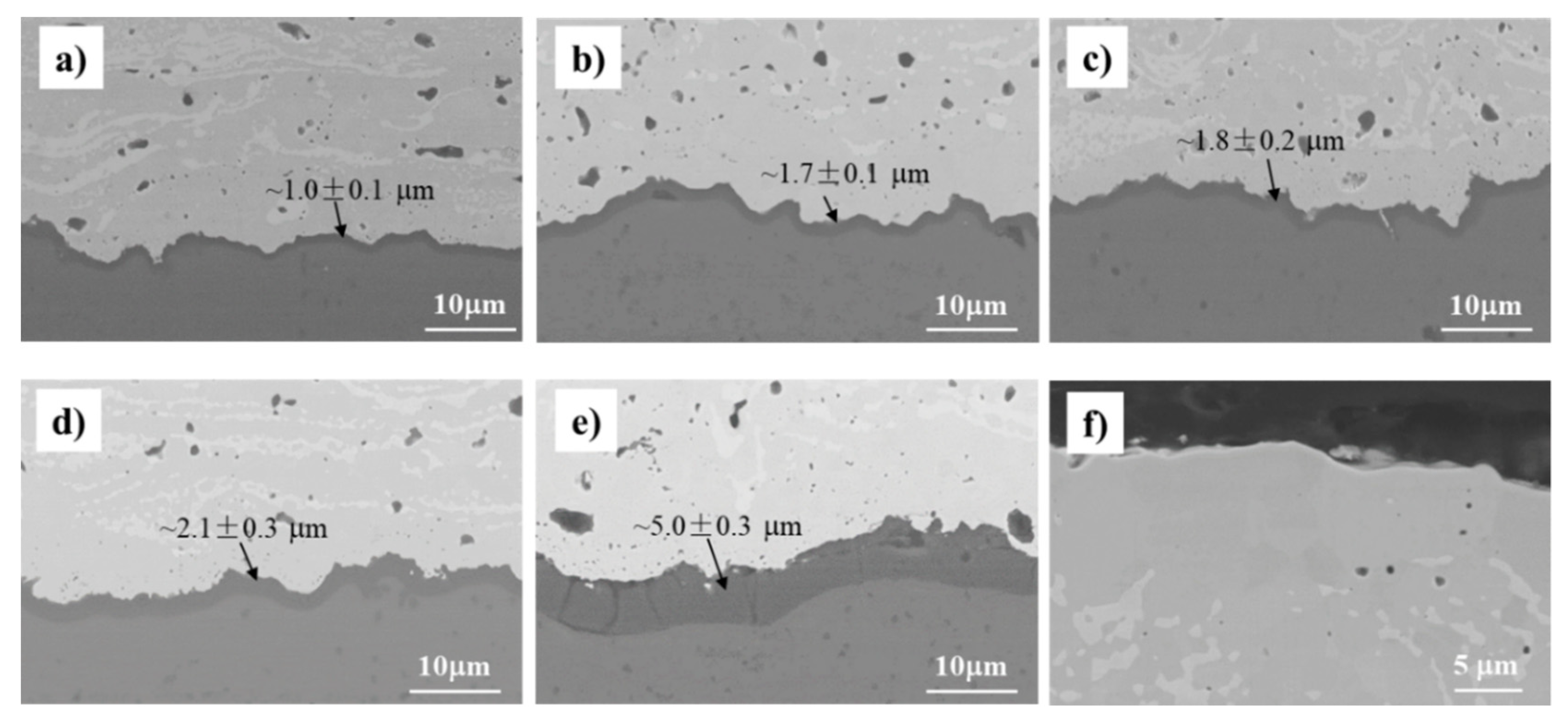
For LPPS EBCs, a thin and dense SiO
2 TGO layer is observed for all samples at various numbers of cycles (
Figure 9). The average TGO thickness is ≈1.0 µm (against ≈20 µm for APS EBC) after 200 cycles, and it gradually grows to ≈2.1 µm after 800 cycles and then starts to grow rapidly to ≈5.0 µm at 1000 cycles. Vertical cracks through the full TGO thickness are observed in the sample after 1000 cycles but are not shown in other samples. The cracking of the TGO as its thickness increased was attributed to the increased strain energy release rate when the TGO thickness exceeds a certain value (7). The accelerated TGO growth from 800 cycles to 1000 cycles can be attributed to the appearance of vertical cracks in the TGO, which provide a fast diffusion path for oxidants. The top coat microstructure after 1000 steam cycles is shown in
Figure 9f. No recession is observed on the coating surface, indicating the excellent steam recession resistance of the LPPS EBCs.
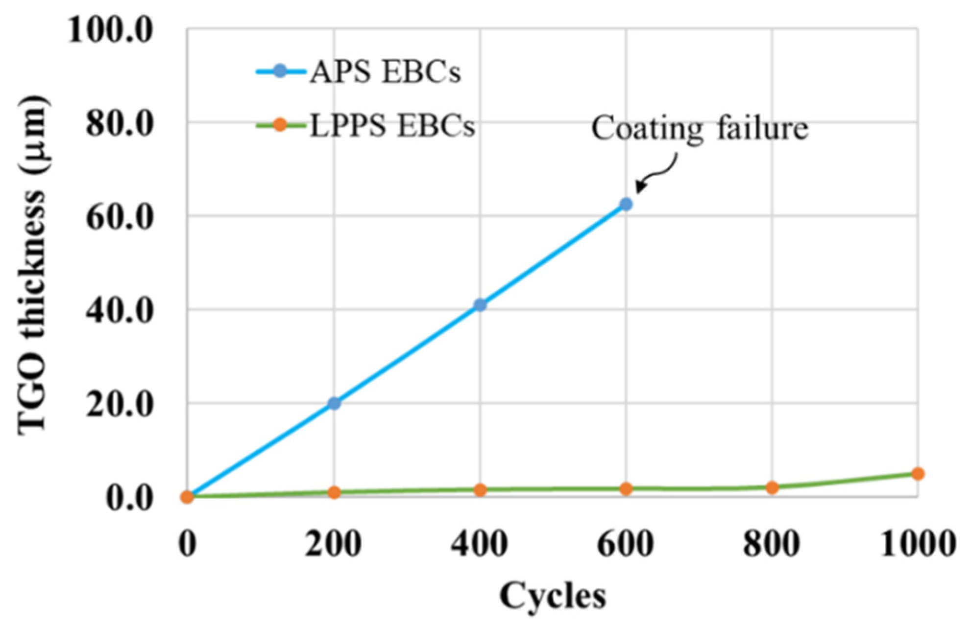
TGO thickness as a function of cycles for APS and LPPS EBCs at 1316 °C in 90% H
2O-10% air is plotted in
Figure 10. The TGO growth rate in APS EBCs is over 20 times higher than that in LPPS EBCs. Possible reasons for the fast TGO growth rate in the present APS EBCs will be discussed in
Section 3.6.
3.6. Failure Mechanism
The failure mechanism of various EBCs systems in a steam environment had been investigated. Kimmel et al. [
10] evaluated the BSAS/mullite + BSAS/Si EBC on SiC/SiC combustion liners in a gas turbine engine. The TGO layer with ≈60–100 µm thickness was formed in the inner liner after the 13,937 h field test at ≈1200 °C. Localized EBCs spallation was observed in the area with a TGO thickness over ≈200 µm. The thick TGO layer raised the middle and top layers, thus causing the EBCs coating to buckle/delamination. Richards et al. [
4] examined the thermal cycling properties of APS Yb
2SiO
5/mullite/Si tri-layer EBCs on a SiC substrate at 1316 °C in 90% H
2O–10% O
2. It was found that partial delamination occurred with the fracture plane located within a thermally grown oxide (TGO) at the mullite/Si interface. The formation of a cristobalite TGO was a major contributing factor to the poor steam cycling durability of this tri-layer EBC system. Richards et al. [
7] studied thermal cycling of APS Yb
2Si
2O
7/Si EBCs in water vapor and found that the delamination cracking initiated from the EBCs sample edge where the TGO was first formed due to the direct exposure of the Si bond coat to water vapor. A laboratory steam oxidation test by Lee [
6] also showed that the EBCs failed at TGO when TGO reaches a critical thickness. A common feature of the above-mentioned engine and laboratory rig tests indicated that the formation of TGO played a major role for the failure of EBCs.
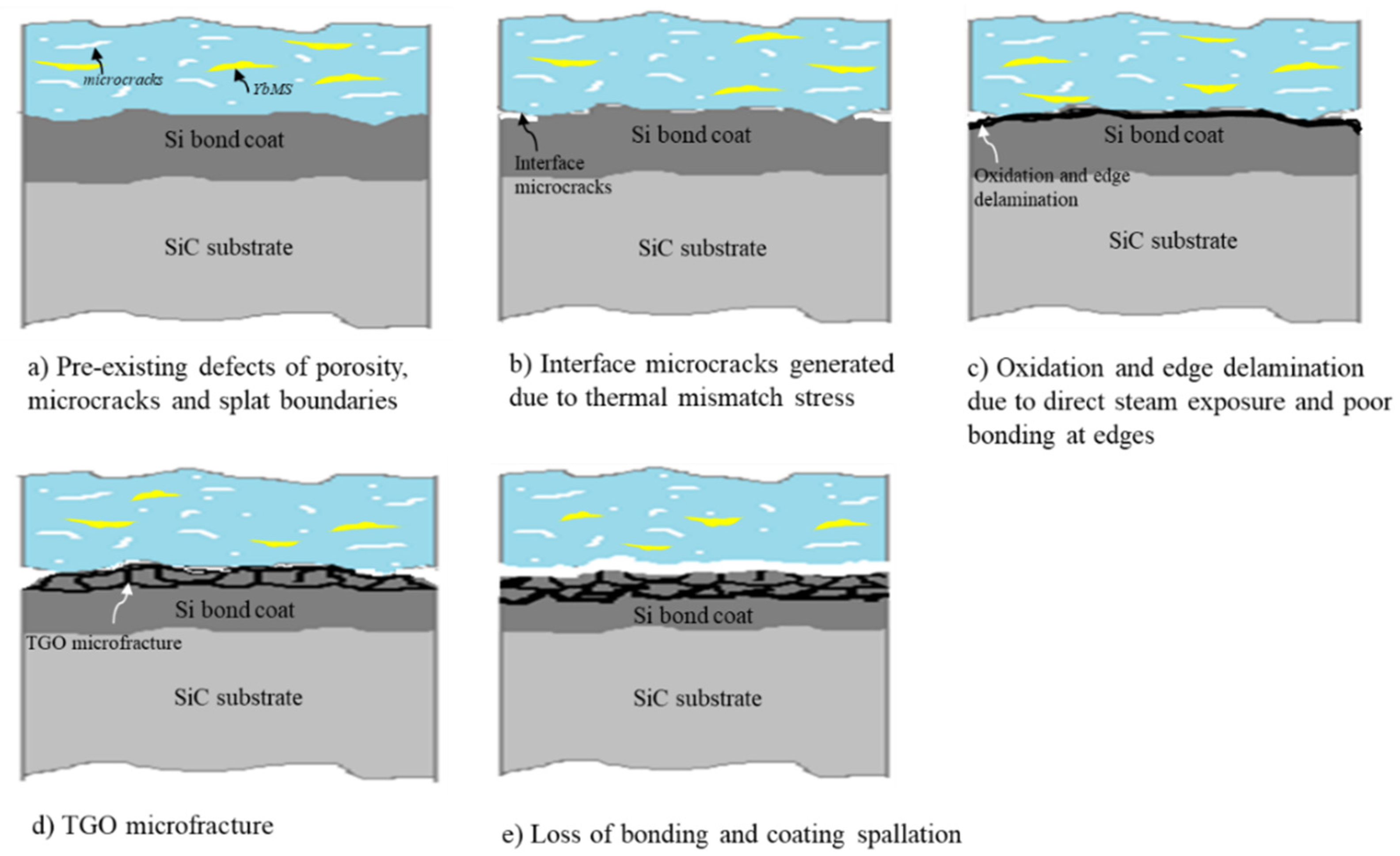
In the present study, a much shorter life and faster TGO growth had been observed in APS EBCs compared to the LPPS EBCs under the same steam cycling condition. The major driving forces for TGO growth and resultant short life in APS EBCs could be attributed to the following factors. The corresponding coating damage evolutions are schematically shown in
Figure 11.
From the above analysis, it can be concluded that in order to improve EBCs’ durability, it is critical to reduce the TGO growth rate by the deposition of dense and crack-free coatings with high bonding strength and reduced CTE mismatch (less Yb
2SiO
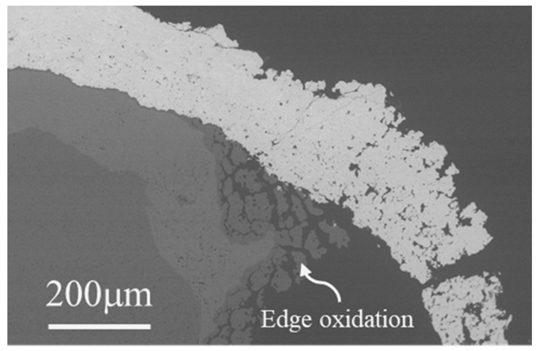
5 phase). The highly durable LPPS EBCs with a slow TGO growth rate further supports this viewpoint. It is interesting to note that severe coating edge oxidation/damage in the LPPS EBCs after 1000 cycles was also observed (
Figure 13). However, the damage by water vapor/oxygen attack is only limited to the coating edges. Unlike the thermal cycling behavior in APS EBCs, the severe oxidation/damage from the edge did not propagate toward the coating center. This remarkable difference is probably due to the high bond strength and close CTE match of the LPPS Yb
2Si
2O
7 coating with substrate. LPPS Yb
2Si
2O
7/Si EBCs showed promising application for SiC protection in a water vapor environment.
It is worth mentioning that the current state-of-the-art EBC systems with silicon as the bond coat are limited to the application/testing temperature of ≈1316 °C due to the low melting temperature of silicon (Tm = 1410 °C). For next-generation EBC-CMC, the temperature of the EBC-CMC interface is expected to exceed the melting point of Si; therefore, new bond coat materials are needed. Our current work demonstrated that the LPPS process has the capability for the deposition of highly durably dense EBCs due to the high particle temperature and velocity, which would be the preferred process for the deposition of next-generation EBCs with an advanced bond coat.
4. Conclusions
Yb2Si2O7/Si bilayer environmental barrier coatings (EBCs) were produced by air plasma spray (APS) and low-pressure plasma spray (LPPS) processes. LPPS EBCs showed denser and crack-free microstructures and higher bonding strength than APS EBCs. Thermal cycling behaviors were tested in air and in steam atmosphere at 1316 °C for both APS and LPPS EBCs. There is no coating failure in air atmosphere for both APS and LPPS EBCs after 900 cycles. In contrast, APS EBCs have an average life of 576 cycles in a steam cycling test in 90% H2O + 10% air at 1316 °C while LPPS EBCs survived 1000 cycles without failure. Failure of the APS EBCs occurred at the interface between the TGO and top coat. The TGO growth rate is the major driving force for EBCs failure. It was found that the TGO growth rate in APS EBCs is over 20 times higher than that in LPPS EBCs. The LPPS process is more promising than the APS process for producing highly durable EBCs with a far slower TGO growth rate.
Author Contributions
D.C.: Conceptualization, methodology, investigation, formal analysis, writing—original draft preparation; A.P.: methodology, investigation; G.D.: writing—review and editing; D.D.W.: funding acquisition; writing—review and editing; M.D.: writing—review and editing. All authors have read and agreed to the published version of the manuscript.
Funding
This research received no external funding.
Institutional Review Board Statement
Not applicable.
Informed Consent Statement
Not applicable.
Data Availability Statement
The data presented in this study are available on reasonable request.
Conflicts of Interest
The authors declare no conflict of interest.
References
- Padture, N.P. Advanced structural ceramics in aerospace propulsion. Nat. Mater. 2016, 15, 804–809. [Google Scholar] [CrossRef]
- Spitsberg, I.; Steibel, J. Thermal and environmental barrier coatings for SiC/SiC CMCs in aircraft engine applications. Int. J. Appl. Ceram. Technol. 2004, 1, 291–301. [Google Scholar] [CrossRef]
- Steibel, J. Ceramic matrix composites taking flight at GE aviation. Am. Ceram. Soc. Bull. 2019, 98, 32–36. [Google Scholar]
- Richards, B.T.; Begley, M.R.; Wadley, H.N. Mechanisms of ytterbium monosilicate/mullite/silicon coating failure during thermal cycling in water vapor. J. Am. Ceram. Soc. 2015, 98, 4066–4075. [Google Scholar] [CrossRef]
- Lee, K.N.; Fox, D.S.; Bansal, N.P. Rare earth silicate environmental barrier coatings for SiC/SiC composites and Si3N4 ceramics. J. Eur. Ceram. Soc. 2005, 25, 1705–1715. [Google Scholar] [CrossRef]
- Lee, K.N. Yb2Si2O7 Environmental barrier coatings with reduced bond coat oxidation rates via chemical modifications for long life. J. Am. Ceram. Soc. 2019, 102, 1507–1521. [Google Scholar] [CrossRef]
- Richards, B.T.; Young, K.A.; de Francqueville, F.; Sehr, S.; Begley, M.R.; Wadley, H.N. Response of ytterbium disilicate-silicon environmental barrier coatings to thermal cycling in water vapor. Acta Mater. 2016, 106, 1–14. [Google Scholar] [CrossRef] [Green Version]
- Bakan, E.; Marcano, D.; Zhou, D.; Sohn, Y.J.; Mauer, G.; Vaßen, R. Yb2Si2O7 environmental barrier coatings deposited by various thermal spray techniques: A preliminary comparative study. J. Therm. Spray Technol. 2017, 26, 1011–1024. [Google Scholar] [CrossRef]
- Richards, B.T.; Zhao, H.; Wadley, H.N.G. Structure, composition, and defect control during plasma spray deposition of ytterbium silicate coatings. J. Mater. Sci. 2015, 50, 7939–7957. [Google Scholar] [CrossRef]
- Kimmel, J.; Miriyala, N.; Price, J.; More, K.; Tortorelli, P.; Eaton, H.; Linsey, G.; Sun, E. Evaluation of CFCC liners with EBC after field testing in a gas turbine. J. Eur. Ceram. Soc. 2002, 22, 2769–2775. [Google Scholar] [CrossRef]
- Chen, D.; Pegler, A.; Dorfman, M. Environmental barrier coatings using low pressure plasma spray process. J. Am. Ceram. Soc. 2020, 103, 4840–4845. [Google Scholar] [CrossRef]
- Ueno, S.; Ohji, T.; Lin, H.T. Recession behavior of Yb2Si2O7 phase under high speed steam jet at high temperatures. Corros. Sci. 2008, 50, 178–182. [Google Scholar] [CrossRef]
- Refke, A.; Barbezat, G.; Dorier, J.L.; Gindrat, M.; Hollenstein, C. Characterization of LPPS processes under various spray conditions for potential applications. In Proceedings of the International Thermal Spray Conference, Orlando, FL, USA, 5–8 May 2003; pp. 1–8. [Google Scholar]
- Sampath, S.; Jiang, X.; Matejicek, J.; Leger, A.; Vardelle, A. Substrate temperature effects on splat formation, microstructure development and properties of plasma sprayed coatings Part I: Case study for partially stabilized zirconia. Mater. Sci. Eng. A 1999, 272, 181–188. [Google Scholar] [CrossRef]
- Deal, B.E.; Grove, A.S. General relationship for the thermal oxidation of silicon. J. Appl. Phys. 1965, 36, 3770–3778. [Google Scholar] [CrossRef] [Green Version]
- Breneman, R.C.; Halloran, J.W.; Arbor, A. Hysteresis upon repeated cycling through the beta-alpha cristobalite transformation. J. Ceram. Sci. Technol. 2015, 6, 55–62. [Google Scholar]
Figure 1.
Typical annealed coating microstructures at low and high magnifications. (a,b) APS Yb2Si2O7 coating; (c,d) LPPS Yb2Si2O7 coating.
Figure 1.
Typical annealed coating microstructures at low and high magnifications. (a,b) APS Yb2Si2O7 coating; (c,d) LPPS Yb2Si2O7 coating.
Figure 2.
XRD patterns of APS and LPPS coatings. (a) As-sprayed APS coating; (b) 1300 °C/10 h heat treated APS coating; (c) as-sprayed LPPS coating; (d) 1300 °C/10 h heat treated LPPS coating.
Figure 2.
XRD patterns of APS and LPPS coatings. (a) As-sprayed APS coating; (b) 1300 °C/10 h heat treated APS coating; (c) as-sprayed LPPS coating; (d) 1300 °C/10 h heat treated LPPS coating.
Figure 3.
Cross-section microstructures after bonding strength test for (a) APS and (b) LPPS Yb2Si2O7/Si EBCs.
Figure 3.
Cross-section microstructures after bonding strength test for (a) APS and (b) LPPS Yb2Si2O7/Si EBCs.
Figure 4.
Coating microstructures after 900 FCT cycle tests in air. (a) APS EBCs; (b) LPPS EBCs.
Figure 4.
Coating microstructures after 900 FCT cycle tests in air. (a) APS EBCs; (b) LPPS EBCs.
Figure 5.
Thermal cycling life of APS and LPPS EBCs in steam environment at 1316 °C. APS EBCs have an average life of 576 ± 65 cycles, while LPPS EBCs survived 1000 cycles without failure.
Figure 5.
Thermal cycling life of APS and LPPS EBCs in steam environment at 1316 °C. APS EBCs have an average life of 576 ± 65 cycles, while LPPS EBCs survived 1000 cycles without failure.
Figure 6.
Photograph (a) and SEM image (b) of failed APS EBC after 600 steam cycling.
Figure 6.
Photograph (a) and SEM image (b) of failed APS EBC after 600 steam cycling.
Figure 7.
Photograph (a) and SEM image (b) of LPPS EBC after 1000 steam cycles (insert showing the high magnification of the TGO layer).
Figure 7.
Photograph (a) and SEM image (b) of LPPS EBC after 1000 steam cycles (insert showing the high magnification of the TGO layer).
Figure 8.
SEM images of APS EBCs in steam cycling showing the TGO growth. (a,b) 200 cycles; (c) 400 cycles; (d) 600 cycles.
Figure 8.
SEM images of APS EBCs in steam cycling showing the TGO growth. (a,b) 200 cycles; (c) 400 cycles; (d) 600 cycles.
Figure 9.
Microstructures of LPPS EBCs for various steam cycles. (a) 200 cycles; (b) 400 cycles; (c) 600 cycles; (d) 800 cycles; (e) 1000 cycles; (f) Top coat cross-section microstructure after 1000 cycles at 1316 °C in 90% H2O (g) + 10% air.
Figure 9.
Microstructures of LPPS EBCs for various steam cycles. (a) 200 cycles; (b) 400 cycles; (c) 600 cycles; (d) 800 cycles; (e) 1000 cycles; (f) Top coat cross-section microstructure after 1000 cycles at 1316 °C in 90% H2O (g) + 10% air.
Figure 10.
TGO thickness as a function of cycles for APS and LPPS EBCs at 1316 °C in 90% H2O-10% air.
Figure 10.
TGO thickness as a function of cycles for APS and LPPS EBCs at 1316 °C in 90% H2O-10% air.
Figure 11.
Schematic of damage evolution of APS EBCs in a steam cycling test. (a) Pre-existing defects of porosity, microcracks and plant boundaries, (b) Interface microcracks generated due to thermal mismatch stress, (c) Oxidation and edge delamination due to direct steam exposure and poor bonding at edges, (d) TGO microfracture, (e) Loss of bonding and coating spallation.
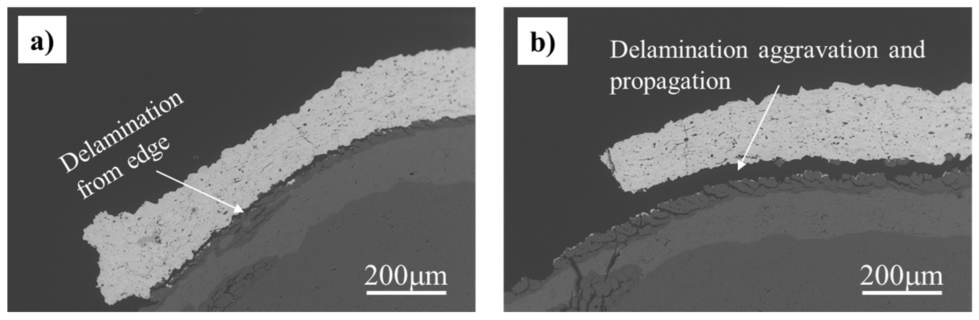
Figure 12.
SEM images of APS EBCs coating edges after steam cycling. (a) 200 cycles; (b) 400 cycles.
Figure 12.
SEM images of APS EBCs coating edges after steam cycling. (a) 200 cycles; (b) 400 cycles.
Figure 13.
SEM image of LPPS EBCs coating edge after 1000 steam cycles.
Figure 13.
SEM image of LPPS EBCs coating edge after 1000 steam cycles.
| Publisher’s Note: MDPI stays neutral with regard to jurisdictional claims in published maps and institutional affiliations. |
© 2021 by the authors. Licensee MDPI, Basel, Switzerland. This article is an open access article distributed under the terms and conditions of the Creative Commons Attribution (CC BY) license (https://creativecommons.org/licenses/by/4.0/).


