
Modeling and Simulation of Vacuum Low Pressure Carburizing Process in Gear Steel


1
National Local Joint Engineering Laboratory of Intelligent Manufacturing Oriented Automobile Die& Mold, Tianjin University of Technology and Education, Tianjin 300222, China
2
Beijing Research Institute of Mechanical & Electrical Technology, Beijing 100083, China
3
Ningbo Haizhi Institute of Material Industry Innovation, Ningbo 315000, China
4
Saitama Institute of Technology, Fukaya 3690293, Japan
*
Author to whom correspondence should be addressed.
Coatings 2021, 11(8), 1003; https://0-doi-org.brum.beds.ac.uk/10.3390/coatings11081003
Submission received: 24 July 2021
/
Revised: 15 August 2021
/
Accepted: 19 August 2021
/
Published: 23 August 2021
(This article belongs to the Special Issue Surface Modification and Functionalization for Advanced Materials)
Abstract
:A combination of simulation and experimental approaches to optimize the vacuum carburizing process is necessary to replace the costly experimental trial-and-error method in time and resources. In order to accurately predict the microstructure evolution and mechanical properties of the vacuum carburizing process, a multi-field multi-scale coupled model considering the interaction of temperature, diffusion, phase transformation, and stress was established. Meanwhile, the improved model is combined with the heat treatment software COSMAP to realize the simulation of the low-pressure vacuum carburizing process. The low-pressure vacuum carburizing process of 20CrMo gear steel was simulated by COSMAP and compared with the experimental results to verify the model. The results indicated that the model could quantitatively obtain the carbon concentration distribution, Fe-C phase fraction, and hardness distribution. It can be found that the carbon content gradually decreased from the surface to the center. The surface carbon concentration is relatively high only after the carburizing stage. With the increase in diffusion time, the surface carbon concentration decreases, and the carburized layer depth increases. The simulated surface carbon concentration results and experimental results are in good agreement. However, there is an error between calculations and observations for the depth of the carburized layer. The error between simulation and experiment of the depth of carburized layer is less than 6%. The simulated surface hardness is 34 HV lower than the experimental surface hardness. The error of surface hardness is less than 5%, which indicates that the simulation results are reliable. Furthermore, vacuum carburizing processes with different diffusion times were simulated to achieve the carburizing target under specific requirements. The results demonstrated that the optimum process parameters are a carburizing time of 42 min and a diffusion time of 105 min. This provides reference and guidance for the development and optimization of the vacuum carburizing process.
1. Introduction
Gear is a key component of a mechanical transmission system. With the increasing requirements on transmission parameters, the surface hardness and wear resistance of gear teeth are also improved. Surface strengthening must be carried out to meet the performance requirements of gear that are tough at the core and hard on the surface [1]. Vacuum carburizing is an important heat treatment process for gear surface strengthening, which makes the gear surface have a specific carbon concentration and improves the surface hardness of the workpiece after quenching treatment. The ultimate goal is to improve the bearing capacity and service life of gears [2,3,4,5]. In recent years, vacuum carburizing as an environmentally friendly heat treatment process has received widespread attention. Due to carburizing in a vacuum, there is no oxidation at the grain boundary, improving microstructure and properties. Vacuum low-pressure carburizing technology has good surface quality, good uniformity of carburizing layer, small deformation, environmental pollution, and other characteristics [6]. Vacuum low-pressure carburizing can introduce small amounts of carburizing gas at a temperature within the range of 900–1050 °C. Due to the high temperature, the carbon transfer is more efficient in the case of the conventional carburizing method, thus leading to a shorter carburizing time [7]. Vacuum carburizing with good development prospects is a real environmentally friendly and green heat treatment technology. At present, vacuum carburization technology is replacing the traditional gas carburizing technology and is more and more widely used, especially in the automotive industry. Vacuum low-pressure carburizing is the frontier technology of current heat treatment development [8,9].
Low-pressure vacuum carburizing is a non-equilibrium carburizing process, which can be divided into a boost period and diffusion period [10]. The former is to maintain the carburizing medium hydrocarbon gas atmosphere to infiltrate carbon into the steel, and the latter is to make carbon diffuse into the steel in a vacuum. The use of acetylene as a source of carbon for carburizing eliminates the problems of soot and tar formation typical for other hydrocarbon atmospheres, provides high quality and surface finish, rapid saturation of the surface layers with carbon, lowering of the gas consumption, and shortening of the duration of the process [11]. The final distribution of carbon depends on the diffusion rate and process parameters of carbon in the steel, specifically the carburizing time, temperature, gas pressure, and flow rate. Therefore, it is difficult to accurately control the carbon concentration in experiments [12,13]. At present, the optimization method of vacuum carburizing is mainly based on time-consuming and difficult to control experiments. Traditional methods usually involve trial-and-error methods and empirical analysis, which are costly and rarely produce optimal solutions. Therefore, effective simulation tools are needed to accurately simulate the vacuum carburizing process and predict the carburizing performance. The simulation of different vacuum carburizing processes will improve the efficiency of the experiment and reduce the optimization cost of the vacuum carburizing experiment.
Numerical simulation of vacuum carburizing has many advantages in controlling and improving the carburizing process. Many scholars have conducted extensive research on vacuum carburizing simulation. They established different vacuum carburizing models to simulate the vacuum carburizing process. Kim et al. established a finite element model for vacuum carburizing considering both heat transfer and carbon diffusion. The change of gear temperature with time in the vacuum carburizing process was obtained by heat transfer analysis, and the carbon concentration was calculated. The microstructure of martensite in different parts of the gear ring can be well explained by the calculated carbon concentration [14]. Wei, Y et al. established gas carburizing and vacuum carburizing models. The carburization properties of steel after gas and vacuum carburization heat treatment were predicted by using the simulation tool CarbTool©. The predicted values are in good agreement with the experimental results. The proposed effective carburizing model not only predicts the carbon distribution but also optimizes the process between cycle time and total cost [15]. Kula et al. investigated the duration of the carburizing process and the effectiveness of carbon transfer in two-stage and multi-stage carburizing processes. The number and duration of the “boost”/”diffusion” stages of the vacuum carburizing process for 18CrNi8 steel were optimized. The results show that the total process time and carburizing efficiency depend on the value of the minimum instantaneous carbon concentration obtained on the steel surface during the diffusion stage [16]. Zajusz et al. established a model for carbon diffusion in pulsed carburizing multi-alloy based on the bi-velocity method. The numerical calculations are made for the pulse carburizing of 20 steel under different boost/diffusion cycles. The boost and diffusion stages of the vacuum carburizing process were optimized considering the trade-off between economic aspects and the functional properties of the carbon content and its distribution [17]. By studying the unique pulse carburizing method of vacuum carburizing, they used different software for modeling. It can be found that the effective vacuum carburizing model can realize the prediction of the vacuum carburizing process.
Tibbetts et al. reported that the carburizing layer thickness and carbon distribution after vacuum carburizing depend on process parameters and mass transport. The latter is described by two main parameters: the mass transfer coefficient β and the diffusion coefficient DC [18,19]. The diffusion coefficient and transfer coefficient are important parameters to control the low-pressure vacuum carburizing process. The choice of their mathematical models directly determines the accuracy of the numerical simulation of the low-pressure vacuum carburizing process [20,21,22]. Rokicki et al. formulated specific process methods based on different acetylene flow values. The effect of acetylene flow on the properties of the carburized layer was investigated. It was shown that acetylene flow is necessary for the control of diffusion and transfer coefficients. Acetylene flow is one of the most critical parameters affecting the uniformity of the carburized layer properties [23]. Semenov et al. determined the parametric expressions of the carbon potential and mass transfer coefficient in the low-pressure carburizing process based on experimental data on the formation of saturated carbon layers in vacuum carburizing. These expressions were used as boundary conditions in the model with cyclic carburizing. The accuracy of the developed mathematical model was confirmed by comparing the calculated results with the experimental results [24]. Jung et al. investigated the relationship between carbon diffusivity and numerical measurement methods for different contents of carbon and alloying elements in steel. A prediction model of carbon concentration distribution considering the influence of other alloying elements has been proposed. The carbon concentration distribution of the acetylene vacuum carburizing of SCM415 steel was calculated. A comparison of the measured and calculated values shows good agreement, which validated the prediction model [25,26,27,28]. Kaffenberger et al. discussed how the alloying elements in steel change the diffusion coefficient and distribution of carbon. A model based on alloy-related diffusion coefficient calculations was described. Carburizing experiments were performed to confirm the SimCarb diffusivity prediction. The results showed that the diffusion coefficient of carbon in austenite depends strongly on the steel composition. The diffusion coefficient not only considered the effect of temperature and carbon concentration but also the effect of alloying elements in the steel on the diffusion rate to improve the accuracy of the simulation calculation [29]. Current research mainly focused on the carbon diffusion process under different process conditions. There are few studies on the properties of the workpiece after carburizing. It is necessary to establish a complete model to simulate the whole process of low-pressure vacuum carburizing and high-pressure gas quenching.
The purpose of this paper is to accurately predict the carbon concentration distribution, microstructure transformation, and hardness of gear steel during vacuum carburizing by finite element numerical simulation. An improved multi-field multi-scale “temperature-diffusion-transformation-stress field” model was established and coupled with the heat treatment process simulation software COSMAP. The model is applied to simulate the vacuum carburizing process of 20CrMo steel, and the simulated results are discussed. The paper is organized as follows: the multi-field computational model and the hardness regression equation are described in Section 2, the experimental materials and methods are presented in Section 3, the simulation verification results and discussion are given in Section 4, and the conclusions are given in the last section.
2. Model Descriptions
In this paper, an improved temperature-diffusion-transformation-stress multi-field coupling theory is proposed, as shown in Figure 1 [30,31]. The multi-physical fields involved in the numerical simulation of vacuum low-pressure carburizing include temperature field, diffusion field, transformation field, and stress field. The interaction between the diffusion field and other physical fields can be summarized as follows:
- Temperature changes affect the diffusion rate of carbon atoms in austenite. Moreover, the diffusion process and subsequent phase transformation during the cooling process generate latent heat.
- With the increase in carbon concentration, the diffusion ability of carbon in austenite increases. In addition, the precipitation of alloy carbides can affect carbon diffusion during carburizing.
- The increase in the carbon concentration gradient in the carburized layer causes the appearance of diffusion stress. The non-uniform distribution of stress also affects the diffusion process of carbon atoms and the kinetic process of phase transformation, while the existence of an internal stress gradient affects the diffusion mechanism of carbon in steel.
2.1. Temperature Field Calculation
The low-pressure vacuum carburizing process involves complicated temperature changes such as heating, holding, and cooling. Therefore, the calculation of temperature field distribution needs to consider the influence factors such as specific heat and stress. The current study uses the following heat conduction equation:
where, is the density, is the specific heat, is the stress, is the elastic strain, is the enthalpy density, and is the thermal conductivity.
The following equation was used for the boundary condition of heat transfer.
where, is the heat transfer coefficient with temperature, T is the workpiece temperature, and is the medium temperature.
The thermo-physical parameters of 20CrMo steel used in this paper were calculated by JMatPro. Figure 2 shows the heat conduction, specific heat, and density as a function of temperature.
2.2. Diffusion Field Calculation
Vacuum carburizing can be divided into three processes:
- Carburizing medium for chemical decomposition;
- Carbon atoms were transferred into the surface of the steel part;
- Due to the existence of a potential carbon concentration gradient, carbon atoms diffuse into the steel.
The final carbon concentration distribution after vacuum carburizing depends on the carbon diffusion rate, carbon transfer coefficient, and vacuum carburizing process parameters (including carburizing time, carburizing temperature, gas pressure, and gas flow, etc.).
The carbon diffusion process follows Fick’s law, which can be determined by the following diffusion equation:
where, is the carbon diffusion coefficient varying with concentration. The value relates to carburizing temperature and alloy composition, which can be obtained from the following equation [32]
where, is the gas constant and its value is 8.314 J/mol/K, is the alloying element influence factor, which depends on the type and content of alloying elements.
In the process of low-pressure vacuum carburizing, the carbon content of the steel surface and the carburizing atmosphere do not reach an equilibrium, which depends on the absorption and chemical reaction process on the steel surface. Therefore, the carburizing boundary condition equation is as follows.
where, and are the carbon concentration and carburizing potential, is the surface carbon transfer coefficient, whose value is related to the carburizing temperature, gas reaction efficiency, and gas pressure.
2.3. Phase Transformation Calculation
Austenite transformation occurs in steel during the quenching and cooling process. Diffusion (semi-diffusion) phase transformation and non-diffusion phase transformation occur according to the different transformation temperatures and cooling rates. The main products of diffusion (semi-diffusion) phase transformation are pearlite and bainite. The current model of diffusion phase transformation fraction is calculated as the following equation:
where, T is the temperature, and is the stress.
The main product of non-diffusion phase transformation is martensite, as calculated by the following equation:
where, is the martensitic transformation start temperature and is the stress.
2.4. Hardness Regression Equation
The hardness of the workpiece after vacuum carburizing mainly depends on the phase structure of the steel, which can be calculated by the experimental regression equation [33].
where and represent the different Fe-C phase contents and weighting factors, while and represent the alloy compositions and their corresponding weighting factors.
2.5. Establishment of Multi-Field Multi-Scale Model for Low Pressure Vacuum Carburizing
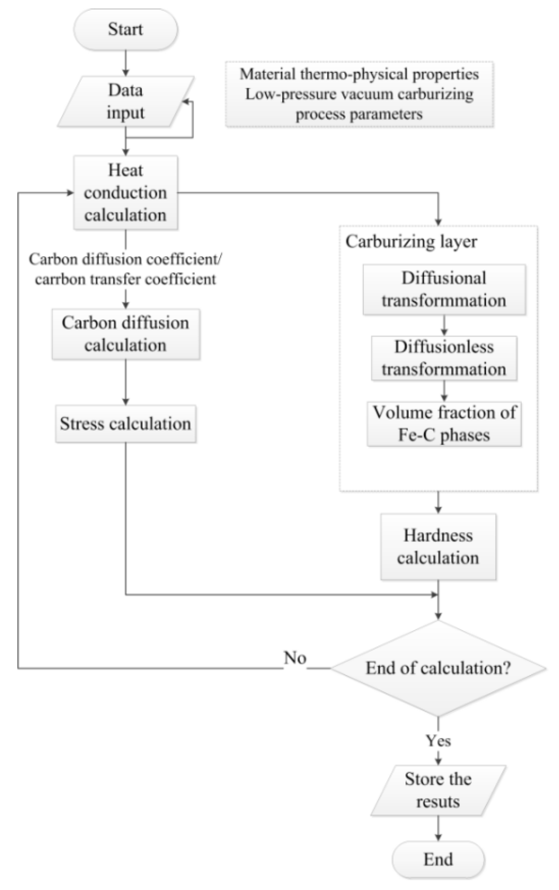
Based on the equations summarized in the previous section, a multi-field multi-scale model was established. Multi-field multi-scale model, as the name implies, includes multiple physical fields and multiple scales. The multi-physical fields include temperature field, diffusion field, transformation field, and stress field. The multi-scale of this model includes macro-scale and meso-scale. The data transfer and exchange between different physical fields and different scale models are performed according to the rules in Figure 3. The temperature field, diffusion field, and stress field are calculated by the macroscopic scale finite element method. The Fe-C phase fraction and hardness are obtained by mesoscopic scale transformation kinetic. The established multi-field multi-scale coupling model was integrated into the heat treatment finite element software COSMAP to simulate the vacuum carburizing process.
3. Material and Methods
3.1. Experimental Material
The low-pressure vacuum carburizing experiments were conducted in the WZD-40 low-pressure vacuum carburizing gas quenching multifunctional furnace of the Beijing Institute of Mechanical and Electrical Technology Co., Ltd. (Beijing, China). The material used in this study is a typical gear steel 20CrMo, prepared in the form of a cylindrical sample of Φ 15 mm × 100 mm. Table 1 shows the chemical composition of 20CrMo steel. Table 2 shows the mechanical properties of 20CrMo steel.
3.2. Experimental Methods
Vacuum carburizing heat treatment is actually through the “carburizing + diffusing” multistage pulse and a concentrated diffusion to achieve the corresponding carburizing requirements. The carburizing process was carried out through high-temperature and low-pressure pulse under vacuum conditions. Table 3 shows the process scheme of the vacuum carburizing experiment. The vacuum carburizing furnace was heated to 930 °C. The samples were transferred from the cold chamber to the hot chamber, preheated once at 600 °C, and kept for 30 min to ensure they are sufficiently heated. After preheating, the heated carburizing temperature was 930 °C for 30 min. After that, the samples were carburized. The carburizing medium was C2H2 gas introduced with a flow rate of 8 L/min and carburizing pressure of 3 kPa. Finally, gas quenching was performed directly after carburizing at a pressure of 6 bar.
The experiments were carried out by the multi-stage pulse method of “carburizing + diffusion,” and Figure 4 shows the illustration of the vacuum pulse carburizing stage. The carburizing period consists of several low-pressure pulses. Each pulse includes charging, pressure-holding, and pumping processes. In the vacuum atmosphere, carburizing gas (acetylene gas + nitrogen) was introduced as soon as the temperature rose and uniform heating of each part was finished. The specified carburizing pressure is reached in the furnace after 90 s, and all parts of the workpiece surface will be evenly located in the carburizing atmosphere. After the specified carburizing time, the gas in the furnace was pumped out. The single pulse cycle is 210 s, and the cycle was repeated 12 times.
The sample was cut after vacuum carburizing. One part was used for carbon content detection. The carbon content was measured by the infrared absorption method. The other part was used for hardness and microstructure detection. The samples were ground, and the hardness tests (0.2 kg) were completed on a Micro Vickers hardness tester (INNOVATEST 423D, Maastricht, Netherlands). The samples were corroded in 4% nitric acid alcohol, and the microstructures were examined on the optical microscope (Zeiss Axio scope. A1, Jena, Germany).
4. Results and Discussion
A finite element model was built by the GID software to simulate the vacuum carburizing process. Because the geometry of the sample and the boundary condition of carburizing are axisymmetric, a two-dimensional model was established. The sample length was L = 100 mm, and diameter D = 15 mm. The number of nodes was 1071, and the number of meshes was 1000. The finite element mesh of the sample is shown in Figure 5. The carburization process only occurs within a few millimeters of the surface of the part. The simulation needs to focus on the change of carbon concentration on the surface. In order to ensure the accuracy of the calculation results and reduce the numerical oscillation, local mesh refinement was performed for the surface. In order to save calculation time, the finite element mesh is slightly larger for the internal where the carburization process has not occurred.
4.1. Carbon Concentration Analysis
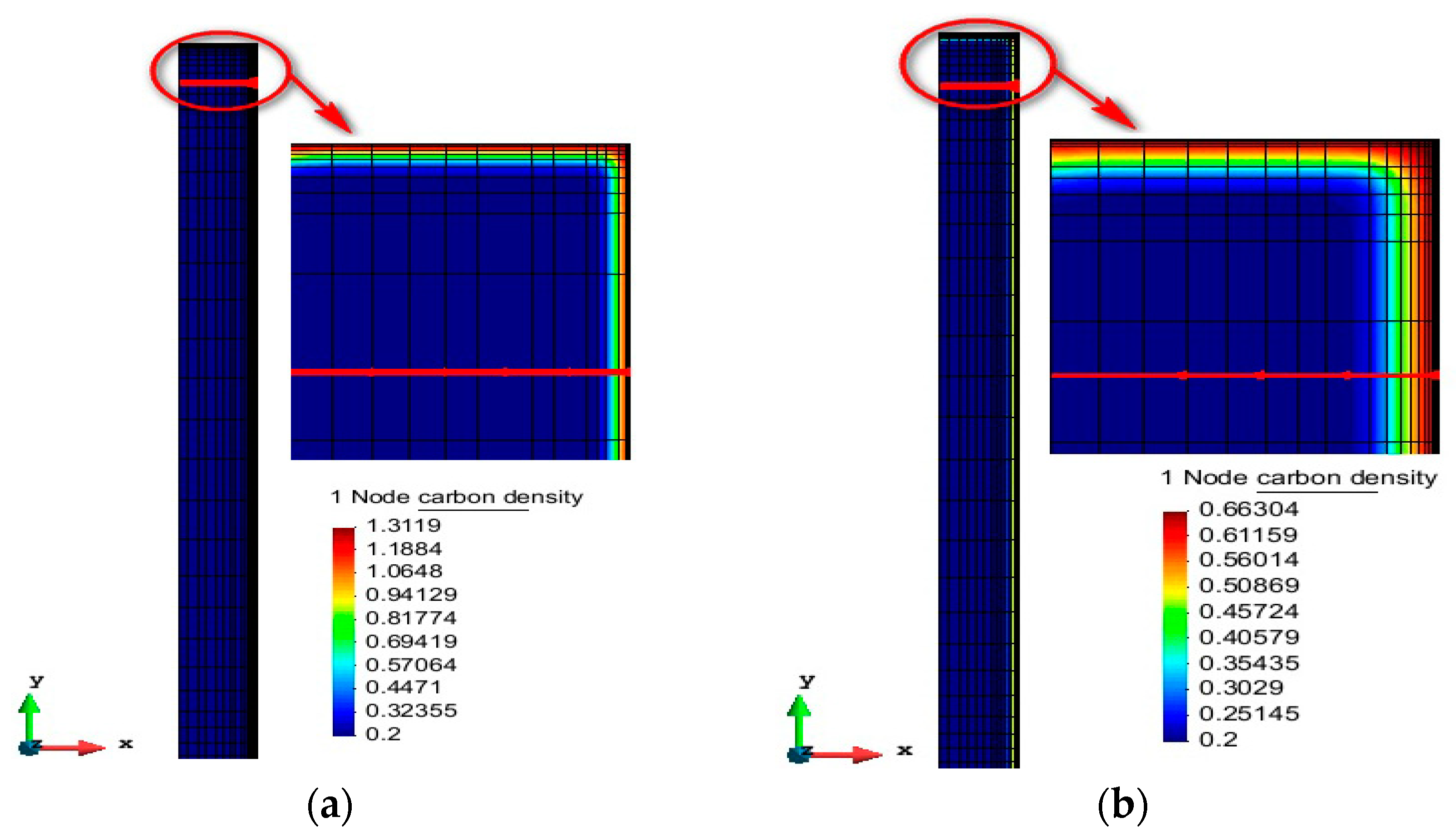
Figure 6 shows the carbon concentration distribution of 20CrMo steel under different vacuum carburizing conditions. Carbon concentration decreases with increasing distance from the surface to the center. The surface carbon content of process 1 is 1.31%, and process 2 is 0.66%. Because process 1 only carries out carburizing (42 min), carbon atoms on the surface of the workpiece are continuously enriched during the carburizing stage. Active carbon atoms gather on the surface, resulting in high surface carbon concentration. It can be seen that the carburized layer is shallow, and the surface carbon concentration is high in the carburizing stage. With the progress of diffusion, the depth of carburized layer increases, and the surface carbon concentration decreases significantly. The reason for this phenomenon is that in the process of vacuum carburizing, carbon is continuously transported to the sample surface, which increases the surface carbon concentration. However, the internal carbon concentration remains constant, creating a carbon concentration gradient from the surface to the inside. With the increase in diffusion time, carbon diffused from the surface to the interior, and the surface carbon concentration decreased.
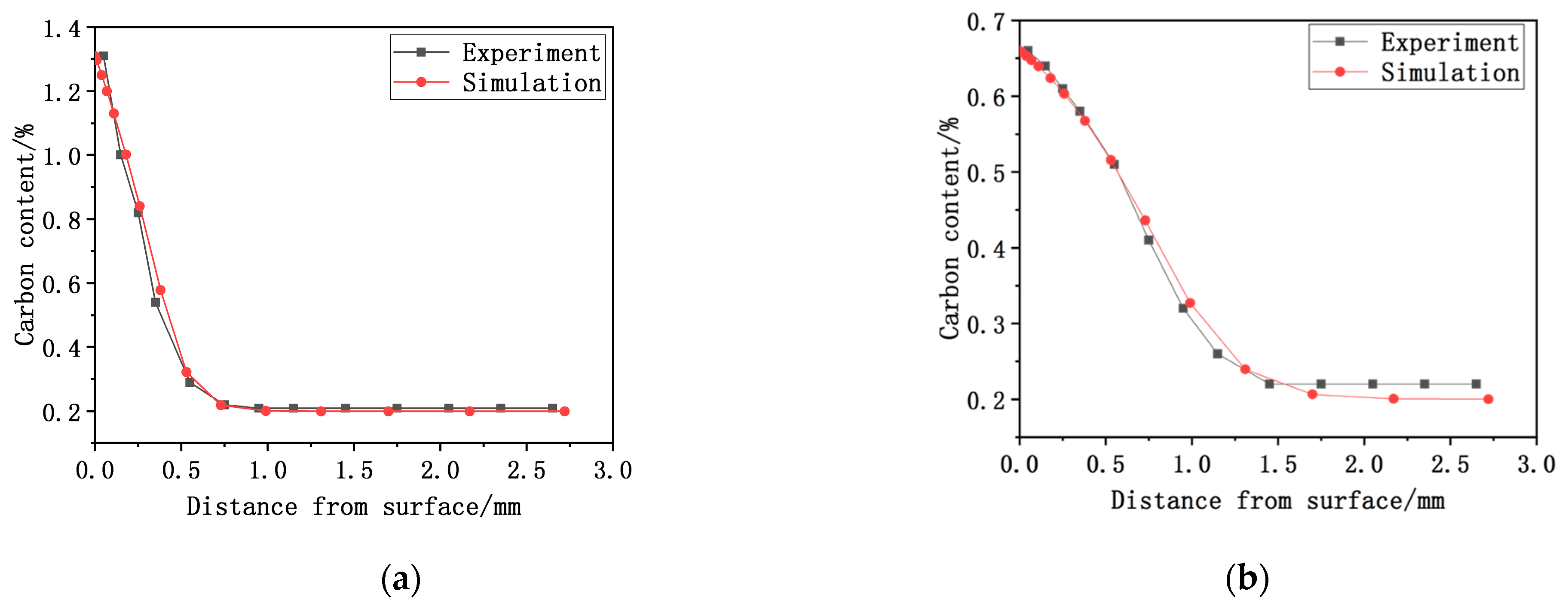
The carbon concentration distribution curves were obtained by taking the value of carbon concentration along the depth direction at the position shown by the red arrow (Figure 6). Figure 7 shows the comparison of carbon content distribution from surface to interior between simulation and experiment after vacuum carburizing. It can be seen that the simulated carbon concentration distribution results and experimental results are in good agreement, which verifies the accuracy of COSMAP numerical simulation. The surface carbon concentration of process 1 is 1.31%, and that of process 2 is 0.66%. Experiment and simulation of carburizing depth process 1 are basically consistent. In process 2, the depth of the experimental carburized layer is 0.883 mm, and the depth of the simulated carburized layer is 0.935 mm. The error between the simulation and experiment of the depth of the carburized layer is 5.88%, and the initial suppose is achieved. The reason for the error in carbon concentration distribution may be related to the diffusion coefficient. The diffusion coefficient of the simulation calculation is considered such that the alloy composition and temperature of the sample are uniform. However, the alloy composition and temperature of the actual vacuum carburizing sample may be uneven.
4.2. Microstructure and Hardness Analysis
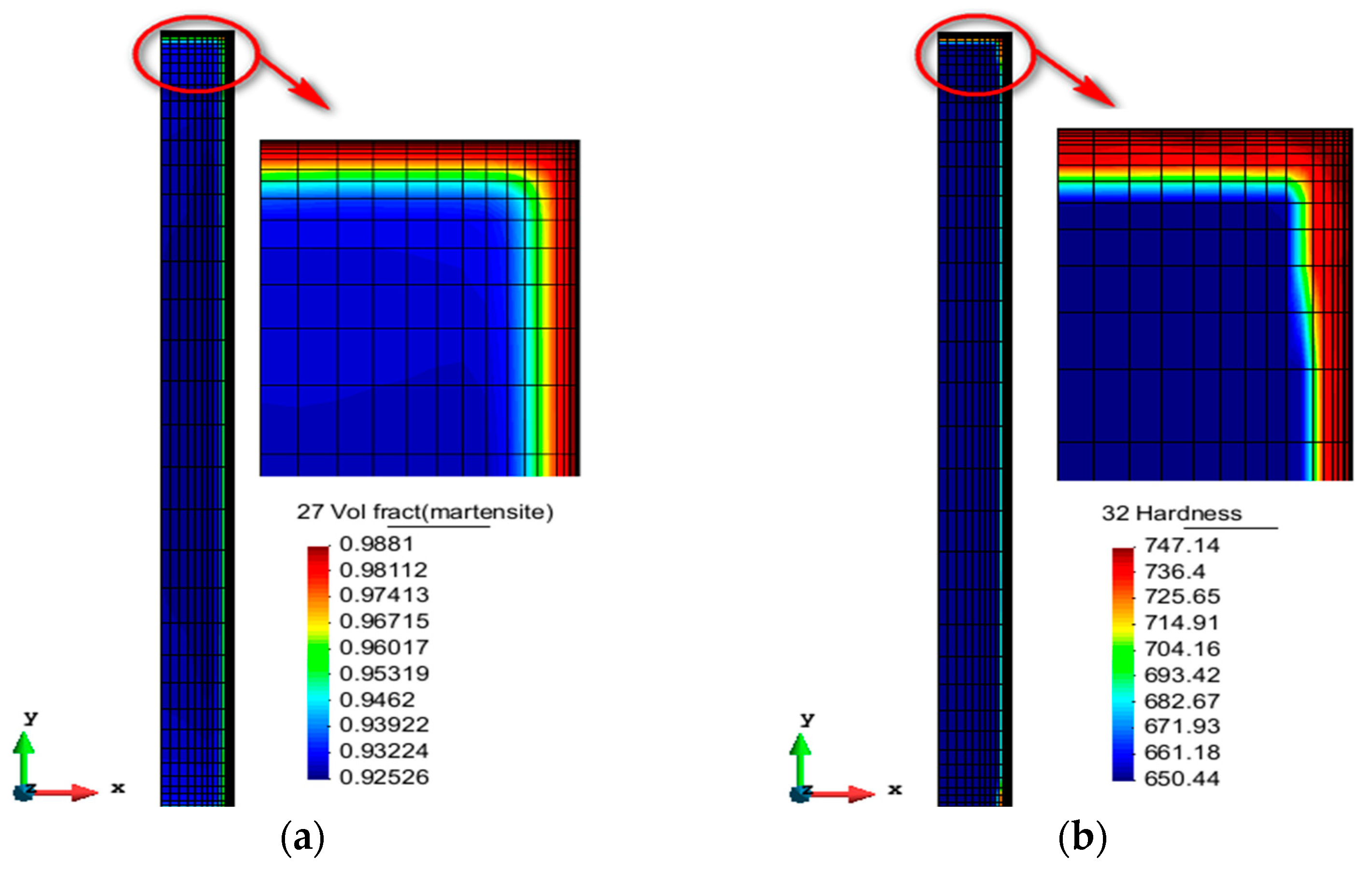
Figure 8 shows the simulated distribution of martensite and hardness after quenching in the vacuum carburizing process 2. After vacuum carburizing, the martensite on the surface is evenly distributed, with a highest martensite content of 97.5%. The martensite content gradually decreased from the surface to the center. This is confirmed by the SEM microstructure results (Figure 9). After vacuum carburizing in process 2, high-hardness martensite is observed in the deep layer within 400 μm, and the hardness of martensite reached its peak. With an increase in the carburized layer depth, the martensite structure decreases, and the hardness decreases rapidly. The simulation results are consistent with the experimental results and the vacuum carburizing theory.
Figure 10 shows the temperature changes of the inner and outer surfaces. Point B is near the outer surface, where the cooling rate is faster. However, point A, which relies on internal heat conduction, is close to the internal surface, and the cooling rate is slow. The martensite content varies with the cooling rate. The surface cooling rate is relatively high during quenching, and the transformation from austenite to martensite occurs rapidly. The cooling rate from the surface to the center gradually decreases, and the amount of transformation from austenite to martensite decreases, so the martensite content from the surface to the center gradually decreases. In general, the hardness value of quenched gear steel depends on the martensite content, so the distribution of hardness value is the same as that of martensite volume fraction.
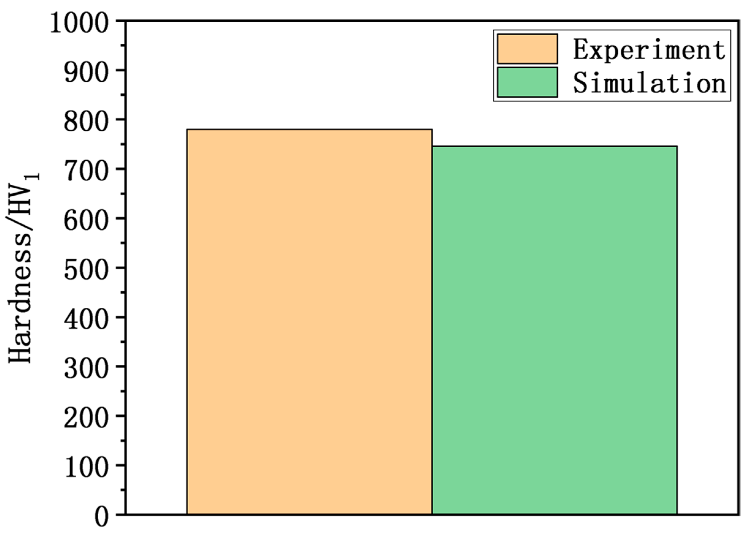
Figure 11 shows a comparison of the surface hardness between simulation and experiment of process 2 (42 min + 140 min). The surface hardness value of the experiment is 780 HV. The simulated surface hardness is 746 HV, which is slightly lower than the experimental value. The surface hardness error is within 5%, so the simulation results showed a higher credibility. The problem probably lies in the measurement of the experimental hardness, as it is in a small area, while the simulated hardness calculation is mainly carried out for the average value of the simulated domain.
4.3. Optimization Analysis
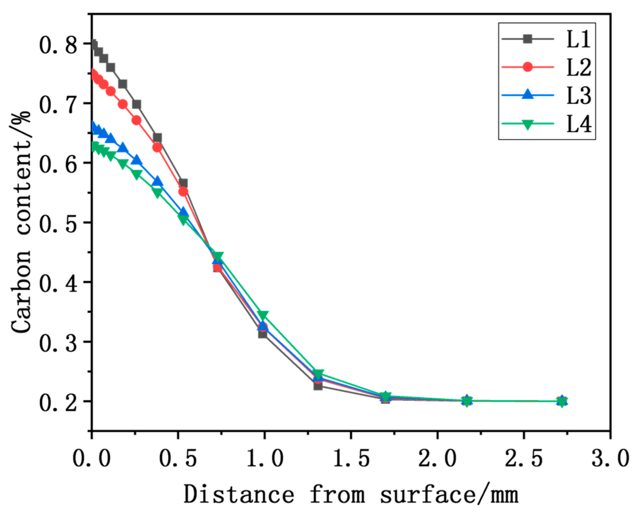
A surface carbon concentration of 0.80% and a carburizing layer depth of 0.90 mm was taken as the carburizing target. Simulations were performed for 20CrMo steel under vacuum carburizing conditions with the same carburizing time (42 min) and different diffusion times (105 min, 125 min, 145 min and 165 min). The selection of other process parameters is the same as the above experiment. Figure 12 shows the results of carbon content distribution at different diffusion times simulated by COSMAP. From Figure 12, we can see that carbon concentration decreases when distance from the surface increases. The distribution of carbon concentration from the surface to the center varies with the diffusion time. As the diffusion time increases, the surface carbon concentration decreases, while the depth of the carburized layer increases. The principal reason for this phenomenon is that with the increase in diffusion time, the carbon concentration gradient between the surface and the center increases, further promoting the diffusion of activated carbon atoms from the steel surface to the steel interior.
A carbon content of 0.35% is selected as the limit carbon content to determine the depth of the carburizing layer. Table 4 shows the surface carbon concentration and the depth of the carburized layer under different diffusion times. The diffusion time decreased from 165 min to 105 min, the surface carbon concentration increased from 0.63% to 0.80%, and the depth of the carburizing layer decreased from 0.950 mm to 0.903 mm. It can be seen that the process L1 meets the surface carbon concentration of 0.8%. Although the depth of the carburized layer decreases, it meets the carburized layer depth of 0.90 mm. The optimum process parameters are a carburizing time of 42 min and a diffusion time of 105 min. Therefore, the optimization of the vacuum carburizing process can be realized by simulating the carburizing process with different diffusion times. It provides a reference for the development and optimization of vacuum carburizing processes.
5. Conclusions
Based on the temperature-diffusion-transformation-stress multi-field coupling theory, an improved multi-field multi-scale coupling model of the vacuum low-pressure carburizing process was established and coupled into FEM code COSMAP. Furthermore, the model is employed to simulate the “carburizing” and “carburizing + diffusion” processes of 20CrMo steel. The main conclusions are drawn as follows:
- The vacuum carburizing process under different process conditions was simulated and compared with the experimental results. The results show that the simulated surface carbon concentration results and experimental results are in good agreement. The maximum difference between the experimental and simulated carburized layer depth of process 2 is 0.052 mm. The error between simulation and experiment of the depth of the carburizing layer is less than 6%. The reason for the error in carbon concentration distribution may be related to the diffusion coefficient. The diffusion coefficient of the simulation calculation is considered such that the alloy composition and temperature of the sample are uniform. However, the alloy composition and temperature of the actual vacuum carburizing sample may be uneven.
- The distribution and evolution of the martensite fraction and hardness are basically the same, but the hardness of the experimental surface is relatively high. The simulated surface hardness is 746 HV, and the difference between simulation and experiment is 34 HV. The error between the simulation and experiment of surface hardness is less than 5%. The main reason for the hardness error is that the measurement of the experimental hardness is in a small area, while the simulated hardness calculation is mainly carried out for the average value of the simulated domain.
- In order to achieve the corresponding carburizing target, vacuum carburizing processes with different diffusion times were developed for simulation. With an increase in diffusion time, the depth of the carburized layer increases. In contrast, surface carbon concentration decreases significantly. The results show that when the surface carbon concentration is 0.80% and the depth of carburizing layer is 0.90 mm, the optimal process parameters are a carburizing time of 42 min and a diffusion time of 105 min for L1.
- The simulation and optimization of vacuum low-pressure carburizing provide a reference for the formulation of the vacuum carburizing process for practical production and application. It can reduce the optimization cost of gear vacuum carburizing and improve production efficiency. Moreover, it can also improve the performance of vacuum carburizing furnaces and promote the development of vacuum carburizing technology.
- Future work will focus on the effects of carburizing temperature, carburizing pressure, and flow rate on the structure and property of vacuum carburizing. In addition, further research is necessary to simulate the residual stress and distortions in the vacuum carburizing of complex workpieces.
Author Contributions
Conceptualization, X.D. and J.G.; Methodology, H.W., L.Z. and Y.X.; Software, J.G.; Validation, X.D., L.Z. and D.J.; Formal Analysis, H.W., L.Z. and Y.X.; Investigation, X.D. and J.G.; Resources, H.W., L.Z. and Y.X.; Data Curation, J.G. and L.Z.; Supervision, X.D. and D.J.; Writing–Original Draft Preparation, J.G.; Writing–Review and Editing, X.D. Project administration, D.J. All authors have read and agreed to the published version of the manuscript.
Funding
This research was funded by the National Key Research and Development Project (2018YFE0207000).
Institutional Review Board Statement
Not applicable.
Informed Consent Statement
Not applicable.
Data Availability Statement
No new data were created or analyzed in this study. Data sharing is not applicable to this article.
Conflicts of Interest
The authors declare no conflict of interest.
References
- Qin, M. Vacuum carburizing and high-pressure gas quenching technology in automotive industry. Int. Heat. Treat. Surf. Eng. 2013, 2, 116–120. [Google Scholar] [CrossRef]
- Li, Q.; Cong, P.; Wang, H. Vacuum carburizing for 18CrNiMo7-6 steel gear. Metal. Heat. Treat. 2017, 42, 69–71. [Google Scholar]
- Ikehata, H.; Tanaka, K.; Takamiya, H. Modeling of Growth and Dissolution of Grain Boundary Cementite in Vacuum Carburizing Process. Solid State Phenom. 2011, 172, 1177–1182. [Google Scholar] [CrossRef]
- Wang, B.; He, Y.; Liu, Y. Mechanism of the Microstructural Evolution of 18Cr2Ni4WA Steel during Vacuum Low-Pressure Carburizing Heat Treatment and Its Effect on Case Hardness. Materials 2020, 13, 2352. [Google Scholar] [CrossRef]
- Sawicki, J.; Krupanek, K.; Stachurski, W. Algorithm Scheme to Simulate the Distortions during Gas Quenching in a Single-Piece Flow Technology. Coatings 2020, 10, 694. [Google Scholar] [CrossRef]
- Tian, Y.; Wang, H.; An, X. Experimental study on carbon flux in vacuum carburizing. Mater. Res. Express 2019, 6, 096516. [Google Scholar] [CrossRef]
- Woowiec-Korecka, E.; Korecki, M.; Sut, M. Calculation of the Mixture Flow in a Low-Pressure Carburizing Process. Metals 2019, 9, 439. [Google Scholar] [CrossRef] [Green Version]
- Wang, H.; Liu, J.; Tian, Y.; Wang, Z.; An, X. Mathematical Modeling of Carbon Flux Parameters for Low-Pressure Vacuum Carburizing with Medium-High Alloy Steel. Coatings 2020, 10, 1075. [Google Scholar] [CrossRef]
- Derevyanov, M.Y.; Livshits, M.Y.; Yakubovich, E.A. Vacuum Carburizing Process: Identification of Mathematical Model and Optimization. IOP Conf. Ser. Mater. Sci. Eng. 2018, 327, 022022. [Google Scholar] [CrossRef] [Green Version]
- Wołowiec-Korecka, E. Modeling methods for gas quenching, low-pressure carburizing and low-pressure nitriding. Eng. Struct. 2018, 177, 489–505. [Google Scholar] [CrossRef]
- Heintzberger, P.J. Influence of the Temperature of Vacuum Carburizing on the Thickness of the Carburized Layer and Properties of Steel Parts. Met. Sci. Heat. Treat. 2020, 62, 279–284. [Google Scholar] [CrossRef]
- Wołowiec, E.; Kula, P. The application of artificial neural networks in optimization of heat treatment processes of steel. J. Appl. Comp. Sci. 2011, 19, 161–169. [Google Scholar]
- Zajusz, M.; Tkacz-Śmiech, K.; Danielewski, M. Modeling of vacuum pulse carburizing of steel. Surf. Coat. Tech. 2014, 258, 646–651. [Google Scholar] [CrossRef]
- Kim, D.; Cho, Y.; Cho, H.; Kim, S.; Lee, W.; Lee, M.; Han, H.N. A numerical model for vacuum carburization of an automotive gear ring. Met. Mater. Int. 2011, 17, 885–890. [Google Scholar] [CrossRef]
- Wei, Y.; Zhang, L.R., Jr. Modeling of Carbon Concentration Profile Development During Both Atmosphere and Low-Pressure Carburizing Processes. J. Mater. Eng. Perform. 2013, 22, 1886–1891. [Google Scholar] [CrossRef]
- Kula, P.; Dybowski, K.; Wolowiec, E. “Boost-diffusion” vacuum carburizing-Process optimisation. Vacuum 2014, 99, 175–179. [Google Scholar] [CrossRef]
- Zajusz, M.; Tkacz-Śmiech, K.; Dychtoń, K.; Danielewski, M. Pulse Carburization of Steel-Model of the Process. Defect. Diff. Forum. 2014, 354, 145–152. [Google Scholar] [CrossRef]
- Tibbetts, G.G. Diffusivity of carbon in iron and steels at high temperatures. J. Appl. Phys. 1980, 51, 4813–4816. [Google Scholar] [CrossRef]
- Dong, Q.Z.; Zhu, Z.W. Problems and solutions for determination of carbon transfer coefficient β using steel foil carburising method. Int. Heat. Treat. Surf. Eng. 2014, 8, 162–167. [Google Scholar] [CrossRef]
- Karabelchtchikova, O.; Sisson, R.D. Calculation of Gas Carburizing Kinetics from Carbon Concentration Profiles based on Direct Flux Integration. Defect. Diff. Forum. 2007, 266, 171–180. [Google Scholar] [CrossRef]
- Goldstein, J.I.; Moren, A.E. Diffusion modeling of the carburization process. Metal. Mater. Trans. 1978, 9, 1515–1525. [Google Scholar] [CrossRef]
- Kula, P.; Pietrasik, R.; Dybowski, K. Vacuum carburizing-process optimization. J. Mater. Process. Tech. 2005, 164, 876–881. [Google Scholar] [CrossRef]
- Rokicki, K.P. Acetylene Flow Rate as a Crucial Parameter of Vacuum Carburizing Process of Modern Tool Steels. Arch. Metal. Mater. 2016, 61, 2009–2012. [Google Scholar] [CrossRef]
- Semenov, M.Y.; Smirnov, A.E.; Ryzhova, M.Y. Computation of carbon concentration curves in vacuum carburizing of steels. Met. Sci. Heat. Treat. 2013, 55, 38–42. [Google Scholar] [CrossRef]
- Jung, M.; Oh, S.; Lee, Y. Predictive model for the carbon concentration profile of vacuum carburized steels with acetylene. Met. Mater. Int. 2009, 15, 971–975. [Google Scholar] [CrossRef]
- Ryzhov, N.M.; Smirnov, A.E.; Fakhurtdinov, R.S. Control of Carbon Saturation of the Diffusion Layer in Vacuum Carburizing of Heat-Resistant Steels. Met. Sci. Heat. Treat. 2004, 46, 340–344. [Google Scholar] [CrossRef]
- Ochsner, A.; Gegner, J.; Mishuris, G. Effect of Diffusivity as a Function of the Method of Computation of Carbon Concentration Profiles in Steel. Met. Sci. Heat. Treat. 2004, 46, 148–151. [Google Scholar] [CrossRef]
- Buchholz, D.; Khan, R.U.; Bajohr, S.; Reimert, R. Computational Fluid Dynamics Modeling of Acetylene Pyrolysis for Vacuum Carburizing of Steel. Ind. Eng. Chem. Res. 2010, 49, 1130–1137. [Google Scholar] [CrossRef]
- Gegner, J.; Vasilyev, A.A.; Wilbrandt, P.J. Alloy Dependence of the Diffusion Coefficient of Carbon in Austenite and Analysis of Carburization Profiles in Case Hardening of Steels. In Proceedings of the MMT’2012, Ariel, Israel, 20 August 2012. [Google Scholar]
- Liu, C.; Ju, D.Y.; Inoue, T. A Numerical Modeling of Metallo-thermo-mechanical Behavior in Both Carburized and Carbonitrided Quenching Processes. ISIJ Int. 2002, 42, 1125–1134. [Google Scholar] [CrossRef] [Green Version]
- Deng, X.; Ju, D. Modelling and simulation of nitriding process in SCM420 steel. Int. J. Microstruct. Mater. Prop. 2017, 12, 5–6. [Google Scholar]
- Lee, S.J.; Matlock, D.K.; Tyne, C.J. An Empirical Model for Carbon Diffusion in Austenite Incorporating Alloying Element Effects. ISIJ Int. 2011, 51, 1903–1911. [Google Scholar] [CrossRef] [Green Version]
- Deng, X.; Ju, D. Modeling and Simulation of Quenching and Tempering Process in steels. Phys. Proc. 2013, 50, 368–374. [Google Scholar] [CrossRef] [Green Version]
Figure 1.
The schematic illustration of multi-field coupling theory.

Figure 2.
The thermo-physical parameters of 20CrMo steel; (a) Heat conduction; (b) Specific heat; (c) Density.
Figure 2.
The thermo-physical parameters of 20CrMo steel; (a) Heat conduction; (b) Specific heat; (c) Density.
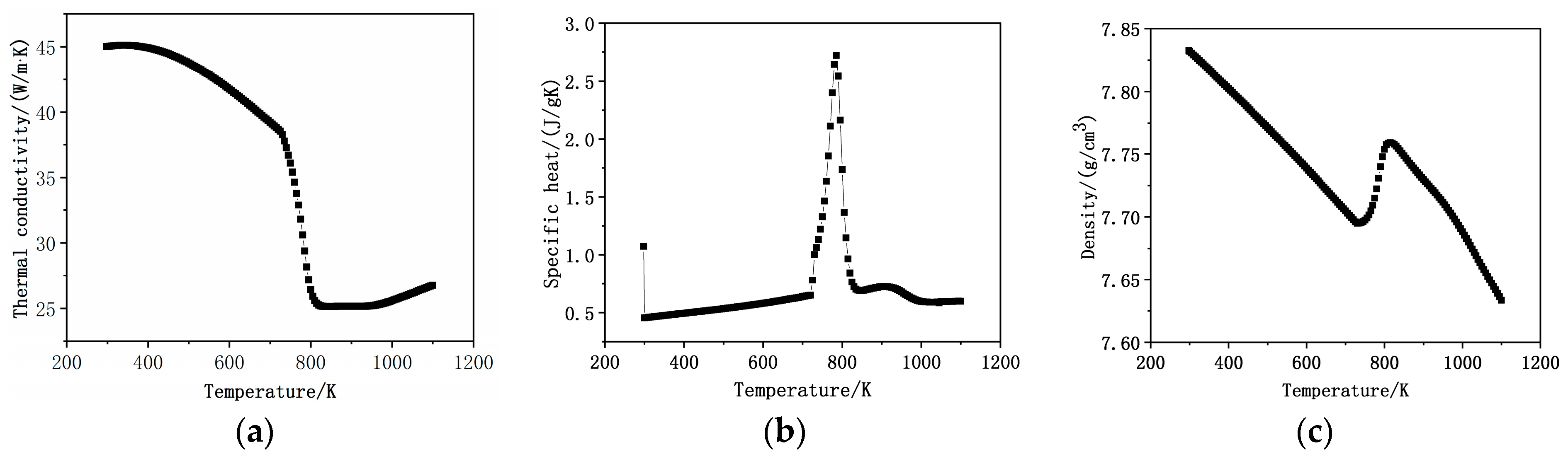
Figure 3.
Flow chart of multi-field multi-scale model.

Figure 4.
Schematic diagram of vacuum pulse carburizing stage.

Figure 5.
FEM model and mesh. (a) Schematic diagram of the sample; (b) Finite element mesh.
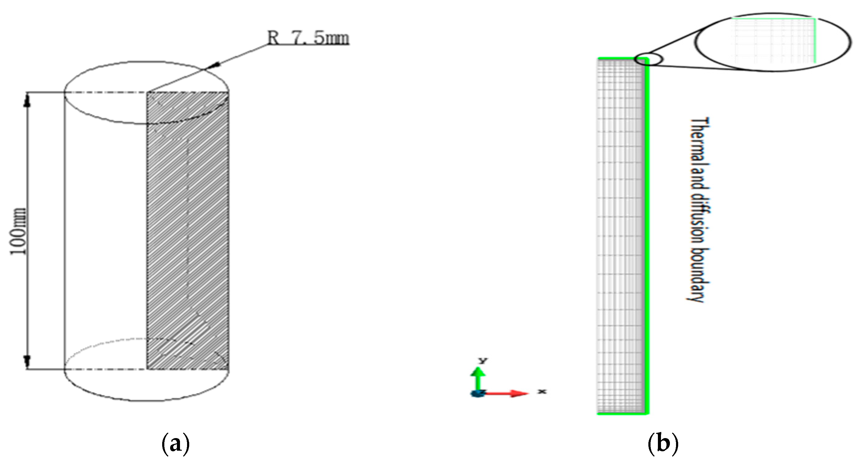
Figure 6.
Carbon concentration distribution. (a) Vacuum carburizing of process 1; (b) Vacuum carburizing of process 2.
Figure 6.
Carbon concentration distribution. (a) Vacuum carburizing of process 1; (b) Vacuum carburizing of process 2.

Figure 7.
Comparison of experimental and simulated carbon concentration distribution curves. (a) Vacuum carburizing of process 1; (b) Vacuum carburizing of process 2.
Figure 7.
Comparison of experimental and simulated carbon concentration distribution curves. (a) Vacuum carburizing of process 1; (b) Vacuum carburizing of process 2.

Figure 8.
Martensite and hardness content distribution of process 2. (a) Martensite; (b) Hardness.

Figure 9.
Microstructure of different parts after vacuum carburizing. (a) Surface; (b) Sub-Surface; (c) Center.
Figure 9.
Microstructure of different parts after vacuum carburizing. (a) Surface; (b) Sub-Surface; (c) Center.

Figure 10.
Inner and outer surface temperature change. (a) Location of point B and point A; (b) Temperature change.
Figure 10.
Inner and outer surface temperature change. (a) Location of point B and point A; (b) Temperature change.
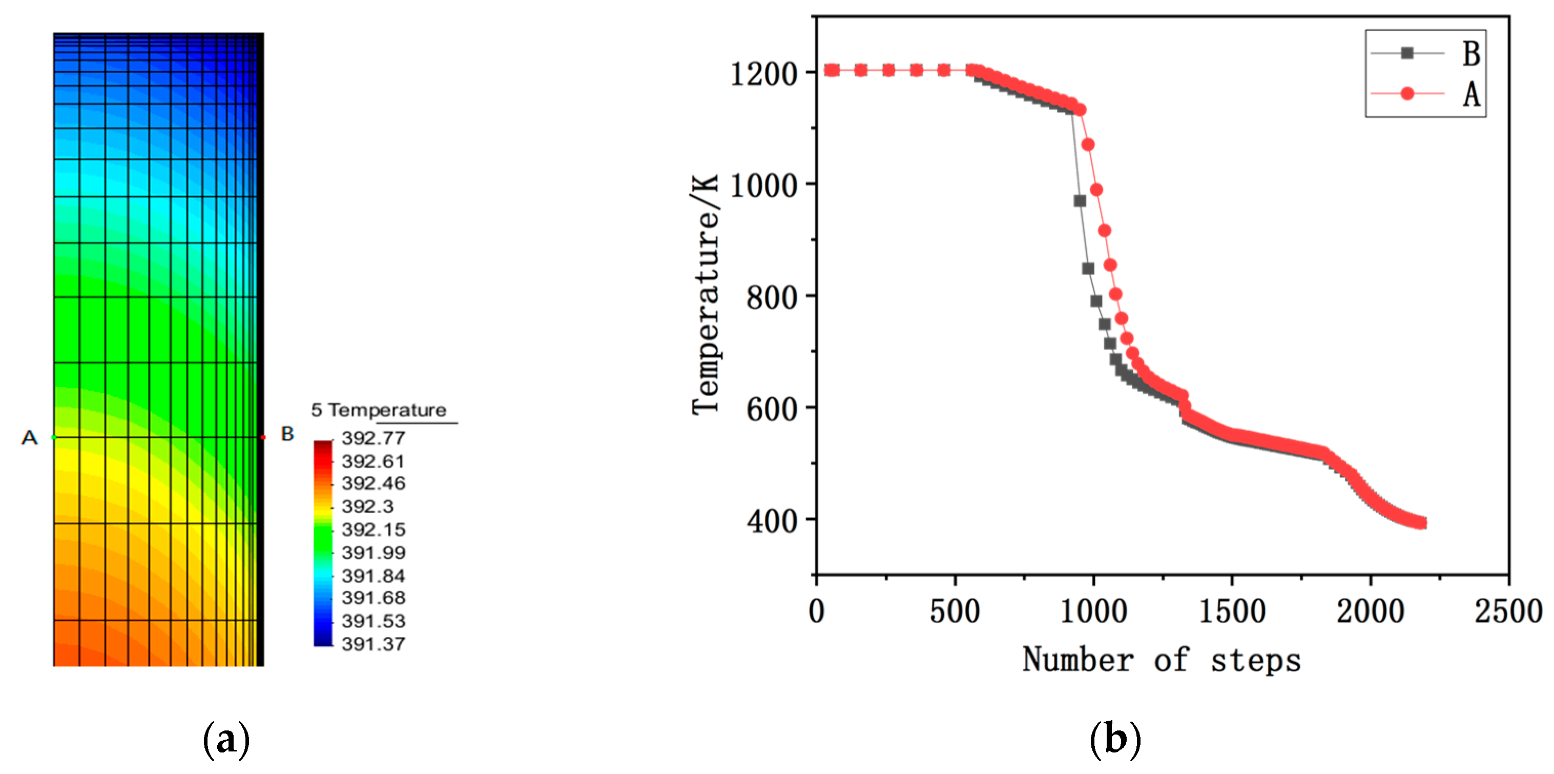
Figure 11.
Comparison of simulated and experimental surface hardness.

Figure 12.
Simulation of carbon content distribution with different diffusion times.


Table 1.
Chemical composition of 20CrMo steel (wt.%).
| Compositions | C | Si | Mn | Cr | Mo | P | S | Fe |
|---|---|---|---|---|---|---|---|---|
| Content | 0.2 | 0.25 | 0.76 | 1.04 | 0.24 | 0.014 | 0.017 | Bal. |
Table 2.
Mechanical properties of 20CrMo steel.
| Mechanical Properties | Tensile Strength | Yield Strength | Elongation | Section Shrinkage |
|---|---|---|---|---|
| Value | ≥885 MPa | ≥685 MPa | ≥12% | ≥50% |
Table 3.
Vacuum carburizing process scheme.
| Process No. | Austenitization Process | Vacuum Carburizing Process | Other Parameters | ||
|---|---|---|---|---|---|
| Carburizing Temperature/°C | Carburizing Time/min | Diffusion Time/min | |||
| 1 | Preheating: 650 °C × 30 min. After reaching carburizing temperature 930 °C × 30 min. | 930 | 42 | 0 | Carburizing pressure: 3 kPa. C2H2 and H2 flow rate: 8 L/min. Gas quenching pressure: 6 bar. |
| 2 | 930 | 42 | 140 | ||
Table 4.
Carbon concentration at different diffusion times.
| Number | Carburizing Time/min | Diffusion Time/min | Surface Carbon Concentration/% | Carburized Layer Depth/mm |
|---|---|---|---|---|
| L1 | 42 | 105 | 0.80 | 0.903 |
| L2 | 42 | 125 | 0.75 | 0.924 |
| L3 | 42 | 145 | 0.66 | 0.930 |
| L4 | 42 | 165 | 0.63 | 0.951 |
Publisher’s Note: MDPI stays neutral with regard to jurisdictional claims in published maps and institutional affiliations. |
© 2021 by the authors. Licensee MDPI, Basel, Switzerland. This article is an open access article distributed under the terms and conditions of the Creative Commons Attribution (CC BY) license (https://creativecommons.org/licenses/by/4.0/).
Share and Cite
MDPI and ACS Style
Guo, J.; Deng, X.; Wang, H.; Zhou, L.; Xu, Y.; Ju, D. Modeling and Simulation of Vacuum Low Pressure Carburizing Process in Gear Steel. Coatings 2021, 11, 1003. https://0-doi-org.brum.beds.ac.uk/10.3390/coatings11081003
AMA Style
Guo J, Deng X, Wang H, Zhou L, Xu Y, Ju D. Modeling and Simulation of Vacuum Low Pressure Carburizing Process in Gear Steel. Coatings. 2021; 11(8):1003. https://0-doi-org.brum.beds.ac.uk/10.3390/coatings11081003
Chicago/Turabian StyleGuo, Jingyu, Xiaohu Deng, Huizhen Wang, Leyu Zhou, Yueming Xu, and Dongying Ju. 2021. "Modeling and Simulation of Vacuum Low Pressure Carburizing Process in Gear Steel" Coatings 11, no. 8: 1003. https://0-doi-org.brum.beds.ac.uk/10.3390/coatings11081003
Note that from the first issue of 2016, this journal uses article numbers instead of page numbers. See further details here.