Article

Effects of the Ethyne Flow Ratio on Structures and Mechanical Properties of Reactive High Power Impulse Magnetron Sputtering Deposited Chromium-Carbon Films

Department of Mechanical and Computer Aided Engineering, National Formosa University, Huwei, Yunlin County 63201, Taiwan
*
Author to whom correspondence should be addressed.
Submission received: 30 June 2021 / Revised: 16 July 2021 / Accepted: 20 July 2021 / Published: 22 July 2021

Abstract

:
Chromium-carbon films were deposited by utilizing reactive high-power impulse magnetron sputtering with different mixture ratios of ethyne and argon with a constant deposition total pressure while the deposition temperature, pulse frequency, duty cycle and average power of the chromium cathode remain the same. The microstructure and chemical bonding of the obtained films within different composition were compared. The results show that with the increasing ethyne ratio, the carbon content in films increases linearly with two slopes. Moreover, the microstructure of the deposited film changes from a dense glassy structure into a columnar structure, even a clusters structure. The sp2-C bonding in films decreases but the Cr–C bonding increases with decreasing the ethyne ratio. This reveals the main phase of films changes from a hydrogenated amorphous carbon phase into a glassy amorphous chromium carbide phase. Such changes of the microstructure and phase cause a large difference on the film hardness and elasticity.

1. Introduction

By using plasma-enhanced physical vapor deposition techniques, various transition metal-contained carbon, metal carbides, carbon-contained alloys or multiphase composite metal-carbon films can be synthesized by tuning deposition parameters. Each phase exhibits individual electrical, mechanical, chemical properties and subsequent conductivity, tribology, corrosion resistance performance [1,2,3,4,5,6,7,8,9,10,11,12,13,14,15,16,17,18,19,20,21]. Amorphous carbon phases with high hardness/elastic modulus ratio and low surface energy provides a low friction wear resistance [12]. Carbide phases with the chemical bonding, which is a mixture of metallic, covalent, ionic characters, usually provide the high hardness, high moduli, chemical stability and low electrical resistivity [22]. Therefore, transition metal-carbon (TM-C) films have been widely used as the wear or the corrosion resistant protective coatings [6,9,20,23]. Some metal elements, such as chromium and aluminum, in these TM-C systems, form an extreme thin oxide layer to block the further oxidation and the other corrosive substances. Their potential in long service electrical contact applications has been demonstrated [13].
The Cr–C system has several interesting characteristics. For example, the hardness of the synthesized chromium carbide is varied up to ten times depending on the deposition processes and the composition [13,14,15]. The most unique property of the Cr–C system is the wide range glass forming ability [24,25,26,27,28]. This feature benefits tailoring the film structure and subsequent film functions by adjusting deposition conditions [10,29,30].
In our previous work, the experiment on depositing chromium-carbon films by utilizing reactive high-power impulse magnetron sputtering (HiPIMS) was carried out [31]. HiPIMS provides high degree ionization of the sputtered species. This enables the alteration of the kinetic energy of the incident ions and the mobility of the adatoms by controlling substrate biasing and the pulse power density [32,33,34,35]. Films with higher density and better functions can be therefore achieved with the cost of lower deposition rate. Cr–C films deposited at different synchronized substrate bias voltage and argon/ethyne gas flow ratio from 1:1 to 12:1 were compared in the previous work [31]. It was found that the main structure of all the obtained films in the previous work is hydrogenated amorphous carbon. Although applying synchronized substrate bias successfully prevented the substrate voltage drop and inhibited arc discharge on deposited film [31,36,37]. A part of films presents loosen structures which seemed contrary to above-mentioned features of denser films via HiPIMS. Enhancing the synchronized negative substrate bias voltage did improve the density and hardness of HiPIMS-deposited Cr–C films. However, all the obtained films hardness values were still relatively low while being compared with the results of the other studies [7,9,12,13,18,20]. Neither features of the glass forming nor transition from metal mode to compound mode depositions, which are commonly seen in direct current magnetron sputtering (dcMS) Cr–C system [12,25,28], were found. Therefore, the range of argon/ethyne gas flow ratio should be extended in order to fully discover the relationship between the film structure and the argon/ethyne gas flow ratio during the reactive HiPIMS deposition of Cr–C coatings. In this study, the films from Cr-rich to C-rich contents were deposited by using reactive HiPIMS technique. The microstructure and mechanical properties of the different films were compared to fully discover the relationship.

2. Materials and Methods

Cr–C films were deposited onto Si (100) wafer chips substrate in a HiPIMS deposition system. The substrates were placed facing the chromium target at a distance of 100 mm. One unipolar HiPIMS power supply (Hüttinger TruPlasma Unipolar 4001, TRUMPF, Ditzingen, Germany) were connected to the rectangle chromium cathode (432 mm × 76 mm × 13 mm) with an unbalanced magnetron. One unipolar substrate bias power supply (Hüttinger TruPlasma Bias 4010 G2, TRUMPF, Ditzingen, Germany) was connected to the substrate holder.
After vacuuming to the base pressure of 6 × 10⁻³ Pa, the argon was introduced into the chamber and the glow discharge plasma substrate cleaning was proceeded at 2.7 Pa by applying direct current −1000 V substrate bias voltage for 40 min. After argon glow discharge plasma cleaning, the pressure was further reduced to 0.8 Pa. The HiPIMS plasma was initiated on the Cr target and the −1000 V substrate bias voltage was switched to the unipolar pulsed mode and synchronized with the target HiPIMS pulses to proceed the Cr ion bombardment for 40 s. The reasons to apply the synchronized substrate bias can be seen in the other research [32,38] and our previous works [31,36,37]. Due to the recycling of ions and the flight delay of ions [33,38,39], the pulse width of the substrate bias voltage was set to 1.75-fold of HiPIMS pulses to optimally accelerate the Cr ion flux. The argon plasma cleaning and Cr ion bombardment generate heat in the substrate and raises the temperature to near 200 °C.
A series of different Cr–C films were deposited at a same total pressure of 0.8 Pa with various Ar/C2H2 gas flow ratio value, 10:1, 12:1, 14:1, 16:1, 24:1 and 38:1, respectively. The HiPIMS pulse voltage and current varied with the C2H2 gas flow ratio while keeping a constant average HiPIMS power of 3 kW. The synchronized substrate bias voltages were set to the same −150 V. The deposition time was 90 min. The deposition parameters are listed in Table 1.
The chemical bonding and compositions of the films were analyzed by using the electron spectroscopy for chemical analysis (ESCA, ULVAC-PHI, PHI 5000 VersaProbe, ULVAC-PHI, Chigasaki, Japan), also known as X-ray photoelectron spectroscopy (XPS), after the removal of surface contamination by conducting the 180 s argon ion bombardment. An X-ray diffractometer (XRD, D8 Discover X-ray diffractometer, Bruker, Billerica, MA, USA) with a Cu radiation source was used to characterize the crystallinity of the films. A Raman spectrometer (PROTRUSTECH, Tainan, Taiwan) was used to determine the presence of carbon phases in the Cr–C films. The surface and cross-sectional morphologies of deposited Cr–C films were observed by using a scanning electron microscope (SEM, S-4800 Cold Field Emission Scanning Electron Microscope, Hitachi, Tokyo, Japan). The film thickness was estimated from the SEM cross-sectional images. The thickness of obtained Cr–C films is between 2.1 to 2.9 μm. The hardness and the modulus of elasticity of Cr–C films were evaluated by applying the nanoindentation (TTX-NH3, Anton Paar, Graz, Austria). Settings of the analysis instruments were as the same as described in the previous works [31,36,37].

3. Results and Discussion

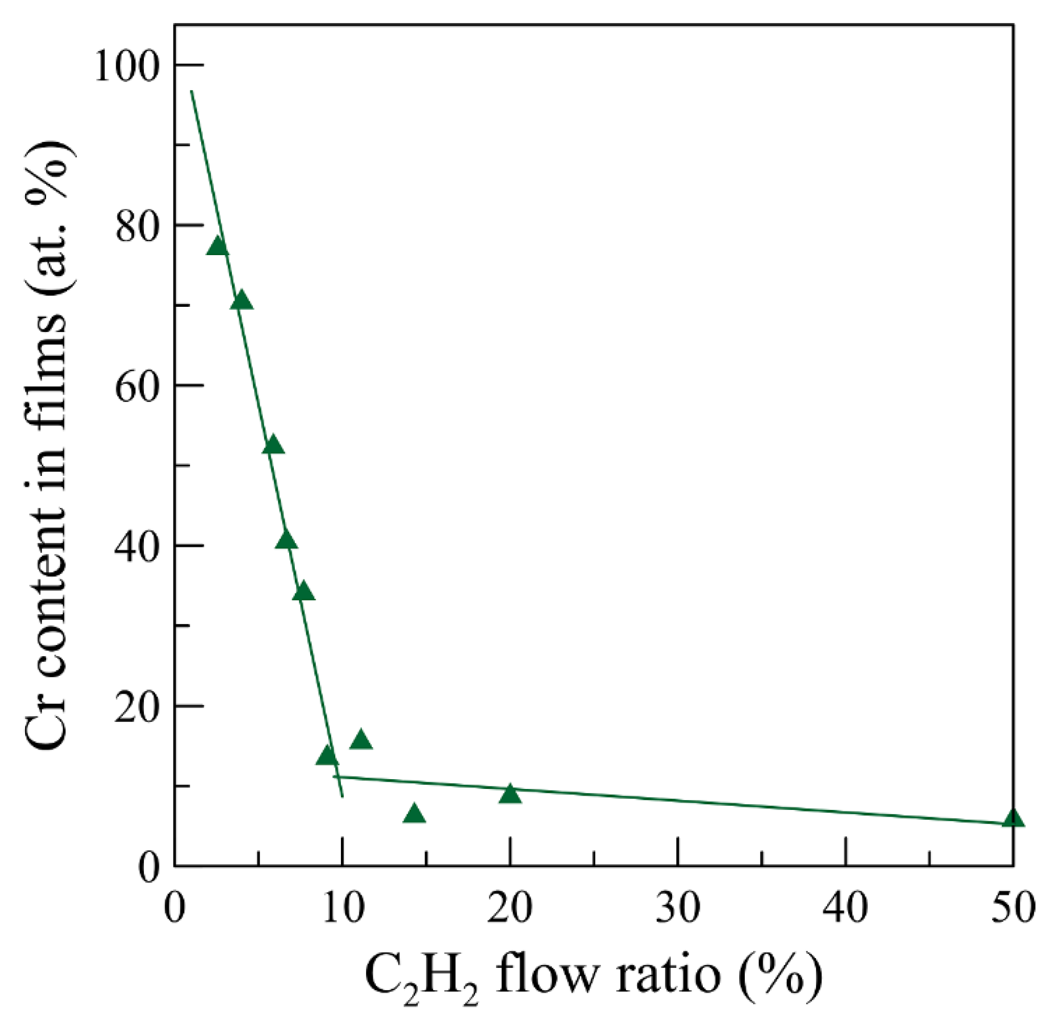
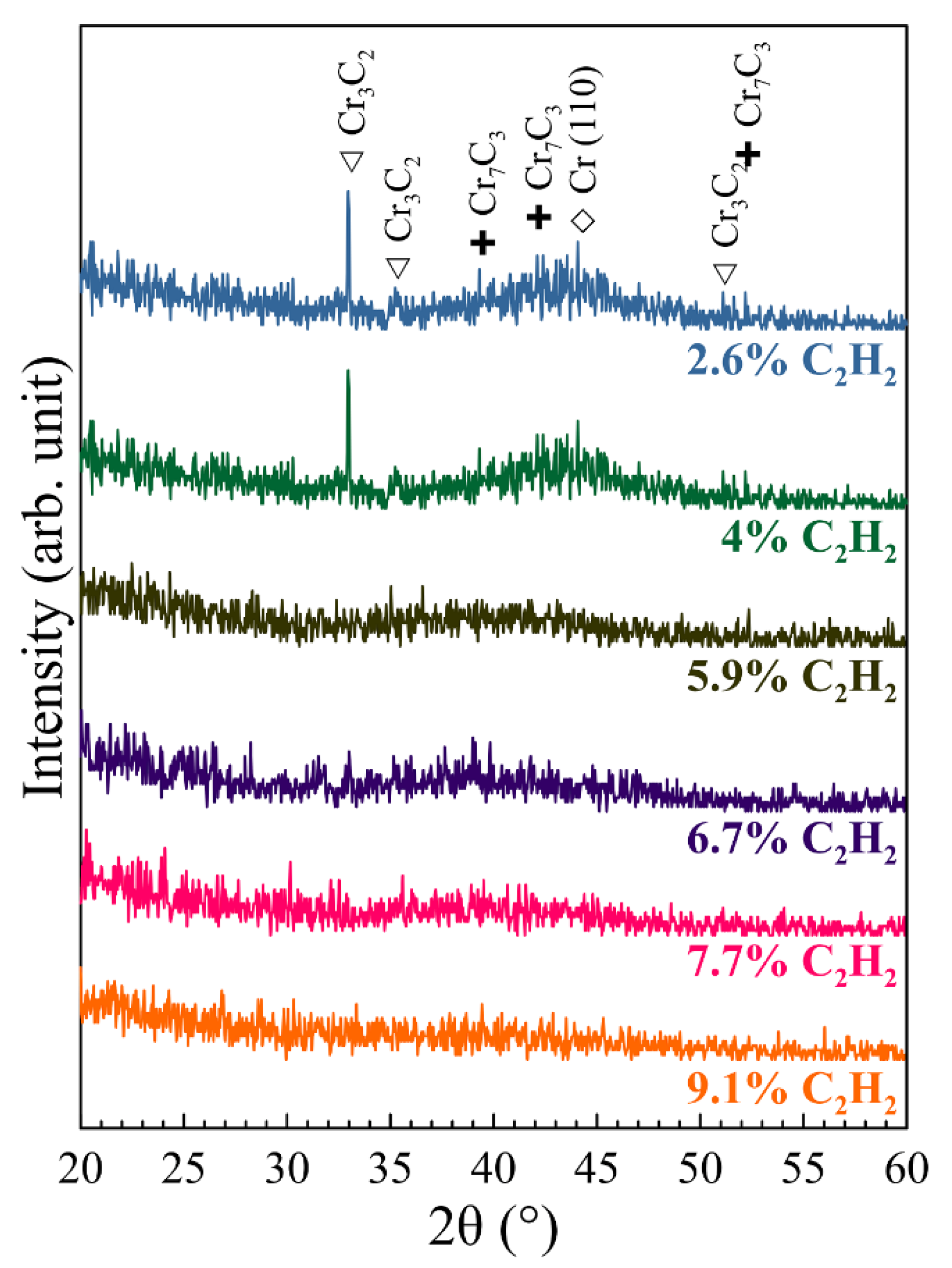
3.1. Composition and Crystallographic Orientation

The chromium contents in Cr–C films deposited at different C2H2 gas flow ratio are shown in Figure 1. Some results of the higher C2H2 gas flow ratio were collected from the previous work [31]. The Cr concentration in films decreases near linearly with the increasing the C2H2 gas flow ratio. However, there is slope transition occurred around Ar/C2H2 gas flow ratio 10:1. This is a common phenomenon of reactive dcMS with a metallic target [33,39,40]. As for low C2H2 gas flow rate, the reactive gas is not sufficient for all sputtered metal species. The target voltage shows no obvious change. The deposition is under the so-called metallic mode. However, when the C2H2 gas flow ratio reaches the critical value, the target voltage dramatically drops due to the target poisoning. Under this condition, the deposition transfers to the compound mode. Meanwhile, the release of sputtered metal species is reduced and the reactive gas becomes excessive. The composition of films deposited under the compound mode changes slightly with the reactive gas. This explains why most films obtained in our previous work presents a hydrogenated amorphous carbon main phase [31] and the pulse voltage varies greatly in this study (Table 1). However, these results seem against the impression that HiPIMS exhibits milder target poisoning due to the rarefaction of the reactive gas [33,41]. The mechanism is still unclear due to the complex interactions of each different metal, reactive gas, total pressure and pulse width [33].
The X-ray diffractograms of Cr–C films deposited at different C2H2 flow rate fractions are shown in Figure 2. All films of the Ar/C2H2 flow ratio from 10:1 and 38:1 with a Cr concentration from 16 at.% to 75 at.% exhibits a mainly X-ray amorphous structure. This result coincides with the series of studies which show that Cr–C films with an X-ray amorphous structure could be sputtering deposited in the entire composition range of 25–85 at.% C at 300 °C [10,12,24,25]. The amorphous Cr–C film may include two separate phases, amorphous chromium-rich carbide and amorphous carbon phases. It seems there are more weak and broad peaks of chromium and carbide phases shown in those Cr–C films with a relatively higher Cr concentration.
In Figure 2, a broad feature become visible at about 36°~51° 2θ when the chromium content reaches 27 at.% (7.7% C2H2 gas flow rate). The intensity of this broad feature increases with the decrease of C2H2 gas fraction and shifts from 39° to higher angle 44° when the carbon content reduced. This trend is consistent with the results in ref. [10]. Two possible factors that attributed this shift: the decreases of nanocrystalline high carbon phases, a-CrC and a-C:H and the increases of nanocrystalline high chromium phases, Cr7C3, Cr3C2 and Cr. The decrease of C2H2 flow rate causes the decrease of carbon content in films and results the presence of nanocrystalline high chromium phases. Although HiPIMS usually produces a higher ionization ratio and a −150 V substrate bias was applied to enhance the kinetic energy of the incident ions, the crystallinity of the deposited Cr–C films is still similar to those dcMS sputtering deposited amorphous Cr–C films. Similar cases could also be found in the comparison of Cr–C films deposited by reactive dcMS and HiPIMS [12]. Crystalline phases appeared when the dcMS sputtering deposition temperature was raised to 500 °C [24]. Furthermore, crystalline phases also can only be found in Cr–C films deposited by using cathodic arc deposition, which possess a fully ionized metal species, at over −350 V substrate bias [7]. Therefore, the substrate bias voltage applied in this study might not be sufficient to induce a crystalline structure.

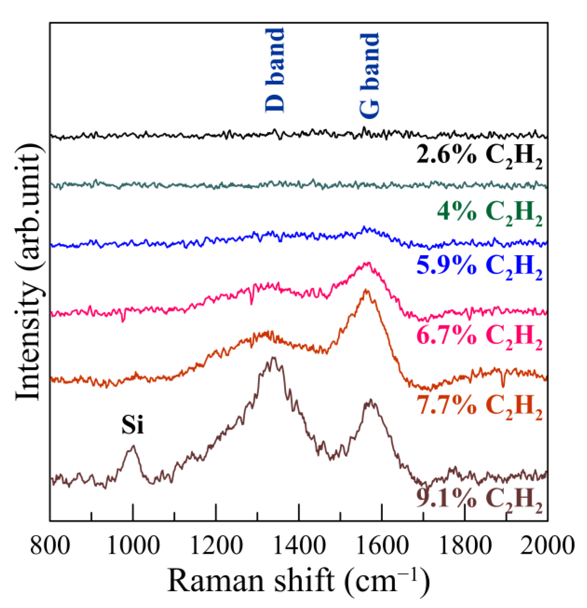
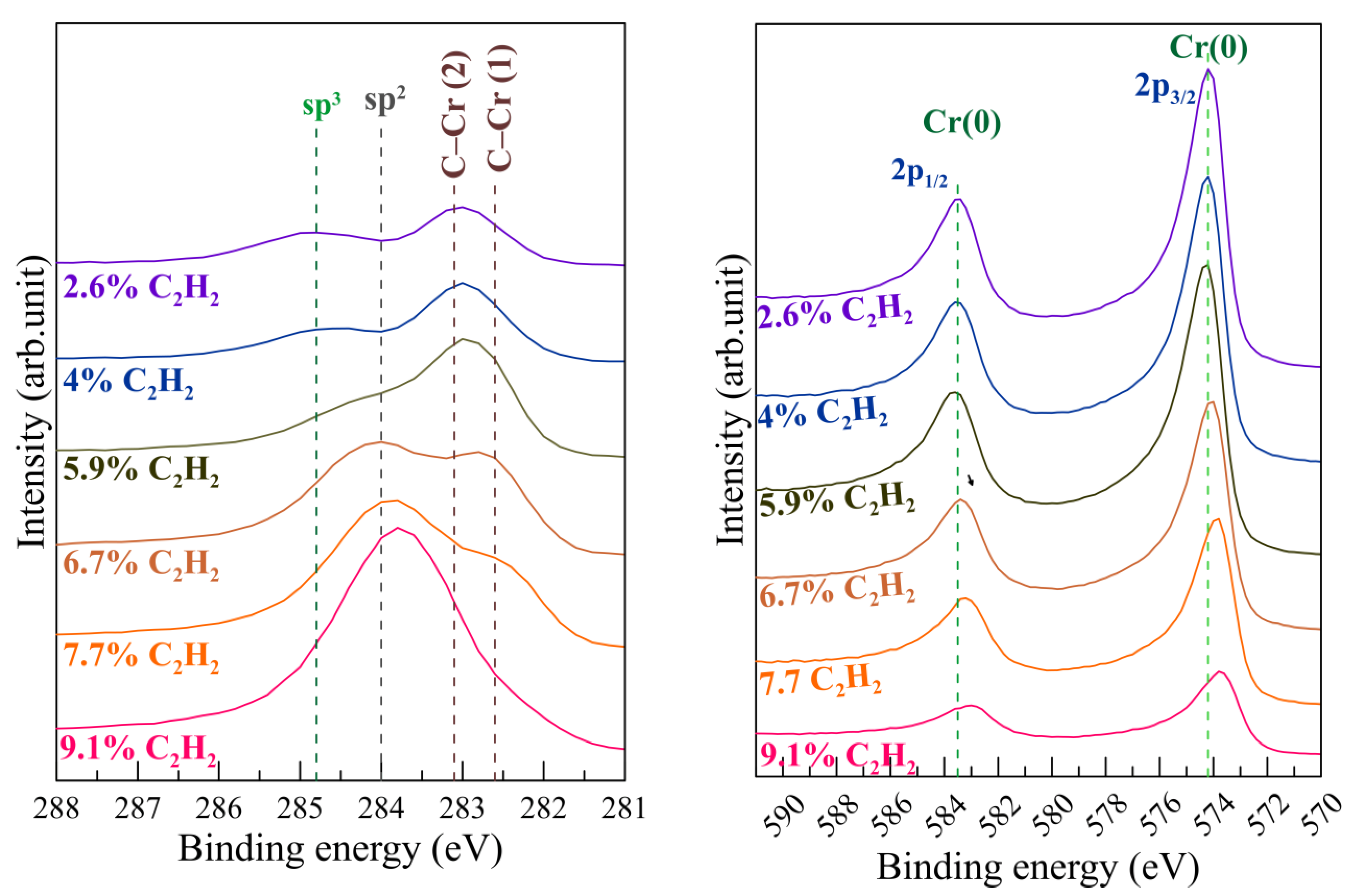
3.2. Chemical Bonding

The Raman spectra of the Cr–C films deposited at different C2H2 flow ratio are shown in Figure 3. Only peaks of G (~1580 cm−1) and D (~1350 cm−1) bands of carbon phases can be identified in Cr–C films deposited with a relatively higher C2H2 gas flow rate. These two peaks prove the presence of carbon phases in films with relatively higher carbon content. Intensities of both D and G bands decrease with the fraction of C2H2. That indicates the carbon phase reduce with the decrease of the carbon content in Cr–C films. Similar trend also can be found for Ti–C films deposited by using same HiPIMS power [42]. The intensity of D band decreases more obviously. This indicates the decrease of number and clustering of rings [43].
The ESCA (XPS) C1s and Cr2p spectra of Cr–C films deposited with different C2H2 gas flow ratios are shown in Figure 4. Due to the complex nature of the C1s spectra and the resolution limits of the equipment, the quantity of each component of different carbon cannot be estimated. Refer to ref. [24], the C1s is contributed by C–C bonds and C–Cr bonds. The C–C bonds includes sp2 and sp3 bonding and the C–Cr bonds might be contributed by C–Cr (1) and C–Cr (2) bonding, which correspond to Cr7C3 and Cr3C2 phase, respectively. It is obvious that main phase in high carbon films is the sp2 phase which decreases with reducing the carbon content in films. The carbide phases increase with reducing the C2H2 gas fraction and reaches to a maximum when the Cr concentration is over 52 at.% (5.9% C2H2 gas fraction), then decreases. This trend is consistent with the decrease of D and G bands in Raman spectra shown in Figure 3. The sp3-C phase decreases slightly with reducing the carbon content in films. These trends are similar to the results of Cr–C films deposited by non-reactive dcMS sputtering [10,24,30]. Similar results also can be found for Ti–C films deposited by using same HiPIMS power [42]. The bonding energy of sp2-C is relatively lower than that of sp3-C. This would favor the carbon atoms of sp2-C to combine with the chromium atoms to form the carbide phases [44]. This explains the significant decrease of sp2-C and the increase of carbide phases with reducing the carbon content in films. The increase of Cr2p intensity with the decrease of C2H2 gas fraction is consistent with the sharp slope in Figure 1. The bonding energies of two peaks also shift to higher value with the decrease of C2H2 gas fraction.

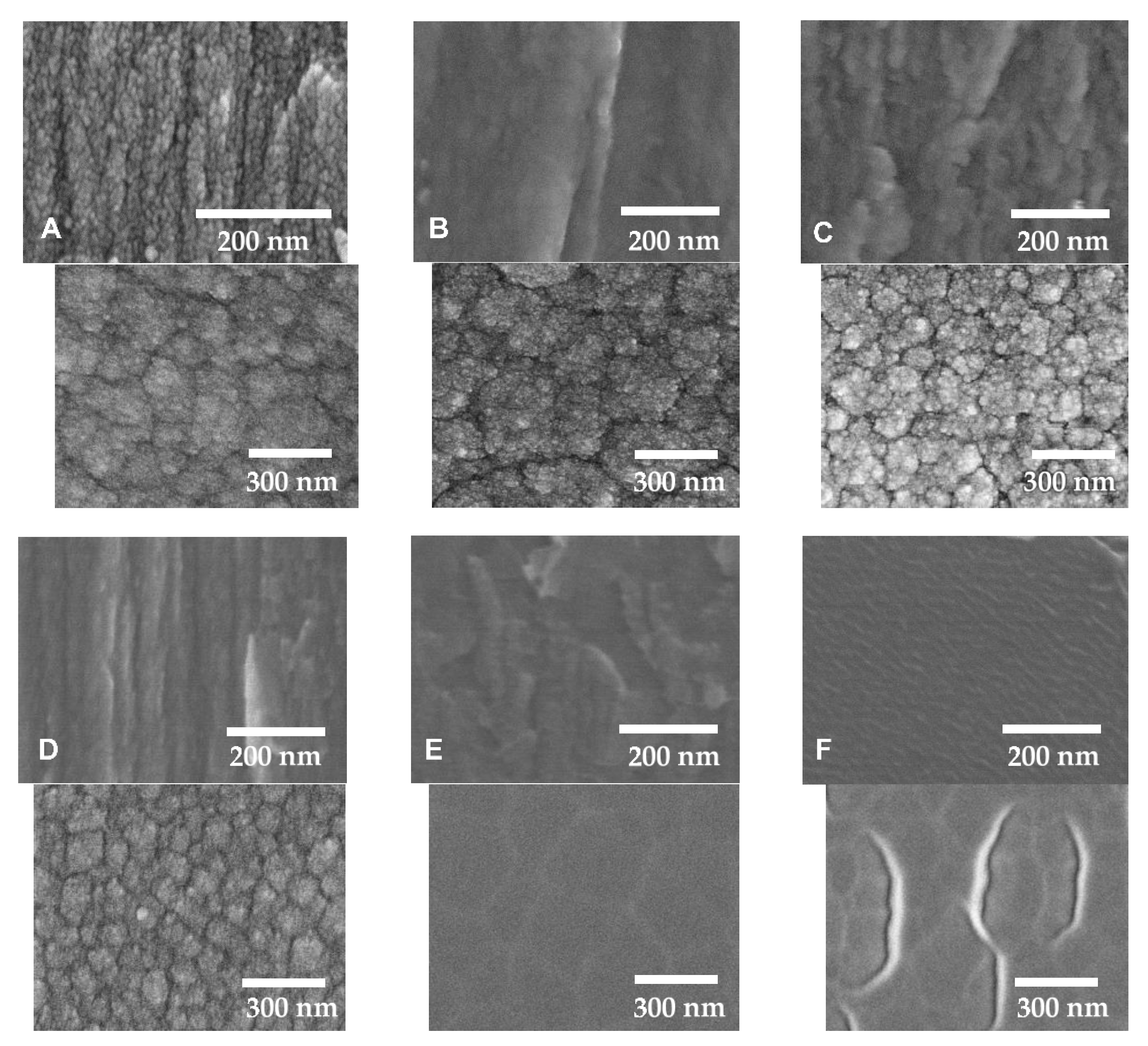
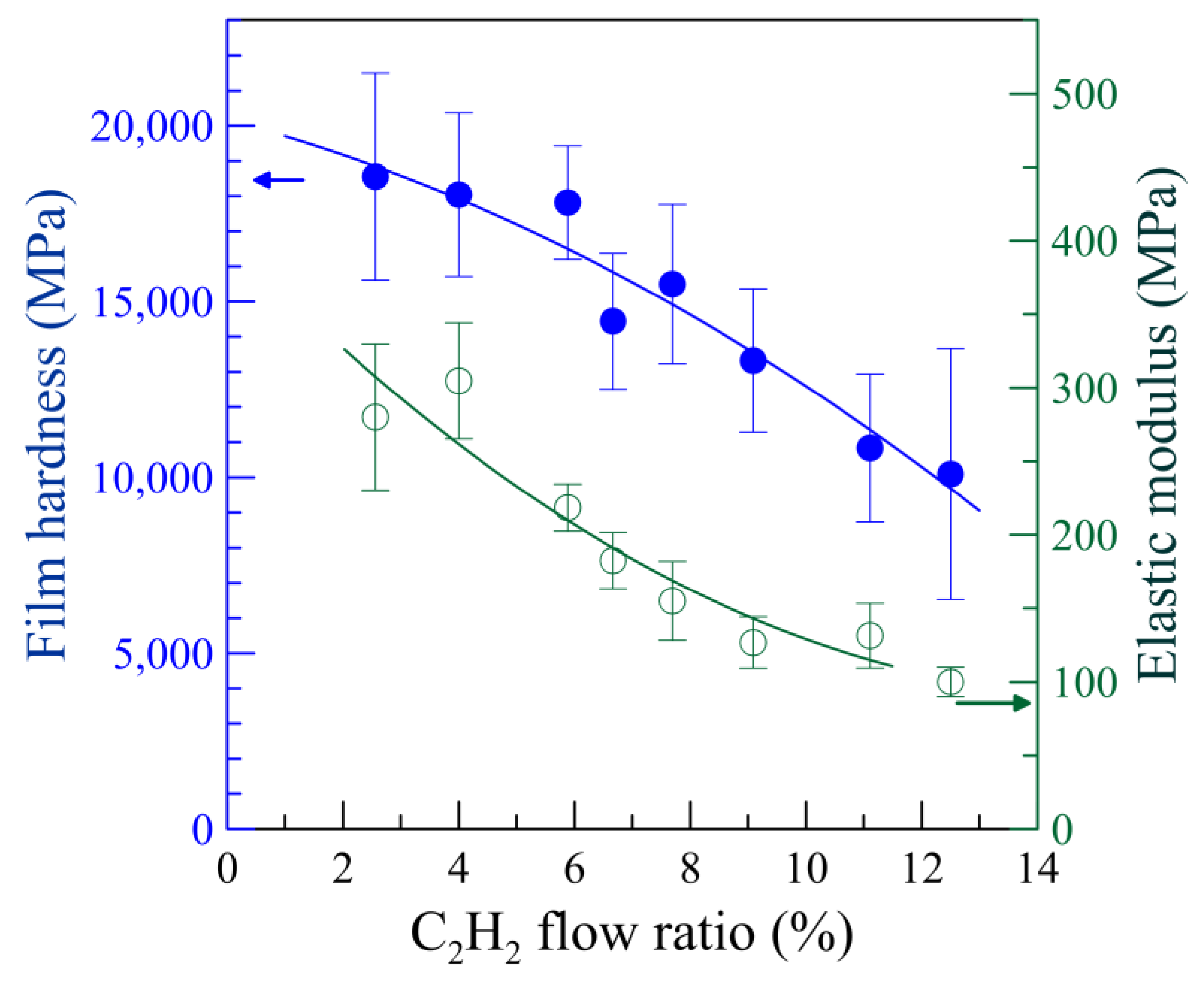
3.3. Microstructure and Mechanical Properties

The top and cross-sectional SEM SE micrographs of the Cr–C films deposited at the pressure of 0.8 Pa with different C2H2 gas fraction are shown in Figure 5. The film of 9.1% C2H2 gas fraction (Cr 16 at.%) presents a loosen columnar structure with a feature of stacking clusters. This structure is similar to the reported reactive HiPIMS-deposited [12,20] and non-reactive dcMS-deposited [10] Cr–C films with a high carbon content. With the C2H2 gas fraction decrease, the film structure transfers to relatively denser columns with round cauliflower tops until 5.9% C2H2 gas fraction (Cr 52 at.%) is reached. Meanwhile, no obvious granular edge was found between the columns. These are also similar to those medium chromium content films reported in ref. [10,12,20]. As for the films of 4% C2H2 gas fraction (Cr 66.6 at.%) and 2.6% C2H2 gas fraction (Cr 75 at.%), the film morphologies change drastically. No columnar feature can be found on the top and on the cross-sectional of these two films. The top of two films is flat with a feature of segregation phase surrounding the boundary of the matrix domains. The segregation phase in the boundary could be amorphous carbon and the surrounded matrix could be amorphous carbide phase [25]. The cross-section of two films is also as flat as the cleaved glass. All these features are commonly seen in amorphous films deposited at low temperature or a high cooling rate. These features support the results of X-ray diffraction. There are intergranular cracks on the film of 2.6% C2H2 gas fraction (Cr 75 at.%), which might be induced by the huge internal stress and the difference of the elastic moduli between the carbon and carbide phases.
As mentioned in Introduction, the amorphous carbon phases usually exhibit a high hardness/elastic modulus ratio and the carbide phases usually exhibit both high hardness and high elastic modulus. The fraction changes of the carbon and carbide phases in Cr–C film can significantly affect the mechanical properties of films [12,13,15].
The average hardness and the elastic modulus of Cr–C films deposited at different C2H2 gas fractions measured by the nanoindentation are shown in Figure 6. Both the harness and elastic modulus increases with the decrease of the C2H2 gas fraction and the carbon content. The trend and values are very similar to the Cr–C films deposited by using the reactive dcMS under the Ar/CH4 mixture atmosphere [15]. In ref. [10], it was concluded that both the film hardness and the film elasticity increase with the fraction of C–Cr bonds in film deposited by using dcMS. In the ref. [12], it was found that both the film hardness and the film elasticity decrease with the fraction of a-C:H phase in films deposited by dcMS and HiPIMS. These similar relationships of mechanical properties on the fraction of the carbon and carbide phases are consistent with the chemical analysis results in the previous section. The large measurement deviations could be attributed to the microscale non-uniform coexistence of the multiple phases, including a-CrC, a-C:H, nanocrystalline carbide, chromium and droplets, in the film structure [31]. The loosen structure of the amorphous carbon films deposited under the excess C2H2 gas fraction and the compound mode target behavior show the lowest film hardness and the largest deviation value. Decreasing the C2H2 flow rate in the deposition atmosphere reduces the carbon content in the deposited films. This promotes the formation of carbide and consequently enhances the film hardness and elasticity. However, the hardness/elastic modulus (H/E) ratio, which is an indicator to better wear resistance [45], also decreases with the carbon phases. This results in the loss of adaptation of strain and may cause the intergranular cracks shown in Figure 5F.

4. Conclusions

In this research, chromium-carbon films were deposited by utilizing reactive high-power impulse magnetron sputtering under the same condition of deposition temperature, pulse frequency, duty cycle, average power of the chromium cathode, but with different mixture ratios of ethyne and argon with a constant deposition total pressure of 0.8 Pa. After investigating the microstructure, composition and chemical bonding of the obtained films, several conclusions are made. In the range of the C2H2 gas fraction used in this work, all obtained Cr–C films are X-ray amorphous. With the C2H2 gas ratio decrease, the chromium concentration in films increases linearly with two slopes, which can be attributed to the metallic mode deposition and compound mode deposition respectively. With the chromium concentration increase, the microstructure of the obtained film changes from a loosen staking-clusters structure into a columnar structure, and then a dense glassy structure. Moreover, the sp2-C bonding decreases, but the Cr–C bonding increases with the carbon content decrease. This proves that the main phase of the films changes from a hydrogenated amorphous carbon phase into the glassy amorphous chromium carbide. These changes of the microstructure and phases cause a large difference in the film hardness. The increase of amorphous carbide phases results in the higher hardness and the higher elastic modulus.

Author Contributions

Conceptualization, C.-C.K.; data curation, S.-P.C.; funding acquisition, C.-C.K.; investigation, C.-C.K.; methodology, C.-C.K.; project administration, C.-C.K.; resources, C.-C.K.; writing—original draft, C.-C.K. All authors have read and agreed to the published version of the manuscript.

Funding

This research received no external funding.

Institutional Review Board Statement

Not applicable.

Informed Consent Statement

Not applicable.

Data Availability Statement

Not applicable.

Acknowledgments

The authors wish to thank Supati Cooperation for financial support. Precision Instrument Support Center of Feng Chia University and The Central Regional Instrument Center of National Chung Hsing University are also acknowledged for the microstructure analysis instruments.

Conflicts of Interest

The authors declare no conflict of interest.

References

  1. Pierson, H.O. Handbook of Refractory Carbides and Nitrides, 1st ed.; Noyes Publications: Park Ridge, NJ, USA, 1996; pp. 100–116. [Google Scholar]
  2. Oyama, S.T. The Chemistry of Transition Metal Carbides and Nitrides; Springer: Dordrecht, The Netherlands, 1996; pp. 28–52. [Google Scholar] [CrossRef]
  3. Nedfors, N.; Tengstrand, O.; Lewin, E.; Furlan, A.; Eklund, P.; Hultman, L.; Jansson, U. Structural, mechanical and electrical-contact properties of nanocrystalline-NbC/amorphous-C coatings deposited by magnetron sputtering. Surf. Coat. Technol. 2011, 206, 354–359. [Google Scholar] [CrossRef] [Green Version]
  4. Lewin, E.; Wilhelmsson, O.; Jansson, U. Nanocomposite nc-TiC/a-C thin films for electrical contact applications. J. Appl. Phys. 2006, 100, 054303. [Google Scholar] [CrossRef]
  5. Aubert, A.; Gillet, R.; Gaucher, A.; Terrat, J.P. Hard chrome coatings deposited by physical vapour deposition. Thin Solid Films 1983, 108, 165–172. [Google Scholar] [CrossRef]
  6. Merl, D.K.; Panjan, P.; Čekada, M.; Maček, M. The corrosion behavior of Cr-(C,N) PVD hard coatings deposited on various substrates. Electrochim. Acta. 2004, 49, 1527–1533. [Google Scholar] [CrossRef]
  7. Lin, C.C.; Lee, J.W.; Chang, K.L.; Hsieh, W.J.; Wang, C.Y.; Chang, Y.A.; Shih, H.C. The effect of the substrate bias voltage on the mechanical and corrosion properties of chromium carbide thin films by filtered cathodic vacuum arc deposition. Surf. Coat. Technol. 2006, 200, 2679–2685. [Google Scholar] [CrossRef]
  8. Edigaryan, A.A.; Safonov, V.A.; Lubnin, E.N.; Vykhodtseva, L.N.; Chusova, G.E.; Polukarov, Y.M. Properties and preparation of amorphous chromium carbide electroplates. Electrochim. Acta. 2002, 47, 2775–2786. [Google Scholar] [CrossRef]
  9. Esteve, J.; Romero, J.; Gómez, M.; Lousa, A. Cathodic chromium carbide coatings for molding die applications. Surf. Coat. Technol. 2004, 188–189, 506–510. [Google Scholar] [CrossRef]
  10. Andersson, M.; Högström, J.; Urbonaite, S.; Furlan, A.; Nyholm LJansson, U. Deposition and characterization of magnetron sputtered amorphous Cr–C films. Vacuum 2012, 86, 1408–1416. [Google Scholar] [CrossRef]
  11. Maréchal, N.; Quesnel, E.; Pauleau, Y. Deposition process and characterization of chromium-carbon coatings produced by direct sputtering of a magnetron chromium carbide target. J. Mater. Res. 1994, 9, 1820–1828. [Google Scholar] [CrossRef]
  12. Nygren, K.; Samuelsson, M.; Flink, A.; Ljungcrantz, H.; Rudolphi, Å.K.; Jansson, U. Growth and characterization of chromium carbide films deposited by high rate reactive magnetron sputtering for electrical contact applications. Surf. Coat. Technol. 2014, 260, 326–334. [Google Scholar] [CrossRef]
  13. Dai, W.; Wu, G.; Wang, A. Structure and elastic recovery of Cr–C:H films deposited by a reactive magnetron sputtering technique. Appl. Surf. Sci. 2010, 257, 244–248. [Google Scholar] [CrossRef]
  14. Ziebert, C.; Ye, J.; Stüber, M.; Ulrich, S.; Edinger, M.; Barzen, I. Ion bombardment-induced nanocrystallization of magnetron-sputtered chromium carbide thin films. Surf. Coat. Technol. 2011, 205, 4844–4849. [Google Scholar] [CrossRef]
  15. Gassner, G.; Mayrhofer, P.H.; Mitterer, C.; Kiefer, J. Structure-property relations in Cr–C/a-C:H coatings deposited by reactive magnetron sputtering. Surf. Coat. Technol. 2005, 200, 1147–1150. [Google Scholar] [CrossRef]
  16. Poletika, I.M.; Ivanov, S.F.; Gnyusov SF& Perovskaya, M.V. Electron-beam deposition of chromium carbide–based coatings with an ultradispersed structure or a nanostructure. Russ. Metall. 2016, 1275–1282. [Google Scholar] [CrossRef]
  17. Wolfe, D.E.; Singh, J.; Narasimhan, K. Synthesis of titanium carbide/chromium carbide multilayers by the co-evaporation of multiple ingots by electron beam physical vapor deposition. Surf. Coat. Technol. 2002, 160, 206–218. [Google Scholar] [CrossRef]
  18. Li, Z.-L.; Chen, Y.-Y.; Wang, C.-J.; Lee, J.-W. Comparison of chromium carbide thin films grown by different power supply systems. Surf. Coat. Technol. 2018, 353, 329–338. [Google Scholar] [CrossRef]
  19. Konishi, T.; Yukimura, K.; Takaki, K. Fabrication of diamond-like carbon films using short-pulse HiPIMS. Surf. Coat. Technol. 2016, 286, 239–245. [Google Scholar] [CrossRef]
  20. Tillmann, W.; Dias, N.F.L.; Stangier, D. Tribo-mechanical properties of CrC/a-C thin films sequentially deposited by HiPIMS and mfMS. Surf. Coat. Technol. 2018, 335, 173–180. [Google Scholar] [CrossRef]
  21. Richert, M.; Mazurkiewicz, A.; Smolik, J. Chromium carbide coatings obtained by the hybrid PVD methods. J. Achiev. Mater. Manuf. Eng. 2010, 43, 145–152. [Google Scholar]
  22. Jiang, C. First-principles study of structural, elastic, and electronic properties of chromium carbides. Appl. Phys. Lett. 2008, 92, 041909. [Google Scholar] [CrossRef]
  23. Bauer-Grosse, E. Thermal stability and crystallization studies of amorphous TM–C films. Thin Solid Films 2004, 447–448, 311–315. [Google Scholar] [CrossRef]
  24. Nygren, K.; Andersson, M.; Högström, J.; Fredriksson, W.; Edström, K.; Nyholm, L.; Jansson, U. Influence of deposition temperature and amorphous carbon on microstructure and oxidation resistance of magnetron sputtered nanocomposite CrC films. Appl. Surf. Sci. 2014, 305, 143–153. [Google Scholar] [CrossRef]
  25. Jansson, U.; Lewin, E. Sputter deposition of transition-metal carbide films—A critical review from a chemical perspective. Thin Solid Films 2013, 536, 1–24. [Google Scholar] [CrossRef]
  26. Cheng, Y.Q.; Ma, E. Atomic-level structure and structure–property relationship in metallic glasses. Prog. Mat. Sci. 2011, 56, 379–473. [Google Scholar] [CrossRef]
  27. Bauer-Grosse, E.; Aouni, A. Glass-forming range and glass thermal stability in binary 3d TM–C systems. J. Non-Cryst. Solids 2007, 353, 3644–3649. [Google Scholar] [CrossRef]
  28. Music, D.; Kreissig, U.; Mertens, R.; Schneider, J.M. Electronic structure and mechanical properties of Cr7C3. Phys. Lett. A 2004, 326, 473–476. [Google Scholar] [CrossRef]
  29. Magnuson, M.; Andersson, M.; Lu, J.; Hultman, L.; Jansson, U. Electronic structure and chemical bonding of amorphous chromium carbide thin films. J. Phys. Condens. Matter 2012, 24, 225004. [Google Scholar] [CrossRef] [Green Version]
  30. Groudeva-Zotova, S.; Vitchev, R.G.; Blanpain, B. Phase composition of Cr–C thin films deposited by a double magnetron sputtering system. Surf. Interface Anal. 2000, 30, 544–548. [Google Scholar] [CrossRef]
  31. Kuo, C.C.; Lin, C.H.; Chang, J.T.; Lin, Y.T. Reactive High Power Impulse Magnetron Sputtering of Chromium-Carbon Films. Coatings 2020, 10, 1269. [Google Scholar] [CrossRef]
  32. Lundin, D.; Minea, T.; Gudmundsson, J.T. High Power Impulse Magnetron Sputtering: Fundamentals, Technologies, Challenges and Applications; Elsevier: Amsterdam, The Netherlands, 2019. [Google Scholar] [CrossRef] [Green Version]
  33. Anders, A. Tutorial: Reactive high power impulse magnetron sputtering (R-HiPIMS). J. Appl. Phys. 2017, 121, 171101. [Google Scholar] [CrossRef] [Green Version]
  34. Kouznetsov, V.; Macak, K.; Schneider, J.; Helmersson, U.; Petrov, I. Hybrid HIPIMS and DC magnetron sputtering deposition of TiN coatings: Deposition rate, structure and tribological properties. Surf. Coat. Technol. 1999, 12, 290. [Google Scholar] [CrossRef]
  35. Machunze, R.; Ehiasarian, A.; Tichelaar, F.; Janssen, G.; Ehiasarian, A. Stress and texture in HIPIMS TiN thin films. Thin Solid Films 2009, 518, 1561–1565. [Google Scholar] [CrossRef]
  36. Kuo, C.C.; Lin, C.H.; Lin, Y.T.; Chang, J.T. Effects of cathode voltage pulse width in high power impulse magnetron sputtering on the deposited chromium thin films. Coatings 2020, 10, 542. [Google Scholar] [CrossRef]
  37. Kuo, C.C.; Lin, C.H.; Chang, J.T.; Lin, Y.T. Effect of voltage pulse width and synchronized substrate bias in high power impulse magnetron sputtering of zirconium films. Coatings 2021, 11, 7. [Google Scholar] [CrossRef]
  38. Greczynski, G.; Lu, J.; Jensen, J.; Bolz, S.; Kölker, W.; Schiffers, C.; Lemmer, O.; Greene, J.E.; Hultman, L. A review of metal-ion-flux-controlled growth of metastable TiAlN by HIPIMS/DCMS co-sputtering. Surf. Coat. Technol. 2014, 257, 15–25. [Google Scholar] [CrossRef] [Green Version]
  39. Carneiro, J.O.; Machado, F.; Rebouta, L.; Vasilevskiy, M.I.; Lanceros-Méndez, S.; Teixeira, V.; Costa, M.F.; Samantilleke, A.P. Compositional, optical and electrical characteristics of SiOx thin films deposited by reactive pulsed DC magnetron sputtering. Coatings 2019, 9, 468. [Google Scholar] [CrossRef] [Green Version]
  40. Saringer, C.; Franz, R. Effect of discharge power on target poisoning and coating properties in reactive magnetron sputter deposition of TiN. J. Vac. Sci. Technol. A 2016, 34, 041517. [Google Scholar] [CrossRef]
  41. Horwat, D.; Anders, A. Compression and strong rarefaction in high power impulse magnetron sputtering discharges. J. Appl. Phys. 2010, 108, 123306. [Google Scholar] [CrossRef] [Green Version]
  42. Jiang, X.; Yang, F.-C.; Lee, J.-W.; Chang, C.-L. Effect of an optical emission spectrometer feedback-controlled method on the characterizations of nc-TiC/a-C:H coated by high power impulse magnetron sputtering. Diam. Relat. Mater. 2017, 73, 19–24. [Google Scholar] [CrossRef]
  43. Ferrari, A.C.; Robertson, J. Interpretation of Raman spectra of disordered and amorphous carbon. Phys. Rev. B 2000, 61, 14095–14107. [Google Scholar] [CrossRef] [Green Version]
  44. Dai, W.; Ke, P.; Wang, A. Microstructure and property evolution of Cr-DLC films with different Cr content deposited by a hybrid beam technique. Vacuum 2011, 85, 792–797. [Google Scholar] [CrossRef]
  45. Leyland, A.; Matthews, A. Design criteria for wear-resistant nanostructured and glassy-metal coatings. Surf. Coat. Technol. 2004, 177–178, 317–324. [Google Scholar] [CrossRef]
Figure 1. Cr atomic concentration in deposited Cr–C film as a function of C2H2 gas fraction in 0.8 Pa deposition atmosphere.
Coatings 11 00873 g001
Figure 2. X-ray diffractograms of Cr–C films deposited on Si (100) at 0.8 Pa deposition atmosphere with different C2H2 fractions with applying a substrate bias of −150 V.
Coatings 11 00873 g002
Figure 3. Raman spectra of Cr–C films deposited on the Si (100) substrate with a substrate bias of −150 V at 0.8 Pa deposition atmosphere with different C2H2 fractions.
Coatings 11 00873 g003
Figure 4. The ESCA (XPS) C1s (left) and Cr2p (right) spectra of Cr–C films deposited on the Si (100) substrate with a substrate bias of −150 V at 0.8 Pa deposition atmosphere with different C2H2 gas fractions.
Coatings 11 00873 g004
Figure 5. The top (up) and cross-sectional (down) SEM SE micrographs of Cr–C films deposited on Si (100) substrate at 0.8 Pa deposition atmosphere of (A) 9.1%, (B) 7.7%, (C) 6.7%, (D) 5.9%, (E) 4% and (F) 2.6% C2H2 gas fraction with a substrate bias of −150 V.
Coatings 11 00873 g005
Figure 6. Mean values and standard deviations for nanoindentation hardness (H) and elastic modulus (E) for Cr–C films deposited on the Si (100) substrate with a substrate bias of −150 V at 0.8 Pa deposition atmosphere with different C2H2 gas fractions.
Coatings 11 00873 g006
Table 1. Parameters for the deposition of chromium-carbon films.
Deposition ParametersValue
AtmospherePressure (Pa)0.8
Ar/C2H2 gas flow ratio10:1 (9.1% C2H2), 12:1 (7.7% C2H2),
14:1 (6.7% C2H2), 16:1 (5.9% C2H2), 24:1 (4% C2H2), 38:1 (2.6% C2H2)
Target HiPIMS powerAverage power (kW)3
Peak voltage (V)−518~−988
Peak current (A)254~194
Pulse frequency (Hz)332
Pulse width (μs)60 (duty cycle 2%)
Cr ion bombardmentSynchronized bias voltage−1000 V (pulse width 105 μs)
Bombardment time40 s
Cr–C film depositionSynchronized bias voltage−150 V (pulse width 105 μs)
Deposition time90 min
Deposition temperature (°C)200
Notes: high-power impulse magnetron sputtering (HiPIMS).
Publisher’s Note: MDPI stays neutral with regard to jurisdictional claims in published maps and institutional affiliations.

