Article

The Investigation of Microstructure, Photocatalysis and Corrosion Resistance of C-Doped Ti–O Films Fabricated by Reactive Magnetron Sputtering Deposition with CO2 Gas

1
Special Glass Key Lab of Hainan Province, Hainan University, Haikou 570228, China
2
School of Science, Hainan University, Haikou 570228, China
3
School of Materials Science and Engineering, Hainan University, Haikou 570228, China
4
Department of Advanced Production Engineering, Engineering and Technology Institute Groningen, Faculty of Science and Engineering, University of Groningen, Nijenborgh 4, 9747 AG Groningen, The Netherlands
*
Author to whom correspondence should be addressed.
Submission received: 12 June 2021 / Revised: 19 July 2021 / Accepted: 20 July 2021 / Published: 23 July 2021
(This article belongs to the Special Issue Magnetron Sputtering Deposition of Thin Films)

Abstract

:
By employing carbon dioxide as one source of reaction gases, carbon-doped Ti–O films were fabricated via reactive magnetron sputtering deposition. The chemical bonding configurations and microstructure of the films were analyzed by Raman spectrum and SEM, respectively. The effect of pH on the photocatalytic activities of the films was determined via evaluation of the decolorization rate of methyl orange under alkali, acid and neutrality conditions using UV light irradiation. Electrochemical impedance spectroscopy and potentiodynamic polarization tests were employed to determine the anti-corrosion properties. Compared with the C-free Ti–O film, the C-doped Ti–O films exhibit superior corrosion resistance. Furthermore, the results of the photodegradation experiment suggest that the C-doped Ti–O films have excellent photocatalytic activities and, for methyl orange, those with higher carbon content exhibit hyper-photodegradative effect under the alkali condition.

1. Introduction

Currently, environmental pollution is becoming a serious issue worldwide, which is leading to increasing interest in the study of environmental purification materials [1,2].
Titanium dioxide (TiO2), as one type of semiconductor material, exhibits significant advantages in tackling toxic, refractory organic dye compounds and inorganic oxidations owing to its photocatalytic activity, excellent biological and chemical stability, and nonpolluting characteristics [3,4]. The key factors for high photocatalytic TiO2 are the capabilities to extend the lifetime of the hole and to decrease the recombination rate of photogenerated electron–hole pairs to form the hydroxyl radical. The production of substantial quantities of the hydroxyl radical assisted by TiO2 photocatalyst is essential for truly effective pollutant decomposition [5,6,7,8].
Many researchers attempted to modify TiO2 to obtain superior photocatalytic activity, including heterojunction, doping, dye sensitization, noble metal deposition and coupled semiconductors [5,9,10,11,12,13,14,15]. However, it has been proven that by decreasing the bandgap energy of TiO2 through doping, a wide range of solar spectra can be excited, and electrons can be promoted from the valence band to the conduction band [13,16,17]. Therefore, non-metal doping has proven to be effective in enhancing the photo-response extent of TiO2 [18]. This is because a mid-gap state induced by non-metal doping elements serves as either an electron donor or acceptor in the bandgap of TiO2. However, new charge-carrier recombination centers may be generated due to doping. Fortunately, carbon doping has already been proven more effective than nitrogen-doping as a catalyst for the reduction in photogenerated electron–hole pair reunion and TiO2 stabilization, which increases surface oxidation reaction by promoting the charge transfer from the TiO2 reaction center to the surface area [19].
Although, as a photocatalyst, TiO2 has been widely used in sewage treatment and organic dye degradation [20,21,22,23], TiO2 tends to appear at a powder state where smaller sizes generate higher photocatalytic activity [24,25,26]. Yet, the powdered TiO2 with nano-scaled sizes easily agglomerates during the purification process of the sewage or organic waste [27,28,29]. Meanwhile, fine TiO2 powders are difficult to recycle, which increases the recovery costs. Thus, the problem needs to be addressed to promote further popularization in the field of photocatalytic materials for the ecological environment [30,31,32]. Alternatively, depositing TiO2 as a thin film on solid substrates provides a new approach to achieve immobilization of TiO2 photocatalyst [33,34,35].
Magnetron sputtering (MS) is a recognized method to synthesize carbon-doped Ti–O (C:Ti–O) films [36,37], but few were prepared by employing CO2 gas as a carbon and oxygen source. While sputtering, decomposition of C and O from CO2 gas could simplify the deposition processes in comparison with sputtering carbon and titanium dual-targets or C-Ti composite target in the presence of O2 gas [38,39,40]. In this work, C:Ti–O films are deposited by reactive magnetron sputtering using CO2 and O2 as the reactive gas. Carbon-free TiO2 film was also prepared for comparison. The chemical bonding configurations, photocatalytic activity, and corrosion resistance of the C:Ti–O films were investigated.

2. Materials and Methods

2.1. Materials Synthesis

C:Ti–O films were prepared by reactive MS with a direct current (DC) power source. CO2 gas of 99.95% purity was flowed into the deposition chamber via mass flow control as a carbon source for C-doping. A high-purity titanium target (purity 99.995%, ZhongNuo Advanced Material Technology Co., Ltd., Beijing, China), 3 inch in diameter, was used to provide a Ti source. Si (100) wafer (single side polishing, N type, resistivity 0.01–0.02 Ω·cm, Hangzhou Jingbo Science & Technology Co., Ltd., Hangzhou, China) and 304 stainless steel (SS, 12.5 × 12.5 mm2) substrates were ultrasonically cleaned sequentially in pure acetone, alcohol, and deionized water for 10 min and heated in a vacuum oven for at least 30 min to evaporate water molecules before being introduced into the chamber stage. The deposition distance is 90 mm between the samples and the Ti target. The base pressure of the deposition chamber was 3.0 × 10⁻³ Pa. Prior to deposition, the Ti target and substrates were bombarded, respectively, by Ar ions at a working pressure of 1.5 Pa to clean surface contamination and to enhance the adhesion strength between the film and the substrates. The DC power and substrate negative bias voltage were 100 W and −150 V, respectively. The deposition temperature was room temperature. C-free Ti–O film was also prepared using pure O2 with a flow rate of 6 standard cubic centimeters per minute (sccm) as a reactive gas without changing other sputtering parameters. The deposition parameters and sample number are listed in Table 1.

2.2. Materials Characterization

Raman spectroscopy (inVia Reflex, Renishaw, Wotton-under-Edge, UK) was used to analyze the chemical bonding configurations of the films with incident lights at a wavelength of 514.5 nm. The cross-section of the films was observed by a scanning electron microscope (SEM, JEOL JSM6360, JEOL Ltd., Tokyo, Japan) to scrutinize the effect of reactive gases’ flow on film morphology. The microstructure of the films prepared on each of the Si wafers was identified by grazing incidence X-ray diffraction (GI-XRD, X’Pert Pro MPD, Philips, Amsterdam, The Netherlands) using 0.5° incident angle. The chemical composition of the C/Ti–O films were evaluated using X-ray photoelectron spectroscopy (XPS, Type K-ALPHA, Thermo Electron Corporation, Waltham, MA, USA).
Photocatalytic activity of the prepared C:Ti–O films was estimated by the degradation test of methyl orange (MO) exposed to UV light irradiation at ambient temperature. During the photo-degradation test, the quantitative samples with 9 cm2 area were first laid in the bottom of Petri dish and afterwards 30 mL MO solution (10 mg/L) was brought into the Petri dish. The pH of MO solution was adjusted by dripping sulfuric acid (0.1 mol/L) or sodium hydroxide (0.1 mol/L). The UV lamp (15 W, wavelength is about 254 nm) was placed above the petri dish at a distance of 34 cm. The concentration of MO in aqueous solution during the photocatalytic degradation process was monitored via measuring the filtered absorbance at a characteristic wavelength (464 nm) by ultraviolet-visible (UV-Vis, type TU-1901, Beijing Purkinje General Instrument Co., Ltd., Beijing, China) spectrophotometer every 30 or 60 min according to the calibration curve.
An electrochemical workstation (PARSTAT 2273, AMETEK Inc., Berwyn, PA, USA) was employed to estimate the corrosion resistance by the electrochemical impedance spectroscopy (EIS) and potentiodynamic polarization tests. The tests adopted three electrode systems, namely Pt as the auxiliary electrode, saturated calomel electrode as the reference electrode and a film specimen (working area is about 10 × 10 mm2) as the working electrode encapsulated in epoxy resin. The electrolyte is 3.5 wt.% NaCl aqueous solution. The EIS tests were carried out from 0.01 to 1.2 × 10⁵ Hz at an interval of 10 points/decade with a 10 mV rms and the scanning speed was 10 mV/min during polarization curve tests.

3. Results and Discussion
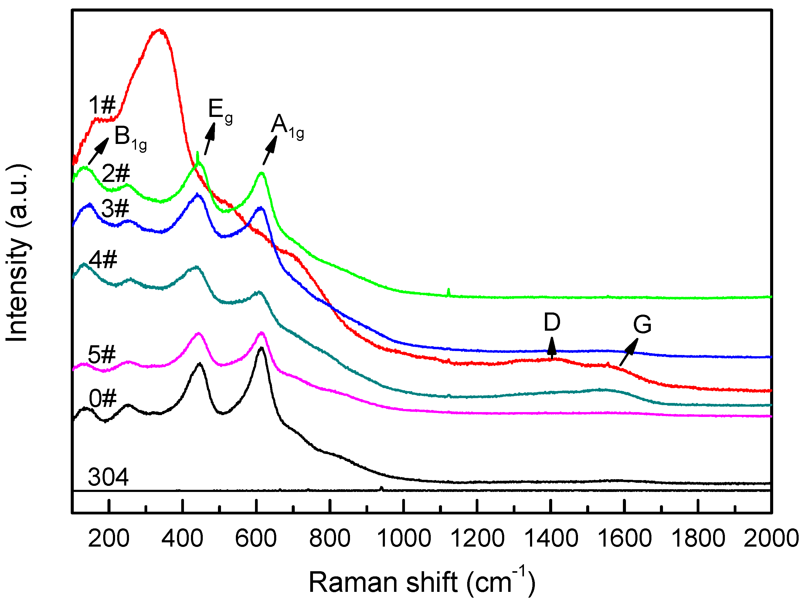
3.1. Raman Spectra

The Raman spectra present in Figure 1 reveal the chemical bonding configurations of the films. The standard Raman wavenumbers of carbon and Ti–O compound are given in Table 2 [41,42]. It can be seen from Figure 1 that in the spectrum of sample 1#, obvious peaks are located at 167.11 cm−1 and 335.39 cm−1, which belong to the characteristic peaks of TiO. The peak of 167.11 cm−1 is caused by the O–Ti–O asymmetrical stretching vibration, while the peak of 335.39 cm−1 is induced by the symmetrical bending of O–Ti–O and the asymmetrical stretching vibration of O–Ti–O.
For the other samples, such as 0#, pronounced Raman peaks located at 144 cm−1, 448 cm−1 and 612 cm−1 can be observed, which are attributed to the B1g, Eg and A1g vibration modes of rutile phase, respectively. The peaks at 144 cm−1 are caused by O–Ti–O bending vibration mode, the peaks at 448 cm−1 belong to the O–Ti–O twisting vibration, and the peak at 612 cm−1 is ascribed to the O–Ti–O axial asymmetric stretching and equatorial bending vibration frequencies. The broader peaks at 239 cm−1 may be caused by the oscillation of the titanium–oxygen bond. Some studies proposed that the oscillation can be induced because of poor order of the lattice structure of rutile or multistage scattering and distortion [41,43].
It is worth noting that two small broad peaks at 1367.86 cm−1 and 1557.86 cm−1, respectively, are surveyed in the Raman spectrum of sample 1#. The two peaks are located in the Raman range of amorphous carbon; specifically, in the D-band at 1340–1400 cm−1 and in the G-band at 1540–1600 cm−1.
According to the Raman results, when CO2 is only used as a reactive gas to supply C and O elements, the synthesized C:Ti–O films consist mainly of TiO phase, and the diamond-like carbon (DLC) structure may also be formed in the C:Ti–O film. In contrast, when the oxygen is introduced as the reactive gas, the Raman vibration modes change into a rutile-like phase structure.

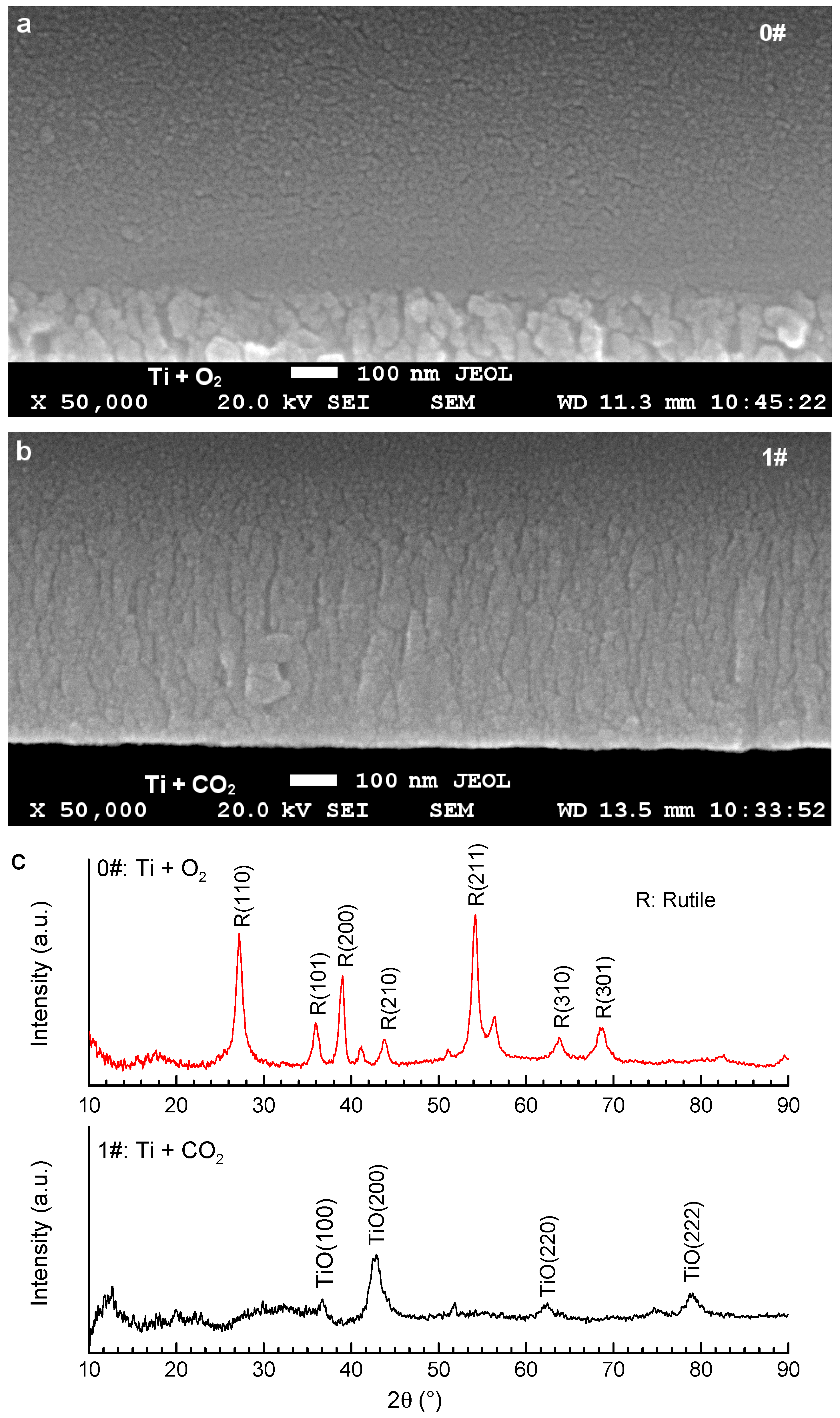
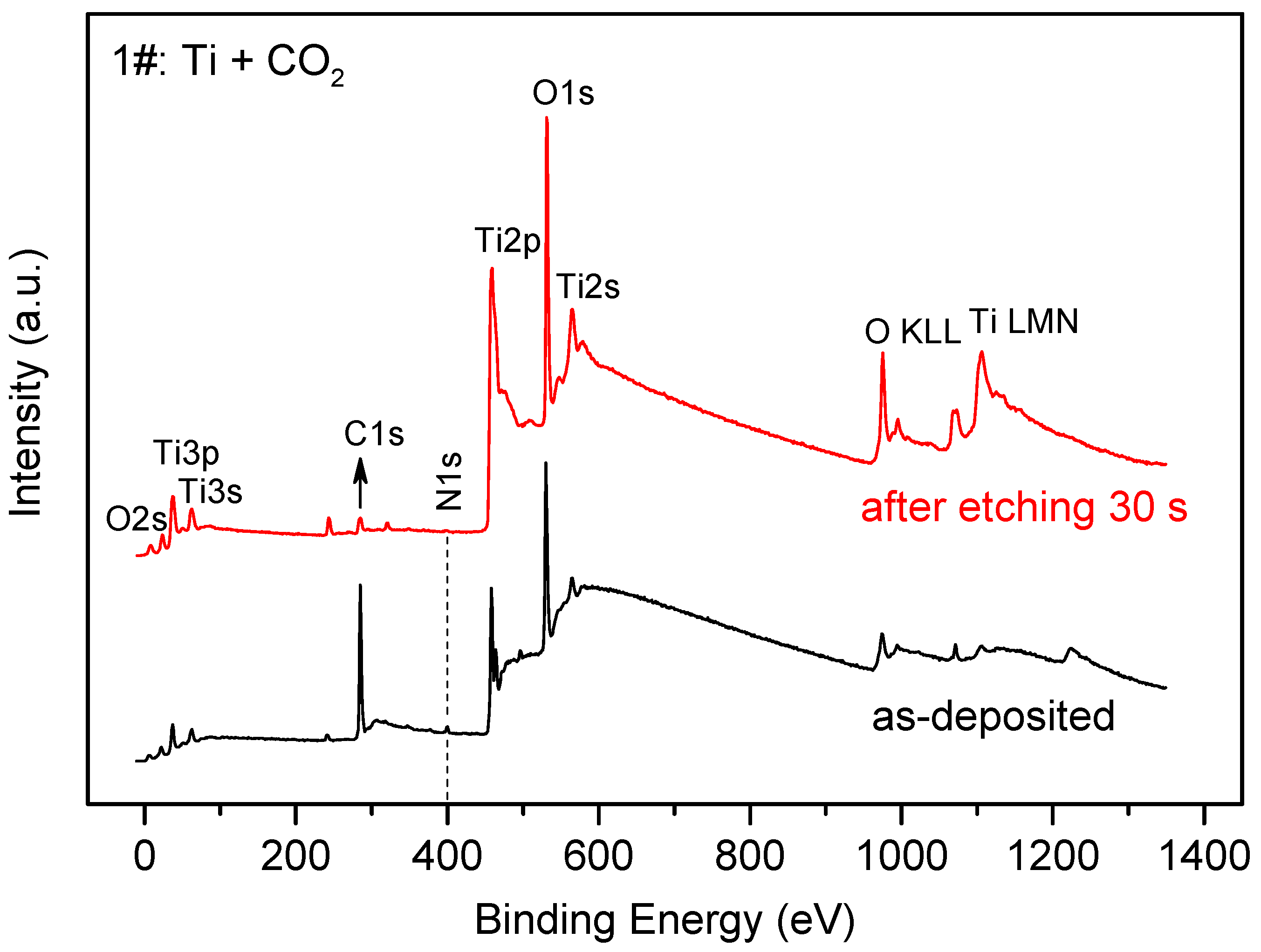
3.2. Structure and Chemistry Composition

Cross-section SEM morphologies are presented in Figure 2a,b to reveal the effect of the type of reactive gas on film growth. The interface of sample 0# shows noticeable granular grains, while that of sample 1# shows obvious columnar grains. This implies that CO2, as a reactive gas, promotes the formation of columnar grains in Ti–O film [44]. It can be inferred that the columnar grains may effectively minimize the recombination of photogenerated carriers caused by grain boundaries because of the decrease in grain boundaries in the direction of the column.
Figure 2c shows the GI-XRD pattern of the as-prepared C-free and C-doped Ti–O films. It is clear that pure rutile phase emerged in the sample 0# that was deposited in only O2 as a reactive gas. However, the sample 1# deposited with only CO2 as a reactive gas consists mainly of TiO phase.
Figure 3 shows the XPS survey spectrum of the C-doped Ti–O film, both as-deposited and after etching for 30 s. A sharp C1s peak is observed in the XPS survey spectrum after etching, which indicates that a detectable quantity of the carbon element has successfully been doped into the Ti–O film.

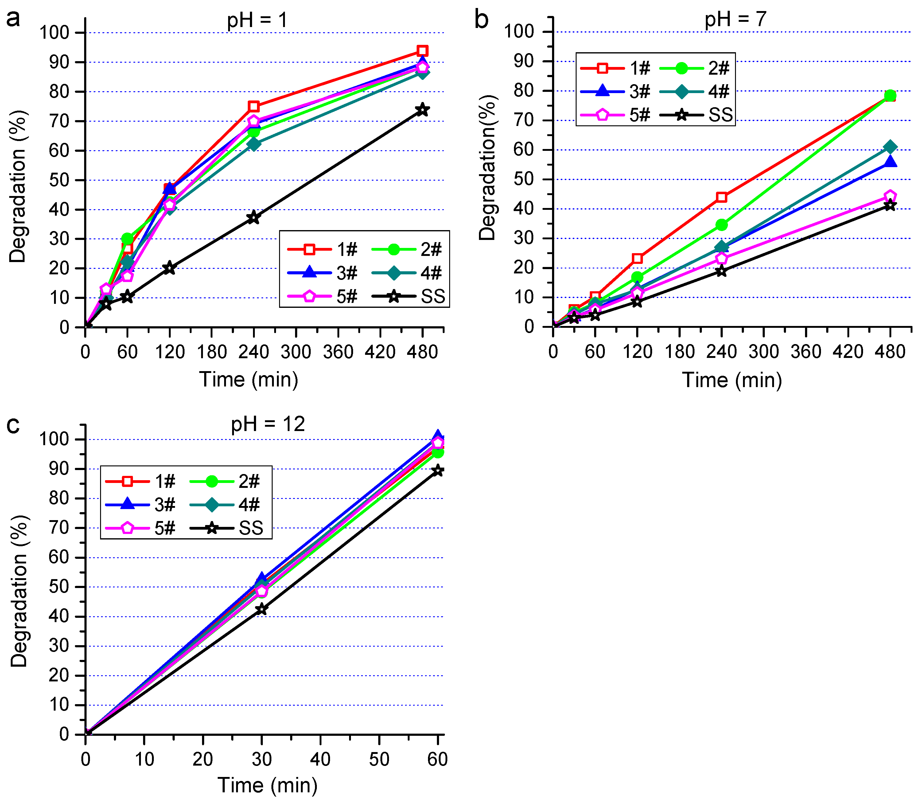
3.3. Photocatalytic Properties

Photocatalytic properties of the C:Ti–O films were scored by the degradation experiment of MO. The degradation rate (D) was calculated with the following equation:
D = C 0 C C 0 × 100 % = A 0 A A 0 × 100 %
where A0 and C0 are the primary concentration and absorbance of MO before the irradiation, while C and A are the concentration and absorbance of MO after a certain irradiation time, respectively [45]. The degradation rate was calculated according to the absorbance change at 464 nm based on the equation (1). To unravel the effect of pH value on MO degradation, acidic (pH = 1) and alkaline (pH = 12) MO solution was prepared by utilizing sulfuric acid or sodium hydroxide to adjust pH value. Figure 4 shows the curves of D vs. irradiation time. A stainless steel (SS) sample without C:Ti–O film was added into the MO solution as reference. It can be seen from Figure 4 that the degradation rates of all as-prepared C:Ti–O films surpassed that of the reference sample SS, which indicates that the as-prepared C:Ti–O films have certain photocatalytic activity.
Note that, after 480 min of UV light irradiation in acid (Figure 4a) and neutral (Figure 4b) environments, the degradation rates of MO by the film 1#, 94% and 78%, respectively, were higher than those obtained with the other C:Ti–O films. In the basic solution (Figure 4c), the C:Ti–O films and SS showed higher degradation rates that reached nearly 100% for all of the C:Ti–O films after only 60 min irradiation, and reached 90% for SS.
Generally, the MO’s degradation can be considered as pseudo-first order of the dynamical reaction according to the following formula:
l n C 0 C = k t
where k is the reactive speed constant, and t is the reaction time. It should be emphasized that all the photocatalytic tests were performed in steady conditions.
Table 3 shows the pseudo first order kinetic model parameters for the degradation of MO. Normally, the pseudo first order kinetic model measures the photocatalytic degradation activity at the interface of the photocatalyst and organic pollutants. The result suggests that the kinetics constants of sample 1# (k = 0.19649) and 2# (k = 0.19822) are far higher than those of sample 3#–5#. The results elucidate that the samples 1# and 2# have higher photocatalytic activity than sample 3#–5#.
The above results can be explained according to the surface energy theory. The interaction between electron donors and acceptors (e.g., the interaction between acids and bases) should be considered to understand the inevitable effect of initial pH value on the photocatalytic degradation. The surface charge properties of Ti–O thin films have a significant influence on the adsorption, migration, and Fermi level position during the reaction, which affects the photocatalytic oxidation process. It has been reported in [46] that TiO2 is an amphoteric oxide, and the isoelectric point (pH-ZPC) pH value is about 6.4. There are TiOH2+, TiOH and TiO functional groups on the surface of hydrated titanium dioxide. The difference in pH value will change the particle surface’s charge property and then exerts a profound influence on the dispersion of the particles in the solution. When the pH value of the solution is close to that of the pH-ZPC, agglomeration easily occurs and larger particles are formed because of Van der Waals force, resulting in the decrease in photocatalytic efficiency [47]. However, when the pH and pH-ZPC are rather different, the agglomeration will not occur because of the repulsive force between the particles, leading to higher photocatalytic efficiency [48,49]. Specifically, when pH > pH-ZPC, the surface of TiO2 is mainly negatively charged TiO, which is beneficial to the migration of holes to the surface, and they can react with H2O and OH adsorbed on the surface to form ∙OH radicals. When pH < pH-ZPc, the surface of TiO2 is mainly positively charged TiOH2+, which is beneficial to the migration of photoelectrons to the surface. TiO2 binds with the adsorbed O2 on the surface to form hydrogen peroxide (H2O2), and further, to form ∙OH, which plays an active role in the combination of electrons and holes. Accordingly, the photocatalytic reaction is promoted, and photocatalytic degradation effect is also enhanced.

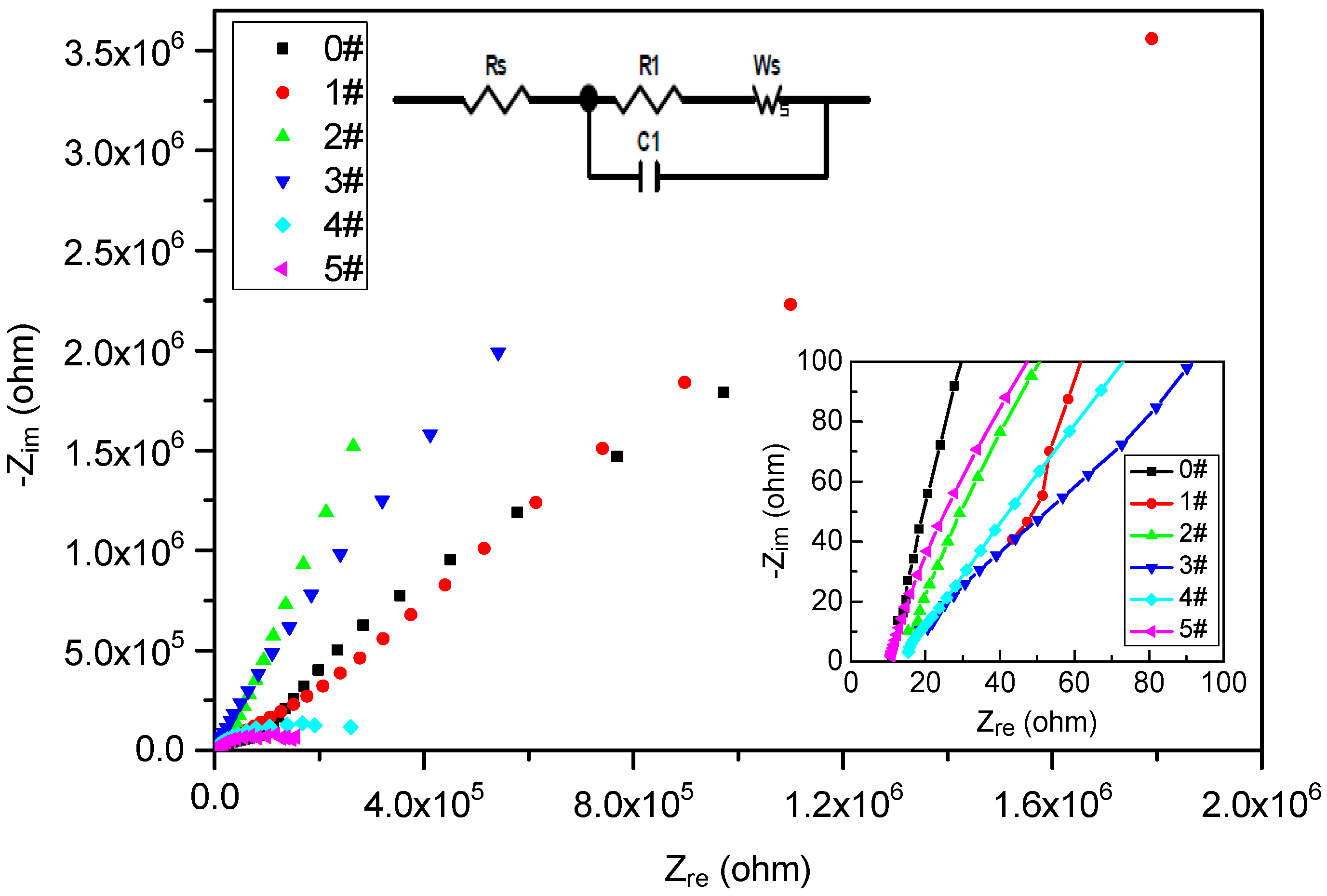
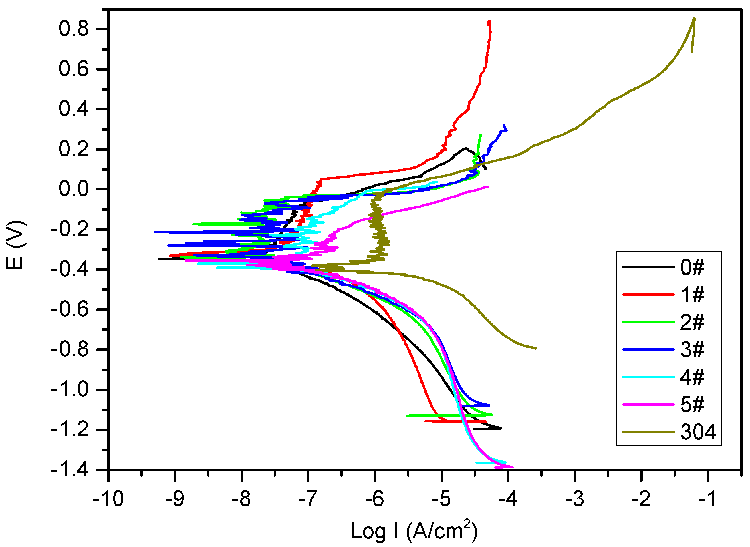
3.4. Corrosion Resistance of the Films

Figure 5 shows the Nyquist EIS diagram of the as-synthesized C:Ti–O films; the inset in the lower right corner is a high-frequency area map. There are arcs in all samples in the high-frequency region. This indicates that the control step is the charge transfer process, and the semi-circle is deformed, which is caused by the inhomogeneity of the film layer or the corrosion products. The appearance of a circular arc indicates that the C:Ti–O film begins to obstruct the charge transfer, and the radius is smaller than that of the sample 0#. This indicates that the electron transfer impedance of the doped carbon film decreases, the radius of sample 3# is the smallest, and the charge transfer resistance is relatively low. The circular arc of the high-frequency section often indicates the charge–discharge process of the double layers, and electron exchange occurs. On the electrode surface, the electrons in the electrode and the ions in the solution will exchange electrons, leading to a redox reaction. The electron exchange resistance of samples 1–5# decreases, indicating that the oxidation-reduction reaction is easier, and the electron transfer rate becomes faster compared to sample 0#. Carbon may act as a surface state in the process of photogenerated carrier transmission, prolonging the lifetime of photogenerated carriers and accelerating their separation. The relative size of the arc radius in the figure can indicate the relative size of charge transfer resistance and can also be used to judge the separation efficiency of the photogenerated electron–hole pairs. The smaller the radius, the faster the separation of charge from the hole. This can explain not only the carrier transport process but also the relationship between photocatalytic activities and the samples.
However, the impedance arc of samples 0–3# in the middle- and low-frequency region produces the approximate linear dispersion effect. The arc in the middle frequency region is related to the charge transfer process on the electrode surface [50,51]. The impedance in this voltage range is mainly caused by electrochemical polarization and is related to the mass transfer and the adsorption process. If both the double layers and charge transfer processes proceed very quickly, the time constants of the processes will differ insignificantly, and the linear impedance spectrum will appear. The low-frequency capacitance–reactance line corresponds to the diffusion of charged ions in the electrode surface layer, which proves that the electrode reaction proceeds at a faster rate and the mass transfer rate of the solution is lower. If the electrode reaction could not meet the fast consumption rate, the diffusion will be inhibited in the electrode reaction process. The occurrence of this phenomenon is closely related to the film on the electrode surface, especially the film porosity, pore size and depth. The approximate linear segment appeared in the samples 0–3#, which indicates that the diffusion path is limited; namely, the diffusion of the reactants during the experiment, i.e., low-valent titanium ions in the C:Ti–O thin film, is limited in solid phase.
The equivalent circuit based on the Nyquist diagram of C:Ti–O films is also shown in the diagram at the top of Figure 5. The RS term is the external series resistance, which accounts for all resistances associated with solution resistance, wires, substrate, or other contacts. R1 is the internal resistance of the film. Ws, representing the change of R1 (caused by carrier diffusion and varies with frequency), is added here. C1 is the interface capacitance.
Figure 6 shows the test result of the polarization curve of the as-synthesized C:Ti–O films. The self-corrosion potentials of samples 0–5# were −0.35 V, −0.32 V, −0.34 V, −0.33 V, −0.37 V and −0.36 V, respectively. The self-corrosion potential of the 304 stainless steel substrates was −0.41 V, which was significantly lower than those of the C:Ti–O films. Self-corrosion potential can reflect the thermodynamic corrosion resistance of the material, indicating that the corrosion probability of the C:Ti–O film-coated samples is lower than that of the pristine SS substrate. The self-corrosion potential of sample 1# is relatively high, indicating that the corrosion probability of sample 1# is minimal under the same conditions.

4. Conclusions

C:Ti–O films were successfully prepared using CO2 as a reactive gas to provide the C element. The cross-sectional microstructure, chemical bonding configurations, photocatalytic property, and corrosion resistance of the as-prepared C:Ti–O films were studied. The results show that (i) the use of CO2 as a reaction gas promotes the formation of a columnar structure. The formation of TiO and DLC phases may be facilitated with only CO2 as a reactive gas. (ii) Compared with C-free Ti–O film, C:Ti–O films have better anti-corrosion properties. (iii) C-doped Ti–O films prolong the lifetime of the photo-induced carrier and reduce the electron exchange resistance. (iv) C:Ti–O films have significant photocatalysis activity and carbon-rich C:Ti–O films further exhibit hyper-photodegradative effect for MO in the alkali environment. Therefore, C:Ti–O films hold promise as an immobilized photocatalyst material.

Author Contributions

Z.W., Writing—review and editing, formal analysis, and funding acquisition; C.Z., Writing—original draft preparation, formal analysis, methodology and data curation; J.L., Writing—review and editing, formal analysis, and methodology; F.W., Writing—original draft preparation, writing—review and editing, project administration and funding acquisition; H.C., Writing—review and editing; Y.P., Writing—review and editing. All authors contributed to the discussion of results and a critical reading of the manuscript. All authors have read and agreed to the published version of the manuscript.

Funding

This work was supported by the Key Projects of Hainan Province (ZDYF2019206), the Natural Science Foundation of Hainan Province (518MS024) and the Natural Science Foundation of China (51461015).

Institutional Review Board Statement

Not applicable.

Informed Consent Statement

Not applicable.

Data Availability Statement

The data presented in this study are available on request from the corresponding author after obtaining permission of the authorized person.

Acknowledgments

We thank D. Xie from Southwest Jiaotong University of China for providing SEM analysis.

Conflicts of Interest

The authors declare no conflict of interest.

References

  1. Zhong, L.; Haghighat, F. Photocatalytic air cleaners and materials technologies—Abilities and limitations. Build. Environ. 2015, 91, 191–203. [Google Scholar] [CrossRef]
  2. Akyol, A.; Yatmaz, H.C.; Bayramoglu, M. Photocatalytic decolorization of Remazol Red RR in aqueous ZnO suspensions. Appl. Catal. B Environ. 2004, 54, 19–24. [Google Scholar] [CrossRef]
  3. Alves, A.C.; Wenger, F.; Ponthiaux, P.; Celis, J.P.; Pinto, A.M.; Rocha, L.A.; Fernandes, J.C.S. Corrosion mechanisms in titanium oxide-based films produced by anodic treatment. Electrochim. Acta 2017, 234, 16–27. [Google Scholar] [CrossRef]
  4. Zangeneh, H.; Zinatizadeh, A.A.L.; Habibi, M.; Akia, M.; Isa, M.H. Photocatalytic oxidation of organic dyes and pollutants in wastewater using different modified titanium dioxides: A comparative review. J. Ind. Eng. Chem. 2015, 26, 1–36. [Google Scholar] [CrossRef]
  5. Mohamed, M.A.; Salleh, W.N.W.; Jaafar, J.J.; Rosmi, M.S.; Hir, Z.A.M.; Abd Mutalib, M.; Ismail, A.F.; Tanemura, M. Carbon as amorphous shell and interstitial dopant in mesoporous rutile TiO2: Bio-template assisted sol-gel synthesis and photocatalytic activity. Appl. Surf. Sci. 2017, 393, 46–59. [Google Scholar] [CrossRef]
  6. Liu, M.; Inde, R.; Nishikawa, M.; Qiu, X.Q.; Atarashi, D.; Sakai, E.; Nosaka, Y.; Hashimoto, K.; Miyauchi, M. Enhanced photoactivity with nanocluster-grafted titanium dioxide photocatalysts. ACS Nano 2014, 8, 7229–7238. [Google Scholar] [CrossRef]
  7. Pelaez, M.; Nolan, N.T.; Pillai, S.C.; Seery, M.K.; Falaras, P.; Kontos, A.G.; Dunlop, P.S.M.; Hamilton, J.W.J.; Byrne, J.A.; O′Shea, K.; et al. A review on the visible light active titanium dioxide photocatalysts for environmental applications. Appl. Catal. B Environ. 2012, 125, 331–349. [Google Scholar] [CrossRef] [Green Version]
  8. Xiang, Q.J.; Yu, J.G.; Wong, P.K. Quantitative characterization of hydroxyl radicals produced by various photocatalysts. J. Colloid Interface Sci. 2011, 357, 163–167. [Google Scholar] [CrossRef]
  9. Li, L.D.; Yan, J.Q.; Wang, T.; Zhao, Z.J.; Zhang, J.; Gong, J.L.; Guan, N.J. Sub-10 nm rutile titanium dioxide nanoparticles for efficient visible-light-driven photocatalytic hydrogen production. Nat. Commun. 2015, 6, 5881. [Google Scholar] [CrossRef] [PubMed] [Green Version]
  10. Xia, T.; Chen, X.B. Revealing the structural properties of hydrogenated black TiO2 nanocrystals. J. Mater. Chem. A 2013, 1, 2983–2989. [Google Scholar] [CrossRef]
  11. Kachina, A.; Puzenat, E.; Ould-Chikh, S.; Geantet, C.; Delichere, P.; Afanasiev, P. A new approach to the preparation of nitrogen-doped titania visible light photocatalyst. Chem. Mater. 2012, 24, 636–642. [Google Scholar] [CrossRef]
  12. Han, C.; Wang, Y.D.; Lei, Y.P.; Wang, B.; Wu, N.; Shi, Q.; Li, Q. In situ synthesis of graphitic-C3N4 nanosheet hybridized N-doped TiO2 nanofibers for efficient photocatalytic H-2 production and degradation. Nano Res. 2015, 8, 1199–1209. [Google Scholar] [CrossRef]
  13. Kumar, S.G.; Devi, L.G. Review on modified TiO2 photocatalysis under UV/visible light: Selected results and related mechanisms on interfacial charge carrier transfer dynamics. J. Phys. Chem. A 2011, 115, 13211–13241. [Google Scholar] [CrossRef]
  14. Zhou, P.; Wu, J.H.; Yu, W.L.; Zhao, G.H.; Fang, G.J.; Cao, S.W. Vectorial doping-promoting charge transfer in anatase TiO2{001} surface. Appl. Surf. Sci. 2014, 319, 167–172. [Google Scholar] [CrossRef]
  15. Qi, K.Z.; Selvaraj, R.; Al Fahdi, T.; Al-Kindy, S.; Kim, Y.; Wang, G.C.; Tai, C.W.; Sillanpaa, M. Enhanced photocatalytic activity of anatase-TiO2 nanoparticles by fullerene modification: A theoretical and experimental study. Appl. Surf. Sci. 2016, 387, 750–758. [Google Scholar] [CrossRef]
  16. Dargahi, Z.; Asgharzadeh, H.; Maleki-Ghaleh, H. Synthesis of Mo-doped TiO2/reduced graphene oxide nanocomposite for photoelectrocatalytic applications. Ceram. Int. 2018, 44, 13015–13023. [Google Scholar] [CrossRef]
  17. Gadow, R.; Kern, F.; Killinger, A. Manufacturing of nanocomposite structural ceramic materials and coatings. Int. J. Mater. Prod. Technol. 2009, 35, 334–345. [Google Scholar] [CrossRef]
  18. Ferrari-Lima, A.M.; de Souza, R.P.; Mendes, S.S.; Marques, R.G.; Gimenes, M.L.; Fernandes-Machado, N.R.C. Photodegradation of benzene, toluene and xylenes under visible light applying N-doped mixed TiO2 and ZnO catalysts. Catal. Today 2015, 241, 40–46. [Google Scholar] [CrossRef]
  19. Park, S.K.; Jeong, J.S.; Yun, T.K.; Bae, J.Y. Preparation of carbon-doped TiO2 and Its application as a photoelectrodes in dye-sensitized solar cells. J. Nanosci. Nanotechnol. 2015, 15, 1529–1532. [Google Scholar] [CrossRef] [PubMed]
  20. Haider, A.J.; Al-Anbari, R.H.; Kadhim, G.R.; Salame, C.T. Exploring potential Environmental applications of TiO2 Nanoparticles. Energy Procedia 2017, 119, 332–345. [Google Scholar] [CrossRef]
  21. Kulathunga, K.M.S.D.B.; Gannoruwa, A.; Bandara, J. Infrared light active photocatalyst for the purification of airborne indoor pollutants. Catal. Commun. 2016, 86, 9–13. [Google Scholar] [CrossRef]
  22. Dawson, M.; Ribeiro, C.; Morelli, M.R. Rutile supported anatase nanostructured films as photocatalysts for the degradation of water contaminants. Ceram. Int. 2016, 42, 808–819. [Google Scholar] [CrossRef]
  23. Zielinska-Jurek, A.; Bielan, Z.; Wysocka, I.; Strychalska, J.; Janczarek, M.; Klimczuk, T. Magnetic semiconductor photocatalysts for the degradation of recalcitrant chemicals from flow back water. J. Environ. Manag. 2017, 195, 157–165. [Google Scholar] [CrossRef]
  24. Koci, K.; Obalova, L.; Matejova, L.; Placha, D.; Lacny, Z.; Jirkovsky, J.; Solcova, O. Effect of TiO2 particle size on the photocatalytic reduction of CO2. Appl. Catal. B Environ. 2009, 89, 494–502. [Google Scholar] [CrossRef]
  25. Hao, W.C.; Zheng, S.K.; Wang, C.; Wang, T.M. Comparison of the photocatalytic activity of TiO2 powder with different particle size. J. Mater. Sci. Lett. 2020, 21, 1627–1629. [Google Scholar] [CrossRef]
  26. Pigeot-Remy, S.; Gregori, D.; Hazime, R.; Herissan, A.; Guillard, C.; Ferronato, C.; Cassaignon, S.; Colbeau-Justin, C.; Durupthy, O. Size and shape effect on the photocatalytic efficiency of TiO2 brookite. J. Mater. Sci. 2019, 54, 1213–1225. [Google Scholar] [CrossRef]
  27. Pellegrino, F.; Pellutie, L.; Sordello, F.; Minero, C.; Ortel, E.; Hodoroaba, V.D.; Maurino, V. Influence of agglomeration and aggregation on the photocatalytic activity of TiO2 nanoparticles. Appl. Catal. B Environ. 2017, 216, 80–87. [Google Scholar] [CrossRef]
  28. Topuz, E.; Traber, J.; Sigg, L.; Talinli, I. Agglomeration of Ag and TiO2 nanoparticles in surface and wastewater: Role of calcium ions and of organic carbon fractions. Environ. Pollut. 2015, 204, 313–323. [Google Scholar] [CrossRef]
  29. Li, G.; Lv, L.; Fan, H.T.; Ma, J.Y.; Li, Y.Q.; Wan, Y.; Zhao, X.S. Effect of the agglomeration of TiO2 nanoparticles on their photocatalytic performance in the aqueous phase. J. Colloid Interface Sci. 2010, 348, 342–347. [Google Scholar] [CrossRef]
  30. Zhou, F.; Ren, X.H. Reversible photochromic photocatalyst Bi2O3/TiO2/Al2O3 with enhanced visible photoactivity: Application toward UDMH degradation in wastewater. J. Environ. Sci. Health Part A 2020, 55, 239–255. [Google Scholar] [CrossRef]
  31. Wang, Z.P.; Liu, Y.; Chen, X.J.; Yu, Q.J. Preparation and characterisation of mesoporous TiO2 photo-catalyst. Environ. Technol. 2006, 27, 1137–1143. [Google Scholar] [CrossRef] [PubMed]
  32. Li, J.X.; Chen, Z.; Fang, J.F.; Yang, Q.; Yang, X.R.; Zhao, W.; Zhou, D.T.; Qian, X.X.; Liu, C.X.; Shao, J.Z. Facile synthesis of TiO2 film on glass for the photocatalytic removal of rhodamine B and tetracycline hydrochloride. Mater. Express 2019, 9, 437–443. [Google Scholar] [CrossRef]
  33. Bozorgtabar, M.; Rahimipour, M.; Salehi, M. Effect of thermal spray processes on anatase-rutile phase transformation in nano-structured TiO2 photo-catalyst coatings. Surf. Eng. 2010, 26, 422–427. [Google Scholar] [CrossRef]
  34. Hamadanian, M.; Behpour, M.; Razavian, A.S.; Jabbari, V. Structural, morphological and photocatalytic characterisations of Ag-coated anatase TiO2 fabricated by the sol-gel dip-coating method. J. Exp. Nanosci. 2013, 8, 901–912. [Google Scholar] [CrossRef] [Green Version]
  35. AlArfaj, E. Investigation of Ag-TiO2 nanostructures photocatalytic properties prepared by modified dip coating method. Philos. Mag. 2016, 96, 1386–1398. [Google Scholar] [CrossRef]
  36. Sajfrtova, M.; Cerhova, M.; Drinek, V.; Danis, S.; Matejova, L. Preparation of nanocrystalline titania thin films by using pure and water-modified supercritical carbon dioxide. J. Supercrit. Fluids 2016, 117, 289–296. [Google Scholar] [CrossRef]
  37. Warkhade, S.K.; Gaikwad, G.S.; Zodape, S.P.; Pratap, U.; Maldhure, A.V.; Wankhade, A.V. Low temperature synthesis of pure anatase carbon doped titanium dioxide: An efficient visible light active photocatalyst. Mater. Sci. Semicond. Process. 2017, 63, 18–24. [Google Scholar] [CrossRef]
  38. Klaysri, R.; Ratova, M.; Praserthdam, P.; Kelly, P.J. Deposition of visible light-active C-Doped titania films via magnetron sputtering using CO2 as a source of carbon. Nanomaterials 2017, 7, 113. [Google Scholar] [CrossRef] [Green Version]
  39. Ratova, M.; Klaysri, R.; Praserthdam, P.; Kelly, P.J. Visible light active photocatalytic C-doped titanium dioxide films deposited via reactive pulsed DC magnetron co-sputtering: Properties and photocatalytic activity. Vacuum 2018, 149, 214–224. [Google Scholar] [CrossRef]
  40. Dang, B.H.Q.; Rahman, M.; MacElroy, D.; Dowling, D.P. Evaluation of microwave plasma oxidation treatments for the fabrication of photoactive un-doped and carbon-doped TiO2 coatings. Surf. Coat. Technol. 2012, 206, 4113–4118. [Google Scholar] [CrossRef]
  41. Xiao, P.; Zheng, S.B.; You, J.L.; Jiang, G.C.; Chen, H.; Zeng, H. Structure and Raman Spectra of titanium oxide. Spectrosc. Spect. Anal. 2007, 27, 936–939. [Google Scholar]
  42. Zheng, R.T.; Cheng, G.A.; Zhao, Y.; Liu, H.P. A Comparative Raman study of carbon nanotubes allays. Spectrosc. Spect. Anal. 2006, 26, 1071–1075. [Google Scholar]
  43. Ma, T.T. Preparation and Enhanced Photocatalytic Performance of Carbon/TiO2 Nanocomposites. Master’s Thesis, Wuhan University of Technology, Wuhan, China, 2011. [Google Scholar]
  44. Amemiya, S. Titanium-oxide photocatalyst. Three Bond Tech. News 2004, 62, 1–8. [Google Scholar]
  45. Ao, C.H.; Lee, S.C. Combination effect of activated carbon with TiO2 for the photodegradation of binary pollutants at typical indoor air level. J. Photochem. Photobiol. A Chem. 2004, 161, 131–140. [Google Scholar] [CrossRef]
  46. Bai, Y.; Sun, H.Q.; Jin, W.Q. Effects of pH values on the physicochemical properties and photocatalytic activities of nitrogen-doped TiO2. J. Inorg. Mater. 2008, 23, 387–392. [Google Scholar] [CrossRef]
  47. Qiu, W.; Ren, C.J.; Gong, M.C.; Hou, Y.Z.; Chen, Y.Q. Structure, surface properties and photocatalytic activity of TiO2 and TiO2/SiO2 catalysts prepared at different pH values. Acta Phys. Chim. Sin. 2011, 27, 1487–1492. [Google Scholar]
  48. Azeez, F.; Al-Hetlani, E.; Arafa, M.; Abdelmonem, Y.; Nazeer, A.A.; Amin, M.O.; Madkour, M. The effect of surface charge on photocatalytic degradation of methylene blue dye using chargeable titania nanoparticles. Sci. Rep. 2018, 8, 7104. [Google Scholar] [CrossRef]
  49. Bano, I.; Kumar, R.V.; Hameed, A. Influence of pH on the preparation of dispersed Ag-TiO2 nanocomposite. Ionics 2012, 18, 307–313. [Google Scholar] [CrossRef]
  50. Gaona-Tiburcio, C.; Montoya-Rangel, M.; Cabral-Miramontes, J.A.; Estupinan-Lopez, F.; Zambrano-Robledo, P.; Cruz, R.O.; Chacon-Nava, J.G.; Baltazar-Zamora, M.A.; Almeraya-Calderon, F. Corrosion resistance of multilayer coatings deposited by PVD on inconel 718 using electrochemical impedance spectroscopy technique. Coatings 2020, 10, 521. [Google Scholar] [CrossRef]
  51. Zhao, X.; Zhuang, Q.C.; Xu, S.D.; Xu, Y.X.; Shi, Y.L.; Zhang, X.X. Investigation of Cr2O3 as anode materials for lithium-ion batteries by electrochemical impedance spectroscopy. J. Electrochem. Soc. 2015, 162, A1156–A1162. [Google Scholar] [CrossRef]
Figure 1. Raman spectra of C-free and C-doped Ti–O films, sample No. are marked in the figure and 304 represents the stainless steel substrate.
Coatings 11 00881 g001
Figure 2. Cross-sectional SEM images of (a) sample 0# (Ti + O2) and (b) sample 1# (Ti + CO2); (c) GI-XRD pattern of the sample 0# and 1#.
Coatings 11 00881 g002
Figure 3. XPS survey spectra of the C-doped Ti–O film (sample 1#): as-prepared and after etching for 30 s.
Coatings 11 00881 g003
Figure 4. The MO solution degradation rates at different pH values—(a) pH = 1, (b) pH = 7 and (c) pH = 12— under irradiation by ultraviolet light.
Coatings 11 00881 g004
Figure 5. Electrochemical impedance Nyquist diagram of synthesized Ti–O films.
Coatings 11 00881 g005
Figure 6. Potentiodynamic polarization curves of C:Ti–O films.
Coatings 11 00881 g006
Table 1. Basic process parameters of reactive magnetron sputtering deposition.
Sample No.CO2 (sccm)O2 (sccm)CO2:O2
0#-6-
1#18--
2#18123:2
3#1863:1
4#1836:1
5#36312:1
Table 2. The standard Raman shifts of carbon and Ti–O compounds.
ItemMat. TypeWavenumber (cm−1)
Ti–OTiO194216332462
Ti2O3199233279325426
Ti3O5155261416606
Rutile144 (B1g)235448 (Eg)612 (A1g)
Anatase147198398515640
CarbonD-band 1340–1400
G-band 1540–1600
Table 3. Pseudo first order kinetic model parameters for degradation of MO (pH = 7) with different Samples.
Target PollutantSample No.k (h−1)kn − kSSR2
Methyl Orange (MO)1#0.196490.128390.98271
2#0.198220.130120.93760
3#0.104810.036710.98278
4#0.120260.052160.95903
5#0.074050.005950.99544
SS0.0681-0.98215
Notes: kn − kSS represents the real decomposition by using the films of C:Ti–O.
Publisher’s Note: MDPI stays neutral with regard to jurisdictional claims in published maps and institutional affiliations.

