
Microstructure and Micro-Hardness of Dissimilar Metal Cladding from a Pipe–Nozzle Mockup for PWR

1
Nuclear Power Institute of China, Chengdu 610213, China
2
CAS Key Laboratory of Nuclear Materials and Safety Assessment, Institute of Metal Research, Chinese Academy of Sciences, Shenyang 110016, China
3
Institute of Corrosion Science and Technology, Guangzhou 510530, China
*
Authors to whom correspondence should be addressed.
Coatings 2022, 12(4), 525; https://0-doi-org.brum.beds.ac.uk/10.3390/coatings12040525
Submission received: 22 March 2022
/
Revised: 8 April 2022
/
Accepted: 11 April 2022
/
Published: 13 April 2022
(This article belongs to the Special Issue Corrosion and Degradation of Materials)
Abstract
:In this study, the dissimilar metal cladding from a pressure vessel pipe–nozzle mockup for PWR was studied using an optical microscope, scanning electron microscopy, energy-dispersive X-ray spectrometry, electron back-scattering diffraction, and micro-hardness measurement. The microstructure of the SA508 side is non-uniform along the fusion boundary, especially at the concave and convex areas. Martensitic layer (type I and type II) boundaries are found at the fusion boundary area. The chemical composition, residual strain, and microstructure across the SA508–309L fusion boundary are very complex and hence result in a complicated micro-hardness distribution.
1. Introduction
SA508, one kind of low-alloy steel, is usually utilized for the fabrication of pressure vessels and pipe–nozzles in a pressurized water reactor (PWR) nuclear power plant due to its relatively low cost and high strength [1,2]. However, its corrosion resistance is very low when it is directly exposed to the high-temperature pressurized primary water in a PWR. As a result, a stainless steel cladding layer with a high corrosion resistance is necessary to protect the SA508 low-alloy steel, acting as a barrier layer [3]. As the chemical composition, mechanical properties, and microstructure of low-alloy steel are significantly different from stainless steel (filler metal), the microstructure of the dissimilar metal cladding, especially at the interfacial area, should be very complex. Hence, many problems arise during the cladding process, including sharp changes in element distribution, mechanical property, and microstructure across the fusion boundary; carbon migration; weld residual stress–strain; and the formation of special boundaries at the fusion boundary area [4,5,6,7].
In light of the above problems, the dissimilar metal cladding area usually becomes the weak point of the pipe–nozzle. In fact, many stress corrosion cracking (SCC) failures have occurred at this kind of dissimilar metal welding area [8,9]. As a result, lots of research on the microstructure and service behavior of this area has been published. Our group has worked on dissimilar metal weld joints (DMWJs) in PWR nuclear power plants for more than ten years and has investigated different kinds of DMWJs with different filler metals, base metals, welding methods, and welding parameters [10,11,12,13,14,15]. Even though the microstructures of an SA508–309L/308L–316L domestic dissimilar metal weld safe-end joint and the low-alloy SA508–309/308L stainless steel dissimilar metal weld for pressure vessel lining have been studied previously [1,16], the dissimilar metal cladding of the inner pipe–nozzle has not been investigated in detail before.
During the fabrication of the nuclear power plant, the pipe–nozzle is welded to the primary loop, forming the safe-end DMWJ. In one previous failure case, the SCC crack from the surface of the cladding, propagated to the fusion boundary of the dissimilar metal cladding, then grew just along the fusion boundary of the safe-end DMWJ, leading to a primary water leakage [8]. In fact, SCC is the main failure mode of DMWJ in nuclear power plants [5,17]. SCC behavior is related to the material, stress, and environment. When the stress and environment (which refers to the water chemistry of the primary water in a PWR) are well controlled, the material becomes the key factor affecting SCC. Consequently, there is a requirement to understand and control the microstructure of the DMWJ. Since the microstructure at the weld interface area and the heat-affected zone (HAZ) is highly dependent on the welding parameters, it is necessary to characterize the microstructure and the basic mechanical properties to guide the optimization of the welding parameters. This is equally applicable to dissimilar metal cladding.
2. Materials and Experiment
2.1. Materials
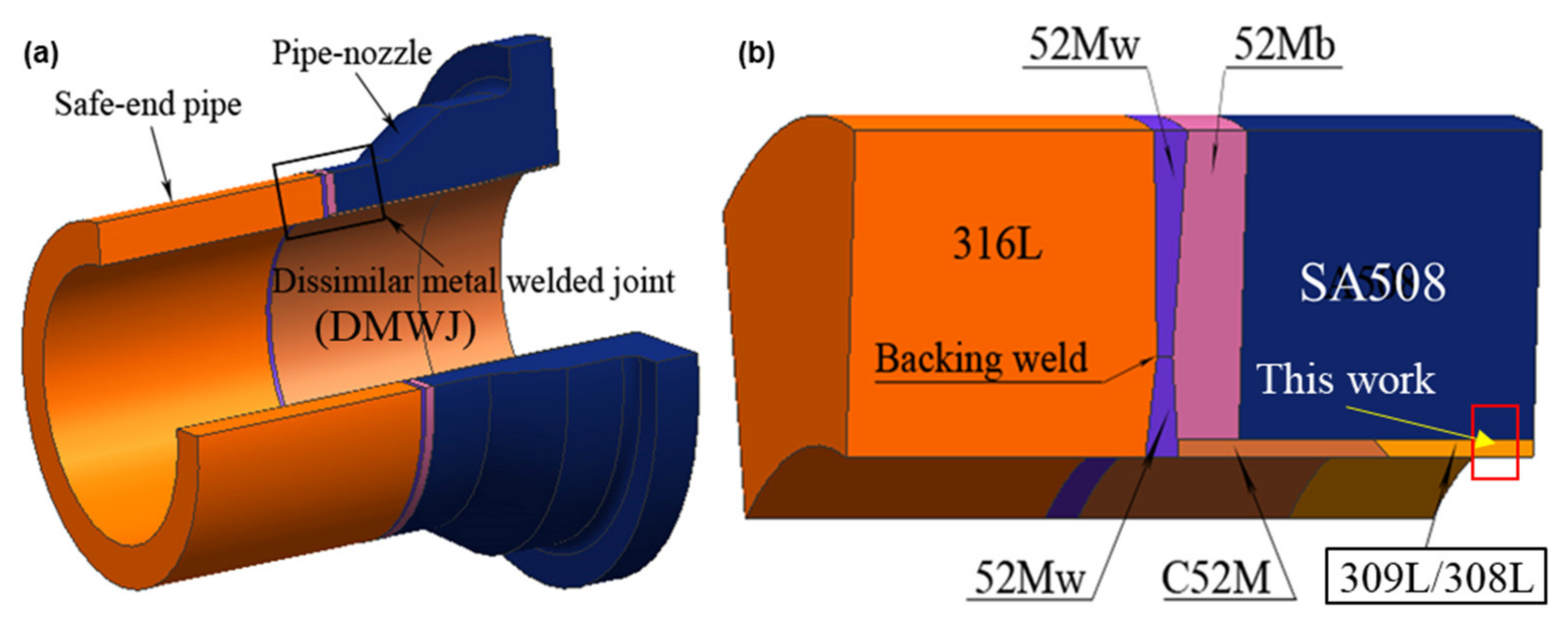
The dissimilar metal cladding samples observed in this study were cut from the inner surface of a pipe–nozzle formed by SA 508 (Gr.3) low-alloy steel. The cladding materials were 309L and 308L stainless steel. A schematic diagram of the pipe–nozzle, the safe-end pipe, the DMWJ, and the exact position of the dissimilar metal cladding investigated in this study is presented in Figure 1 [18]. Comparable dissimilar metal welds have been studied before; however, the welding parameters are different [1,16]. The chemical compositions of SA508 and the filler metals are listed in Table 1. Submerged arc welding (SAW) was used for the cladding, in which 309L was prepared as the first layer and 308L as the second and third layers. The welding parameters are presented in Table 2. The current range was 760–800 A, the voltage was well controlled at 27.5 V, and the welding speed was 150 mm/min. The SA508 base metal was preheated to 150–180 °C before welding, and the inter-pass temperature was controlled between 161 and 197 °C. The cladding surface was machined to achieve the final size requirement.
2.2. Microstructure Characterization
Firstly, the samples were ground using silicon carbide abrasive paper with grit sizes ranging from 120# to 2000#, and then mechanically polished with 2.5 μm polishing pastes at a speed of 800 rpm. When no scratches were visible on the polished surfaces, the samples were etched for optical microscope (OM, Axio Observer Z1, Zeiss, Oberkochen, Germany) observation. For the SA508 base metal and its HAZ, a 4% nital solution was used for a duration of 5–10 s, while the weld metal was electro-etched in a 10% oxalic acid+ 90% H2O solution.
A scanning electron microscopy with X-ray microanalysis (SEM/EDS, FEI XL30, Hillsboro, OR, USA) was used to investigate the chemical composition distribution across the fusion boundary, at an accelerating voltage of 20 kV. Before the EDS line scanning, the sample was slightly etched using the 4% nital solution for a duration of 3–5 s to obtain the position of the fusion boundary.
Electron back-scattering diffraction (EBSD, Oxford, UK) was used to study the grain size and residual strain distribution across the fusion boundary. The EBSD scanning voltage was 25 kV at a scanning step size of 0.5 μm. The raw data were then analyzed using the orientation imaging microscopy (OIM) software. The process to prepare the sample for an EBSD observation has been described in detail previously [1].
2.3. Micro-Hardness Test
The micro-hardness test was performed using an MHVD-1000AP micro-hardness tester (Shanghai, China) at a load of 0.98 N and a holding time of 15 s. Before testing, the sample was also slightly etched to show the fusion boundary.
3. Results and Discussion
3.1. Microstructure by OM
3.1.1. OM Microstructure of Base Metal and Weld Metals
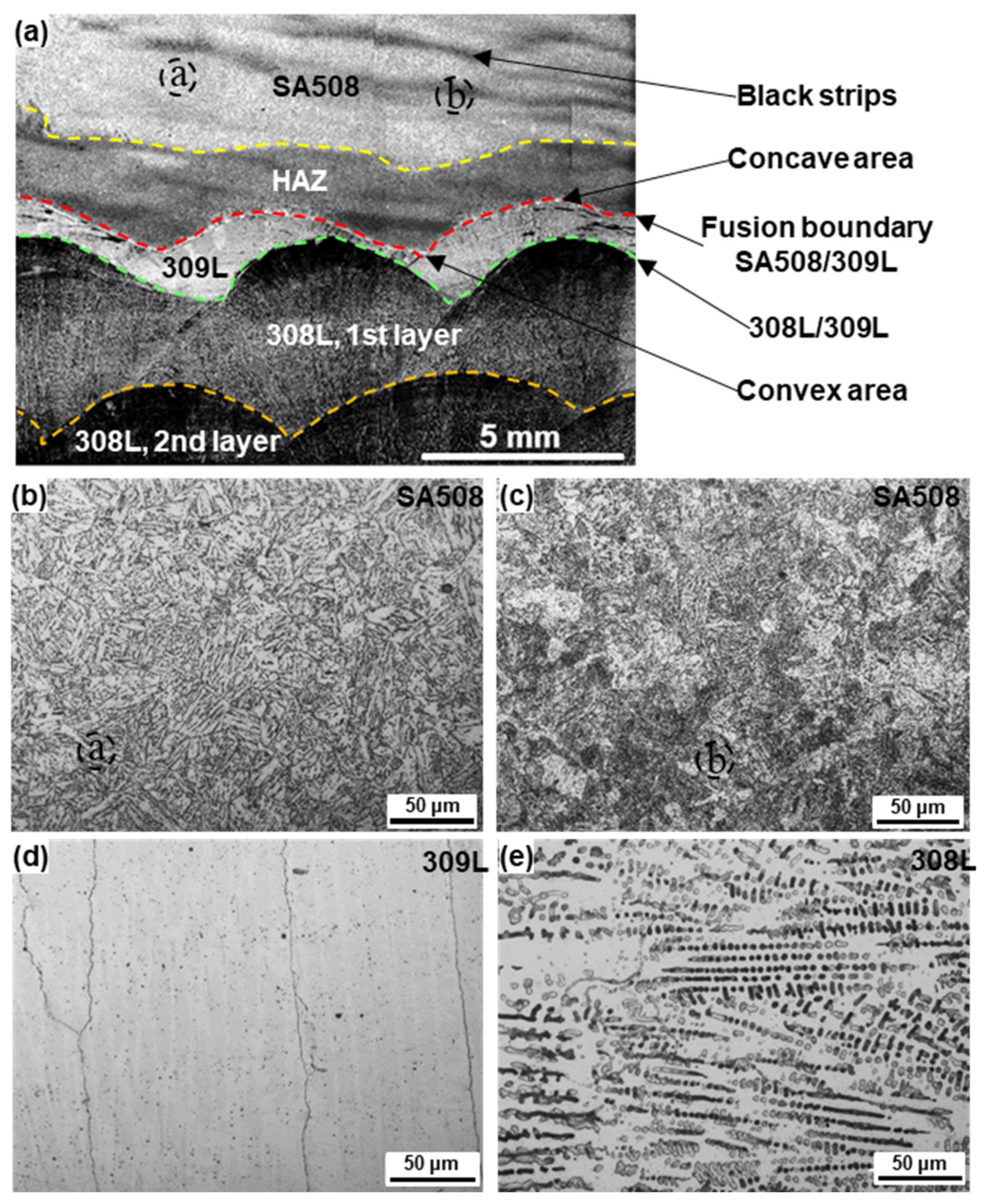
The OM image at a low magnification detailing both the base metal and the weld metal is shown in Figure 2a. The base metal and its HAZ, the first cladding layer (309L), and the 308L cladding layers (the second and third layers) are significantly distinct due to their different microstructures. In addition, the fusion boundary (or the interface) is wavelike.
The microstructure in the SA508 base metal is not uniform; it contains many “black strips” along the axial direction of the pipe–nozzle (Figure 2a). The microstructure of the normal area is shown in Figure 2b, suggesting the presence of a bainite microstructure which was composed of ferrite laths and inter-lath carbides. Figure 2c shows the microstructure of the black strip area. More carbides were found in these areas and they were more uniformly distributed than in the normal area, not only at the boundaries of the ferrite laths but also within the ferrite laths. As these strips are far from the fusion boundary, they may result from macro-segregation during the manufacturing process rather than the welding process.
Figure 2d shows the microstructure of the 309L weld metal. An almost fully austenite structure was found, which was different from the normal microstructure that consists of coarse grains of dendrite-like austenitic structure and ferrites between the dendrites, as demonstrated in Figure 3a of Reference [1]. As described in Reference [19], the solidification mode of the weld metal was determined by the chemical compositions, Creq and Nieq, where the Creq = Cr% + Mo% + 1.5 Si% + 0.5 Nb% and the Nieq = Ni% + 30 C% + 0.5 Mn%. The chemical composition of the 309L layer should deviate from its original composition due to the dilution effect of the melted SA508. On the other hand, the dilution phenomenon had a greater effect on Nieq than Creq as the coefficient factor for C was 30. As a result, the diffusion of carbon from the SA508 to the 309L layer led to a significant increase in the value of Nieq. When the ratio of Nieq to Creq is high enough, the microstructure of 309L should be fully austenite. The microstructure of the 308L was dendrite-like austenite with dot and rod ferrites between these dendrites (Figure 2e).
3.1.2. OM Microstructure across Fusion Boundary
Since the etching methods for SA508 and the weld metal were different, the detailed microstructures across the fusion boundary were observed separately. The microstructures of the 309L side and the SA508 side are shown in Figure 3 and Figure 4, respectively.
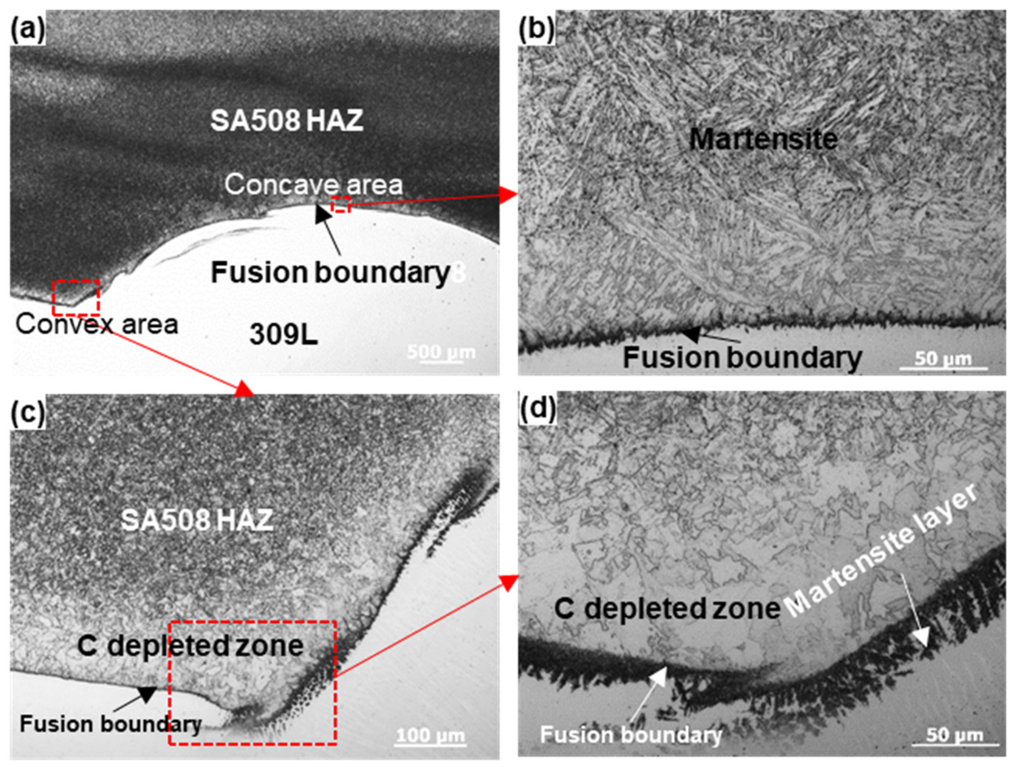
It is obvious that the microstructure of the SA508 side was not uniform along the fusion boundary, as the heat flux was not homogeneous for every bead or for multi-bead welding (Figure 4a). Overall, a light layer of carbon depletion in the HAZ just adjacent to the fusion boundary was found, although its width was not uniform, which was caused by carbon diffusion from SA508 to 309L. The microstructure of the concave area near the fusion boundary was coarse martensite (Figure 4b), and the average width of the carbon-depleted zone in this area was about 80 μm. A thin dark layer was observed along the fusion boundary, which was shown to be martensite in Reference [4]. In addition, carbides were found at this area, formed by the reaction of the migrated carbon from SA508 with the chromium in 309L. The microstructure of the convex area is shown in Figure 4c,d, where ferrite was the main structure in the carbon-depleted zone. Furthermore, the carbon-depleted zone in this area was larger, at an average width of about 120 μm, and more obvious than the zone in the concave area. This kind of phenomenon had also been observed in our previous study [1]. Carbon migration is related to the temperature and the high-temperature duration of the welding process [11]. The convex area was double-heated during the multi-bead welding process, and its interface for carbon migration was longer, which promoted carbon migration during welding. A martensite layer was also found in this area, and its thickness was also greater than the layer in the concave area, as its formation was linked to the more pronounced carbon migration in the convex area.
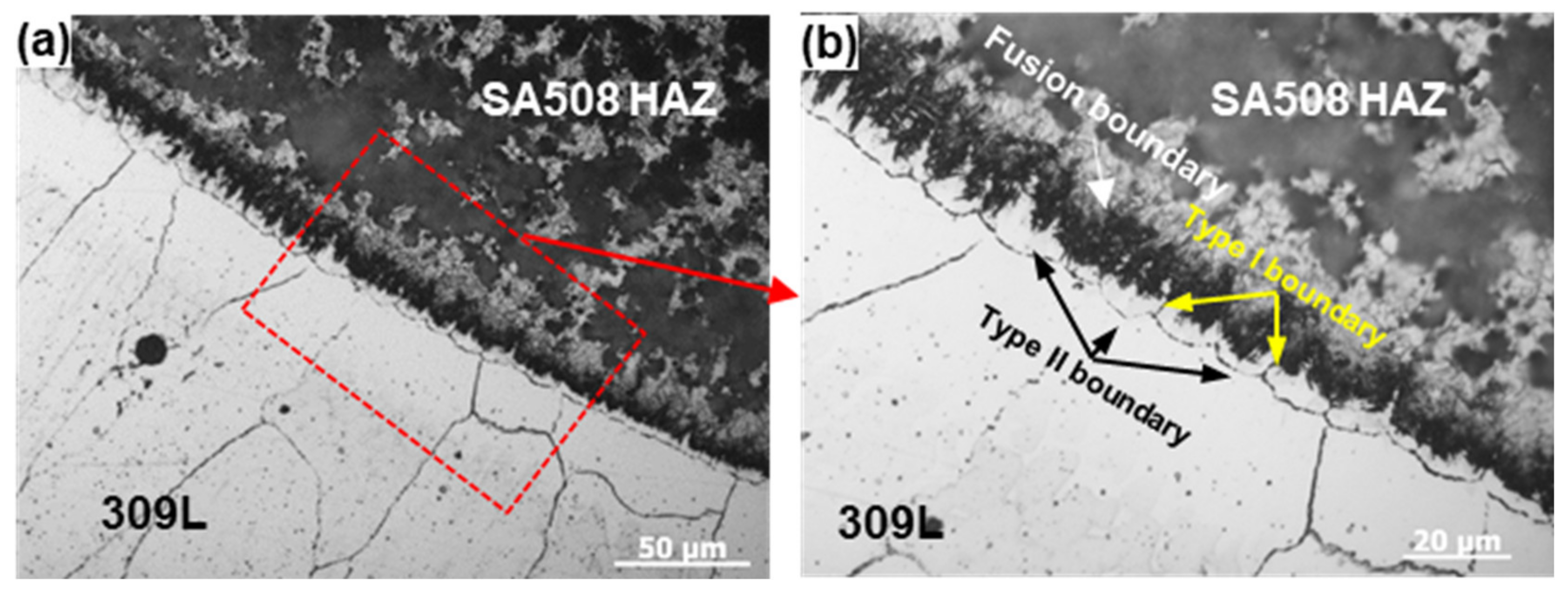
On the 309L side, the most obvious feature was the formation of the type I and type II boundaries (Figure 3). A type II boundary refers to the grain boundary that is parallel to the fusion boundary, while a type I boundary connects the fusion boundary with the type II boundary [20,21]. Although these boundaries are usually found in dissimilar metal (metals with different microstructure) weld joints [22], some researchers have demonstrated that they can also be found at the 316L-182 fusion boundary area since they have the same structure (austenite) [23]. The formation mechanism of these boundaries was described in detail in our previous publications [10,14]. In addition, these boundaries were usually high-angle boundaries and were easy to mechanically crack during the three-points bending test [11]. As a result, they were hazardous to the SCC resistance of the fusion boundary area.
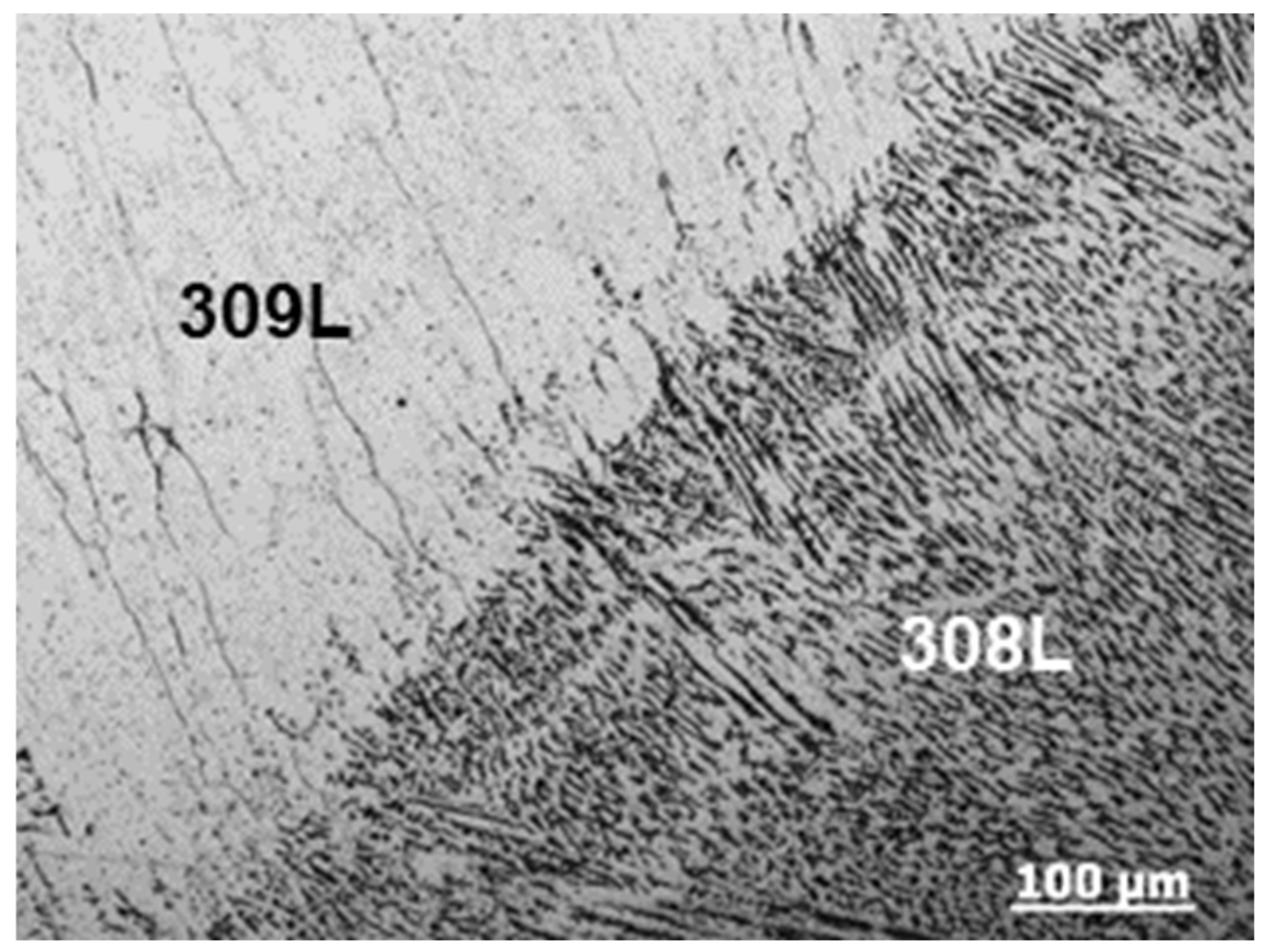
Figure 5 shows the microstructure at the 309L–308L interface. Again, more ferrites were found in 308L than in 309L. In addition, epitaxial growth was observed at the interface area as 309L and 308L have similar crystal structure and chemical composition. This phenomenon was also observed at the 308L and 316L fusion boundary area and was verified using EBSD [1].
3.1.3. OM Microstructure of SA508 HAZ
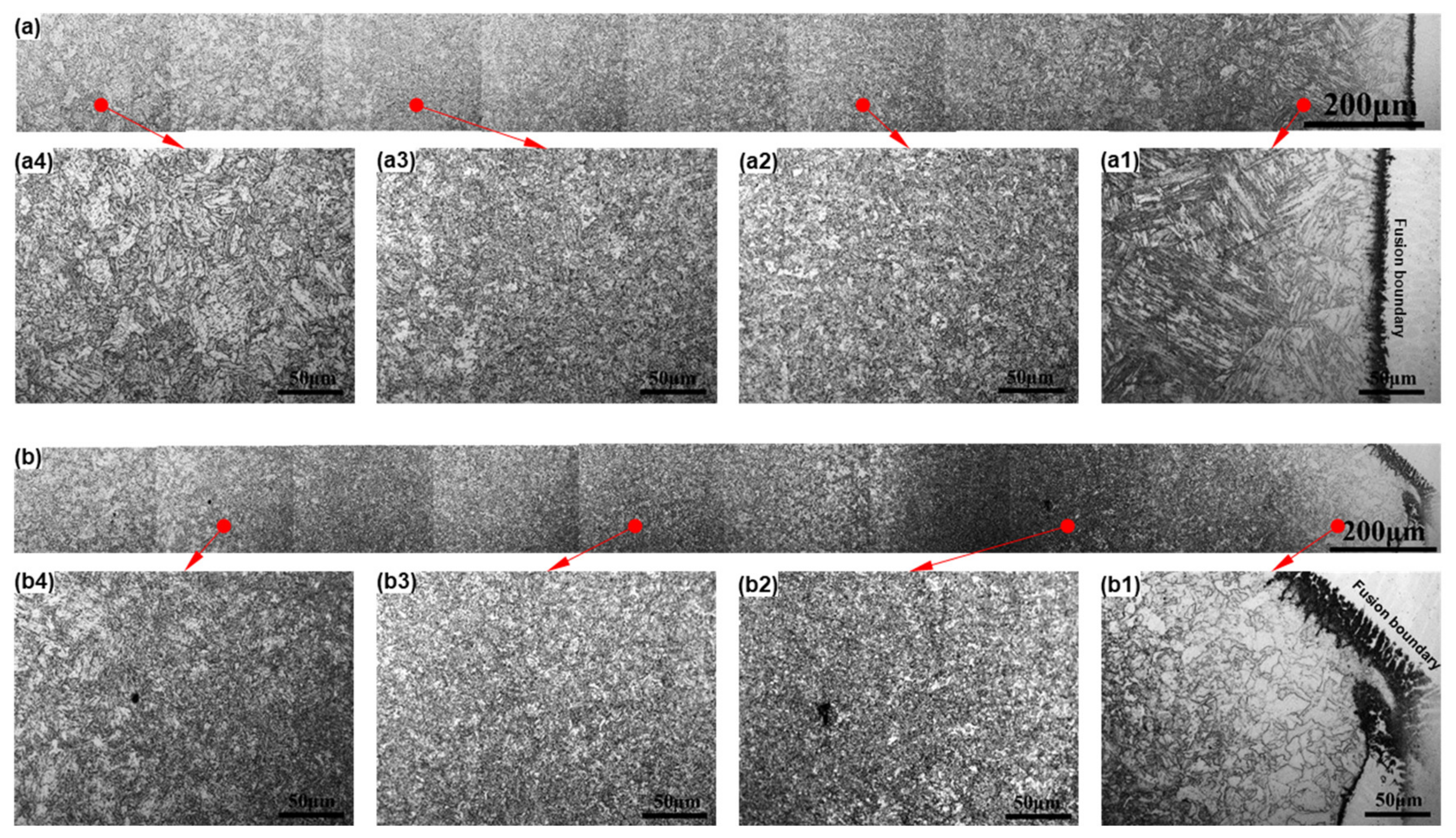
As the heat flux during the welding process changed from the fusion boundary to the SA508 base metal, HAZs with widths ranging from 2 mm to 3 mm and a microstructure transition formed, as shown in Figure 6. Microstructure transitions from the fusion boundary at both the concave area (Figure 6a) and at the convex area (Figure 6b) are given in Figure 6. Figure 6a1–a4 demonstrate higher magnifications of the typical areas in Figure 6a. From the fusion boundary, the microstructure transition was coarse martensite + carbide (Figure 6a1) → small amounts of granular bainite + fine martensite (Figure 6a2) → bainite + small amounts of fine martensite (Figure 6a3) → bainite (base metal, Figure 6a4), which is consistent with the findings in Reference [1]. However, the microstructure transition at the convex area was somewhat different due to the presence of the “black strips” (Figure 2) in the original base metal. In fact, microstructure change also occurred in the “black strips” area under the thermal cycles during cladding. From the fusion boundary to the base metal in Figure 6b, the microstructure transition was ferrite (Figure 6b1) → small amounts of granular bainite + fine martensite (Figure 6b2) → bainite + small amounts of fine martensite (Figure 6b3) → bainite (base metal, Figure 6b4). Although the microstructure was similar in Figure 6a2,b2, the grain size was different. The formation of these “black strips” resulted in a smaller grain size in Figure 6b2.
3.2. Chemical Compositions across the Fusion Boundary
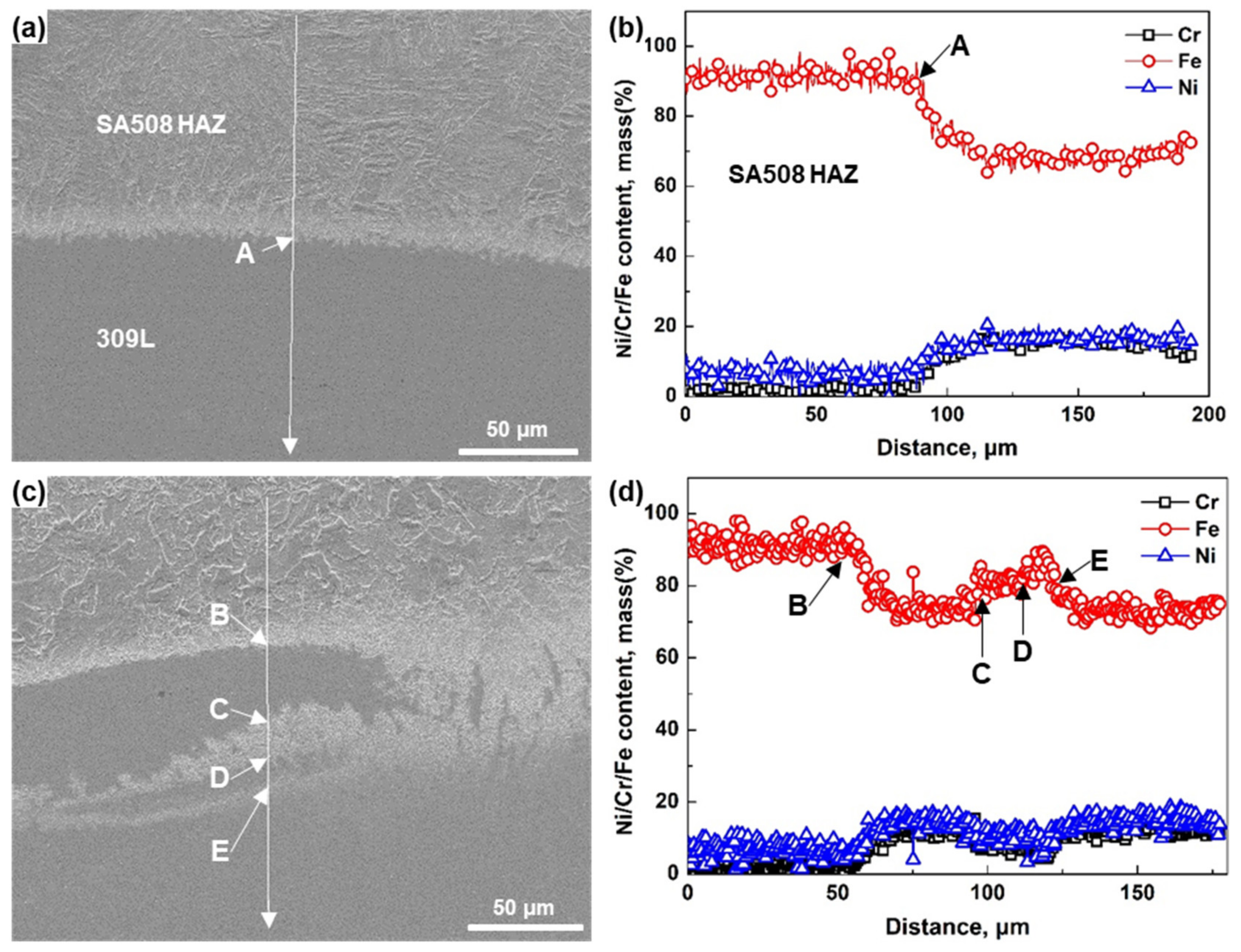
The chemical composition distributions across the SA508–309L fusion boundary were characterized using EDS line scanning, and the results are shown in Figure 7. Since the microstructure of the concave area was different from the convex area, the chemical composition distributions were measured separately. Figure 7a,b display the results at the concave area, showing that the SA508 had a higher content of Fe but lower contents of Cr and Ni. In addition, though a dramatic change was found across the fusion boundary, a thin diluted area with a width of about 30 μm was observed.
However, the chemical composition change at the convex area was much more complex than at the concave area (Figure 7c,d). From point B to point C, the chemical composition was similar to the one in Figure 7a, while the chemical transition zone was only about 15 μm in width. The area between points C and D, with the chemical composition between SA508 and 309L, was the martensite area in Figure 4d. An unmixed zone (point C to point D) with a similar chemical composition to the base metal was also found. The reasons for the formation of the unmixed zone have also been described in previous work [1].
3.3. Microstructure by EBSD
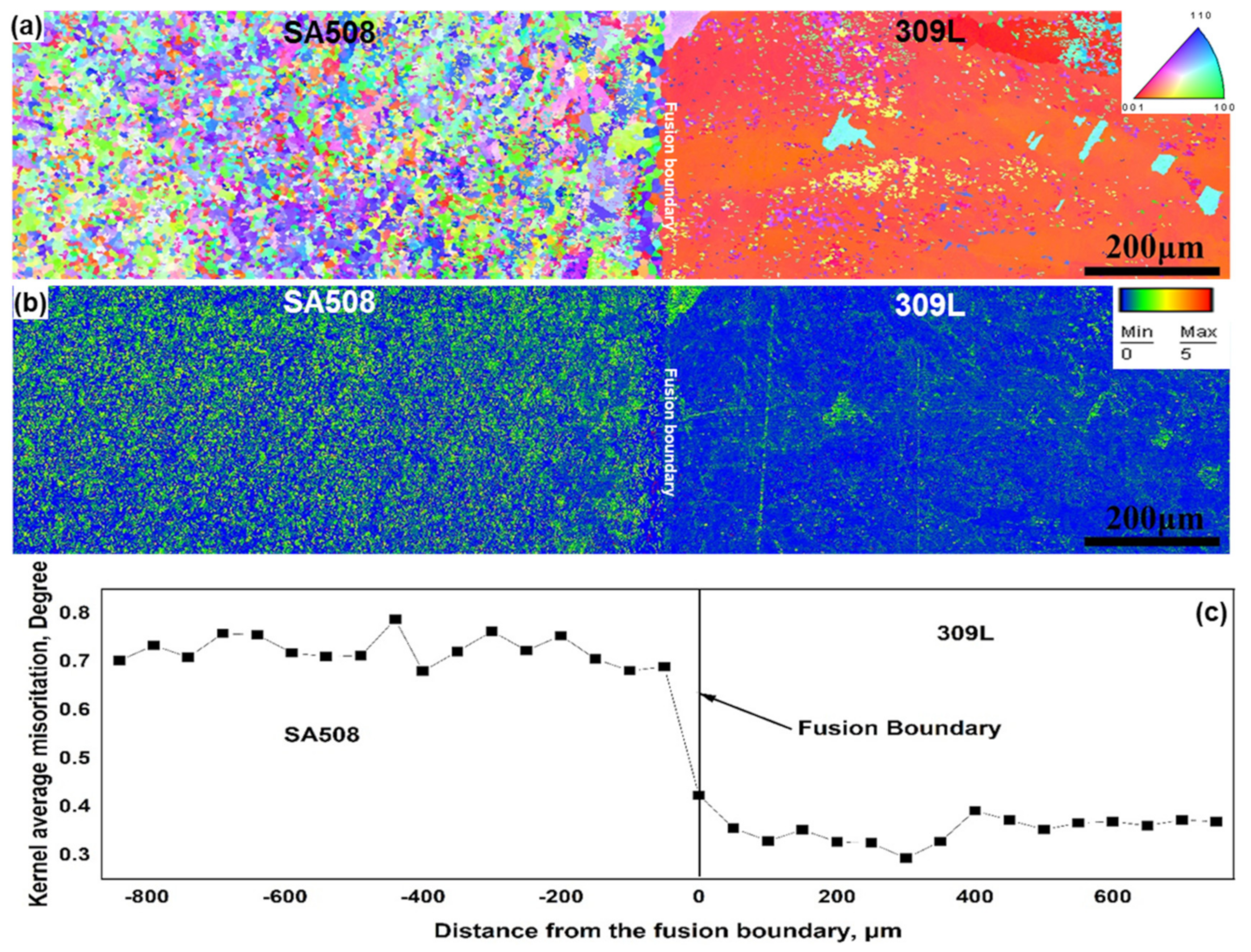
The EBSD result of the SA508–309L interface area is shown in Figure 8, including the inverse pole figure (IPF) in Figure 8a, and the kernel average misorientation (KAM) distribution map in Figure 8b,c. From the IPF figure, the grain size from the fusion boundary to the base metal was very similar to the results in Figure 6. However, no type I or type II boundaries were found at this area, indicating that not all of the fusion boundary areas had these kinds of special boundaries. Usually, the KAM is used to estimate the residual strain in materials, that is, the higher the KAM value, the more severe the residual strain [24,25,26,27]. From Figure 8b, we can see that the residual strain in SA508 was higher than in 309L cladding. In addition, the residual strains in both materials were nearly homogeneous, with very low fluctuation.
3.4. Micro-Hardness Distribution
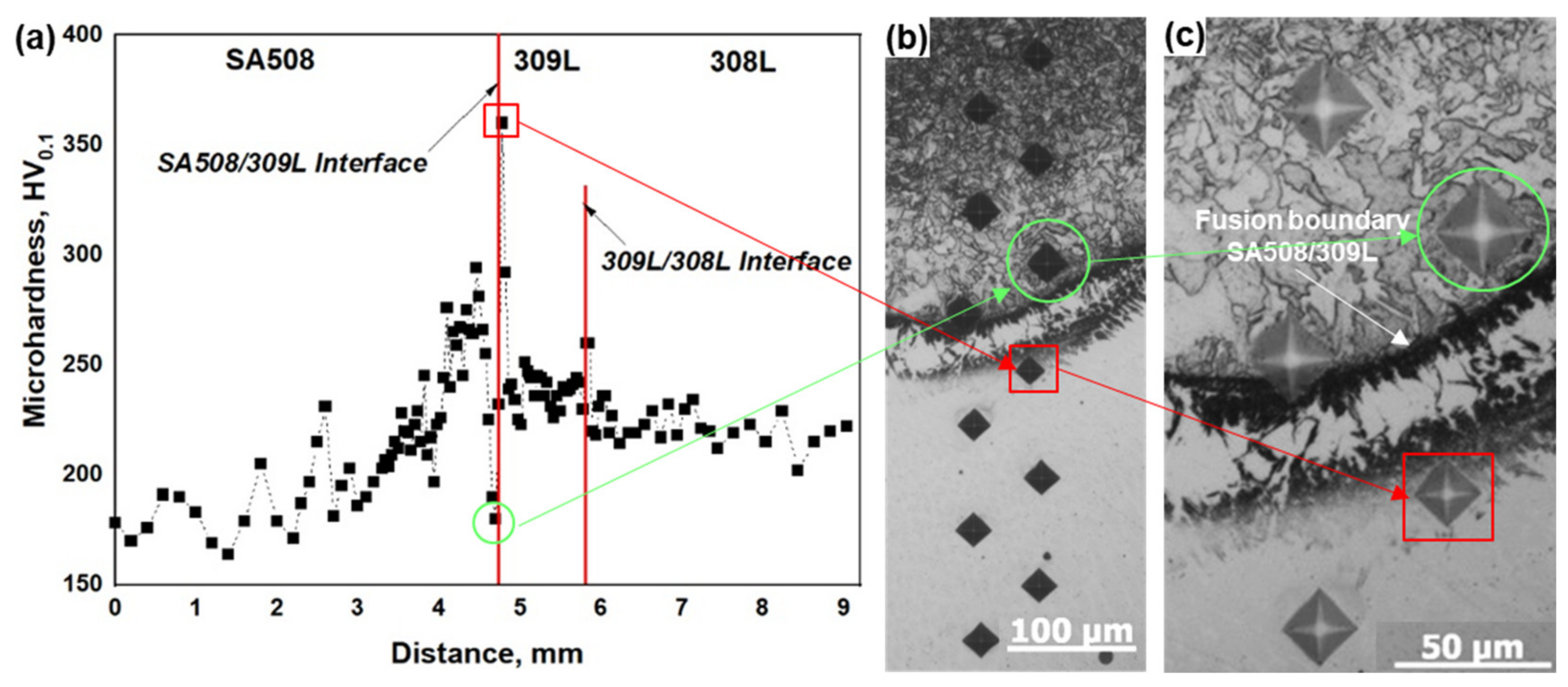
The micro-hardness distribution from the SA508 base metal to the 309L cladding layer and then to the 308L layers is shown in Figure 9a, and the images of the indentations at the SA508–309L interface area are shown in Figure 9b,c, as there was a dramatic change in micro-hardness at the interface area.
In Figure 9a, the micro-hardness of the SA508 base metal was measured to be about 175 HV, which then increased as it moved to the SA508–309L interface. In addition, two obvious fluctuations in hardness were found at the positions of 1.8 mm and 2.5 mm (abscissa axis). This may have resulted from the harder “black strips” areas in the base metal, as these areas had more carbides and their widths were similar to the widths of the fluctuations in the curve. The greater hardness of the HAZ was caused by the formation of martensite and the grain size being finer than in the base metal, as noted by both the OM and EBSD observations. However, a dramatic change was found adjacent to the fusion boundary due to the carbon migration which occurred during the cladding process. The hardness of the carbon-depleted zone was only ~170 HV, while it was ~360 HV for the martensitic layer. Furthermore, the hardness of the 309L just adjacent to the interface was higher (~290 HV) than the normal 309L (~240 HV), and this may have also been caused by the carbon migration. The overall hardness of the 309L was about ~15 HV higher than that of the 308L. The hardness of the 309L–308L interface area was greater than both the weld materials as this area usually had greater residual strain.
4. Conclusions
The microstructure and micro-hardness of some dissimilar metal cladding from a pressure vessel pipe–nozzle for PWR nuclear power plants were studied in detail using the characterization of OM, SEM, EDS, and EBSD, and the measurement of micro-hardness, and the following conclusions can be drawn:
- (1)
- The SA508 base metal has a bainite microstructure and black strip area with more carbides. The 309L cladding has an almost fully austenite structure, while the microstructure of the 308L layers is dendrite-like austenite with dot and rod ferrites between the dendrites.
- (2)
- The microstructure on the SA508 side is not uniform along the fusion boundary. At the concave area, coarse martensite just adjacent to the fusion boundary and a thinner carbon-depleted zone are found. At the convex area, ferrite is the main structure in the carbon-depleted zone and the carbon-depleted area is wider and more obvious than that of the concave area.
- (3)
- A martensitic layer, with type I and type II boundaries, is found at the SA508–309L fusion boundary area. In addition, a microstructure transition with a width of 2–3 mm is observed in the SA508 HAZ.
- (4)
- The chemical composition, residual strain, and micro-hardness distributions across the SA508–309L fusion boundary are very complex. The local hardness is highly dependent on the microstructure and element distribution.
Author Contributions
Conceptualization, J.W. (Jiazhen Wang) and H.M.; methodology, J.W. (Jiazhen Wang); validation, J.C., H.M. and Z.Z.; investigation, J.W. (Jiazhen Wang); resources, J.W. (Jiazhen Wang); data curation, J.W. (Jiazhen Wang); writing—original draft preparation, J.W. (Jiazhen Wang); writing—review and editing, H.M.; visualization, Z.Z.; supervision, J.W. (Jianqiu Wang); project administration, H.M.; funding acquisition, J.W. (Jianqiu Wang). All authors have read and agreed to the published version of the manuscript.
Funding
This work is jointly supported by Youth Innovation Promotion Association CAS (2022187), Hundred Talent Project (E155F207), and Opening project fund of Materials Service Safety Assessment Facilities (MSAF-2021-003).
Institutional Review Board Statement
Not applicable.
Informed Consent Statement
Not applicable.
Data Availability Statement
Data sharing is not applicable to this article.
Conflicts of Interest
The authors declare no conflict of interest.
References
- Ming, H.; Zhang, Z.; Wang, J.; Han, E.-H.; Ke, W. Microstructural characterization of an SA508–309L/308L–316L domestic dissimilar metal welded safe-end joint. Mater. Charact. 2014, 97, 101–115. [Google Scholar] [CrossRef]
- Wang, H.T.; Wang, G.Z.; Xuan, F.Z.; Liu, C.J.; Tu, S.T. Local mechanical properties of a dissimilar metal welded joint in nuclear power systems. Mat. Sci. Eng. A Struct. 2013, 568, 108–117. [Google Scholar] [CrossRef]
- Okonkwo, B.O.; Ming, H.; Wang, J.; Han, E.-H.; Rahimi, E.; Davoodi, A.; Hosseinpour, S. A new method to determine the synergistic effects of area ratio and microstructure on the galvanic corrosion of LAS A508/309 L/308 L SS dissimilar metals weld. J. Mater. Sci. Technol. 2021, 78, 38–50. [Google Scholar] [CrossRef]
- Wang, S.; Ding, J.; Ming, H.; Zhang, Z.; Wang, J. Characterization of low alloy ferritic steel–Ni base alloy dissimilar metal weld interface by SPM techniques, SEM/EDS, TEM/EDS and SVET. Mater. Charact. 2015, 100, 50–60. [Google Scholar] [CrossRef]
- Chung, W.C.; Huang, J.Y.; Tsay, L.W.; Chen, C. Microstructure and Stress Corrosion Cracking Behavior of the Weld Metal in Alloy 52-A508 Dissimilar Welds. Mater. Trans. 2011, 52, 12–19. [Google Scholar] [CrossRef] [Green Version]
- Hou, J.; Peng, Q.; Takeda, Y.; Kuniya, J.; Shoji, T. Microstructure and stress corrosion cracking of the fusion boundary region in an alloy 182-A533B low alloy steel dissimilar weld joint. Corros. Sci. 2010, 52, 3949–3954. [Google Scholar] [CrossRef]
- Choi, K.-J.; Shin, S.-H.; Kim, J.-J.; Jung, J.-A.; Kim, J.-H. Nano-structural and nano-chemical analysis of ni-base alloy/low alloy steel dissimilar metal weld interfaces. Nucl. Eng. Technol. 2012, 44, 491–500. [Google Scholar] [CrossRef] [Green Version]
- Li, G.F.; Yang, W. Cracking of dissimilar metal welds in nuclear power plants and methods to evaluate its susceptibility to stress corrosion cracking. Nucl. Saf. 2003, 2, 37–40. [Google Scholar]
- Li, G.F.; Congleton, J. Stress corrosion cracking of a low alloy steel to stainless steel transition weld in PWR primary waters at 292 °C. Corros. Sci. 2000, 42, 1005–1021. [Google Scholar] [CrossRef]
- Ming, H.; Zhang, Z.; Wang, J.; Han, E.-H.; Su, M. Microstructure and local properties of a domestic safe-end dissimilar metal weld joint by using hot-wire GTAW. Acta Metall. Sin. 2016, 53, 57–69. [Google Scholar]
- Ming, H.; Wang, J.; Han, E.-H. Comparative study of microstructure and properties of low-alloy-steel/nickel-based-alloy interfaces in dissimilar metal weld joints prepared by different GTAW methods. Mater. Charact. 2018, 139, 186–196. [Google Scholar] [CrossRef]
- Ming, H.; Zhang, Z.; Wang, J.; Han, E.-H. Microstructure of a domestically fabricated dissimilar metal weld joint (SA508-52M-309L-CF8A) in nuclear power plant. Mater. Charact. 2019, 148, 100–115. [Google Scholar] [CrossRef]
- Ming, H.; Zhang, Z.; Wang, J.; Han, E.-H.; Wang, P.; Sun, Z. Microstructure of a safe-end dissimilar metal weld joint (SA508-52-316L) prepared by narrow-gap GTAW. Mater. Charact. 2017, 123, 233–243. [Google Scholar] [CrossRef]
- Ming, H.; Zhu, R.; Zhang, Z.; Wang, J.; Han, E.-H.; Ke, W.; Su, M. Microstructure, local mechanical properties and stress corrosion cracking susceptibility of an SA508-52M-316LN safe-end dissimilar metal weld joint by GTAW. Mater. Sci. Eng. A 2016, 669, 279–290. [Google Scholar] [CrossRef]
- Tang, Y.; Shen, X.; Liu, Z.; Qiao, Y.; Yang, L.; Lu, D.; Zou, J.; Xu, J. Corrosion behaviors of selective laser melted Inconel 718 alloy in NaOH solution. Acta Metall. Sin. 2022, 58, 324–333. [Google Scholar]
- Okonkwo, B.O.; Ming, H.; Wang, J.; Meng, F.; Xu, X.; Han, E.-H. Microstructural characterization of low alloy steel A508–309/308L stainless steel dissimilar weld metals. Int. J. Pres. Ves. Pip. 2021, 190, 104297. [Google Scholar] [CrossRef]
- Seifert, H.P.; Ritter, S.; Shoji, T.; Peng, Q.J.; Takeda, Y.; Lu, Z.P. Environmentally-assisted cracking behaviour in the transition region of an Alloy182/SA 508 Cl.2 dissimilar metal weld joint in simulated boiling water reactor normal water chemistry environment. J. Nucl. Mater. 2008, 378, 197–210. [Google Scholar] [CrossRef]
- Ding, J.; Zhang, Z.-M.; Wang, J.-Z.; Wang, J.-Q.; Han, E.-H. Corrosion behavior of different parts of the weld of 316L/52M/A508 dissimilar metal welded joint in simulated pressurized water reactor primary water. Mater. Corros. 2015, 66, 1435–1444. [Google Scholar] [CrossRef]
- Schaeffler, A.L. Data Sheet 680-B. Met. Prog. 1949, 56, 680–688. [Google Scholar]
- Nelson, T.W.; Lippold, J.C.; Mills, M.J. Nature and evolution of the fusion boundary in ferritic–austenitic dissimilar weld metals, Part 1—Nucleation and growth. Weld. J. 1999, 78, 329s–337s. [Google Scholar]
- Nelson, T.W. Nature and evolution of the fusion boundary in ferritic–austenitic dissimilar metal welds—Part 2: On-cooling transformations. Weld. J. 2000, 79, 267s–277s. [Google Scholar]
- Yoo, S.C.; Choi, K.J.; Bahn, C.B.; Kim, S.H.; Kim, J.Y.; Kim, J.H. Effects of thermal aging on the microstructure of Type-II boundaries in dissimilar metal weld joints. J. Nucl. Mater. 2015, 459, 5–12. [Google Scholar] [CrossRef]
- Wang, W.; Lu, Y.; Ding, X.; Shoji, T. Microstructures and microhardness at fusion boundary of 316 stainless steel/Inconel 182 dissimilar welding. Mater. Charact. 2015, 107, 255–261. [Google Scholar] [CrossRef]
- Lu, Z.; Shoji, T.; Yamazaki, S.; Ogawa, K. Characterization of microstructure, local deformation and microchemistry in Alloy 600 heat-affected zone and stress corrosion cracking in high temperature water. Corros. Sci. 2012, 58, 211–228. [Google Scholar] [CrossRef]
- Yang, M.S.; Huang, J.; Chen, J.; Noël, J.J.; Barker, I.; Henderson, J.D.; He, P.; Zhang, H.; Zhang, H.; Zhu, J. A comparative study on the anti-corrosive performance of zinc phosphate in powder coatings. Coatings 2022, 12, 217. [Google Scholar] [CrossRef]
- Wu, B.; Ming, H.; Zhang, Z.; Meng, F.; He, G.; Wang, J.; Han, E.-H. Microstructure and stress corrosion cracking behavior of Alloy 690TT steam generator tubes with internal bulge defect. J. Nucl. Mater. 2022, 563, 153629. [Google Scholar] [CrossRef]
- Wu, B.; Ming, H.; Zhang, Z.; Meng, F.; Li, Y.; Wang, J.; Han, E.-H. Effect of surface scratch depth on microstructure change and stress corrosion cracking behavior of alloy 690TT steam generator tube. Corros. Sci. 2021, 192, 109792. [Google Scholar] [CrossRef]
Figure 1.
Schematic diagram of the pipe–nozzle, safe-end pipe, and DMWJ (a); and the position of the investigated dissimilar metal cladding (b) [18].
Figure 1.
Schematic diagram of the pipe–nozzle, safe-end pipe, and DMWJ (a); and the position of the investigated dissimilar metal cladding (b) [18].

Figure 2.
OM microstructure of dissimilar metal cladding: (a) image at a low magnification showing both the base metal and the weld metal; (b) microstructure of the SA508 base metal; (c) microstructure of the black strip area in SA508 base metal; (d) microstructure of the 309L weld metal; and (e) microstructure of the 308L weld metal.

Figure 3.
OM microstructure of the 309L side adjacent to the fusion boundary: (a) image with low magnification and (b) local image with higher magnification of (a).
Figure 3.
OM microstructure of the 309L side adjacent to the fusion boundary: (a) image with low magnification and (b) local image with higher magnification of (a).

Figure 4.
OM microstructure of the SA508 side adjacent to the fusion boundary: (a) image at a low magnification; (b) microstructure of the concave area in (a); (c) microstructure of the convex area in (a); (d) local image at a higher magnification of (c).
Figure 4.
OM microstructure of the SA508 side adjacent to the fusion boundary: (a) image at a low magnification; (b) microstructure of the concave area in (a); (c) microstructure of the convex area in (a); (d) local image at a higher magnification of (c).

Figure 5.
OM microstructure of the 309L–308L interface.

Figure 6.
OM microstructure transition in the SA508 HAZ: (a) image at a low magnification of the HAZ at the concave area; (a1–a4) local images with higher magnification of (a); (b) image at a low magnification of the HAZ at the convex area; (b1–b4) local images at higher magnification of (b).
Figure 6.
OM microstructure transition in the SA508 HAZ: (a) image at a low magnification of the HAZ at the concave area; (a1–a4) local images with higher magnification of (a); (b) image at a low magnification of the HAZ at the convex area; (b1–b4) local images at higher magnification of (b).

Figure 7.
Chemical composition distribution across the SA508–309L fusion boundary: (a) the positon of the EDS scanning line at the concave area; (b) the corresponding chemical composition distribution along the line in (a); (c) the positon of the EDS scanning line at the convex area; (d) the corresponding chemical composition distribution along the line in (c).

Figure 8.
EBSD results of SA508–309L fusion boundary: (a) inverse pole figure (IPF); (b) kernel average misorientation (KAM) distribution map; and (c) the KAM value apart from the fusion boundary.
Figure 8.
EBSD results of SA508–309L fusion boundary: (a) inverse pole figure (IPF); (b) kernel average misorientation (KAM) distribution map; and (c) the KAM value apart from the fusion boundary.

Figure 9.
Micro-hardness distribution of the dissimilar metal cladding: (a) the hardness values across the dissimilar metal cladding, from SA508 to 309L and finally to 308L; (b) the OM image of the indentations across the SA508–309L fusion boundary; and (c) the OM image at a higher magnification of (b).


Table 1.
Chemical composition of materials (wt.%).
| Materials | C | Si | Mn | P | S | Cr | Ni | Mo | Cu | V | Al | Nb | Ti | B | Co | Fe |
|---|---|---|---|---|---|---|---|---|---|---|---|---|---|---|---|---|
| SA508 | 0.17 | 0.16 | 1.49 | 0.005 | 0.002 | 0.14 | 0.76 | 0.51 | 0.02 | 0.007 | 0.03 | / | / | 0.0002 | 0.005 | Bal. |
| 309L | 0.011 | 0.33 | 1.69 | 0.011 | <0.0005 | 23.49 | 13.33 | 0.07 | 0.039 | 0.047 | / | 0.05 | <0.005 | / | 0.021 | Bal. |
| 308L | 0.012 | 0.36 | 1.71 | 0.012 | 0.010 | 20.23 | 10.25 | 0.08 | 0.043 | 0.065 | / | 0.01 | <0.005 | / | 0.026 | Bal. |
Table 2.
Welding parameters of the cladding process.
| Preheat Temperature (°C) | Inter-Pass Temperature (°C) | Current Range (A) | Voltage Range (V) | Welding Speed (mm/min) |
|---|---|---|---|---|
| 150–180 | 161–197 | 760–800 | 27.5 | 150 |
Publisher’s Note: MDPI stays neutral with regard to jurisdictional claims in published maps and institutional affiliations. |
© 2022 by the authors. Licensee MDPI, Basel, Switzerland. This article is an open access article distributed under the terms and conditions of the Creative Commons Attribution (CC BY) license (https://creativecommons.org/licenses/by/4.0/).
Share and Cite
MDPI and ACS Style
Wang, J.; Ming, H.; Zhang, Z.; Chen, J.; Wang, J. Microstructure and Micro-Hardness of Dissimilar Metal Cladding from a Pipe–Nozzle Mockup for PWR. Coatings 2022, 12, 525. https://0-doi-org.brum.beds.ac.uk/10.3390/coatings12040525
AMA Style
Wang J, Ming H, Zhang Z, Chen J, Wang J. Microstructure and Micro-Hardness of Dissimilar Metal Cladding from a Pipe–Nozzle Mockup for PWR. Coatings. 2022; 12(4):525. https://0-doi-org.brum.beds.ac.uk/10.3390/coatings12040525
Chicago/Turabian StyleWang, Jiazhen, Hongliang Ming, Zhiming Zhang, Jian Chen, and Jianqiu Wang. 2022. "Microstructure and Micro-Hardness of Dissimilar Metal Cladding from a Pipe–Nozzle Mockup for PWR" Coatings 12, no. 4: 525. https://0-doi-org.brum.beds.ac.uk/10.3390/coatings12040525
Note that from the first issue of 2016, this journal uses article numbers instead of page numbers. See further details here.