
Hydrodynamic Analysis of the Thickness Variation in a Solid Film Formed by a Spin Coating Process


Department of Mechanical Engineering, Changwon National University, Changwon City 51140, Korea
Coatings 2022, 12(5), 698; https://0-doi-org.brum.beds.ac.uk/10.3390/coatings12050698
Submission received: 20 April 2022
/
Revised: 12 May 2022
/
Accepted: 17 May 2022
/
Published: 19 May 2022
(This article belongs to the Topic Inorganic Thin Film Materials)
Abstract
:The surface profile of the film formed by spin coating is experimentally investigated in this paper. The unavoidable wavy form at the surface was observed when the ultraviolet curable resin was used. In addition, the surface thickness variation was directly related to the viscosity, disk rotation speed, and disk size. Fluid dynamic theory with non-dimensional analysis was conducted to describe the surface profile after the spin coating process. It was found that the film had been thickened until the viscosity force and Coriolis force were balanced. The Coriolis force, however, also affected the flow instability during the spinning of the disk. The film thickness variation is successfully described by using the non-dimensional factors. In addition, the edge bump which is induced by hydraulic jump is expressed by the relation of power law of Ekman, Weber, and Reynolds numbers. In this paper, the thickness variation and edge bump position are expressed by using hydrodynamic theory. It is also reveals that the Coriolis force acts based on the magnitude of thickness variation, and the surface tension affects the edge bump position. The presented relationships will contribute further understanding of the spin coating process. The outcome of this paper supports the cost-effective productions of electronic microcircuits and solar cells.
1. Introduction
The principle of spin coating is that when a small quantity of liquid is applied to a rotating disk, some of liquid remains on the disk, experiencing thinning as a result of the balance of viscous force and centrifugal force [1]. Since it is quite favorable regarding cost and mass production, the spin coating process has found many applications, for instance, in microcircuit fabrications, magnetic disk coatings, screen display coatings, and digital video disc production. Elmansouri et al. fabricated poly-o-toluidine thin film by spin coating on bare glass and indium-tin-oxide-coated glass [2]. They presented optical transmittance with high absorption in the near infrared region. Thin film synthesis for the creation of a transparent and flat display by spin coating was investigated by Yu et al. [3]. A spin coating method was successfully demonstrated to form a CuAlO2/AIN thin film. A zinc oxide quantum dot-based thin film was synthesized via spin coating technology [4]. The main advantages were simplicity, low processing temperature, and cost effectiveness [5,6]. The sol–gel spin coating technique on an ordinary glass substrate was adopted to fabricate Cu2ZnSnS4 absorber layers for the photovoltaic application [7,8,9,10]. Blu-ray discs and other traditional optical storage media have been manufactured by the spin coating process. This requires highly precise optical cover layer thickness control with cost efficient technology [11]. For cover layer materials with refractive indexes close to 1.5, such as polycarbonate and ultraviolet-curable resins, the maximum deviation of a nominal substrate thickness of 100 μm should not exceed ±3 μm within the recording area [12].
Recently, solar cells became promising candidates for sustainable energy conversion devices. Since for inexpensive renewable energy sources, it is essential to develop low-cost solar cells [13], low-cost spin coating has drawn attention for synthesis of the solar cells [14,15,16]. Jiang et al. [17] developed a successful sequential spin-coating procedure for electrodes for solar cells. However, the thickness uniformity cannot be easily achieved by using spin coating process because of the unexpected thickness variation and the edge bump effect, which is known to be an accumulation of the resin at the outer edge of disc substrate. Subsequently, non-uniform thickness causes optical modulation which requires additional post-processing. Several methods have been proposed to tackle the problem, including using ultraviolet bonding of sheets [12] or new spin coating processes and materials [11]. Nonetheless, there is not sufficient information or theoretical understanding to describe the thickness non-uniformity and edge bump positions on such a film. The practical predictive models have been required to support decision-making procedures and enhance future produce and process design [18].
After Emslie et al. [19] provided a solution of the flow assuming Newtonian liquid flow, the film thickness has been studied by many researchers from many different points of view, including non-Newtonian flow [20], a slip model at the interface [21], and evaporation of the liquid [22]. Asymptotic analysis of the film thickness was conducted by Kitamura et al. [1] in order to reveal the effects of gravitational and surface tension forces coupled with inertial force. Lin and Chen [23] investigated the stability of a thin incompressible viscoelastic fluid during spin coating. They revealed that the rotation number and the radius of the rotating circular disk generate the destabilizing effects. Linear stability of the flow to axisymmetric perturbations was studied, and the strong stabilizing influence of the Coriolis forces on the wave regimes of the film flow over a rotating disk was numerically demonstrated by Sisoev et al. [24]. Matar et al. [25] simulated the development of finite-amplitude waves which approximate the shape of quasi-steady periodic traveling waves in a thin viscous film on a spinning disk. Leinweit et al. [26] found that the wavy form was induced by surface tension variations at the interface between the film surface and the free air stream. Tomas et al. [27] showed by their experiments that the thickness of a liquid film was affected by inertial and frictional forces on the fluid near the center of the disk, and by the centrifugal force near the outer edge of the disk. The hydraulic jump and concentric waves on the stationary disk at the outer region were visualized in their paper. Leshev and Peev [28] examined the profile of the liquid film’s thickness on the rotating disk, and then proposed that the theoretical equation developed by lubrication theory was in good agreement with experimental results in light of examination of the Coriolis force term. They observed a hydraulic jump during their experiment and derived a power law relationship between the beginning position of hydraulic jump and a series of non-dimensional numbers. Although previous studies have been conducted concerning physical phenomenon on the liquid film flow, careful attention is needed to adopt their theories to describe the film thickness variation in the spin coating process. The variation in the thickness from nominal thickness is used in order to control the thickness within the desired value. In this work, the average and deviations of film thickness were measured in a non-constant-flow spin coating process. The morphology of the film was found to be wavy, and its characteristics are dependent on the processing conditions disk diameter, rotation speed, and viscosity. Additionally, the position of the edge bump, which was caused by the hydraulic jump when the coating liquid spread over the disk surface, was successfully described with the power law relation of non-dimensional numbers.
2. Experiment
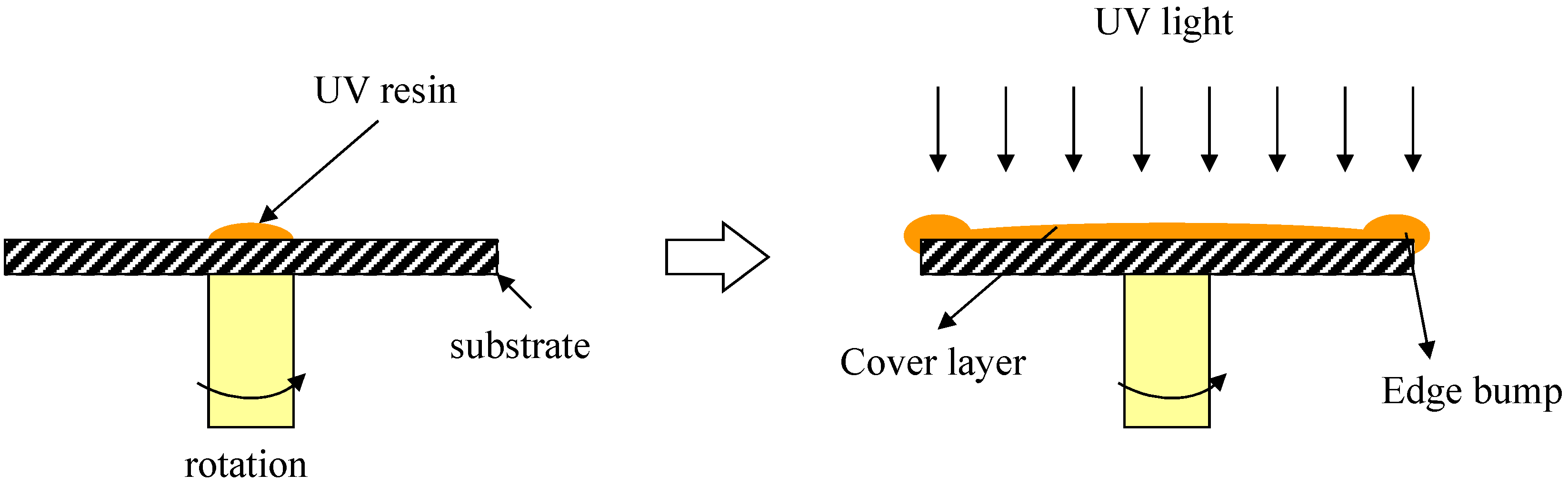
The experiment was conducted in order to measure the film thickness distribution after an ultraviolet (UV) curing process in different conditions, as shown in Figure 1. The UV-curable resin (Sigma-Aldrich, Darmstadt, Germany) consisted of a urethan acrylate oligomer, acrylate oligomer, acrylate monomer, vinyltriethoxysilane, acrylic acid, and photoinitiator. A predetermined amount of UV-curable resin was supplied as a falling jet onto the center of the polycarbonate disk by high precision pump to supply the resin accurately. The disks used in the experiment were 32, 50.8 and 120 mm in diameter. The mass of resin applied onto the disk was determined by the disk size and the viscosity, as summarized in Table 1, where D represents disk diameter. In the spin coating process, the resin was distributed by spinning of the disk with the desired rotation speed from 1000 to 3000 rpm for 20 s. Then, the disk was stopped. Finally, UV light was used to cure the resin on the surface of the disk. It should be noted that in this experiment, UV irradiation captured the surface layer formation after spin coating process. With this, hydrodynamic characteristics of rotating disk only affected the thickness variation in the layer. The thickness of the layer manufactured by spin coating was measured along the radius of the disk by using a non-contact profiler (Ellipsometer, VK-X3000, Keyence, Itasca, IL, USA). Three types of resins that have different viscosities but relatively little differences in surface tension and density were chosen in order to investigate the effect of viscosity on the film thickness variation. Table 1 shows a summary of the experimental conditions.
3. Results and Discussion
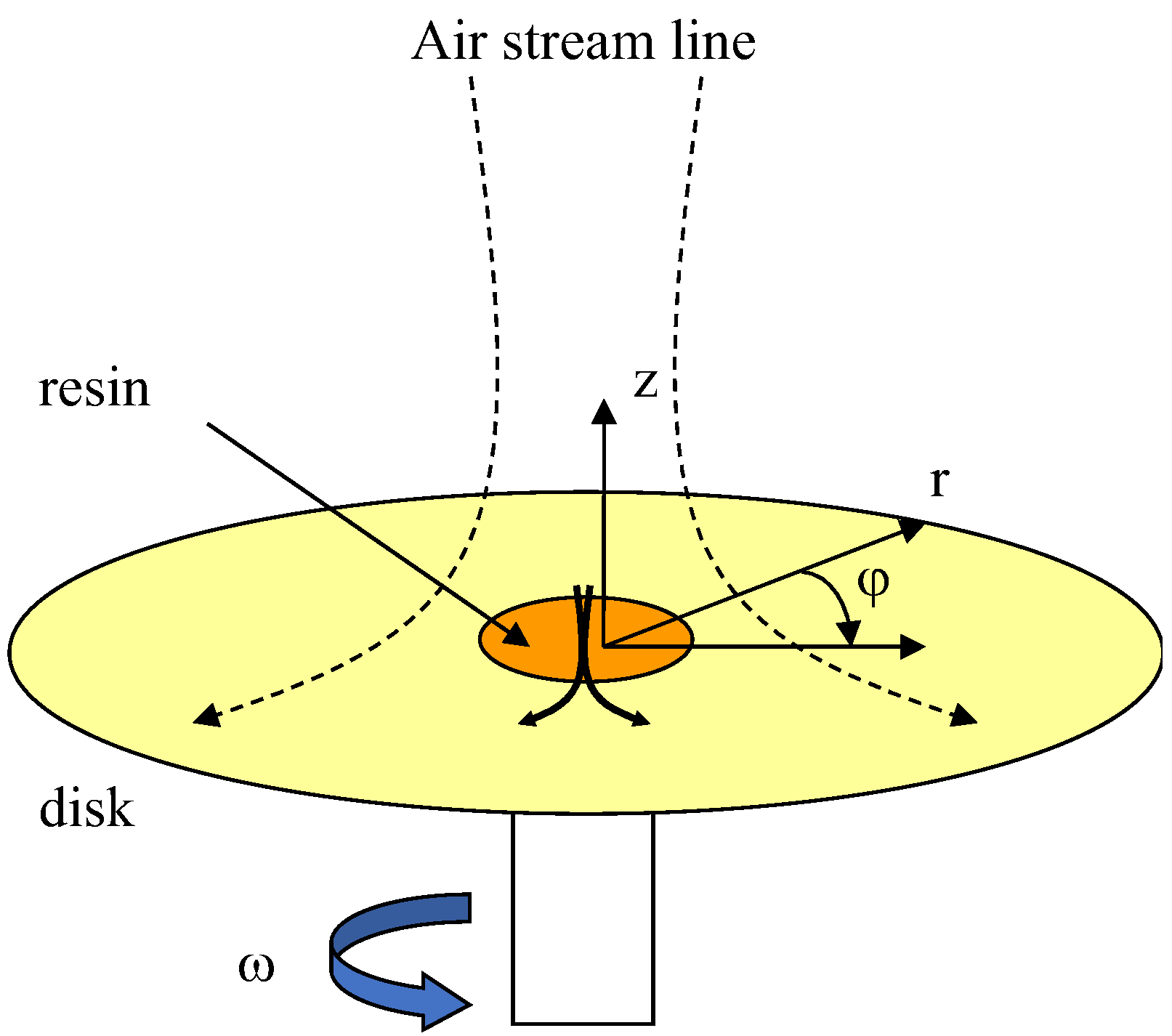
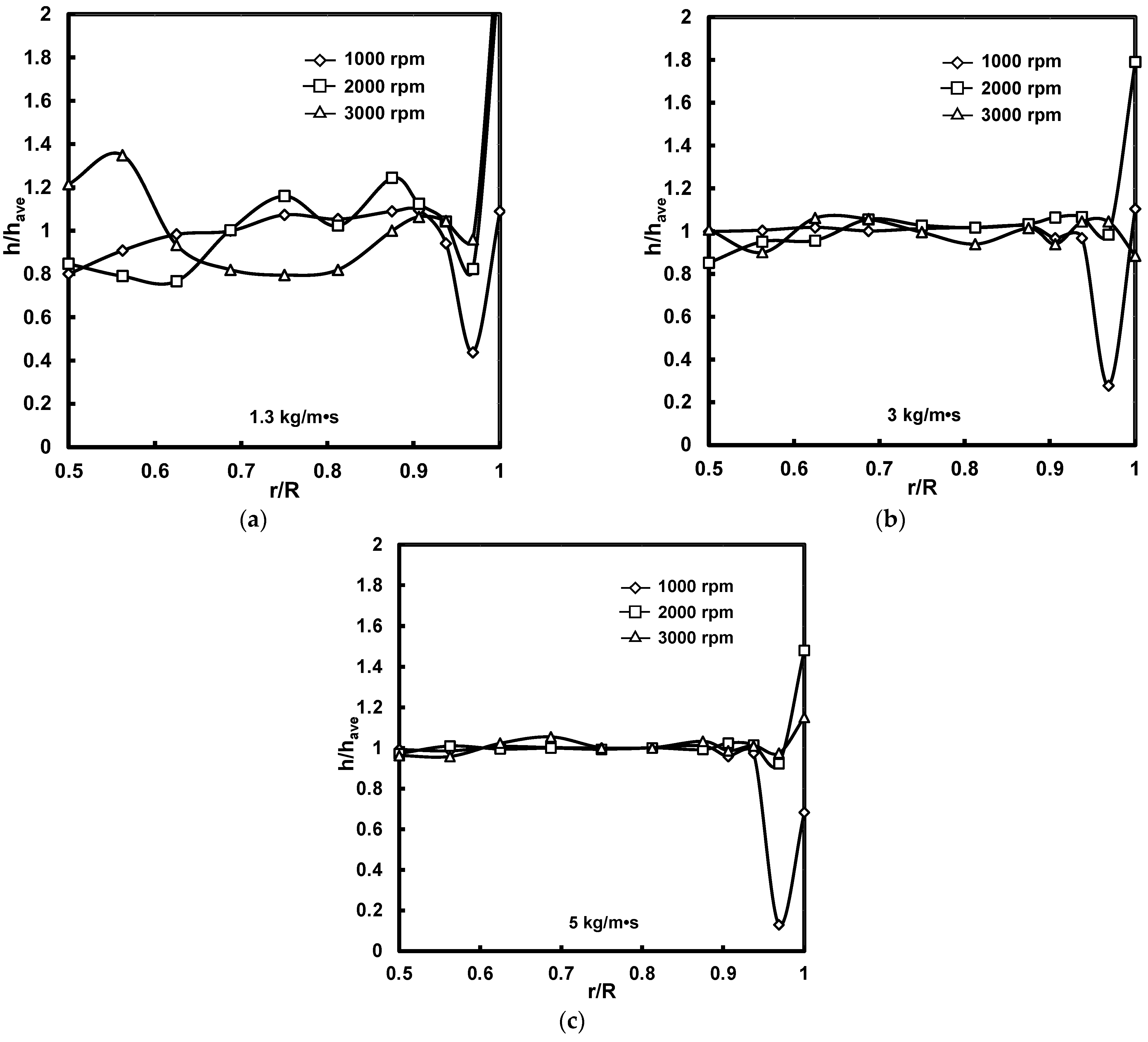
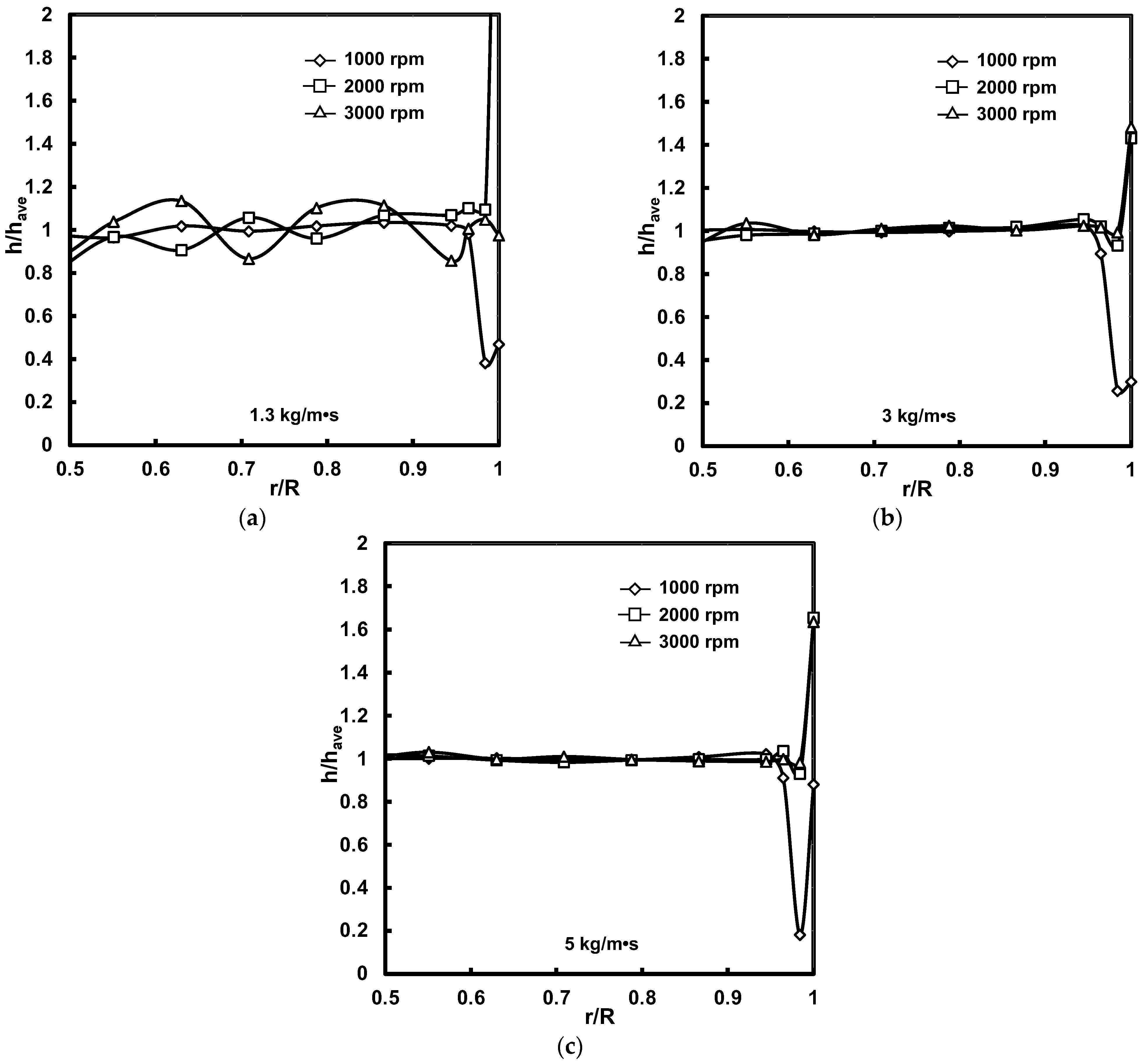
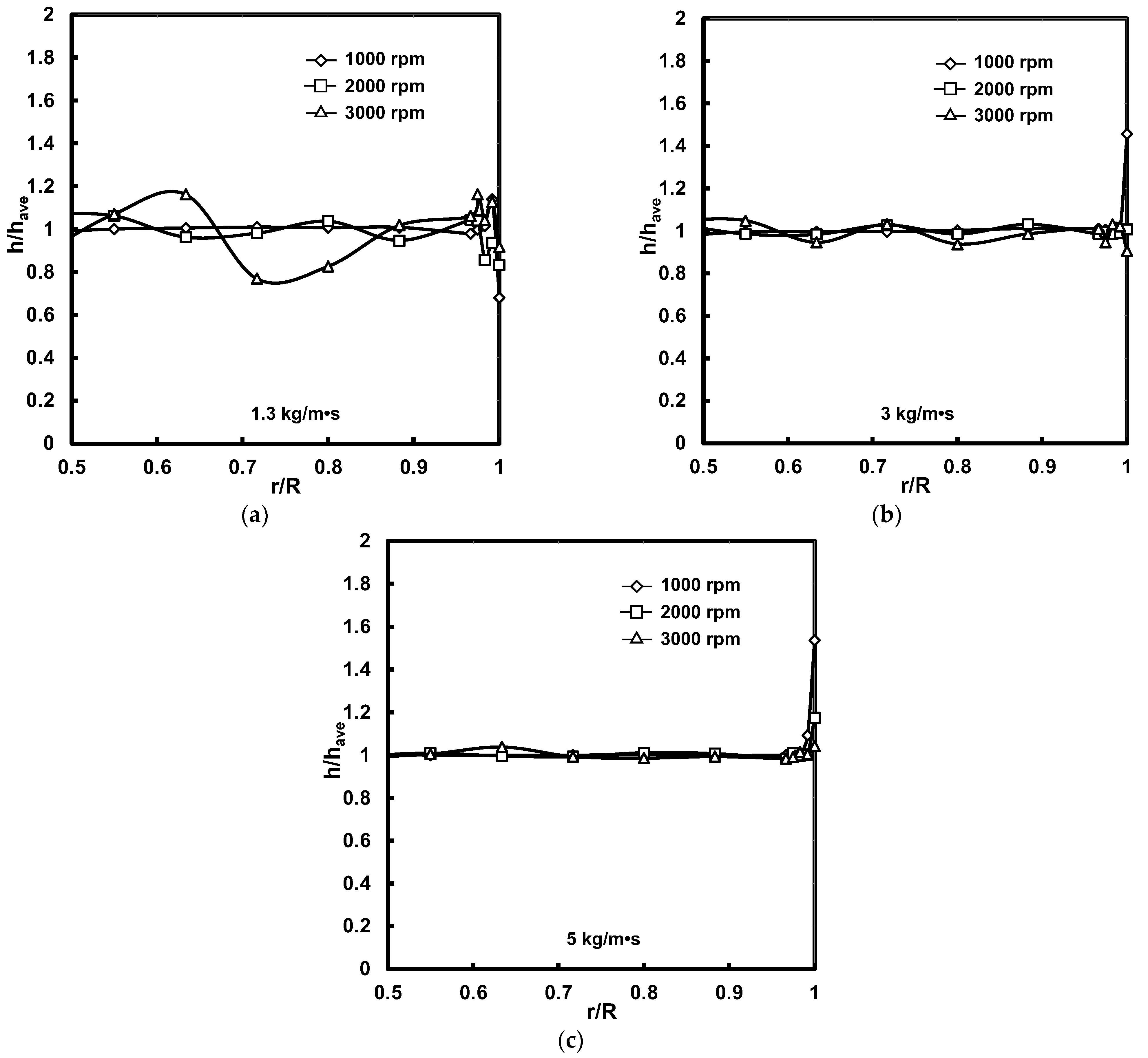
The film’s flow on a rotating disk can be simply described with cylindrical coordinates, as shown in Figure 2. The measured average thickness was varied from 18.7 to 146 μm in accordance to the experimental conditions of rotation speed, disk diameter, and type of resin. The weights of applied mass were from 1 to 2 g for the disk diameters of 32 and 50.8 mm, and from 5.9 to 6.3 g for 120 mm. The experimental results of film thickness distributions for all the conditions are presented in Figure 3, Figure 4 and Figure 5. The variation in film thickness was strongly dependent on the viscosity and rotation speed. The thickness seemed to vary within a certain amplitude from the average height. This suggests that the wavy form of the film was induced by the instability of flow during the spinning of the disk. The amplitude of the wave was proportional to the rotation speed and inversely proportional to the viscosity, as shown in the graphs. Hence, the wavy form of the film observed in the experiments was analyzed in terms of standard deviation and average film height in relation to Ekman number (E = υ/ωR2), which is a non-dimensional measure of viscous force and Coriolis force.
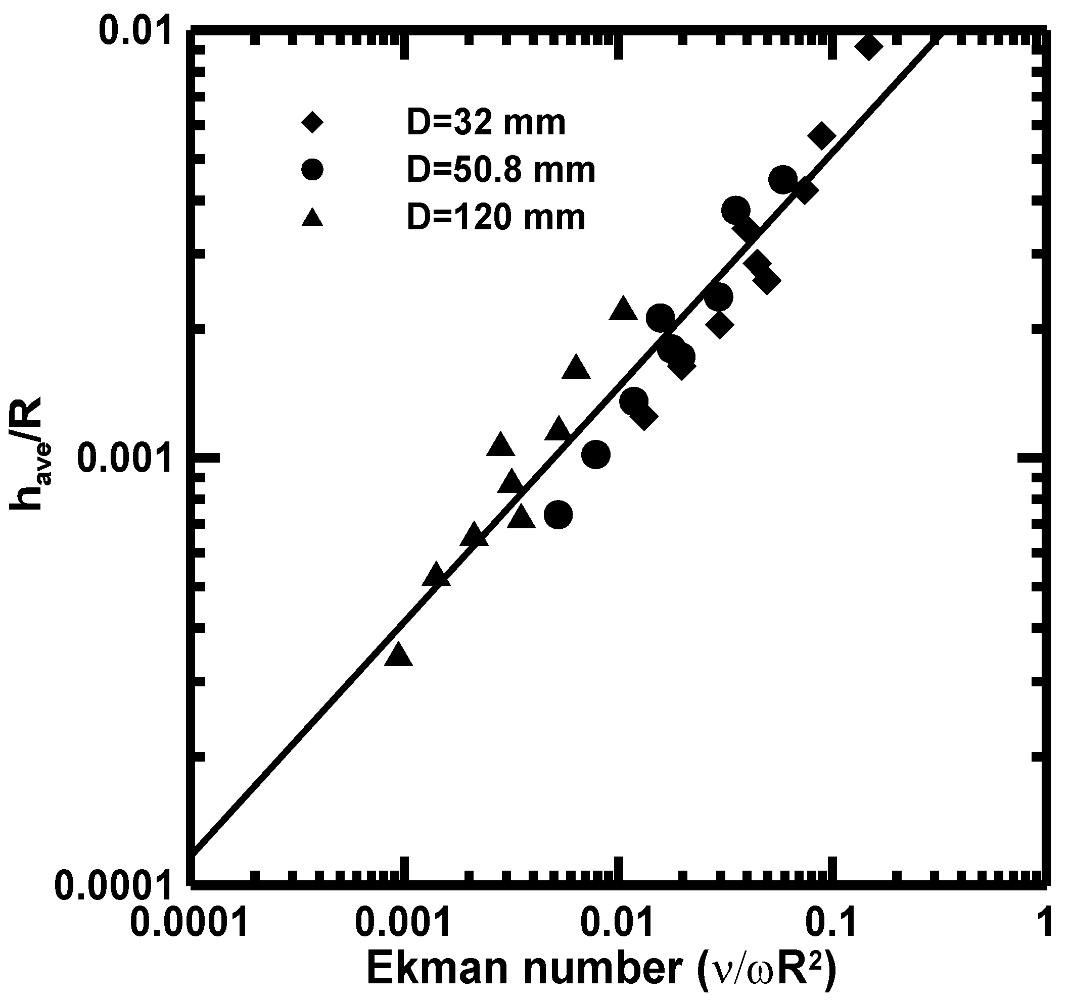
The average height (have) divided by radius of the disk (R) was plotted in Figure 6. The following formula was acquired from the data fitting, where υ and ω represent viscosity and angular velocity, respectively.
The average film thickness was proportional to the Ekman number, which implies Coriolis force and viscous force were dominant with our experimental conditions. In the case of a constant flow rate, the average film height at a local radius has been described as a function of viscosity, angular velocity, radial distance, and flow rate as well [29,30]. However, the relation in Equation (1) shows that average thickness is independent of flow rate and only depends on Ekman number. In this range of applied mass, no relationship was found between applied mass and thickness in the experimental results. It is thought that the average thickness of the liquid film reached a steady state when the viscous force and the Coriolis force were balanced, so as to maintain constant thickness, which was irrelevant to the masses applied within our experiments. Therefore, the average thickness can be described with the Ekman number. The Reynolds number at the end of disk, which was in the order of 10−4, also supports the validity of the explanation of the film thickness’s dependency on the Ekman number, as such a low Reynolds number means less significance for the flow rate compared to other effects. As a result, the film thickness is proportional to the Ekman number in the relation of Equation (1).
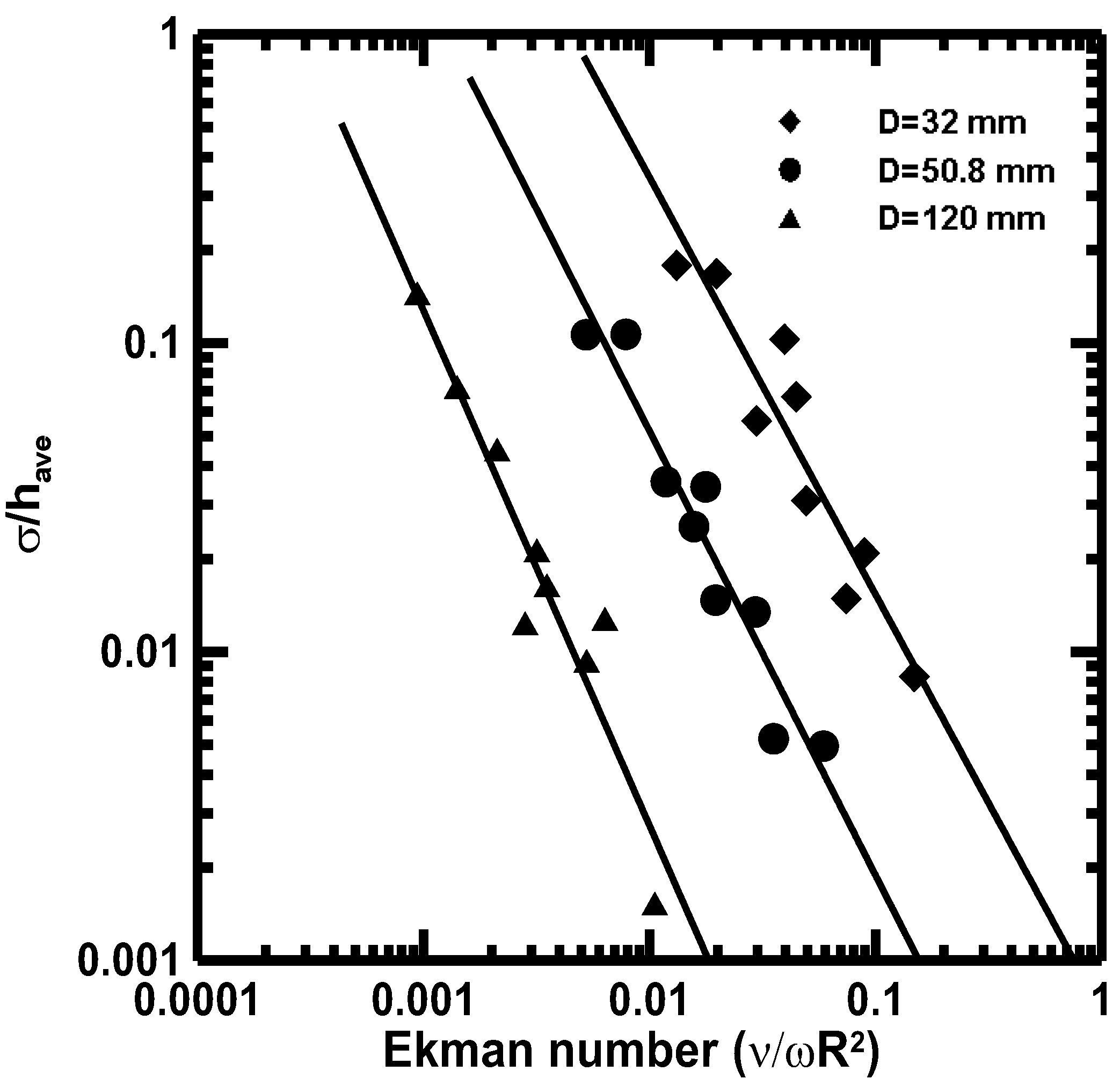
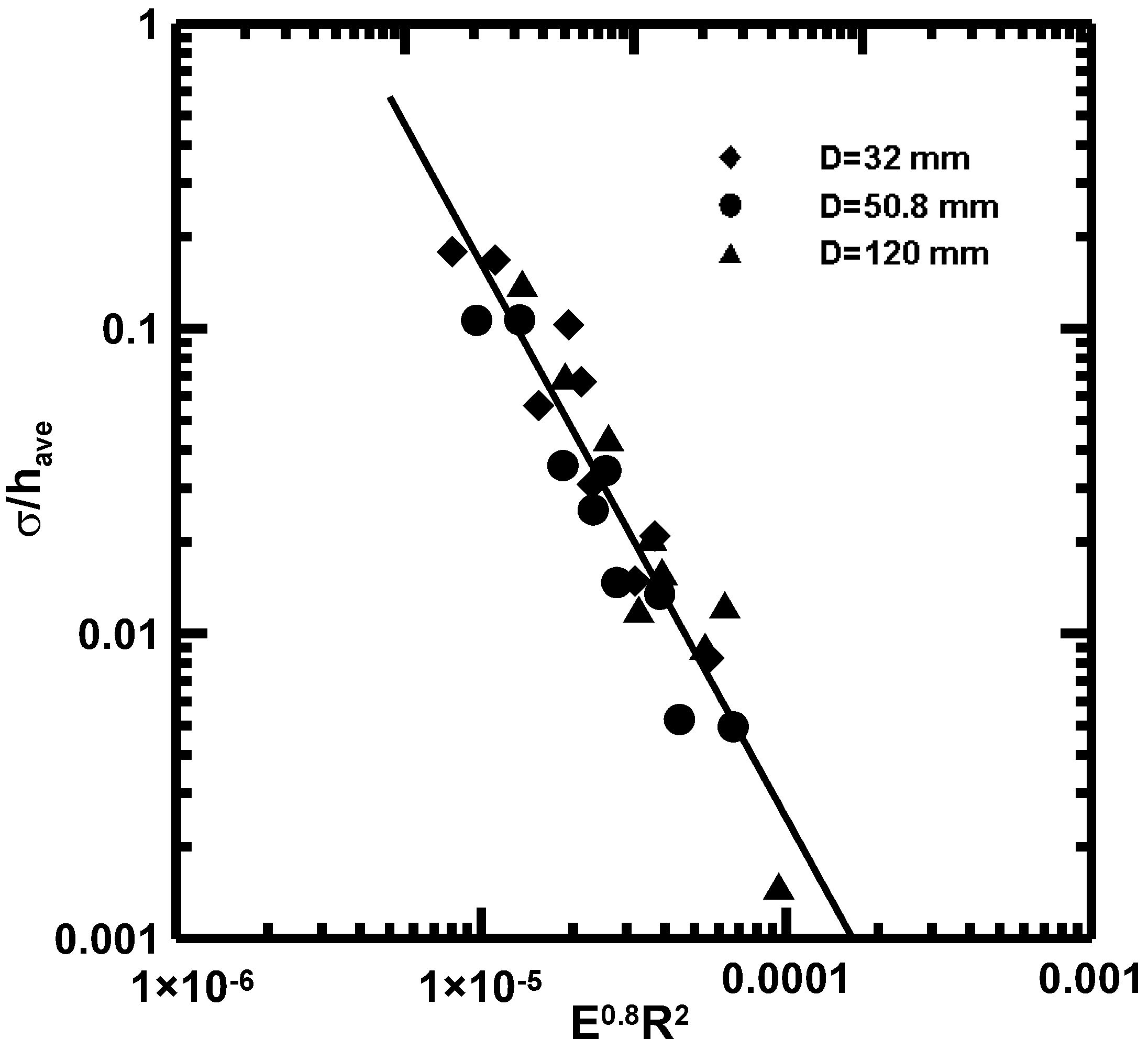
Figure 7 shows the relationship between standard deviation (σ) divided by average height and Ekman number. The deviation was inversely proportional to the Ekman number, and the magnitude seemed to be dependent on the disk radius. In other words, a large Ekman number and a large disk diameter induced small deviation in the film’ thickness. In numerical analysis conducted for constant flow rate by Matar et al. [25], decreasing the value of E, which corresponds to increasing the significance of the Coriolis force, led to stabilizing the film flow. This is the opposite of the result which is shown in Figure 7. However, the large value of Ekman number means a relatively strong viscous effect on the flow so as to stabilize the film flow. It is inferred that the large viscous force suppressed the unstable film flow induced by the Coriolis force. In order to achieve a flat surface for the film, it is significant that the spin coating process is controlled with a large Ekman number which depends on the disk radius. The standard deviation was replotted by combining Ekman number and disk radius to quantify the dependency on the disk radius. Figure 8 shows the stability of the film was inversely proportional to the square of disk radius and Ekman number to the power of 0.8. Nonetheless, the reason for the dependency of stability on the disk radius is still not clear but presumed to be in accordance with inertial effects. Further investigation is still going on in this area.
Edge bumps are one of the serious disadvantages of the spin coating process when the process is applied to IC circuits and optical disk manufacturing. The hydraulic jump is formed at the outer edge of rotating disk during the film’s flow [27]. At the hydraulic jump, the height of the liquid surface suddenly varies, and the flow also changes from a supercritical to a subcritical flow [31]. The observations from previous works are similar to those of the experimental results presented in Figure 3, Figure 4 and Figure 5. It is assumed that the observed edge bump formed at the outer edge of the disk was caused by a hydraulic jump. Leshev and Peev [28] successfully described the position of the hydraulic jump by using Buckingham’s Pi theorem by means of four dimensionless groups which are presented in Equation (2). The beginning positions of the edge bump for experimental conditions were recorded, where the thickness increased steeply. However, when the thickness variation was large compared to average thickness, it was difficult to discriminate whether the steep increase in thickness came from wavy form or hydraulic jump. In order to predict hydraulic jump position reasonably, the data were used when the changes in thickness were below 3% of average thickness. This criterion also makes the obtained relation useful to practical applications. The radial position of the hydraulic jump beginning (r’) is supposed to depend on the rotation speed (ω); the volumetric flow rate (Q); and the material properties of density (ρ), viscosity (υ), and surface tension (σ). The following equation was acquired by non-dimensional analysis [18].
The values of the powers and the coefficient, A, were derived by regression analysis from the experimental data. While Leshev and Peev [28] performed the analysis for constant flow rate of the liquid on the rotating disk, the author was concerned about the change in thickness after applying a certain amount of liquid to the center of the disk. The flow rate was explicitly evaluated by using the momentum equation of a polar coordinate system, Equation (4), where vr is velocity in the radial direction and z is the coordinate in the vertical direction, as shown in Figure 2.
Finally, the variables of Equation (2) were calculated by regression analysis of the experimental data with the following ranges of non-dimensional numbers.
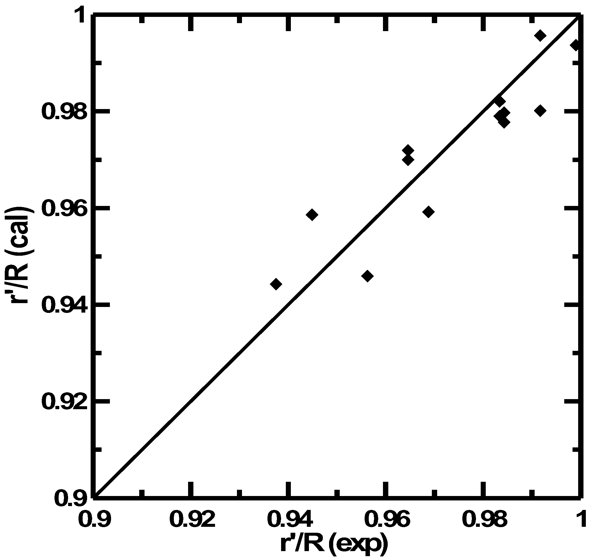
This result was compared with the experimental data of edge bump positions, as shown in Figure 9. The positions of edge bumps can be predicted by non-dimensional numbers with good accuracy, even though a high Ekman number was found alongside a relatively low Reynolds number. It can be seen that the position of the hydraulic jump was successfully described by the Ekman number, Weber number, and Reynolds number. Within the ranges of the non-dimensional numbers, the Weber number was found to be a more significant factor than the other two non-dimensional numbers. This means that the hydraulic jump corresponded to the ratio of surface tension to centrifugal force. Equation (6) successfully describes the positions of edge bumps when adopting the hydraulic jump relation. This is the evidence that the edge bump observed after solidification of the liquid film was induced by the hydraulic jump during spinning of the disk.
4. Conclusions
The profile of the film formed by spin coating was successfully described by applying hydrodynamic theory. The viscosity and rotation speed of the disk affected the characteristics of the thickness. It was shown that the film thickness and deviation of the thickness can be predicted by the Ekman number. The Coriolis effect caused by rotation of the disk was thought to induce flow instability, which led to the wavy form of the film manufactured by spin coating process. The edge bump position was expressed by the power law relationship of Ekman, Weber, and Reynolds numbers. We inferred that the hydraulic jump induces the edge bump which was observed after curing the film by UV light. The relationships obtained by this work are expected to be useful to predict the thickness, thickness variation, and position of an edge bump in the spin coating process.
Funding
This work is supported by the National Research Foundation of Korea (NRF), funded by the Korean government (MSIT) (number NRF-2019R1A2C1002212).
Institutional Review Board Statement
Not applicable.
Informed Consent Statement
Not applicable.
Data Availability Statement
Data sharing is not applicable to this article.
Conflicts of Interest
The authors declare no conflict of interest.
References
- Kitamura, A.; Hasegawa, E.; Yoshizawa, M. Asymptotic analysis of the formation of thin liquid film in spin coating. Fluid Dyn. Res. 2022, 30, 107. [Google Scholar] [CrossRef]
- Elmansouri, A.; Outzourhit, A.; Oueriagli, A.; Lachkar, A.; Hadik, N.; Achour, M.E.; Abouelaoualim, A.; Malaoui, A.; Berrada, K.; Ameziane, E.L. Fabrication and characterization of Schottky diodes and thin films based on poly (o-toluidine) deposited by spincoating technique. Synth. Met. 2010, 160, 1487–1492. [Google Scholar] [CrossRef]
- Yu, C.L.; Sakthinathan, S.; Lu, M.T.; Yu, S.T.; Kuo, C.Y.; You, Y.F.; Chiu, T.W. CuAlO2/AIN double-layer thin film prepared by the spin coating approach. Thin Solid Film. 2022, 753, 139260. [Google Scholar] [CrossRef]
- Muhammad, S.; Nomaan, A.T.; Idris, M.I.; Rashid, M. Structural, optical and electrical investigation of low-temperature processed zinc oxide quantum dots based thin films using precipitation-spin coating on flexible substrates. Phys. B Phys. Condens. Matter 2022, 635, 413806. [Google Scholar] [CrossRef]
- Dehghan, M.; Behjat, A. Deposition of zinc oxide as an electron transport layer in planar perovskite solar cells by spray and SILAR methods comparable with spin coating. RSD Adv. 2019, 9, 20917–20924. [Google Scholar] [CrossRef] [Green Version]
- Lang, J.; Wang, J.; Zhang, Q.; Li, X.; Han, Q.; Wei, M.; Sui, Y.; Wang, D.; Yang, J. Chemical precipitation synthesis and significant enhancement in photocatalytic activity of Ce-doped ZnO nanoparticles. Ceram. Int. 2016, 42, 14175–14181. [Google Scholar] [CrossRef]
- Ziti, A.; Hartiti, B.; Labrim, H.; Doubi, Y.; Nkuissi, H.J.T.; Nouria, Y.; Fadili, S.; Batan, A.; Tahri, M.; Ridah, A.; et al. Investigation of CZTS absorber layer deposited by spin coating technique for photovoltaic applications. Mater. Today Proc. 2022, 53, 355–360. [Google Scholar] [CrossRef]
- Tchognia, J.H.N.; Arba, Y.; Hartiti, B.; Ridah, A.; Ndjaka, J.M.; Thevenin, P. Effect of sulfurization time on properties of Cu2ZnSnS4 thin films obtained by sol-gel deposited precursors. Opt. Quant. Electron. 2016, 48, 134. [Google Scholar] [CrossRef]
- Tchognia, J.H.N.; Arba, Y.; Hartiti, B.; Ridah, A.; Ndjaka, J.M.; Ridah, A.; Thevenin, P. Solution-based deposition of wurzite copper zinc tin sulfide nanocrystals as a novel absorber in thin film solar cells. Opt. Quant. Electron. 2016, 48, 255. [Google Scholar] [CrossRef]
- Tanaka, K.; Moritake, N.; Uchiki, H. Preparation of Cu2ZnSnS4 thin film by sulfurizing sol-gel deposited precursors. Energy Mater. Sol. Cells 2007, 91, 1199–1201. [Google Scholar] [CrossRef]
- Heinz, B.; Eisenhammer, T.; Dubs, M.; Yavaser, C.; Pfaff, T. Blu-ray disc cover layer production using spin coating technology. Opt. Data Storage Top. Meet. 2006, 117–119. [Google Scholar]
- Decre, M.M.J.; Vromans, P.H.H.G.M. Cover layer technology for the high-numerical-aperture digital video recording system. Jpn. J. Appl. Phys. 2000, 39, 775. [Google Scholar] [CrossRef]
- Get, R.; Islam, S.M.; Singh, S.; Mahala, P. Organic polymer bilayer structures for applications in flexible solar cell T devices. Microelectron. Eng. 2020, 222, 111200. [Google Scholar] [CrossRef]
- Zheng, Q.; Wang, C.; Ma, G.; Jin, M.; Chen, S.; Lai, Y.; Yu, J. Annealing temperature impact on Sb2S3 solar cells prepared by spin-coating method. Mater. Lett. 2019, 243, 104–107. [Google Scholar] [CrossRef]
- Kim, W.; Park, J.; Kim, H.; Pak, Y.; Lee, H.; Jung, G.Y. Sequential dip-spin coating method: Fully infiltration of MAPbI3-xClx into mesoporous TiO2 for stable hybrid perovskite solar cells. Electrochim. Acta 2017, 245, 734–741. [Google Scholar] [CrossRef] [Green Version]
- Lee, J.H.; Jung, K.; Lee, M.J. Influence of spin-coating methods on properties of planar solar cells based on ambient-air-processed triple-cation mixed-halide perovskites. J. Alloys Compd. 2021, 879, 160373. [Google Scholar] [CrossRef]
- Jiang, J.; Tao, H.J.; Chen, S.; Tan, B.; Zhou, N.; Zhu, L.; Zhao, Y.; Wang, Y.; Tao, J. Efficiency enhancement of perovskite solar cells by fabricating as-prepared film before sequential spin-coating procedure. Appl. Surf. Sci. 2016, 371, 289–295. [Google Scholar] [CrossRef] [Green Version]
- Padilla, J.U.; Graells, M.; Valle, J.S.; Serrano, J.L. A viscosity-mediated model for relating gloss and film thickness of coatings. Prog. Org. Coat. 2019, 136, 10595. [Google Scholar]
- Emslie, A.G.; Bonner, F.T.; Peck, L.G. Flow of a viscous liquid on a rotating disk. J. Appl. Phys. 1958, 29, 858. [Google Scholar] [CrossRef]
- Jenekhe, S.A.; Schuldt, S.B. Coating flow of non-Newtonian fluids on a flat rotating disk. Ind. Eng. Chem. Fundam. 1984, 23, 432. [Google Scholar] [CrossRef]
- Tu, Y.O. Contact line slippage of fluid flow on a rotating disk. J. Colloid Interface Sci. 1986, 29, 237. [Google Scholar] [CrossRef]
- Meyerhofer, D. Characteristics of resist films produced by spinning. J. Appl. Phys. 1978, 49, 3993. [Google Scholar] [CrossRef] [Green Version]
- Lin, M.C.; Chen, C.K. Finite amplitude long-wave instability of a thin viscoelastic fluid during spin coating. Appl. Mathmatical Model. 2012, 36, 2536–2549. [Google Scholar] [CrossRef]
- Sisoev, G.M.; Matar, O.K.; Lawrence, C.J. Axisymmetric wave regimes in viscous liquid film flow over a spinning disk. J. Fluid Mech. 2003, 495, 385. [Google Scholar] [CrossRef]
- Matar, O.K.; Sisoev, G.M.; Lawrence, C.J. Evolution scales for wave regimes in liquid film flow over a spinning disk. Phys. Fluids 2004, 16, 1532. [Google Scholar] [CrossRef]
- Leneweit, G.; Roesner, K.G.; Koehler, R. Effect of surfactants on the stability of thin liquid film flow on a rotating disk. J. Colloid Interface Sci. 2003, 260, 349. [Google Scholar] [CrossRef]
- Tomas, S.; Faghri, A.; Hankey, W. Experimental analysis and flow visualization of a thin liquid film on a stationary and rotating disk. J. Fluids Eng. 1991, 113, 73. [Google Scholar] [CrossRef]
- Leshev, I.; Peev, G. Film flow on a horizontal rotating disk. Chem. Eng. Proc. 2003, 42, 925. [Google Scholar] [CrossRef]
- Charwat, A.F.; Kelly, R.E.; Gazley, C. The flow and stability of thin liquid films on a rotating disk. J. Fluid Mech. 1972, 53, 227. [Google Scholar]
- Espig, H.; Hoyle, R. Waves in a thin liquid layer on a rotating disk. J. Fluid Mech. 1965, 22, 671. [Google Scholar] [CrossRef]
- Yokoi, K.; Xiao, F. Mechanism of structure formation in circular hydraulic jumps: Numerical studies of strongly deformed free-surface shallow flows. Physica D 2002, 161, 202. [Google Scholar] [CrossRef]
Figure 1.
Schematic of the spin coating process for an optical record disk.

Figure 2.
Coordinate system of film flow on a rotating disk.

Figure 3.
Radial distribution of film thickness: 32 mm disc diameter. (a) 1.3 kg/m⋅s, (b) 3 kg/m⋅s, (c) 5 kg/m⋅s.
Figure 3.
Radial distribution of film thickness: 32 mm disc diameter. (a) 1.3 kg/m⋅s, (b) 3 kg/m⋅s, (c) 5 kg/m⋅s.

Figure 4.
Radial distribution of film thickness: 50.8 mm disc diameter. (a) 1.3 kg/m⋅s, (b) 3 kg/m⋅s, (c) 5 kg/m⋅s.
Figure 4.
Radial distribution of film thickness: 50.8 mm disc diameter. (a) 1.3 kg/m⋅s, (b) 3 kg/m⋅s, (c) 5 kg/m⋅s.

Figure 5.
Radial distribution of film thickness: 120 mm disc diameter. (a) 1.3 kg/m⋅s, (b) 3 kg/m⋅s, (c) 5 kg/m⋅s.
Figure 5.
Radial distribution of film thickness: 120 mm disc diameter. (a) 1.3 kg/m⋅s, (b) 3 kg/m⋅s, (c) 5 kg/m⋅s.

Figure 6.
Average thickness of the film on the disk vs. Ekman number.

Figure 7.
Thickness variation nondimensionalized by average thickness vs. Ekman number.

Figure 8.
The standard deviation of the thickness described by Ekman number and disk radius.

Figure 9.
Comparison of edge bump positions obtained by calculation and experiment.


Table 1.
Experimental conditions.
| Disk Diameter (mm) | Rotation Speed (rpm) | Resin | ||||
|---|---|---|---|---|---|---|
| Viscosity (kg/m·s) | Surface Tension (N/m) | Density (kg/m3) | Mass Applied (g) | |||
| D = 32, 50.8 | D = 120 | |||||
| 32 | 1000 | 1.3 | 0.0382 | 1230 | 2 | 6.3 |
| 50.8 | 2000 | 3 | 0.0398 | 1230 | 1.8 | 6 |
| 120 | 3000 | 5 | 0.037 | 1260 | 1 | 5.9 |
Publisher’s Note: MDPI stays neutral with regard to jurisdictional claims in published maps and institutional affiliations. |
© 2022 by the author. Licensee MDPI, Basel, Switzerland. This article is an open access article distributed under the terms and conditions of the Creative Commons Attribution (CC BY) license (https://creativecommons.org/licenses/by/4.0/).
Share and Cite
MDPI and ACS Style
Park, H. Hydrodynamic Analysis of the Thickness Variation in a Solid Film Formed by a Spin Coating Process. Coatings 2022, 12, 698. https://0-doi-org.brum.beds.ac.uk/10.3390/coatings12050698
AMA Style
Park H. Hydrodynamic Analysis of the Thickness Variation in a Solid Film Formed by a Spin Coating Process. Coatings. 2022; 12(5):698. https://0-doi-org.brum.beds.ac.uk/10.3390/coatings12050698
Chicago/Turabian StylePark, Heesung. 2022. "Hydrodynamic Analysis of the Thickness Variation in a Solid Film Formed by a Spin Coating Process" Coatings 12, no. 5: 698. https://0-doi-org.brum.beds.ac.uk/10.3390/coatings12050698
Note that from the first issue of 2016, this journal uses article numbers instead of page numbers. See further details here.