
Immune Optimization of Welding Sequence for Arc Weld Seams in Ship Medium-Small Assemblies

1
School of Mechanical Engineering, Jiangsu University of Science and Technology, Zhenjiang 212100, China
2
Jiangsu Institute of Automation, Lianyungang 222006, China
*
Author to whom correspondence should be addressed.
Coatings 2022, 12(5), 703; https://0-doi-org.brum.beds.ac.uk/10.3390/coatings12050703
Submission received: 14 February 2022
/
Revised: 8 March 2022
/
Accepted: 17 March 2022
/
Published: 20 May 2022
(This article belongs to the Special Issue Progress in Coatings Deposition by Advanced Welding and Welding-Related Processes)
Abstract
:The arc weld seam is a common form in ship medium-small assemblies. In order to reduce the deformation of the welded parts with an arc weld seam, and then improve the welding quality, research on the optimization of welding sequences based on the artificial immune algorithm is carried out in this paper. First, the formation mechanism of welding deformation is analyzed by the thermo-elastic-plastic finite element method; next, the reduction in the welding deformation is taken as the optimization goal, and the welding sequence optimization model for the arc weld seam is constructed under the condition of boundary constraints; then, an immune clonal optimization algorithm based on similar antibody similarity screening and steady-state adjustment is proposed, and its welding sequence optimization ability is improved through antibody screening and median adjustment. Finally, the welding sequence optimization tests are carried out based on the Ansys platform. Numerical tests of a typical arc weld seam show that different welding sequences will cause different welding deformations, which verifies the importance of welding sequence optimization. Furthermore, the numerical test results of four different types of welds in ship medium-small assemblies demonstrated that the use of distributed optimization algorithms for welding sequence optimization can help reduce the amount of welding deformations, and the immune clonal algorithm, based on antibody similarity screening and steady-state adjustment, achieves the optimal combination of the welding sequence. Compared with the other three optimization algorithms, the maximum welding deformation caused by the welding sequence optimized by the proposed immune clonal algorithm is reduced by 3.1%, 4.0%, and 3.4%, respectively, the average maximum welding deformation is reduced by 3.5%, 5.5%, and 4.7%, respectively, and the convergence generation of the optimization algorithm is reduced by 16.8%, 13.1% and 14.5%, respectively, which further verifies the effectiveness and superiority of the proposed immune clonal algorithm in the optimization of welding sequences.
1. Introduction
Welding is the core process in shipbuilding, and there are a large number of arc welded structures in the bow, stern and bilge of ships. Therefore, there are not only straight weld seams but also a large number of arc weld seams in ship medium-small assemblies. At present, the automatic welding of straight weld seams is relatively mature, but the arc weld seams have always been a difficult welding technology due to the irregular seam shape and the continuous change of welding direction, and how to reduce welding deformation is the focus of particular attention. In arc welding, the transverse and longitudinal stresses produced by welding are different from the internal stresses perpendicular to the weld seam and parallel to the weld seam produced in straight welding. Therefore, the internal stress of the base metal after arc welding is squeezed and contracted. The situation cannot be characterized by the internal lateral and longitudinal deformations that occur in general straight welding. There is also a big difference between the total deformation in arc seam welding and the total deformation in straight seam welding due to strains in different directions. A large number of studies have shown that the defects of welding deformation are not only affected by the welding process but also directly related to the welding sequence, tack welds distribution, etc. [1]. However, the welding deformation caused by tack welds distribution is much smaller than the deformation caused by different welding sequences. In addition, different from welding sequence optimization, the welding deformation research based on tack welds distribution mainly focuses on quantitative analysis, and it is difficult to carry out global intelligent optimization by constructing a multivariate objective function. Therefore, how to optimize the welding sequence to control the welding deformation has become the research focus of domestic and foreign experts [2]. Liu et al. [3] carried out a study on the effect of welding sequences on welding deformation of large-sized thick plate structures based on the local-global mapping method. For the engineering vehicle frame, four welding sequences were designed. Numerical analysis and experiments demonstrated that the optimized welding sequence (i.e., laterally symmetrical simultaneous welding) can reduce the maximum deformation by 43%, which verifies the importance of the welding sequence in reducing the welding deformation of the engineering vehicle frame. Aiming at the welding of TA15 titanium alloy panel for aircraft, Dong et al. [4] constructed the double ellipsoid heat source models for the TIG (Tungsten Inert Gas) penetration welding process by comparing the macroscopic morphology and residual stress of the weld section and simulated the panel deformation under five welding sequences. The numerical test results demonstrated that the sequential welding from one side will cause the middle edge of the thin panel to bulge, and the maximum deformation is 3.9 mm; however, the optimized symmetrical welding can effectively control the panel deformation. Aiming at the vehicle bumper with 6061-T6 aluminum alloy thin-walled structure, Guo et al. [5] carried out the simulation analysis of temperature field and stress-strain field under four different welding sequences based on nonlinear elastic-plastic finite element method. The numerical simulation results showed that the optimal welding sequence was to weld the welds in sequence along the length of the anti-collision beam and then weld the remaining welds in the opposite direction. In order to solve the deformation control problem of subway floors in friction stir welding, He et al. [6] carried out the study on floor welding deformation under five welding sequences by using the life–death element technology based on the shrinkage strain method. The numerical analysis results showed that the symmetrical welding method should be adopted as much as possible when designing the welding sequence. When welding the back weld of the floor, the inner weld seam should be welded first, and then the outer weld seam should be welded, which can effectively reduce the welding deformation. The above research on the influence of welding sequences on welding deformation is mainly based on the enumeration method, which is difficult to obtain for the globally optimal welding sequence for long weld seams or multiple weld seams. With the development of computer technology, the global optimization technology of welding sequences based on intelligent algorithms has emerged in recent years [7,8,9]. In order to reduce the welding deformation of the flat plate, Elesztos [10] first constructed an optimization model for the welding layer around the butt-welding groove of the flat plate, and then the genetic algorithm was introduced to optimize the welding sequence globally. Compared with the welding deformation caused by the traditional welding sequence, the optimized welding sequence based on the GA (Genetic Algorithm) reduces the welding deformation by 12.5%, which verifies the effectiveness of the intelligent algorithm in the global welding sequence optimization. From the existing research results, it can be seen that the analysis of the internal force change of the material during welding is of great significance to the control of welding deformation [11,12], and the use of distributed global intelligent algorithms for welding sequence optimization can help improve optimization results and optimization efficiency. Numerical test results of multiple welded parts also verify the effectiveness of the proposed welding sequence optimization algorithm for arc welds. However, there are few studies on the welding sequence optimization for ship arc welds. In view of this, on the basis of welding thermal deformation theory, a welding sequence optimization model of ship arc weld is constructed, and a new immune clonal algorithm is introduced to realize the global optimization of the welding sequence. Numerical test results of various weldments verify the effectiveness of the proposed method.
2. Theory of Welding Thermal Deformation
In order to effectively construct the welding sequence optimization model, the research on the deformation of the welded parts after the thermal load is carried out is based on the thermo-elastoplastic finite element method, that is, the welded structure is first spatially discrete, and the temperature field of each element is modeled to obtain the temperature of the welded node. Then, the relationship between node stress and strain is obtained according to the change of nodal temperature. Finally, the amount of welding deformation is obtained.
2.1. Determination of Welding Heat Source Model
For ship welding, the common welding method is non-melting electrode gas shielded arc welding, the protective medium is nitrogen, and the tungsten rod is used as the electrode to generate an arc between the electrode and the workpiece for welding. In this paper, the heat generation rate of the weld unit is calculated by the heat generation rate equation [13]. The heat generation rate is applied to the unit as a body load and can be used as the heat load in the unit to simulate the influence of the non-melting gas shielded welding heat source on the base metal. In order to produce the calculation results in line with the actual situation, the welding current is set to 240 A, the welding voltage is set to 25 V [14], and the welding speed is set to 10 mm/s. In addition, the base material unit is preheated before the transient analysis is performed, and the temperature of the base material is preheated to 50 °C.
where Hgen is the heat generation rate, k is the thermal efficiency of the welding heat source, U is the welding voltage, I is the welding current, v is the welding speed, ∆t is the time of each load step, A is the cross-sectional area of the weld seam.
2.2. Calculation of Node Displacement Increment
According to the thermo-elastic-plastic finite element theory, the full strain increment of the elastic zone after the material yields can be assumed to be composed of the elastic strain increment and the thermal strain increment [15].
where is the full strain increment, is the elastic strain increment, and is the thermal strain increment.
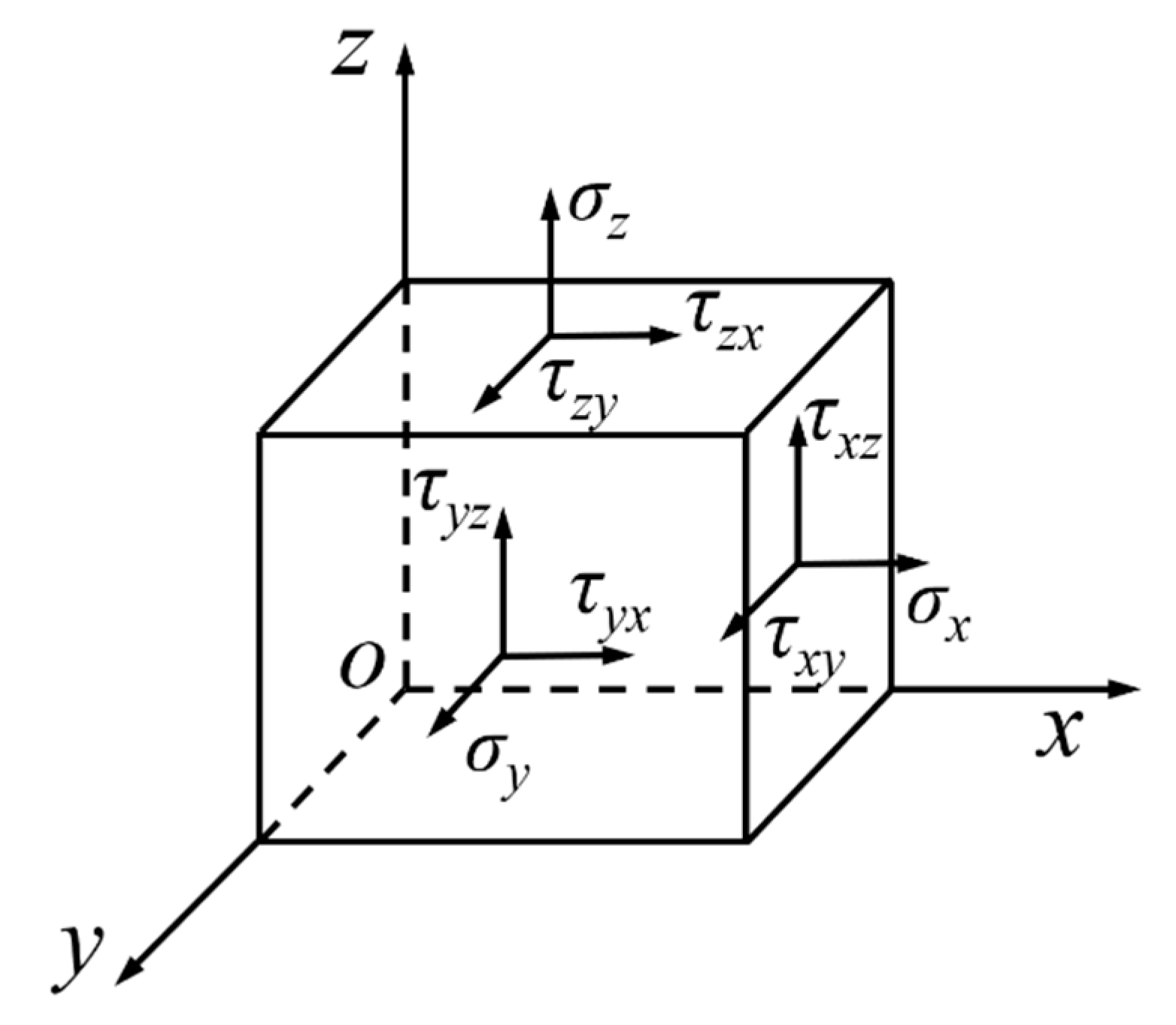
Under the action of the heat source, the internal material of the base metal produces force, as shown in Figure 1, due to expansion and contraction.
Construct the constitutive relationship [16] between strain and stress as shown in Equation (3) and obtain Equation (4) through differentiation.
where [E]el is the elastic matrix and is the stress.
The increase in thermal strain is related to the coefficient of linear expansion, and the coefficient of linear expansion of the base material changes with temperature.
where α0 is the initial linear expansion coefficient of the base metal.
In the plastic region of the base metal, the full strain increment [17] is shown in Equation (6).
where is the plastic strain increment.
According to the flow criterion, the plastic strain increment [18] can be described as:
where f is the yield function of the base metal, and P is defined as:
Construct the balance equation of the nodal displacement increment [19]:
where is the initial strain increment caused by temperature, [K]e is the element stiffness matrix, and they are respectively defined as:
According to Equations (10) and (11), the deformation increment can be expressed as:
When the weldment is welded, if there are welded joints on both sides of the weld seam, the boundary of the base metal of the seam will be constrained, and the deformation of the weld seam section is quite different from the free shrinkage boundary. The stiffness matrix needs to be modified according to the large number method. In Equation (11), if the initial strain vector is equal to the element in the ith row of the nodal displacement vector, that is, ri = δi, the main diagonal element kii of the stiffness matrix is multiplied by a large number 1015, and the element ri in the corresponding nodal displacement vector becomes ri∙kii∙1015. If ri ≠ δi, no processing is performed. The modified stiffness matrix is shown in Equation (13).
where [G] is the operation matrix for setting large numbers.
After the stiffness matrix is operated based on the method of setting large numbers, the node deformation increment under the constraint can be obtained, and it can be described as:
2.3. Calculation of Welding Deformation
According to the above derivation, when the welding boundary is not constrained, the welding deformation produced by the weld seam xi is as shown in Equation (15); when the welding boundary is constrained, the welding deformation produced by the weld seam xi is as shown in Equation (16).
where Ω is the total number of units along the weld axis, and Ie is the e-dimensional row vector with all 1 elements.
3. Construction of Welding Sequence Optimization Model for Arc Weld Seam
3.1. Construction of 3D Welding Model of Ship Arc Weld Weam
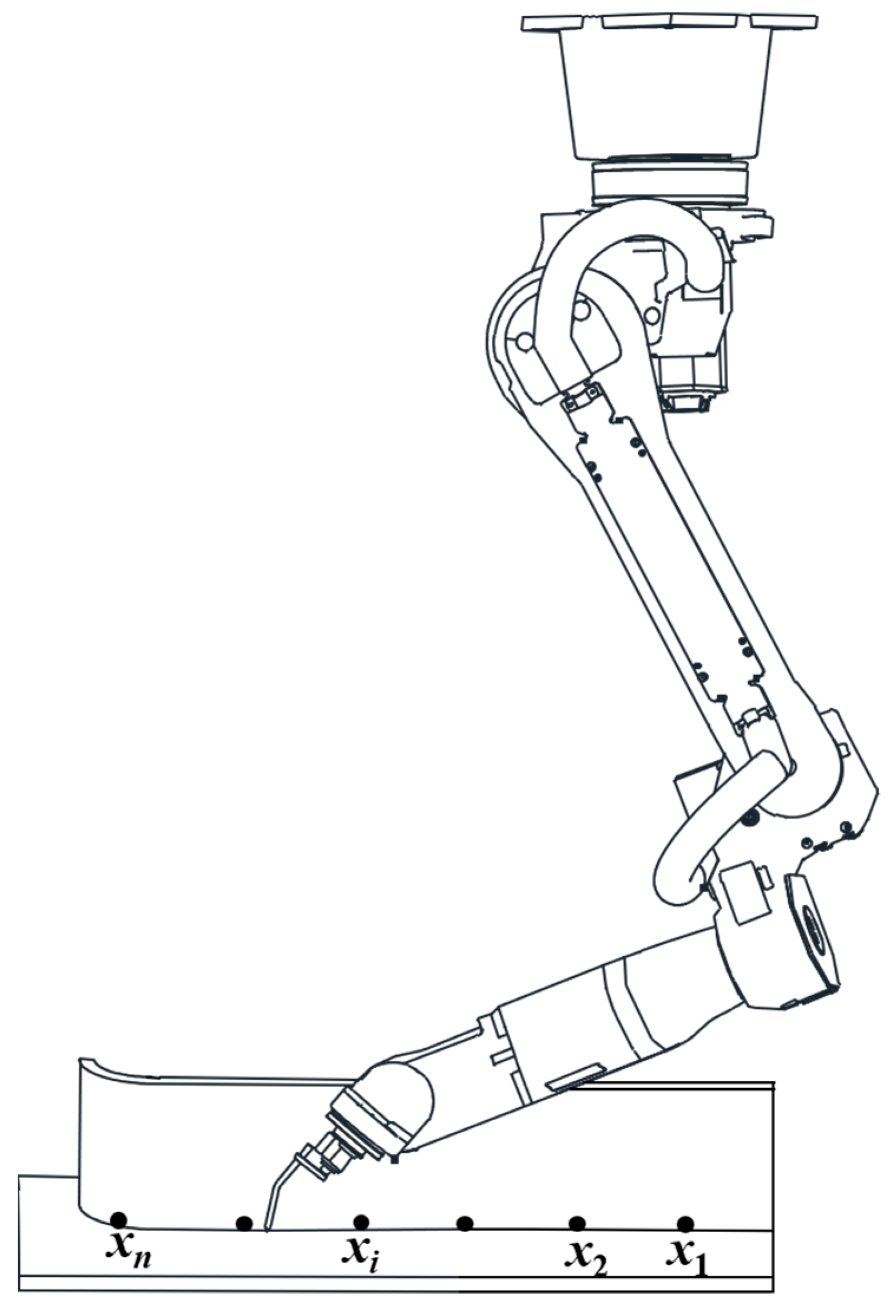
Ship welding robots are usually installed upside down [20], which can save working space and maximize their working radius. Figure 2 shows the three-dimensional welding model of the ship welding robot for the fillet arc welding. The arc weld seam is divided into n sections, and each section of the seam is represented by xi (i ∈ [1, n]).
3.2. Determination of the Objective Function for Welding Sequence Optimization
In the welding process, a different welding sequence selection will cause different welding deformation, which will affect the final welding quality. In order to achieve the optimal selection of welding sequence, the code xi (i ∈ [1, n]) of the weld seam is taken as a variable, and the minimization of the welding deformation is taken as the goal to construct the objective function for the welding sequence optimization, as shown in Equation (17).
where n is the total number of weld seams.
3.3. Construction of the Finite Element Model for Arc Weld Seam
In this paper, the base metal of the welded parts is Q345R steel, which is widely used in shipbuilding, and the changes in the mechanical properties of the base metal at different temperatures are shown in Table 1 [21]. In order to obtain the residual stress and deformation results of the base metal after welding, it is first necessary to divide the three-dimensional structure model into a finite element model. The welding models constructed in this paper include straight weld seams and arc weld seams. In view of the particularity of the arc weld seam, the sweep method is adopted to ensure that the size of each unit of the weld seam is uniform. Solid70 is selected as the grid unit for a multi-physics coupling solution [22]. During welding, because the area far away from the heat source is less affected by it, the mesh size of the area is divided to be larger, which helps to improve the solution efficiency. The transition area is divided by free grids to ensure the connectivity of the nodes. The bodies connected with the weld seam are all divided by free grids, and they are divided into 10 mm grids. The remaining part is the transition area and is divided into 20 mm grids. In addition, considering that the welded part is clamped by the fixture in the actual working condition, the movement and rotation of its bottom surface and the movement of one end surface in the horizontal direction are restricted when the finite element model is constructed.
4. Algorithm Design of Immune Optimization for Welding Sequence
4.1. Improved Immune Clonal Algorithm for Welding Sequence Optimization
Welding sequence optimization aimed at minimizing welding deformation is a multivariate combination optimization, and the number of welding sequences is exponentially related to the number of weld seams. Obviously, it is not only unrealistic to determine the welding sequence by the enumeration method, but it also cannot obtain the optimal solution. Therefore, an immune clonal optimization algorithm based on antibody similarity screening and steady-state adjustment (ICOABAS) [23] is introduced to improve the optimization performance of the welding sequence. The improved immune clonal algorithm mainly improves its search efficiency by screening high similarity antibodies in the welding sequence antibody group; at the same time, it improves its global optimization ability by vaccinating the population based on the median of high-quality vaccination. The ICOABAS includes antibody clonal operator , antibody mutation operator , antibody selection operator , population replenishment operator , vaccine extraction and vaccination operator . Assuming that the welded part has n weld seams, and any weld seam is coded with xi, the antibody in the immune algorithm can be expressed as a = [x1, x2, ⋯, xn]. In order to facilitate the design of the welding sequence optimization process based on ICOABAS, the basic description of each operator is given first, and the specific definitions can be found in [23].
4.1.1. Antibody Clonal Operator
Assuming that the population of the kth generation is A(k) = [a1(k), a2(k), ⋯, an(k)], ∀ i∈ [1, n], ai is a sequence of l-dimensional decimal numbers, and n is the population size, then the antibody clonal operator [23,24] can be described as:
where Ii is a l-dimensional unit row vector, and Bi(k) = [ai1(k), ai2(k), …, aiε(k)], ε is the clonal size, i ∈ [1, n]; If n is an odd number, n/2 is rounded to 0.
4.1.2. Antibody Mutation Operator
According to the mutation probability pm, a small perturbation is randomly applied to the antibody gene position. The antibody mutation operator [23] can be described as:
where , j ∈ [1, l]; ; rand() is the generating function of (0, 1) random numbers; χmax is the maximum threshold of the antibody gene locus.
4.1.3. Antibody Selection Operator
Antibody selection operator [23] is to realize the selection of dominant individuals of the population based on the evaluation of antibody incentives, that is:
where f(∙) is the solution function of antibody excitation based on antibody antigen affinity and antibody concentration [25], and can be described as:
where λ is the incentive coefficient of affinity, μ is the incentive coefficient of concentration, faff(∙) is the calculation function of antigen-antibody affinity, and fmsl is the calculation function of antibody concentration.
f(∙) = λfaff(∙) + μfmsl(∙)
4.1.4. Population Replenishment Operator
In order to avoid repeated calculations due to longer same gene fragments between antibodies, a population replenishment operator that can actively screen is designed in this paper, that is, antibodies are first compared to each other to obtain the same gene fragment length, and then, according to the length to determine whether to proceed replacement of new antibodies. The detailed flow of the operator can be found in [23].
4.1.5. Vaccine Extraction and Vaccination Operator
In order to avoid premature phenomena in algorithm optimization, the steady-state regulation mechanism of the human environment [26] is used for reference in ICOABAS. The human body water–salt balance is abstracted as the antibody population evenly distributed in the solution space, and the median is used to judge whether the population is evenly distributed. When antibodies spread unevenly, the optimal antibody is extracted and the antibody population is vaccinated, so that the antibodies in the antibody group are evenly distributed. The detailed vaccine extraction and vaccination process can be found in [23].
4.2. Immune Optimization Process of Welding Sequence
Step 1 Initialize the parameters of the immune algorithm: population size n, coding dimension l of antibody gene, maximum evolution generation kmax, mutation probability pm, affinity incentive coefficient λ, concentration incentive coefficient μ, similarity threshold Vt, clonal size ε, the maximum threshold χmax of an antibody gene locus, the minimum threshold χmin of antibody gene locus and other parameters, k ← 0;
Step 2 Randomly generate the initial welding sequence antibody population A(0) = {αi(0)|1 ≤ i ≤ n};
Step 3 Perform clonal and mutation operations on all antibodies in the population, based on ICOABAS;
- Step 3.1 Antibody clone A′(k) ← (A(k));
- Step 3.2 Antibody mutation A″(k) ← (A′(k));
Step 4 Thermal structure coupling calculation for all welding sequence antibodies based on Ansys finite element analysis program;
- Step 4.1 Each welding sequence antibody is extracted in the finite element analysis program;
- Step 4.2 Establish the finite element calculation model corresponding to each antibody, and generate an Ansys input execution file;
- Step 4.3 Perform thermal structure coupling calculation according to the execution file, and extract the maximum welding deformation value of the node;
Step 5 Calculate the antibody fitness value according to the maximum welding deformation value of all nodes;
Step 6 Perform antibody selection, population replenishment and vaccine extraction and inoculation operations for welding sequence antibodies;
- Step 6.1 Antibody selection A‴(k) ← (A″(k));
- Step 6.2 Population replenishment S(k) ← (A‴(k));
- Step 6.3 Perform vaccine extraction and inoculation, and get the next generation population A(k + 1) ← (S(k));
Step 7 Judge whether the termination conditions are met. If the algorithm does not iterate to the maximum evolution generation, return to step 3, otherwise, output the optimal welding sequence and exit the algorithm.
5. Optimization Test and Result Analysis of Welding Sequence
5.1. The Influence of Welding Sequence on Welding Deformation of A Typical Arc Welded Part
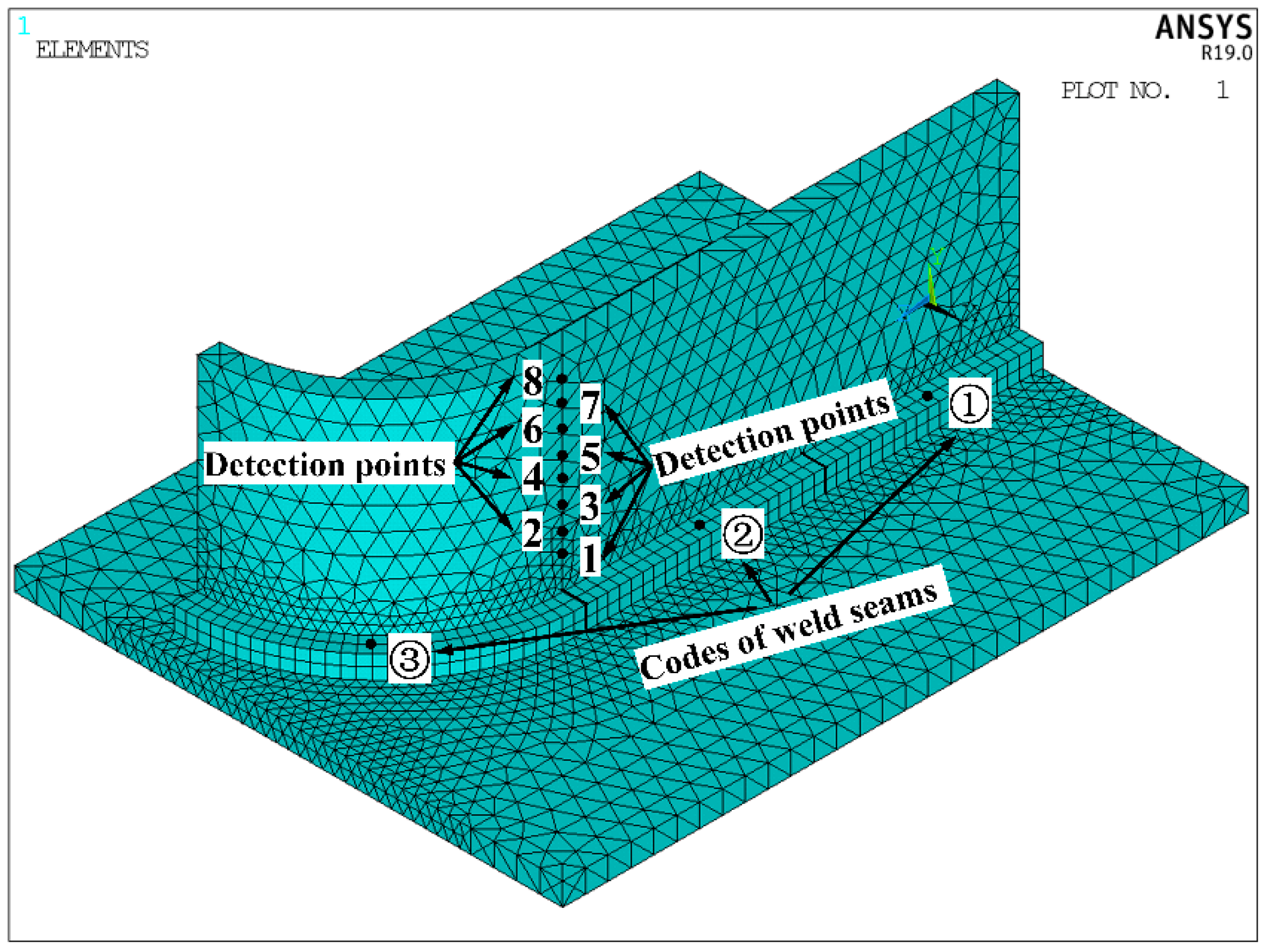
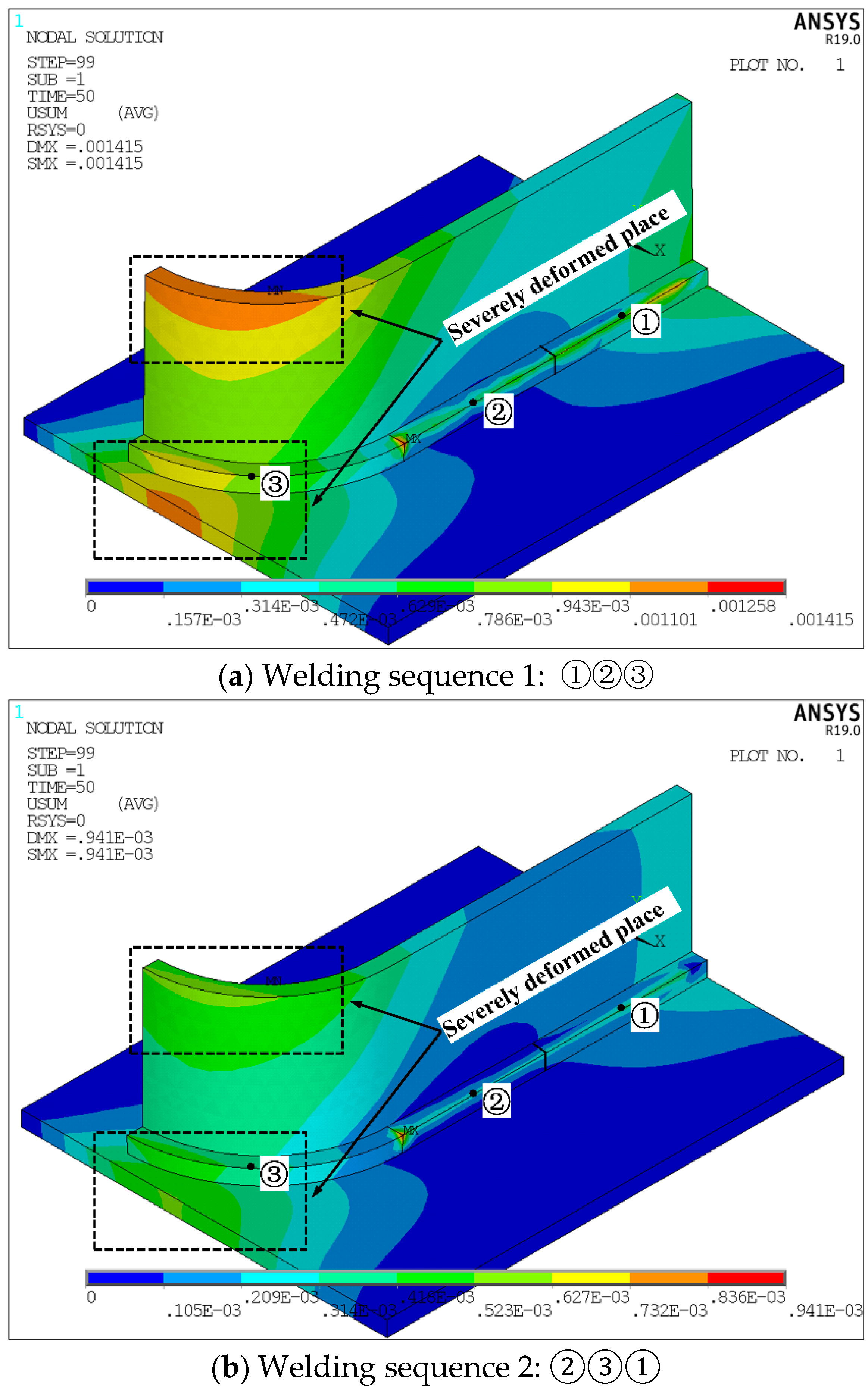
In order to verify the influence of the welding sequence on welding deformation, a typical arc welded part in Figure 2 is first analyzed in this paper [27]. As we all know, there are many types of welding deformation, including shrinkage deformation, angular deformation, bending deformation and twisting deformation, and many kinds of deformation are often mixed together. Since the objective optimization function in this paper is constructed based on shrinkage deformation, the subsequent optimization analysis is also mainly about shrinkage deformation. Figure 3 shows the finite element numerical calculation model of this typical arc welded part. Numbers 1–8 in the figure are welding deformation detection points, and the numbers ①②③ are the codes of three-segment weld seams. Figure 4 shows the deformation of the arc welded parts under different welding sequences. The welding sequence in Figure 4a is “①②③”, that is, the one-time welding is completed from the starting point along the weld seam to the endpoint. The welding sequence in Figure 4b is “②③①”, that is, the welding is carried out from the middle of the weld seam to both ends. From Figure 4, it can be seen that the welding deformation caused by welding sequence 1 is larger, and the gradient change of the welding deformation is more obvious. In addition, the deformation at the arc weld seam is more severe than that of the straight weld seam. After changing the welding sequence, the overall deformation of the welded part caused by welding sequence 2 is improved, and the transition of welding deformation at different positions is more relaxed. Table 2 shows the comparison of the welding deformation of the welded part caused by the two welding sequences. From the table, it can be seen that the maximum deformation caused by welding sequence 1 reached 1.415 mm, while the maximum deformation caused by welding sequence 2 is reduced to 0.941 mm. Therefore, different welding sequences have a greater impact on the deformation of the welded parts, which in turn affects the welding quality.
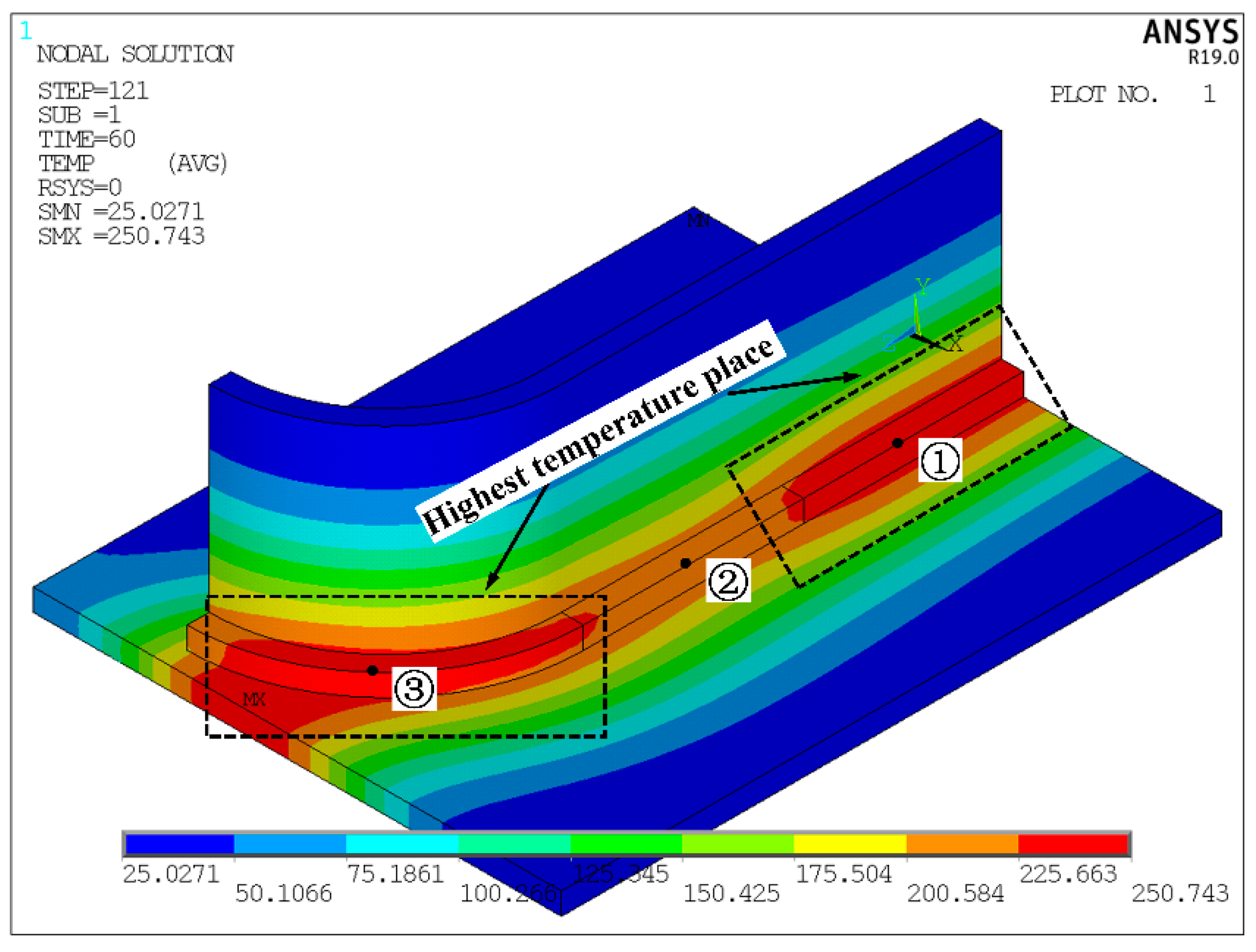
Figure 5 shows the temperature field at step 121 of the welded part caused by welding sequence 2. From the figure, it can be seen that the temperature gradient of the base metal in the vicinity of the weld seam has a large change, and the temperature gradually decreases as the distance from the weld increases. The heat transfer on the base metal conforms to the actual working conditions. Due to the heat input of the welding heat source, the welded part will eventually undergo thermal deformation.
5.2. The Influence of Welding Sequence on the Welding Deformation in Ship Middle Assembly
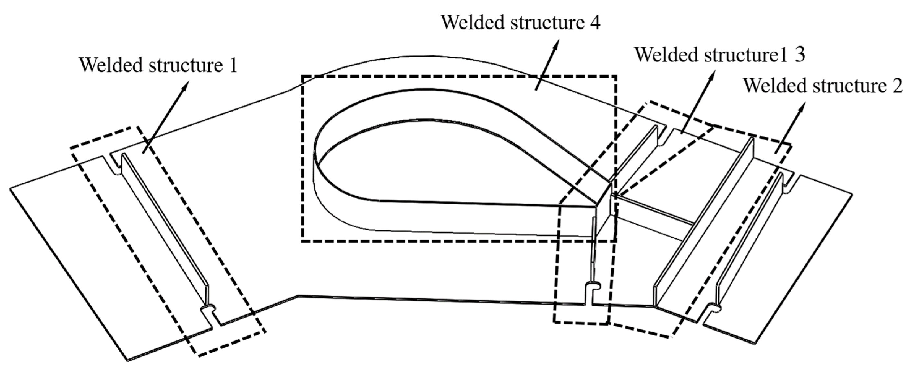
In order to further verify the influence of the welding sequence on the deformation of welded parts, numerical tests are carried out for a ship middle assembly, as shown in Figure 6. The assembly includes four welded structures, of which structure 4 is an arc welded part.
5.2.1. Division and Coding of Weld Seams
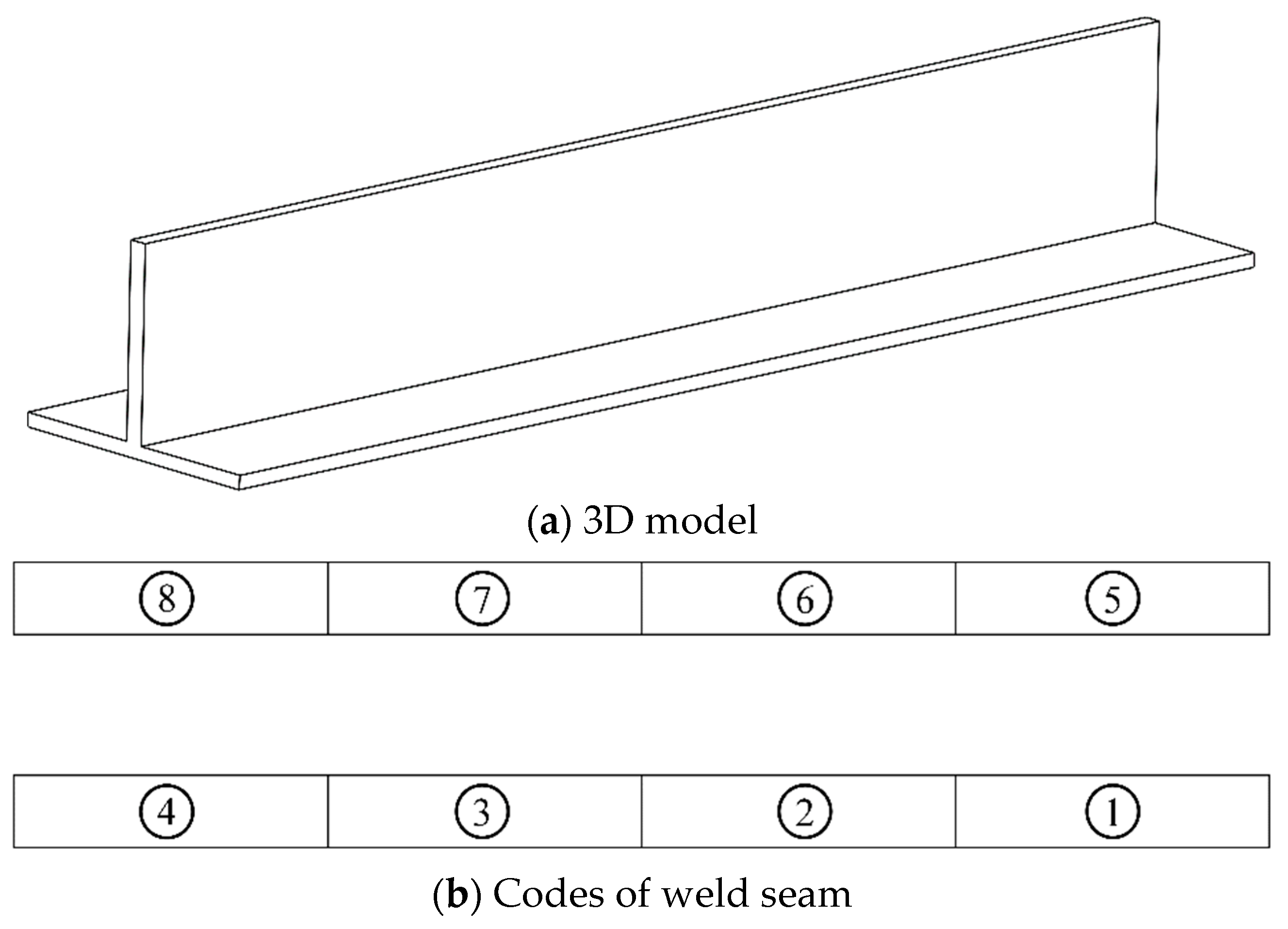
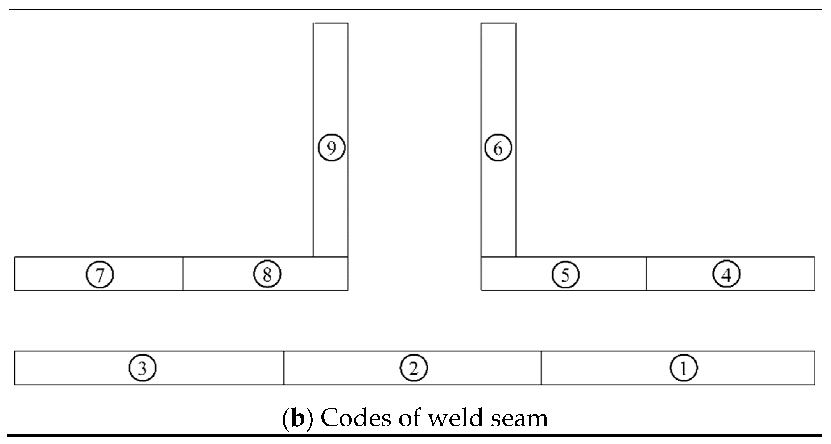
Since ship welded parts are generally thicker, double-sided welding is usually performed during welding [28]. In order to make the numerical simulation consistent with the actual welding, double-sided coding is carried out for the linear welded structures 1–3, and the arc welded part is single-sided coding because the area enclosed by it is empty. In the coding process, welds that are not continuous and whose length is less than 500 mm are coded as independent individuals, and welds that are longer than 500 mm are divided and numbered according to the length of 500 mm. The codes of the four welded structures in Figure 6 are shown in Figure 7, Figure 8, Figure 9 and Figure 10.
5.2.2. Test Result Analysis
In order to further verify the effectiveness and superiority of ICOABAS in the welding sequence optimization of the ship middle assembly, some numerical tests are carried out on a PC platform with an Intel Core i5-4200H CPU and 8 GB RAM, and the test results are compared with those of the immune genetic algorithm (IGA) [29], immune clonal algorithm (ICA) [30] and genetic algorithm (GA) [31]. The main parameters of IGA, ICA and GA come from their respective references. In view of the probabilistic search of intelligent optimization algorithms, 30 independent random tests are performed on the 4 optimization algorithms, respectively, and the maximum evolutionary generation is 50. The test results are shown in Table 3. From the overall optimization results, it can be seen that compared with the genetic algorithm, the immune clonal algorithm, and immune genetic algorithm for the four welded structures, the maximum deformation and average deformation of the welded parts caused by the welding sequence optimized by ICOABAS are the smallest, and the maximum welding deformations are respectively reduced by 3.1%, 4.0%, and 3.4%, and the average maximum welding deformations are respectively reduced by 3.5%, 5.5%, and 4.7%. This is mainly due to the median-based vaccination in the immune clonal algorithm, which improves the global immune optimization ability in welding sequence optimization. From the convergence generation, it can also be seen that compared with the other three algorithms, the value of ICOABAS is basically the smallest, and its convergence generation is reduced by 16.8%, 13.1%, and 14.5%, respectively. This is mainly due to the screening of antibodies with high similarity, which improves the optimization efficiency of the immune clonal algorithm. Thus, the proposed ICOABAS is not only effective in welding sequences but also has obvious advantages compared with other intelligent optimization algorithms. Next, the optimization results of the four intelligent algorithms are compared and analyzed in detail around each welded structure. For welded structure 1, the optimization results of the four algorithms all show that the welding deformation can be reduced by symmetrically welding from the middle position of the weld seam to both ends. Compared with the optimization results of ICA and IGA, the optimization results of ICOABAS and GA are better, and their optimal welding sequences avoid the continuous welding of adjacent welds. For welded structure 2, the optimization results of ICOABAS and IGA are close, and they are both better than the results of GA and ICA. From the optimization sequence, it can be seen that short weld seams should be welded before long weld seams. For welded structure 3, the optimization results of the four algorithms are relatively close, and the symmetrical welding of two weld seams can effectively reduce the welding deformation. For welded structure 4, it can be seen from the optimization results of the four algorithms that the optimization performance of ICOABAS is the strongest, while the performance of IGA is the worst. From the optimal welding sequence, it can be further found that for a weld seam with arc and straight sections coexisting, the arc weld should be welded first and then the straight weld, and the arc weld should be welded from the end first, which will help reduce the welding deformation.
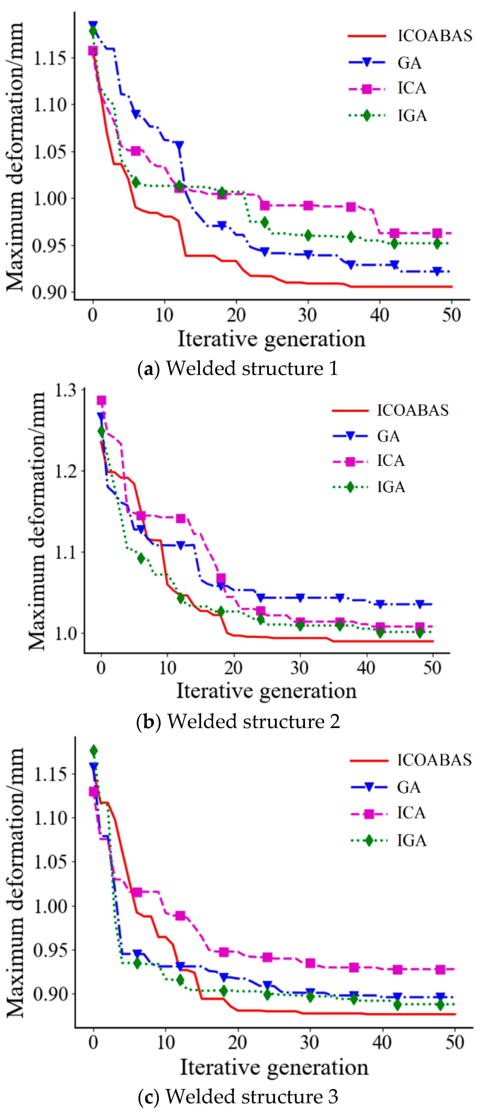
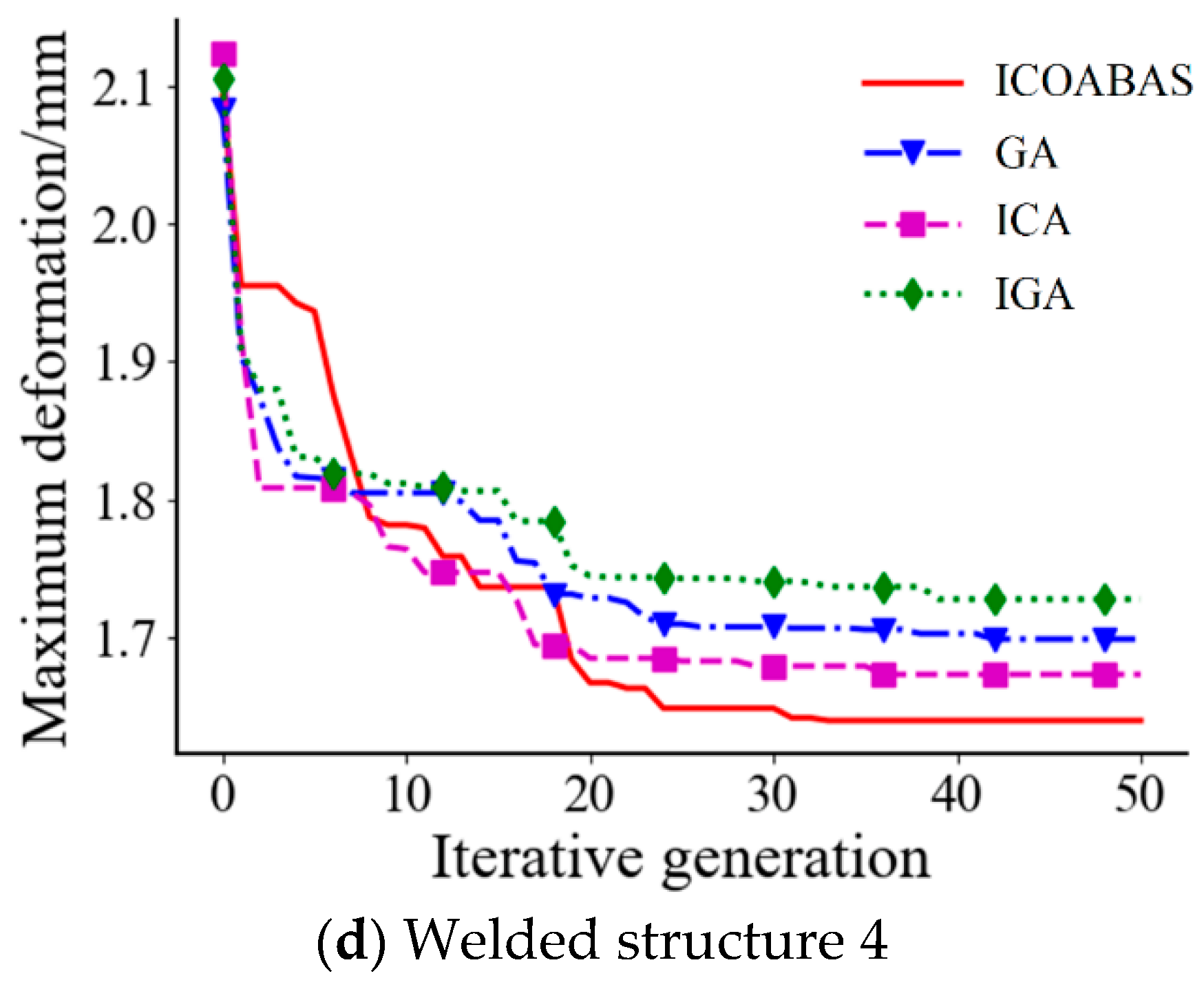
Figure 11 shows the evolution curves of the maximum deformation under the welding sequence optimized by the four intelligent algorithms in the four welded structures. From Figure 11, it can also be seen that the maximum deformation of the proposed ICOABAS is the smallest and the convergence speed is basically the fastest, which further verifies the effectiveness and superiority of ICOABAS.
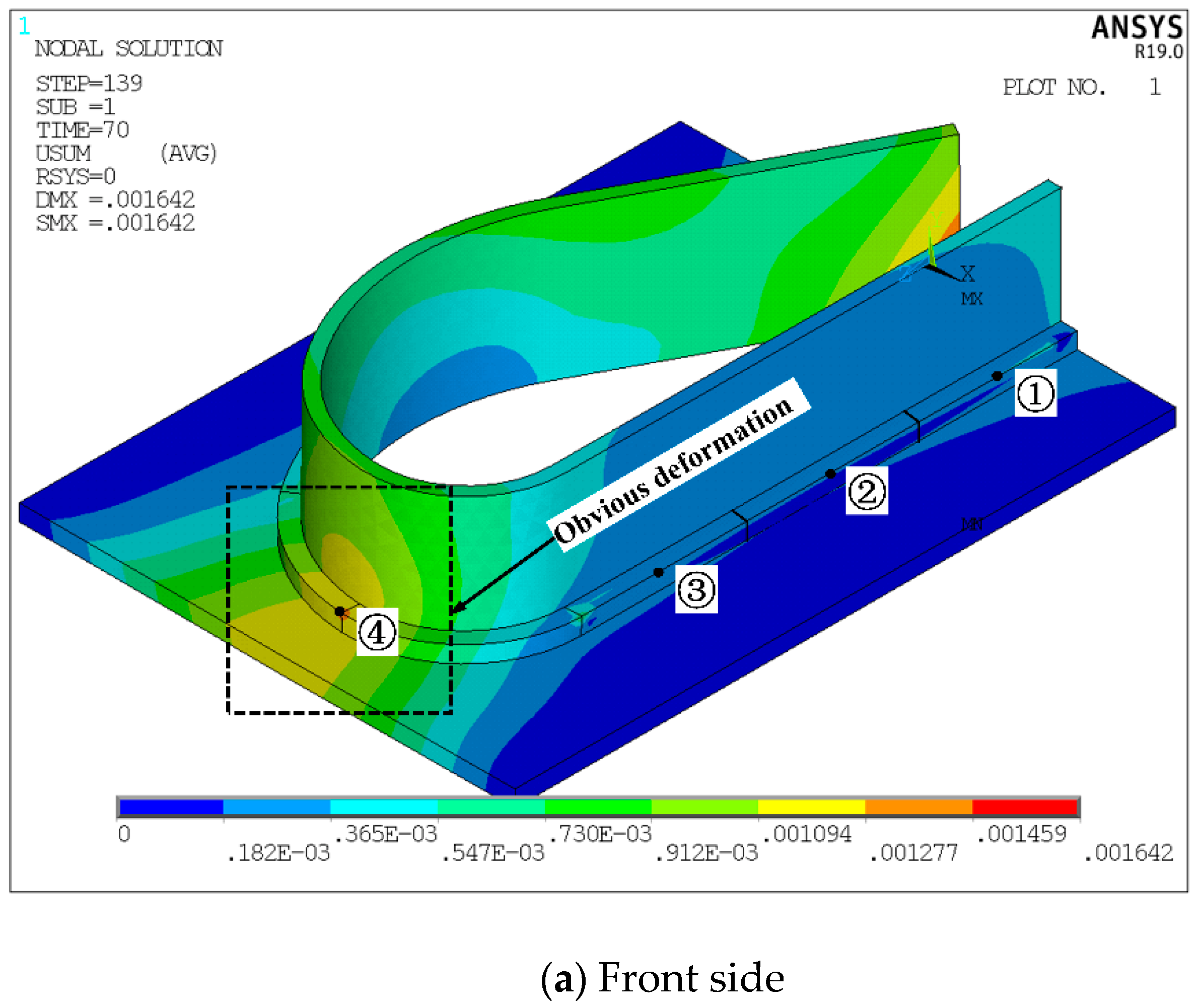
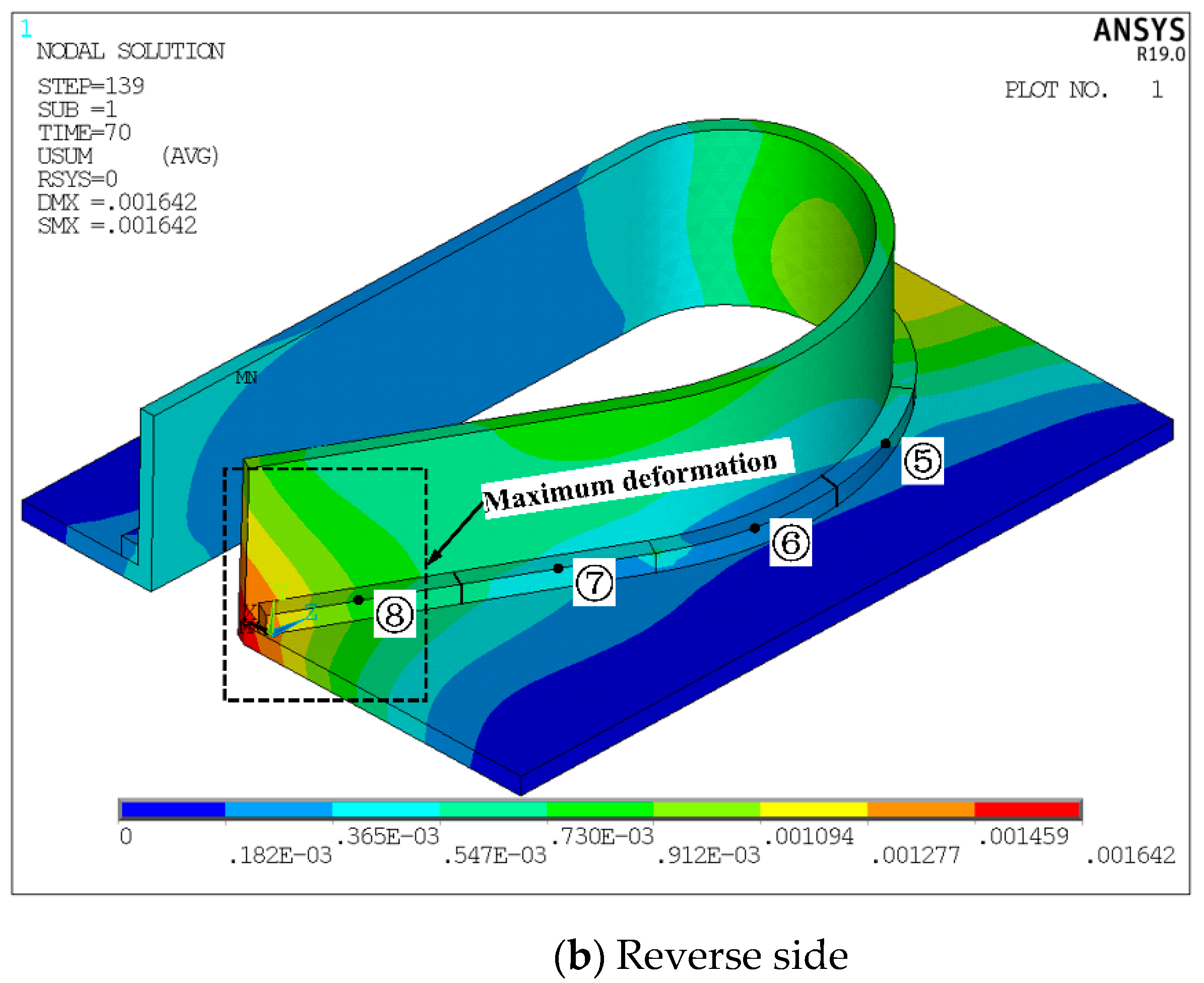
Taking welded structure 4 as an example, its total deformation cloud map under the optimal welding sequence “③⑤⑥④②⑦①⑧” is shown in Figure 12. From the figure, it can be seen that the welding deformation generated on the front straight weld side and the reverse arc weld side of structure 4 are quite different. The welding deformation on the front vertical plate of structure 4 is small, and there is no gradual change of deformation. Then, the deformation on the reverse vertical plate is more complicated, and a large deformation occurs on the vertical plate and gradually decreases toward the nearby area. The welding deformation peak of structure 4 appears at the end of the weld seam, that is, at the junction of the vertical plate and the bottom plate, and the deformation amount is 1.642 mm.
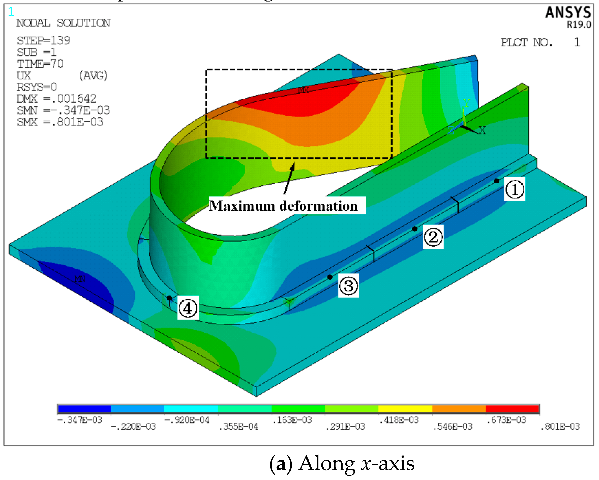
Figure 13 shows the cloud maps of the welded structure 4 along the x-axis and z-axis under the optimal welding sequence “③⑤⑥④②⑦①⑧”. From the figure, it can be seen that the positions of the transverse and longitudinal deformation peaks of structure 4 after welding are quite different. The deformation peak along the x-axis occurs at the edge of the vertical plate, that is, at the intersection of straight and arc weld seams. The deformation peaks along the z-axis appear on the base plate, that is, at the welding junction of the arc weld. It can be seen from the above that the welding of arc welds has an important influence on the distribution of transverse deformation and longitudinal deformation. Compared with arc welds, the changes of transverse deformation and longitudinal deformation at the position of straight welds are less severe.
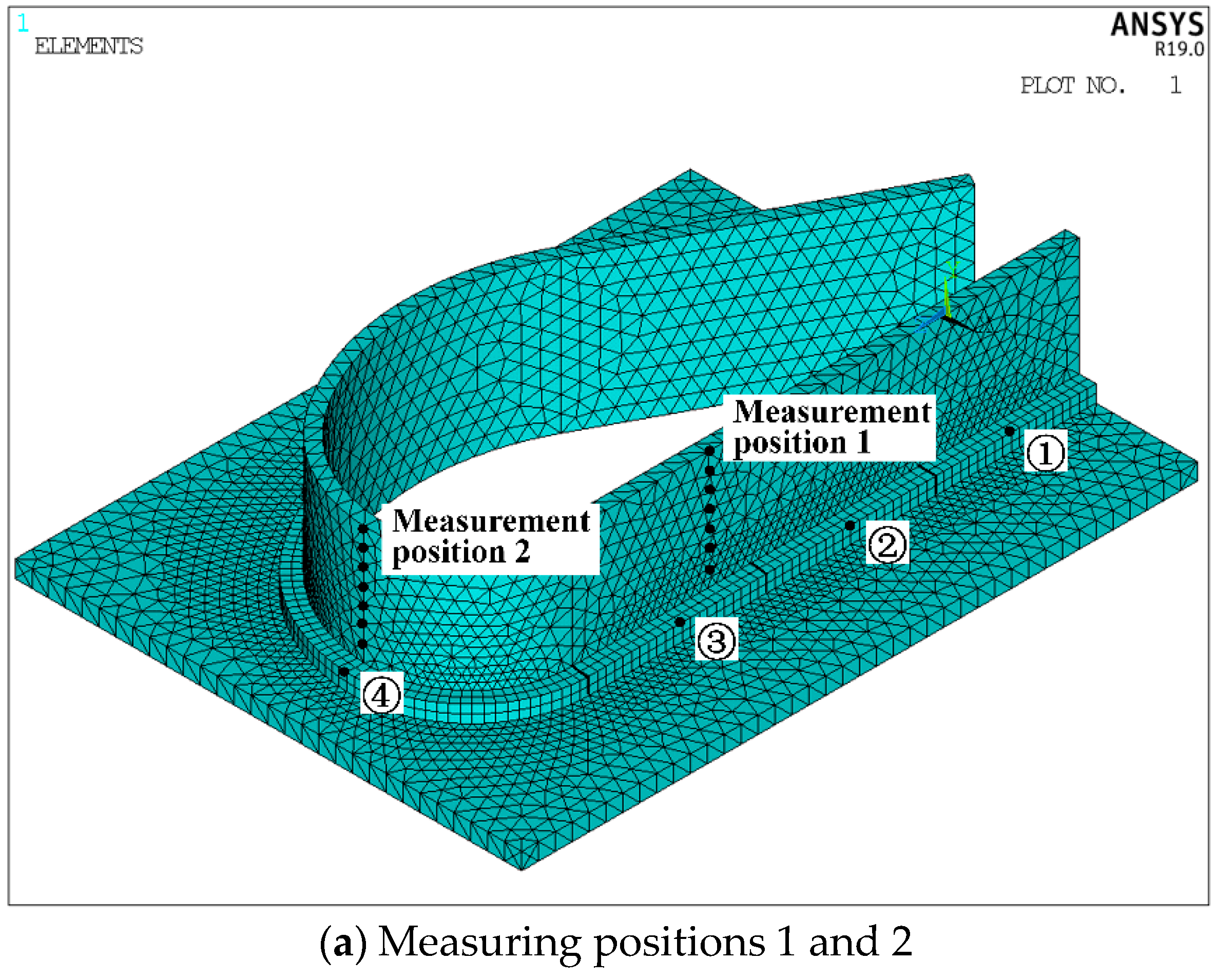
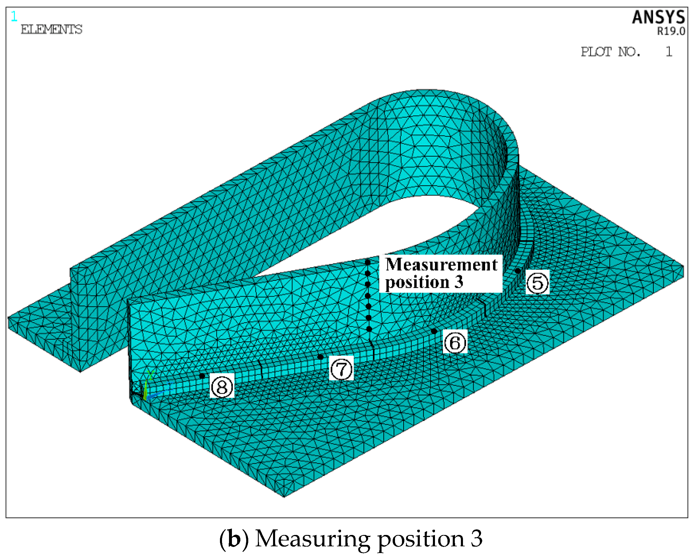
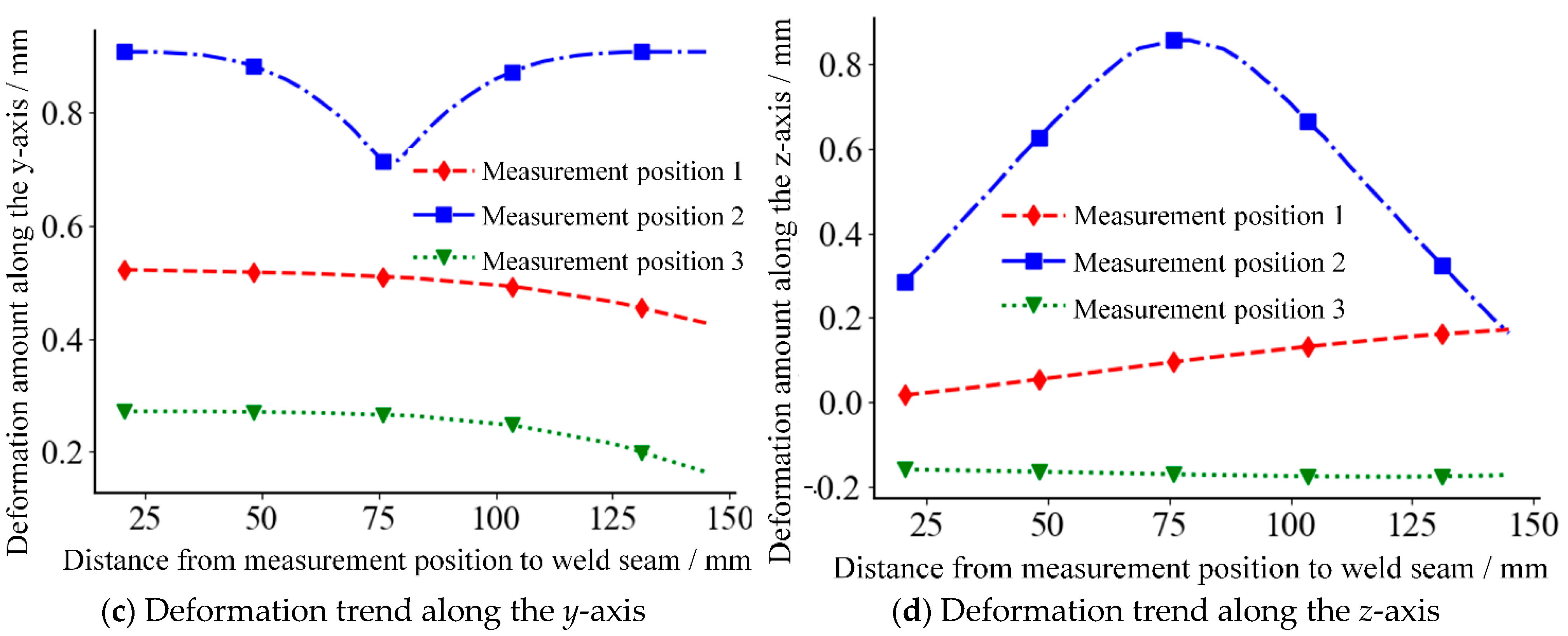
In order to explore the deformation and stress changes at the straight welds of structure 4 under the optimal welding sequence of “③⑤⑥④②⑦①⑧”, several nodes are selected on the vertical plate of structure 4 to form three measurement positions, as shown in Figure 14. The line of measurement position 1 is perpendicular to the straight weld; the line of measurement position 2 is perpendicular to the arc weld; the line of measurement position 3 is perpendicular to the transition position between the straight weld and the arc weld.
Figure 15 shows the deformation trend of structure 4 at three different measurement positions. From the figure, it can be seen that the deformation trend of the vertical plate of structure 4 at the measurement position 1 is quite different from that at the measurement positions 1 and 3, which is mainly reflected in the difference in the deformation amount on the middle, bottom and root of the vertical plate of structure 4. The deformation trend of measurement position 2 on the vertical plate is convex, and the deformation trend of measurement positions 1 and 3 are similar. With the increase in the distance between the measurement position and the weld seam, the deformation decreases. From Figure 15a, it can be seen that the deformation at the middle of the arc-shaped vertical plate on structure 4 is greater than the deformation at the top and bottom. The deformation of the straight vertical plate close to the weld seam is greater than that far from the weld seam. The deformation at measurement position 2 on the vertical plate exhibits the shape of peaks and valleys. The deformation trends along the y-axis and z-axis at measurement positions 1 and 3 are moderate, and the variation range is within 0.2 mm. However, the deformation change in measurement position 2 is more severe. The deformation fluctuation range in the y-axis direction exceeds 0.2 mm, and the range in the z-axis direction is about 0.6 mm.
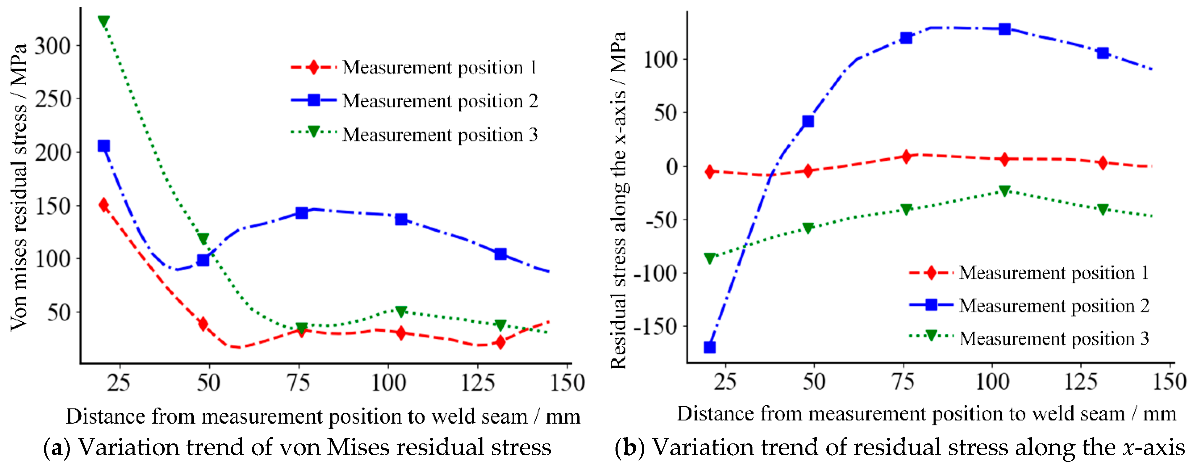
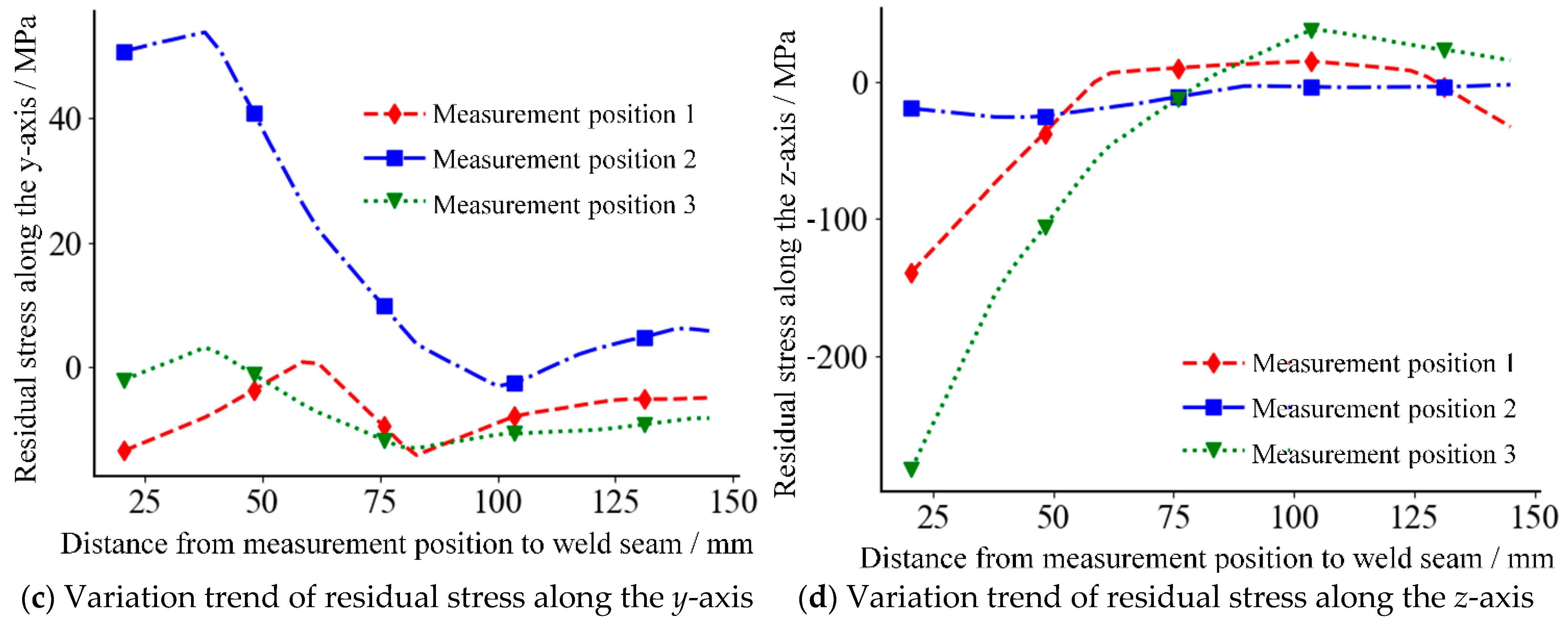
Figure 16 shows the residual stress variation of structure 4 at different measurement positions. From the figure, it can be seen that in the area within 50 mm from the weld seam on the vertical plate of structure 4, the residual stress at different measurement positions varies greatly. When the distance exceeds 50 mm, the difference in residual stress tends to be stable. From Figure 16a, it can be seen that von Mises residual stress of the nodes with a distance of more than 75 mm from the weld seam at measurement positions 1 and 3 is relatively close, but it is quite different from the residual stress of the nodes at measurement position 2 and has an average increase of 100 MPa. From Figure 16b, it can be seen that the residual stress of the nodes along the x-axis at measurement position 2 has a significantly different change trend from that at the measurement positions 1 and 3. The magnitude of residual stress also varies more, and the variation range exceeds 250 MPa. From Figure 16c, it can be seen that the residual stress along the y-axis direction at measurement positions 1 and 3 changes little, and the changing trend is also relatively close. The residual stress along the y-axis at measurement position 2 decreases greatly with the increase of the distance from the weld seam, but there is a small increase at 100 mm from the weld seam. From Figure 16d, it can be seen that the variation trends of residual stress along the z-axis at measurement positions 1 and 3 are similar. The residual stress along the z-axis direction at measurement position 2 has a small change, and with the increase of the distance from the weld seam, the magnitude of the stress is relatively stable.
6. Conclusions and Future Work
There are a large number of arc welded structures in ship construction. Different welding sequences will cause different welding deformations, and the deformation of welded parts will lead to problems, such as a lower structural strength of the ship and worse bearing capacity. Therefore, the immune algorithm-based welding sequence optimization in ship medium-small is proposed in this paper. The following conclusions can be drawn from the numerical tests and analyses:
- (1)
- On the basis of the basic theory of thermo-elastic-plastic finite element, the thermal deformation optimization model of the arc weld seam is established under the premise of considering the constraints on the boundary of the weldment during welding. By comparing the deformation of the weldments under different welding sequences, it can be found that the deformation of the weldments caused by different welding sequences is greatly different. For the overall structure test, the difference in the maximum deformation caused by different welding sequences is 0.474 mm, and the difference in the average deformation is 0.263 mm. For the test of the structure in the x-axis and z-axis directions, the difference in the average deformation is 0.188 mm and 0.140 mm, respectively. The poor welding sequence will make the deformation gradient of the weldment surface change more drastically.
- (2)
- The number of welding sequences of welded parts is exponentially related to the number of divided weld seams. In order to improve the selection quality and selection efficiency of welding sequences, on the basis of the constructed thermal deformation optimization model, the distributed intelligent immune algorithm is introduced to optimize the welding sequence globally, and then the welding deformation is reduced to a certain extent. The test results of four welded structures based on the proposed immune clonal algorithm demonstrates that the maximum deformation after optimization is reduced by 21.9%, 19.8%, 24.1%, and 21.7%, respectively.
- (3)
- By replacing the longest common gene fragments of antibodies, the population screening is realized, high similarity antibodies are removed, the diversity of the population is improved, and the solution efficiency is improved. Inspired by the automatic adjustment of human water–salt balance, the unbalanced antibodies are corrected based on the median property, and the population antibodies are evenly distributed in the solution space through vaccine extraction and vaccination, which is beneficial to the global search of the algorithm in the solution space and avoids the algorithm from falling into local minima. Compared with the other three intelligent algorithms, the improved immune optimization algorithm in this paper reduces the maximum welding deformation by 3.1%, 4.0%, and 3.4%, the average maximum welding deformation by 3.5%, 5.5%, and 4.7%, and the convergence generation by 16.8%, 13.1% and 14.5%, which verifies the effectiveness of the improved strategy of the proposed immune algorithm.
In this paper, a large number of numerical calculations and analyses have been carried out for the immune optimization of welding sequences in ship medium-small assemblies. Although the optimal welding sequence can be obtained based on the immune optimization algorithm, and the welding deformation and residual stress based on this are also significantly reduced, there is still a certain error between the numerical simulation and real welding conditions. The next step of the research is to mainly build an experimental platform and test the deformation of welded parts under different welding sequences, so as to further verify the effectiveness of the immune optimization of the welding sequence in this paper. In addition, the proposed immune clonal algorithm is a global, distributed, and parallel optimization algorithm. A large number of numerical tests have verified its powerful search capability and efficient search efficiency, so it can be transformed into applications, such as coating process optimization.
Author Contributions
Methodology, M.Y. and S.L.; validation, M.Y., H.S. and C.L.; original draft preparation, S.L. and Y.G.; writing, S.L. and Y.S. All authors have read and agreed to the published version of the manuscript.
Funding
This research was funded by the High-tech Ship Scientific Research Project from the Ministry of Industry and Information Technology ([2019]360), Qing Lan Project of Jiangsu Province, and the 2021 Industry-University Research Preresearch Fund Project of Zhangjiagang City (ZKCXY2138).
Institutional Review Board Statement
Not applicable.
Informed Consent Statement
Not applicable.
Data Availability Statement
Not applicable.
Conflicts of Interest
The authors declare no conflict of interest.
References
- Shao, Y.J.; Yan, J.; Yang, Y.C. The influence of welding process on stainless steel welding deformation. Weld. Technol. 2015, 44, 80–81. [Google Scholar] [CrossRef]
- Jesus, R.H.; Baidya, S.; Gengis, T.R.; David, B.B. Welding sequence optimization using artificial intelligence techniques, an overview. Int. J. Comput. Sci. Eng. 2016, 3, 90–95. [Google Scholar] [CrossRef] [Green Version]
- Liu, J.G.; Hou, Q.H.; Ding, F.S. Effect of welding sequence on welding distortion of large-sized thick plate structure. Mach. Des. Res. 2021, 37, 70–72. [Google Scholar] [CrossRef]
- Dong, W.C.; Lu, S.P. Influence of welding sequence on the distortion of TA15 titanium alloy panel. Aeronaut. Manuf. Technol. 2017, 4, 42–46. [Google Scholar] [CrossRef]
- Guo, P.C.; Cao, S.F.; Yi, J. Numerical simulation and sequence optimization on the welding process of aluminum alloy vehicle bumper. Automot Eng. 2017, 39, 915–921. [Google Scholar] [CrossRef]
- He, G.Z.; Wei, S.M.; Yan, Z.Q.; Yang, X.H. Optimization of the FSW sequence for metro vehicles aluminum alloy floor. Electr. Weld. Mach. 2018, 48, 99–103. [Google Scholar] [CrossRef]
- Khezri, V.; Yasari, E.; Panahi, M.; Khosravi, A. Hybrid artificial neural network–genetic algorithm-based technique to optimize a steady-state gas-to-liquids plant. Ind. Eng. Chem. Res. 2020, 59, 8674–8687. [Google Scholar] [CrossRef]
- Wani, I.; Sharma, A.; Kushvaha, V.; Madhushri, P.; Peng, L. Effect of ph, volatile content, and pyrolysis conditions on surface area and o/c and h/c ratios of biochar: Towards understanding performance of biochar using simplified approach. J. Hazard. Toxic Radioact. Waste 2020, 24, 15–19. [Google Scholar] [CrossRef]
- Sharma, A.; Kushvaha, V. Predictive modelling of fracture behaviour in silica-filled polymer composite subjected to impact with varying loading rates using artificial neural network. Eng. Fract. Mech. 2020, 239, 107328–107332. [Google Scholar] [CrossRef]
- Elesztos, P.; Janco, R.; Vostiar, V. Optimization of welding process using a genetic algorithm. Mech. Eng. 2018, 68, 17–24. [Google Scholar] [CrossRef] [Green Version]
- Zhang, Y.Y.; Zheng, C.H.; Gao, T.T.; Mao, Y.; Jiang, Y.; Xu, M. Microstructure and mechanical properties of titanium alloy plane curve butt welded joints. Hot Work. Technol. 2020, 49, 150–152. [Google Scholar] [CrossRef]
- Guo, Z.F.; Bai, R.X.; Lei, Z.K.; Jiang, H.; Zou, J.C.; Yan, C. Experimental and numerical investigation on ultimate strength of laser-welded stiffened plates considering welding deformation and residual stresses. Ocean Eng. 2021, 234, 109239. [Google Scholar] [CrossRef]
- Zhang, S.L.; Guo, Z.; Liu, D.; Li, Y.L. Analysis of temperature field of L type welding parts based on ANSYS. Automob. Appl. Technol. 2018, 14, 120–122. [Google Scholar] [CrossRef]
- Zou, J.S.; Luo, X.F.; Ji, Z.C.; Yan, K. Study on welding properties of copper alloy for warship propeller. J. Jiangsu Sci. Technol. 2006, 3, 81–84. [Google Scholar]
- Wang, W.C.; Wang, S.Y.; Yu, T.; Jiang, B. Finite element analysis of 45 steel in HSM based on thermo-elastic-plastic theory. Coal Mine Mach. 2013, 33, 124–125. [Google Scholar] [CrossRef]
- Yue, J.W.; Huang, X.J.; Zhao, L.M.; Kong, Q.M.; Chen, Y.; Wang, Z.F. Finite element method study on stress-strain relationship of site soil. Mech. Eng. 2021, 43, 921–932. [Google Scholar] [CrossRef]
- Wang, C.; Wu, C.B.; Shao, L.T. Development of elastic finite element model for predicting welding deformation based on artificial thermal strain method. J. Mech. Eng. 2022, 25, 1–9. Available online: http://kns.cnki.net/kcms/detail/11.2187.TH.20211102.1549.014.html (accessed on 25 February 2022).
- Liu, G.C.; Wang, C.; Song, Y.L.; Xue, P.J. Investigation of flow stress models for anisotropic materials. J. Huazhong Univ. Sci. Technol. 2018, 46, 45–49. [Google Scholar] [CrossRef]
- Li, G.; Ji, Y.Q. Geometric large deformation analysis for beam element based on the approximate woodbury formula. China Civ. Eng. J. 2021, 54, 47–56. [Google Scholar] [CrossRef]
- Zhang, Y.F.; Han, J.H.; Liu, J.P.; Shang, Z.D. Design of welding station for multi-axis coordinated robot. Mach. Des. Manuf. 2020, 5, 249–252. [Google Scholar]
- Qu, R.B.; Guo, Y.F.; Xu, S.K. Optimization analysis of welding sequence of ballast water filter cartridge support. MW Metal Form. 2021, 9, 74–77. [Google Scholar] [CrossRef]
- Zhao, K.Z.; Liu, J.J. Multiple Cross-laminated container floor temperature field based on ANSYS. Appl. Mech. Mater. 2014, 3306, 83–88. [Google Scholar] [CrossRef]
- Liu, S.D.; Tao, L.J.; Liu, C.; Gao, Y.Q.; Sun, H.W.; Yuan, M.X. Immune cloning optimization algorithm based on antibody similarity screening and steady-state adjustment. In Proceedings of the 3rd International Conference on Advanced Information Science and System, Sanya, China, 26–28 November 2021; pp. 355–359. Available online: https://camps.aptaracorp.com/AuthorDashboard/dashboard.html?key=0&val=68b639ba-5286-11ec-b613 (accessed on 2 March 2022).
- Wang, L.L.; Shen, Y.; Xu, Y.S.; Yuan, M.X. Clonal selection algorithm combining cloud model and reverse learning. Comput. Eng. Appl. 2021, 57, 68–74. [Google Scholar] [CrossRef]
- Meng, Y.F.; Wang, T.; Li, Z.X.; Cai, J.Y.; Zhu, S.; Han, C.H. Improved adaptive artificial immune algorithm for solving function optimizatioin problems. J. Beijing Univ. Aeronaut. Astronaut. 2021, 47, 894–903. [Google Scholar] [CrossRef]
- Zhang, X.Y.; Li, Y.Q.; Wei, Y.Y.; Cui, X.H.; Guan, Y.F. Metabolic nuclear receptors and regulation of water, salt and lipid metabolism. In Proceedings of the 12th National Academic Conference of Young Physiologists of the Chinese Physiological Society, Wuxi, China, 20 October 2017; Volume 15, pp. 31–32. Available online: https://kns.cnki.net/kcms/detail/detail.aspx?FileName=OGSC201710004018&DbName=CPFD2017 (accessed on 2 March 2022).
- Yuan, M.X.; Liu, S.D.; Sun, H.W.; Gao, Y.Q.; Dai, X.L.; Chen, W.B. FEM research on welding thermal deformation of copper alloy sheet and optimization of welding sequence. Coatings 2021, 11, 1287. [Google Scholar] [CrossRef]
- Tang, J.X.; Wu, M.X.; Shi, L.; Wu, C.S.; Yang, W.; Gao, S. Pure aluminum/T2 copper dissimilar metal double-sided friction stir weld formation and mechanical properties. Chin. J. Nonferr. Met. 2022, 41, 1–15. [Google Scholar]
- Zeng, S.Y. Optimization algorithm for power flow calculation of power system considering power spring. Int. J. Sci. 2020, 7, 23–28. [Google Scholar]
- Yang, W.X.; Chen, Z.; Li, C.J. Adaptive clone selection algorithm for function optimization. Appl. Mech. Mater. 2014, 3468, 2147–2150. [Google Scholar] [CrossRef]
- Qu, H.Y.; Cheng, S.N. A new neural network with genetic algorithm in searching nonlinear function extremum. J. Phys. Conf. Ser. 2021, 1732, 12085–12086. [Google Scholar] [CrossRef]
Figure 1.
The stress distribution of the heated surface of the base metal unit.

Figure 2.
Three-dimensional welding model of the arc weld seam.

Figure 3.
Finite element model of an arc weld seam.

Figure 4.
Deformation cloud map of the welded part under two welding sequences.

Figure 5.
The temperature field of the welded part at step 121 in welding sequence 2.

Figure 6.
A ship medium assembly.

Figure 7.
Weld seam coding of welded structure 1.

Figure 8.
Weld seam coding of welded structure 2.


Figure 9.
Weld seam coding of welded structure 3.

Figure 10.
Weld seam coding of four welded structure 4.


Figure 11.
Maximum deformation evolution curves of four algorithms in four structures.


Figure 12.
Total deformation cloud map of welded structure 4 under the optimal welding sequence.


Figure 13.
Welding deformation cloud map of welded structure 4 along the x-axis and z-axis under the optimal welding sequence.
Figure 13.
Welding deformation cloud map of welded structure 4 along the x-axis and z-axis under the optimal welding sequence.


Figure 14.
Schematic diagram of measurement positions.


Figure 15.
Deformation trend of welded structure 4 at different positions in the welding sequence of “③⑤⑥④②⑦①⑧”.
Figure 15.
Deformation trend of welded structure 4 at different positions in the welding sequence of “③⑤⑥④②⑦①⑧”.


Figure 16.
Stress variation trend of welded structure 4 at different positions in the welding sequence of “③⑤⑥④②⑦①⑧”.
Figure 16.
Stress variation trend of welded structure 4 at different positions in the welding sequence of “③⑤⑥④②⑦①⑧”.


Table 1.
Changes in the mechanical properties of the welding base metal at different temperatures [21].
Table 1.
Changes in the mechanical properties of the welding base metal at different temperatures [21].
| Temperature/°C | Yield Strength/MPa | Elastic Modulus/GPa | Poisson’s Ratio | Convection Coefficient/W∙(m2∙K)−1 |
| 25 | 345 | 206 | 0.28 | 23 |
| 250 | 270 | 187 | ||
| 500 | 220 | 150 | ||
| 750 | 160 | 120 | ||
| 1000 | 75 | 70 | ||
| 1500 | 20 | 10 | ||
| Temperature/°C | Linear expansion coefficient | Specific heat capacity/J∙(kg °C)−1 | Thermal conductivity/W∙(m∙K)−1 | |
| 25 | 1.30 × 10⁻⁵ | 460 | 44 | |
| 250 | 1.32 × 10⁻⁵ | 480 | 39 | |
| 500 | 1.39 × 10⁻⁵ | 530 | 33 | |
| 750 | 1.48 × 10⁻⁵ | 675 | 30 | |
| 1000 | 1.34 × 10⁻⁵ | 670 | 26 | |
| 1500 | 1.33 × 10⁻⁵ | 700 | 20 | |
Table 2.
Deformation comparison of the arc welded part.
| Welding Sequence | Maximum Deformation of the Whole Welded Part (mm) | Average Deformation of the Whole Welded Part (mm) | Average Deformation along the x-Axis (mm) | Average Deformation along the z-Axis (mm) |
|---|---|---|---|---|
| Welding sequence 1 | 1.415 | 1.135 | 0.620 | 0.573 |
| Welding sequence 2 | 0.941 | 0.872 | 0.432 | 0.433 |
Table 3.
Test results of four optimization algorithms on four welded structures.
| Algorithm | ICOABAS | GA | |
|---|---|---|---|
| Structure 1 | Maximum deformation | 0.906 | 0.922 |
| Average maximum deformation | 0.843 | 0.885 | |
| Convergence generation | 36 | 42 | |
| Optimal welding sequence | ②⑥③⑦ ①⑤④⑧ | ②⑦③⑥ ①⑤④⑧ | |
| Structure 2 | Maximum deformation | 0.990 | 1.035 |
| Average maximum deformation | 0.935 | 0.972 | |
| Convergence generation | 35 | 41 | |
| Optimal welding sequence | ⑤⑧②④ ⑦①③⑥⑨ | ②⑤⑧④ ⑦⑥⑨①③ | |
| Structure 3 | Maximum deformation | 0.876 | 0.896 |
| Average maximum deformation | 0.818 | 0.824 | |
| Convergence generation | 38 | 40 | |
| Optimal welding sequence | ③⑥②⑦ ①⑤④⑧ | ②⑥③⑦ ④①⑤⑧ | |
| Structure 4 | Maximum deformation | 1.639 | 1.698 |
| Average maximum deformation | 1.515 | 1.577 | |
| Convergence generation | 32 | 41 | |
| Optimal welding sequence | ③⑤⑥④ ②⑦①⑧ | ④③⑤⑥ ②⑦①⑧ | |
| Algorithm | ICA | IGA | |
| Structure 1 | Maximum deformation | 0.963 | 0.952 |
| Average maximum deformation | 0.894 | 0.891 | |
| Convergence generation | 40 | 41 | |
| Optimal welding sequence | ②③⑥⑦ ①⑤④⑧ | ⑥②③⑦ ①⑤④⑧ | |
| Structure 2 | Maximum deformation | 1.008 | 1.003 |
| Average maximum deformation | 0.968 | 0.939 | |
| Convergence generation | 41 | 40 | |
| Optimal welding sequence | ②⑤⑧④ ⑦③①⑥⑨ | ⑤⑧②④ ⑦⑥⑨①③ | |
| Structure 3 | Maximum deformation | 0.927 | 0.890 |
| Average maximum deformation | 0.862 | 0.836 | |
| Convergence generation | 40 | 41 | |
| Optimal welding sequence | ③⑥⑦② ①⑤④⑧ | ⑥②③⑦ ④⑤①⑧ | |
| Structure 4 | Maximum deformation | 1.673 | 1.727 |
| Average maximum deformation | 1.619 | 1.671 | |
| Convergence generation | 38 | 39 | |
| Optimal welding sequence | ③⑤④② ⑥①⑦⑧ | ③②⑤⑥ ④⑦①⑧ | |
Publisher’s Note: MDPI stays neutral with regard to jurisdictional claims in published maps and institutional affiliations. |
© 2022 by the authors. Licensee MDPI, Basel, Switzerland. This article is an open access article distributed under the terms and conditions of the Creative Commons Attribution (CC BY) license (https://creativecommons.org/licenses/by/4.0/).
Share and Cite
MDPI and ACS Style
Yuan, M.; Liu, S.; Gao, Y.; Sun, H.; Liu, C.; Shen, Y. Immune Optimization of Welding Sequence for Arc Weld Seams in Ship Medium-Small Assemblies. Coatings 2022, 12, 703. https://0-doi-org.brum.beds.ac.uk/10.3390/coatings12050703
AMA Style
Yuan M, Liu S, Gao Y, Sun H, Liu C, Shen Y. Immune Optimization of Welding Sequence for Arc Weld Seams in Ship Medium-Small Assemblies. Coatings. 2022; 12(5):703. https://0-doi-org.brum.beds.ac.uk/10.3390/coatings12050703
Chicago/Turabian StyleYuan, Mingxin, Suodong Liu, Yunqiang Gao, Hongwei Sun, Chao Liu, and Yi Shen. 2022. "Immune Optimization of Welding Sequence for Arc Weld Seams in Ship Medium-Small Assemblies" Coatings 12, no. 5: 703. https://0-doi-org.brum.beds.ac.uk/10.3390/coatings12050703
Note that from the first issue of 2016, this journal uses article numbers instead of page numbers. See further details here.