Article

Optimum Selection of Coated Piston Rings and Thrust Bearings in Mixed Lubrication for Different Lubricants Using Machine Learning

by
Anastasios Zavos
*,
Konstantinos P. Katsaros
and
Pantelis G. Nikolakopoulos
Machine Design Laboratory, Department of Mechanical Engineering and Aeronautics, University of Patras, 26504 Patras, Greece
*
Author to whom correspondence should be addressed.
Submission received: 20 April 2022 / Revised: 16 May 2022 / Accepted: 18 May 2022 / Published: 20 May 2022

Abstract

:
The purpose of this study is to build a parametric algorithm combining analytical results and Machine Learning in order to improve the tribological performance of coated piston rings and thrust bearings in mixed lubrication using different synthetic lubricants. The friction models for piston ring conjunction and pivoted pad thrust bearing consider the basic lubrication theory, the detailed contact geometry and the complete lubricant action for a wide range of speeds. The data produced from the analytical solutions are used as input for the training of regression models. The effect of TiN, TiAlN, CrN and DLC coatings on friction coefficient are investigated through multi-variable quadratic regression and support vector machine models. The optimum selection is considered when the minimum friction coefficient is predicted. Smooth TiN2 and TiAlN coatings seem to affect better the ring friction coefficient than rougher steel, TiN1 and CrN coatings using an uncoated or coated Nickel Nanocomposite (NNC) cylinder. Using an NNC cylinder for better durability, the friction coefficients were found to be higher by 31.3−58.8% for all the studied rings due to the rougher surface morphology. On the other hand, the results indicate that pads coated with DLC show lower friction coefficients compared to the common steel and TiAlN, CrN, and TiN applications. The multi-variable second-order polynomial regression models were demonstrated to be 1−6% more accurate than the quadratic support vector machine models in both tribological contacts.

1. Introduction

There is no doubt that tribological interactions have a dominant impact on engineering design. A good understanding of the generated friction for various tribological components is needed, owing to the increasing cost of fuel in conjunction with the environmental impacts. Piston rings and thrust bearings are two machine elements, where the tribologists have given attention in long-term efficiency and low cost of maintenance. Accordingly, these tribological contacts can be improved through their mechanical design and the properties of the fuel [1,2,3].
The piston group is the major contributor of parasitic losses, where the piston rings are an important part of this due to their excellent sealing performance and high friction losses under various loads. Therefore, different approaches have been used to improve fuel economy and durability. The selection of the appropriate coating is one of them. In the literature, first calculations on piston ring–liner contact were reported by Castleman [4] and Eilon et al. [5]. They used a 1D-Reynolds equation to predict lubricant film considering the effect of pressure, speed and lubricant viscosity. Later, in 1960, Furuhama [6] showed experimental results for piston ring conjunction using the direct measurement of friction using a floating liner. These results were compared with analytical predictions showing high friction at TDC reversal due to the mixed regime of lubrication. Furthermore, the effect of partially lubrication along the ring face width has been provided by Brown and Hamilton [7]. It was found that inlet starvation clearly influenced the predicted oil thickness. Ring–liner sealing performance is also affected by the ring contact face combined with cylinder liner geometry. In this topic, new studies were carried out regarding the effect of cylinder liner profile and its impact on the elastodynamics of the ring. Analysis of the ring complex motion because of the distorted bore has been presented by Ma et al. [8], showing their effects on oil film and friction, and by Tian et al. [9], who considered their effects on ring flutter and oil loss. In fact, the thin nature of the piston rings promotes transient dynamics conditions owing to the cylinder bore shape, which can reduce the ring sealing effect, as shown by Baker et al. [10]. With increased in-cylinder pressures and low speeds at the TDC zone, there would be high direct boundary interaction for thin piston rings as experimentally presented by Zavos et al. [11]. Therefore, a balance between contact friction and piston ring design should be sought. Taylor et al. [12] reported that ring frictional losses are predominant using low-viscosity lubricants when the engine speed is low at the traffic zone. This can be explained as the result of reduced minimum lubricant film. Knauder et al. [13] investigated the impact of a low viscosity SAE 5W30 lubricant on the piston group, crankshaft bearing and valve train for different IC engines. They found that the piston group and valve train efficiency is limited at high loads and low speeds, while the crankshaft bearing fuel efficiency can be clearly improved. To outcome potential risks that arise from reduced lubricant viscosity, different coatings are used in piston ring and cylinder surfaces. Recent investigations, experimental and numerical, have shown that some coatings can lead to decreased friction and lower wear [14,15,16,17]. The combination of coating topography and lubricant plays a specific role in boundary friction losses, where the effect of asperity interaction is predominant under a mixed regime of lubrication [18,19]. Therefore, an investigation of ring pack design and synthetic lubricant mechanisms should be mentioned for overall optimization in terms of fuel economy and engine durability. The above parameters were studied by Zhmud et al. [20] providing that the ring pack, cylinder liner surface finish and low viscosity lubricants are very important for the engine performance. This can be explained using appropriate CFD models [21,22] that combined the influence of the lubricant additives and the transient lubrication phenomena within the contact.
Another tribological couple of great interest is the pivoted pad thrust bearing with the rotor, which is designed to carry axial loads in dynamic conditions of rotating machinery. The principal of operation is based on the relative motion of the two surfaces and the convergent wedge shaped between them sucking the oil inside the contact. Such assemblies can be found in many applications. Industrial and naval applications are the most common of all, where the thrust bearings are forced to carry loads up to several hundred and in some cases even several thousand tons. The needs of modern economy and the new environmental standards leave no doubt that these bearings must operate at maximum load-carrying capacity with the minimum possible frictional losses. As a result, a variety of design improvements such as different surface profiles, texturing and pad surface coatings are carried out in order to improve their performance. To begin with, the shape of the oil film profile has a major impact on the load-carrying capacity of the bearing. After studying different one-dimensional film thickness profiles, Anandan et al. [23] showed that the polynomial profile is found to cause the maximum influence. Furthermore, Papadopoulos, Nikolakopoulos and Kaiktsis [24] studied the maximization of load-carrying capacity in sector pad thrust bearings with periodical partial trapezoidal dimples. The results showed that parallel thrust bearings textured by this type of dimples provide substantial load-carrying capacity levels. In 2005, Mahieux [25] presented his work regarding the influence of coating materials on the hydrodynamic behavior of thrust bearings. Clear evidence was provided that the nature of the material has a major impact on the bearing’s hydrodynamic behavior. The polymer coatings tested for this study were able to carry a large amount of load via surface deformations when the Babbitt-coated pad was forced to tilt. At the same time, although both polymer coatings (PTFE, PFA) had similar material properties, important differences were noted in the hydrodynamic behavior of the pads. Moreover, Jahanmir et al. [26] studied the load capacity and durability of H-DLC coated hydrodynamic thrust bearings. Through their work, it was shown that a fully wetted bearing can carry the highest amount of load compared to a half or partially wetted surface. At the same time, while tested in start–stop and impact conditions, the H-DLC-coated thrust pads showed both stability as well as the ability to endure more test cycles compared to the uncoated bearings. In addition, Katsaros et. al. [27] built a THD model of pivoted pad thrust bearing to compare Babbitt, PTFE and DLC coatings. It was shown that PTFE and DLC-coated pads provide lower friction in comparison to steel and Babbitt surfaces. To add to that, the DLC coating was chosen as the most suitable for thrust bearing applications when examining the effect of the coating on the flow and thermal fields of the bearing. Finally, the tribological performance of PEEK, PTFE and ATSP was examined by Nunez et al. [28] under boundary and mixed lubrication regimes at different aggressive experimental conditions. The results showed that these coatings and their blends provide low friction and high wear resistance when under different lubrication regimes and high contact pressures.
Nowadays, the rise in computing power and the massive network speeds led to rapid changes in technology and industry. The 4th industrial evolution or Industry 4.0 conceptualizes a wide range of applications such as the Internet of Things (IoT), Artificial Intelligence (AI) and Machine Learning (ML), which have been already applied in many technological areas including mechanical engineering. Machine Learning (ML) methods have been used in engineering for the solution of complex, non-linear, multi-dimensional problems that depend on a large amount of data [29]. For example, in tribology, Artificial Neural Network (ANN) techniques were used to predict mechanical properties [30] as well as friction and wear in lubricated contacts [31,32]. Furthermore, the fault diagnosis and life estimation of bearings has been studied by many authors utilizing ML. Kokkinidis and Nikolakopoulos [33] carried out a computer simulation of misaligned journal bearing using a neural network. They developed an Artificial Neural Network (ANN) model to train, test, and validate the performance parameters of journal bearing evaluated using the finite difference method (FDM). Ahmad et al. [34] presented a method combined a dimensionless health indicator (HI) to estimate the Residual Useful Life (RUL) of roller bearings using dynamic regression models. ML algorithms have also been used to predict acceptable operating conditions for different types of bearings. Katsaros and Nikolakopoulos [35] determined the effect of lubricant viscosity in pad thrust bearing tribological performance utilizing different regression models. The ML model built for this study compared three engine lubricants under various loads and speeds in order to predict optimal operating conditions. At the same time, Rossopoulos and Papadopoulos [36] created an analytics methodology based on ML in order to predict the performance of a marine journal bearing solving numerically the Reynolds equation in the hydrodynamic lubrication regime for different operating conditions. They tested different Machine Learning techniques considering the effect of shaft misalignment on lift-off speed. On the other hand, in the piston ring tribological problem, ML methods have been extensively used in friction and wear evaluation as well as manufacturing processes. Senatore et al. [37] found the lower average friction losses of piston ring–liner conjunction utilizing an Artificial Neural Network (ANN) model. Wołowiec-Korecka et al. [38] trained a neural network model for the creation of low-frictional coatings on piston ring surfaces. They built an industrial tool to optimize the nitriding process under reduced pressure in the piston ring manufacturing process. The current study is a continuation of the work from Katsaros and Nikolakopoulos on the combination of tribological analysis with Machine Learning techniques [35,39], adding the piston ring to the group of assemblies possible to be analyzed with the investigated Machine Learning models. The coating selection is also an add-in to the research. Eventually, the well-known tribo-contact will be included in the investigation with multiple variations in the input parameters of the study.
The aim of this study is to build an ML model based on regression algorithms in order to predict the optimum design parameters in terms of coating application and suitable lubricant selection for both piston ring and pad thrust bearing assemblies. A dataset of different operating conditions was generated by solving both tribological contacts for a variety of coatings, lubricants and velocities. Both lubrication problems were analyzed using time-efficient models, coating’s topography and the Greenwood and Tripp’s [40] approach for asperities interactions. This feature enables the designer to explore the influence of different parameters and ensures efficient comparisons of different machine learning solutions. Viscous and boundary friction were predicted, and the friction coefficient was determined in all studied cases. The predictive capabilities of the models with different regression methods were discussed by showing the best lubricant and coating selection for each component in mixed lubrication regime. The originality of this paper lies in the combination of tribological analysis models with Machine Learning techniques in order to identify and design tribo-contacts such as piston rings and pad thrust bearings in terms of optimum lubrication and coating selection, which is a topic that has not yet been tackled as a subject for research in a literature review.

2. Methodology

2.1. Piston Ring Lubrication Model

Analytical and experimental investigation of the piston ring surface is essential in order to find how the coating properties and lubricant oil react throughout the engine operating cycle. Gore et al. [16] presented some measurements of friction for coated surfaces in a sliding tribometer, and these predictions were compared using an analytical model showing strong agreement. An important consideration of this predictive method was the use of realistic asperity interactions within the contact upon coating properties with fast solution that were not very complex. This was also described by Zavos [18] modeling two coated thin piston rings with different topography. Therefore, this paper follows this time-efficient approach for the ring–liner conjunction in order to generate a sufficient dataset under different operating conditions and lubricant properties.
Figure 1 shows the rough profiles of the ring–liner conjunction including the typical contact parameters with corresponding generated pressures. A symmetric parabolic ring shape was used here as follows:
h s ( x ) = x 2 2 r
where r is the radius of the ring curvature. This eliminates the complexity of the analytical process, and the generated integrals can be solved algebraically as well. The ring curvature can be given as c = ( b 2 ) 2 2 r , where b is the ring face width.
Gore et al. [16], Zavos [18], and Mishra et al. [41] have shown that the generated pressures in the partially lubricated ring–liner contact are inadequate to cause any localized deformation. Therefore, the analysis can adopt an iso-viscous lubricant under isothermal conditions where the variation of film thickness can be described as:
h ( x ) = h o + h s ( x )
where h o is the minimum film and h s ( x ) is the ring profile. Equation (2) provides that the ring profile conforms perfect along the cylinder liner. This condition is ideal here as well as, in practice, the ring–liner conformance is partial and the ring flutters into the piston groove. Therefore, a two-dimensional analysis should be attained. This trend is a future direction of the current work.
The interface between the ring and liner has a thin film of lubricant where the lubrication states are changed from mixed to hydrodynamics during the piston stroke. Under a hydrodynamic regime of lubrication, the pressure distribution within the lubricated zone is calculated using Reynolds exit boundary conditions, ignoring squeeze film motion [42]. Fully flooded inlet conditions are also used. Figure 1 shows the flow conditions into the contact. The rise of the hydrodynamic pressure in the converging part of the ring is obvious in the figure. pin and pout are the gas pressures at the left and right sections of the piston ring. Thus, the total ring load can be defined as:
W t o t = W h + W c
where W h is the load due to lubricant film and W c is the load by asperities. The hydrodynamic load can be predicted as [42]:
W h = 2.45 r L ( μ U h o )
where U is the sliding velocity and μ is the dynamic viscosity. The stochastic model of Greenwood–Tripp [40] was used to predict the load by asperities. This generated load can be predicted as:
W c = 16 2 15 π ( ζ κ σ ) 2 σ κ E * A F 5 / 2 ( λ s )
where ζ and κ are the relative parameters according to the studied coated surfaces. σ is the combined standard deviation of roughness σ = σ r 2 + σ l 2 . λs considers the Stribeck lubricant film ratio. As for the statistical function of F5/2, a fifth-order polynomial curve was used, as it is mentioned by Teodorescu et al. [43]. Therefore, for λsλcr = 2.22:
F 5 / 2 ( λ s ) = 0.0046 λ s 5 + 0.0574 λ s 4 0.2958 λ s 3 + 0.7844 λ s 2 1.077 λ s + 0.6167 ;
and for λs > λcr = 2.22:
F 5 / 2 ( λ s ) = 0
where λcrit is the critical film ratio. To conclude the calculation of the asperities along the ring profile for which the lubricant film falls below the critical film ratio, it is important to find the actual asperities located close to the contact center. For this reason, the contact area A through Equation (5) should be altered for the symmetric parabolic ring. Thus, the integral term in Equation (5) can be expanded as [16,18]:
F 5 / 2 ( λ s ) d A = L 2 σ r { 2 λ s 3465 [ λ s ( λ s M 1244.62 ) + 2136.86 ] } λ ο λ c r
where λ ο = h o σ , λ c r = h c r σ = 2.22 and Μ = 1.449 λ s 3 + 22.099 λ s 2 146.421 λ s + 543.5892 .
The total ring friction is calculated by the viscous shear of lubricant film (viscous) and the direct contact by the asperities (boundary). This can be obtained as:
f t o t = f v + f b
where for the ring symmetric parabolic shape, the viscous friction is given as [16,18]:
f v = μ U L b 2 b 2 1 h ( x ) d x = 2 μ U L o b 2 1 h ( x ) d x = 2 μ U L 2 r h o tan 1 ( b 2 2 r h o )
and the boundary friction is [16,18]:
f b = τ o π 2 ( ζ κ σ ) 2 L 2 σ r { 2 λ s 3465 [ λ s ( λ s N 928.96 ) + 1733.53 ] } λ ο λ c r + μ a s p 16 2 15 π ( ζ κ σ ) 2 σ κ E * L 2 σ r { 2 λ s 3465 [ λ s ( λ s Μ 1244.62 ) + 2136.86 ] } λ ο λ c r
where the latter parameter of the real contact of the asperities for the studied ring is expressed as:
A c = π 2 ( ζ κ σ ) 2 F 2 ( λ s ) d A
where the integral term in Equation (13) can be obtained as [16,18]:
F 2 ( λ s ) d A = L 2 σ r { 2 λ s 3465 [ λ s ( λ s N 928.96 ) + 1733.53 ] } λ ο λ c r
where λ ο = h o σ , λ c r = h c r σ = 2.22 and N = 0.567 λ s 3 + 10.8185 λ s 2 85.536 λ s + 364.3794 . With regard to the coefficient of boundary shear strength, the surface roughness of the piston ring profile during the running-in process would affect this parameter, which can be captured using an Atomic Force Microscope (AFM) [44]. In this analysis, this value was constant for all running cases using the measured value of 0.22 [16]. Practically, a detailed investigation for all coated profiles would be required in the next work.

2.2. Thrust Bearing Lubrication Model

The hydrodynamic lubrication analysis of the pad thrust bearing for this study is based on the assumption that the flow of the lubricant is considered to be laminar and isothermal. The lubricant is assumed to be Newtonian, iso-viscous and incompressible. The minimum pressure value developed inside the film is assumed to be above the vapor pressure of the lubricant; thus, no cavitation effects are taken into consideration. Furthermore, the bearing’s surface deformations due to hydrodynamic and thermal loads are assumed to “forbid” the lubricant from escaping the conjunction. According to Aurelian et al. [45], slip can occur when the solid surface is smooth enough, and the oil is under relatively high shear stress. As a result, the no-slip assumption is taken into consideration for the fluid film that obtains the same velocity as the solid surface (rotor) that it comes into contact with. A schematic of the pivoted pad thrust bearing is shown in Figure 2.
In order to calculate the pressure distribution over the pad’s surface, the infinite linear pad bearing approach [46] is taken into consideration. Thus, the 1-D Reynolds equation is integrated over the pad’s surface. The film is expressed as a function of x:
h = f ( x ) = h 0 ( 1 + K x B )
where K is defined as the convergence ratio:
K = h 1 h 0 h 0
After the integration of the 1-D Reynolds equation over the surface of the pad, the pressure distribution is expressed as a function of the film thickness h:
p = 6 U μ Β K h 0 ( 1 h + h 0 h 2 ( K + 1 ) ( K + 2 ) + 1 h 0 ( K + 2 ) )
In order to calculate the load-carrying capacity of the pad, the pressure is then integrated over its surface:
W h = 6 U μ L B 2 K 2 h 0 2 ( ln ( K + 1 ) + 2 K K + 2 )
The calculation of the corresponding viscous friction force is based on the integration of the shear stress: τ = η d d z ( ( z 2 z h 2 μ ) p x U z h + U ) over the pad’s surface:
f v = U μ L B h 0 ( 6 K + 2 4 ln ( K + 1 ) K )
When the film thickness of the lubricant becomes very thin, then the asperities of the two surfaces (pad and rotor) come in contact with each other, and the total load-carrying capacity of the pad is directly affected by the load of the asperities. The stochastic model of Greenwood–Tripp [40] is used to predict this load. As a result, the total load-carrying capacity of the pad is also calculated from Equation (3).
Moreover, the contact of the asperities has an additional influence on the pad’s friction force. The total friction force is also a sum of the viscous friction and the boundary friction as already described in Equation (9). For the calculation of the boundary friction, the asperities load W c and the contact area due to direct asperities contact A c need to be taken into consideration:
f b = τ 0 A c + μ a s p W c
where τ 0 and μ a s p are the Eyring shear stress and the coefficient of boundary shear strength, accordingly.
The contact area due to direct asperities contact is predicted as follows:
A c = π 2 ( ζ β σ ) 2 A F 2 ( λ s )
As mentioned above, ζ and β are parameters correlated to the studied coated surface and σ corresponds to the equivalent of the roughness standard deviation for the pad and the rotor surfaces ( σ = σ p 2 + σ r o t 2 ) . The statistical Gaussian distribution of asperities is also assumed to be a 5th-order polynomial function of the Stribeck lubricant film ratio [43].
F 2 ( λ s ) = 0.0018 λ s 5 + 0.0281 λ s 4 0.1728 λ s 3 + 0.5258 λ s 2 0.8043 λ + 0.5003   f o r   λ s λ c r i t
and
F 2 ( λ s ) = 0   f o r   λ s > λ c r i t
The functions F5/2 and F2 represent the statistical manner of interactions for the deformed asperities as the one surface approaches the other. In order to improve the accuracy of the model for a specific pair of surfaces, the corresponding parameters must be defined. The parameters; κ, σ, β and ζ are usually determined by several metrology systems. Furthermore, in order to correctly apply the assumption of a Gaussian distribution for peak heights, the standard deviation and mean of the peak heights are needed. The functions F5/2 and F2 as well as the roughness parameters determine the possible number of asperities that are been penetrated at a given surface segment and the extent of their deformation. To add to that the different apparent areas shown in Equations (12) and (20) will lead to different results for the same material and operational conditions for the two examined tribo pairs.

2.3. Solution of the Analytical Methods

For both the piston ring and the pad bearing tribo-contacts, at any load conditions, the contact reaction must reach the applied load. This is achieved using the following criterion for each sliding velocity:
Σ = | F W t o t | F 0.1 %
If the criterion is not met, then the minimum film is modified as follows:
h o n + 1 = ( 1 + ε Σ ) h o n , n 1  
where n is an iteration counter and ε is the damping coefficient with the value of 0.15. The latter parameter is used for solution stability and fast convergence. When the convergence criterion is satisfied, the total friction is been calculated. For this analysis, the process is repeated for all studied piston rings and cylinder liners as well as pivoted pad thrust bearings. The analytical solution of the conjunctions is illustrated and summarized in Figure 3.
The algorithm begins with the values of the input parameters: lubricant viscosity, movement velocity, external applied load, and initial minimum film thickness. Then, the hydrodynamic lubrication problem is solved, and the corresponding load is calculated for the conjunction. At the same time, the additional load caused by the asperities contact is also calculated and added in the total load of the mechanism. In the next step, the balance between the external and the total load is checked. If there is a difference higher than the criteria (1 × 10⁻³), then the algorithm goes back to the input of minimum film thickness and updates the value. The process is repeated until the convergence criterion is met. For the last step, the final minimum film thickness, the viscous and boundary friction as well as the coefficient of friction are being calculated for the tribo-contact.

2.4. Lubricant Properties

Six types of lubricants are examined in this study. For the case of the piston ring–liner contact, three engine oils SAE 15W40, SAE 5W30 and SAE 0W20 are studied, while for the case of the pivoted pad thrust bearing, three different lubricants are also examined: a mono-grade oil SAE 30, a multi-grade oil SAE 10W40 and a bio-lubricant AWS100. Taylor et al. [12] and Katsaros et al. [35] described the rheological properties of these lubricants, particularly for tribo-contacts such as piston rings and pad thrust bearings. The effective lubricant viscosity through the average lubricant temperature is predicted using the Vogel equation [47]:
μ ( θ α v ) = k e x p ( θ 1 θ 2 + θ a v )
where k, θ1 and θ2 are the parameters of each oil, and θav is the average temperature.
Table 1 shows the input parameters of the Vogel expression and the corresponding dynamic viscosities at 120 °C. This temperature corresponds to warm conditions according to the New European Drive Cycle (NEDC) [48].

3. Machine Learning Techniques

Regression models are popular in Machine Learning applications mainly because they are simple to use, interpret and relatively accurate in predicting the desired values. Linear and polynomial regression models have been reviewed by Maulud et al. [49] as some of the most common and comprehensive statistical and Machine Learning algorithms. Furthermore, over the last few years, regression models have been chosen for a wide range of engineering applications such as prognosis of a wind turbine gearbox bearing remaining useful life [50], lubrication regime classification of hydrodynamic journal bearings [51] as well as tilting-pad thrust bearings hydrodynamic lubrication analysis for various operating conditions and lubricants [35,39]. The model used in this study in order to describe the relationship between the predictors and the response values is the multi-variable, 2nd-order polynomial regression based on the least squares methodology in which the sum of the squares of the residuals needs to be minimized.
As described in [35], all the data obtained from the lubrication models of the piston ring and the pad bearing create a set of n-observations that lead to a system of n-equations which in matrix form is generated as follows:
Y = [ y 1 y 2 y n ] = [ 1 x 11 x 21 x 11 2 x 11 x 21 x 21 2 1 x 12 x 22 x 12 2 x 12 x 22 x 22 2 1 x 1 n x 2 n x 1 n 2 x 1 n x 2 n x 2 n 2 ] [ β 0 β 1 β 2 β 03 β 4 β 5 ]
Or
Y = X B
where y i represents the dependant variable (or the response values), x i j are the independent variables (or the predictors) and β i ,   i = 0 5 represent the constants that derive from the solution of the above equation, with β 0 being the y-intecept of the polynomial surface and β i ,   i = 1 5 being the coresponding slopes. In this specific model, y represents the coefficient of friction, x 1 j represents the sliding velocity of the piston ring or the rotor of the pad (m/s), and x 2 j represents the young modulus of each coating applied for testing (GPa).
In order to determine the accuracy of the model to predict the response values, the coefficient of determination R 2 is calculated in each case:
R 2 = 1 1 n ( y y ^ ) 2 1 n ( y y ¯ ) 2
where y represents the values that derive from the analytical solutions, y ^ represents the predicted values and y ¯ is the mean of the true (analytical) values.
The standard error of the estimate has also been taken into consideration in the discussion of the results in terms of average deviation from the observations:
S = Σ ( y y ^ ) 2 / n  
For comparison purposes, Support Vector Machine Quadratic Regression models are trained using the polynomial kernel function for the same datasets:
( X , Y ) = ( c + X T Y ) 2  
All models were trained with 80% of the data from the dataset, and a cross-validation procedure was applied for 5 randomly chosen partitions of the original datasets. Experimental data were used for the validation of the ML model as shown in [35].

4. Results and Discussion

4.1. Input Data for the Piston Ring and the Thrust Bearing Analysis

Table 2 presents the piston ring contact parameters with operating conditions of this analysis such as (average) lubricant temperature, sliding velocity and applied load. A normal load of 60 N was applied as well as the sliding speed, which varied in the range of 0.5 to 5 m/s. These conditions were chosen to maintain a thin lubricant film when the mixed and hydrodynamic regimes of lubrication were expected, as a thin piston ring moved during the power stroke for a light motor engine [11].
For the case of the pivoted pad thrust bearing, the parameters from the experimental bearing tested from Bielec and Leopord [52] were taken into consideration. In order to maintain a thin lubricant film and a bearing that is studied in mixed and hydrodynamic lubrication regimes, the external applied load was assumed to be 7000 N, and the rotating velocities were simulated in the area of a theoretical start or shut down conditions from 100 to 1000 rpm (sliding velocities from 0.5 to 5 m/s). The main modeling parameters for the pivoted pad are summarized in Table 3.
Table 4 and Table 5 summarize the main coating properties including the roughness parameters of the piston ring and the cylinder liner surfaces, respectively, which are investigated in this study. The reference is a steel piston ring with an aluminum (uncoated) cylinder bore. The properties of CrN, TiN1, TiN2 and TiAlN coatings on the ring surface are also given. The data of CrN and TiN1 coatings were used by Zavos [18]. In the case of other coatings, TiN2 and TiAlN, the main properties were obtained by Wróblewski et al. [17]. Additionally, in contrast to a regular uncoated aluminum cylinder liner, a Nickel Nanocomposite (NNC) cylinder liner was also applied using data by Dolatabadi et al. [15], in order to determine and compare the coefficient of friction with the coated piston rings.
Table 6 summarizes the main material properties used in this study including the roughness parameters of the coated pad surfaces. A steel rotor of σ = 1.7 μm is examined in contact with pivoted pads of steel, TiN, CrN TiAlN and DLC coatings. The average roughness Ra is used for the studied tribo-contacts. The terms ζκσ and σ/κ are obtained using the basic theory by Arcoumanis et al. [53], where ζ is the surface density of asperity peaks and κ is the average asperity radius.

4.2. Machine Learning Results Based on the Coefficient of Friction

The coefficient of friction is an important characteristic of tribological contacts such as piston rings and pivoted pad thrust bearings. It can be an indication of smooth operation for the lubricated conjunction and a clear index of losses in terms of energy and fuel. For the current study, the total friction force, including both viscous and boundary friction, is used to calculate the friction coefficient for different operational conditions and coatings in hydrodynamic and mixed lubrication regimes. These data are then used as input parameters in order to build prediction models based on regression techniques. All the models that were generated and discussed in this study along with the coefficients of determination and the standard errors of the estimate are summarized in Table 7 and Table 8.
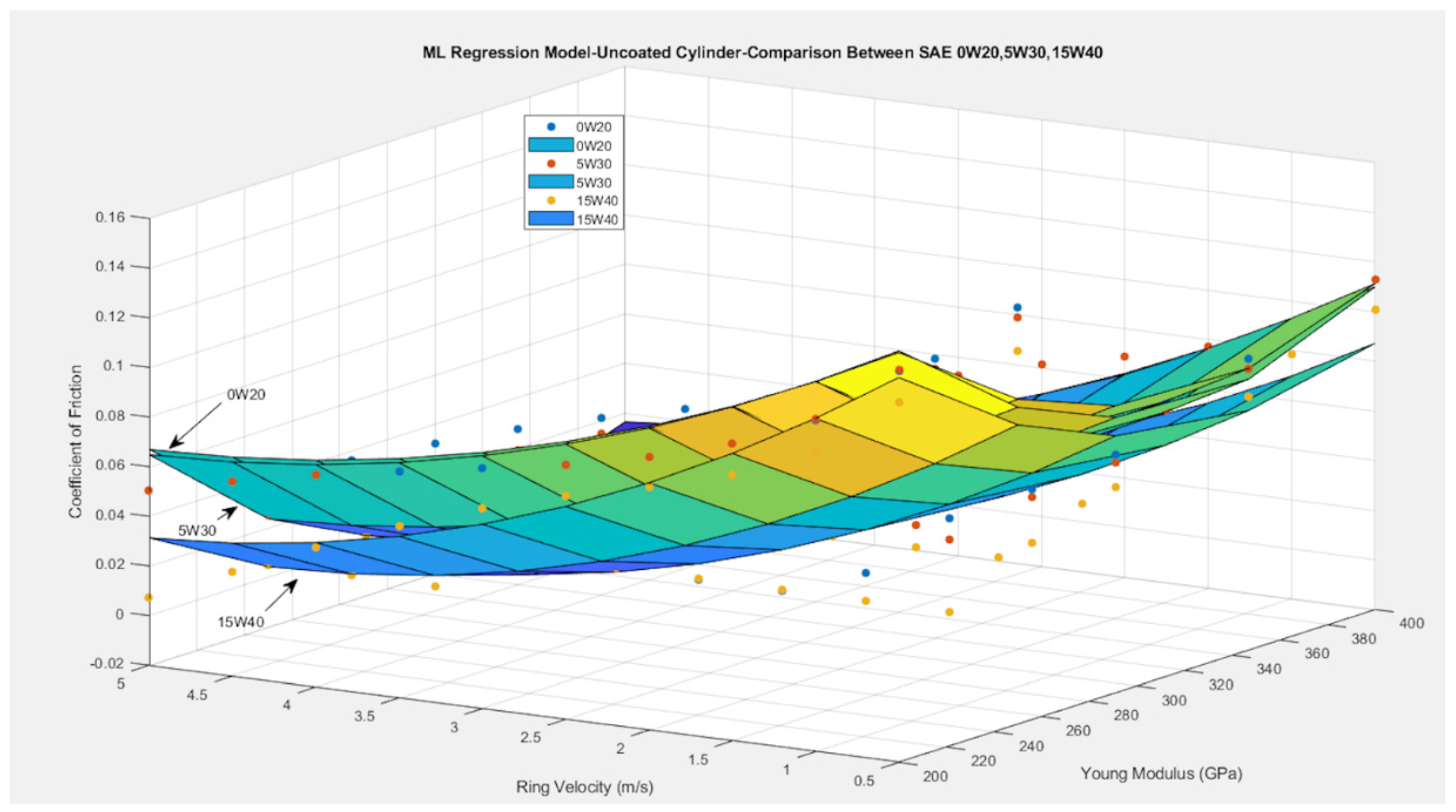
Figure 4 shows the change of the friction coefficient incorporating the multi-variable, 2nd-order polynomial regression model for all coated piston rings lubricated with SAE 0W20, 5W30 and 15W40 using an (uncoated) aluminum cylinder. The Young’s modulus shows the type of coatings in the ring surface. CrN, TiN1, TiN2 and TiAlN coatings were analyzed and compared (see Table 2). The coatings were tested under a constant load of 60 N in the range of 0.5 to 5 m/s. The data points represent the computed analytical values used as input for the model generation. The blue points correspond to the analytical values for the case of the SAE 0W20, the red points express the values for the case of the SAE 5W30 and the yellow points present the values of the SAE 15W40. As can be seen, the generated surfaces are in well conformance with the analytical predictions. In the case of SAE 15W40, the regression model is given by Equation (31) with R 2 = 0.83 and standard error of the estimate S = 0.017, which means 83% accuracy of predicting the corresponding results with an average deviation of 0.017. Similarly, in the case of SAE 5W30, the equation of the prediction model for the coefficient of friction is (32) with R 2 = 0.82 and S = 0.018, which means 82% of accuracy in prediction of the actual coefficient of friction for the contact with an average deviation of 0.018. Additionally, in the case of SAE 0W20, the regression model is given by Equation (33) with R 2 = 0.80 and S = 0.019 or 80% accurate prediction for the friction coefficient in terms of sliding velocity and young modulus of the coating with an average deviation of 0.018 from the observed values.
With regard to the tribological view, in the case of the steel piston ring, the value of the friction coefficient varies from 0.12 to 0.02 in the range of 0.5−5 m/s lubricated with SAE 15W40. Using the SAE 5W30 oil, the friction coefficient varies from 0.13 to 0.05, while for the SAE 0W20 oil, this value increased moderately, ranging from 0.14 to 0.06. In the case of CrN coating, the friction coefficient varies from 0.1 to 0.007 for SAE 15W40, while this value increased from 0.11 to 0.008 for both lubricants SAE 5W30 and SAE 0W20. A rougher TiN1 coating showed higher coefficient frictions ranging from 0.18 to 0.02 for SAE 15W40 and from 0.2 to 0.04 for both lower viscosity oils (SAE 5W30 and 0W20). At the same time, the smooth TiN2 and TiAlN coatings are characterized by lower friction coefficients. The TiN2 coating showed friction coefficients from 0.08 to 0.0045 for SAE 15W40 and from 0.095 to 0.0048 for SAE 5W30 and SAE 0W20 accordingly. Smoother TiAlN is characterized by lower friction coefficients of 0.06−0.0043 for SAE 15W40 and from 0.076 to 0.0044 for SAE 5W30 and SAE 0W20 accordingly. This explains the impact of the surface roughness through the roughness parameter (ζκσ) and asperity slope (σ/κ) in the mixed regime of lubrication. Steel had the highest surface roughness, which was followed by TiN1, CrN, TiN2 and TiAlN. The change of friction coefficient is in good agreement with the experimental work of Wróblewski et al. [17], where the morphology of the TiAlN layer shows some deep defects and slight peaks, which can enhance hydrodynamic lubrication conditions. For example, in the case of CrN, the friction coefficient varies from 0.13 to 0.11 using the same synthetic oil SAE 5W30 and sliding speed at both studies, while in the case of smoother TiAlN, the friction coefficient also changes from 0.06 to 0.076. Little variation is indicated between values. This difference means that the contribution of the piston ring profile is essential in the numerical prediction of the total friction.
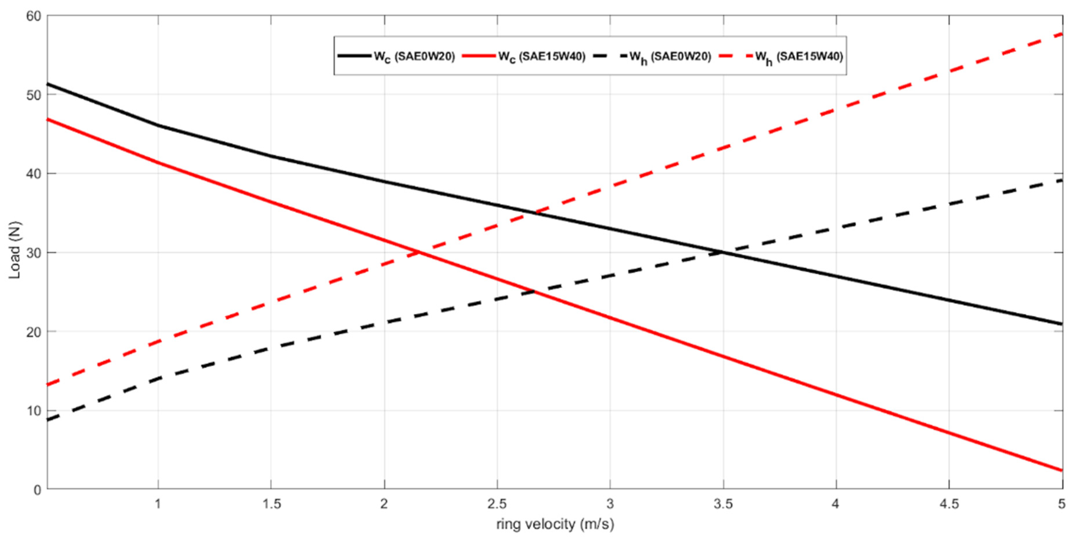
The developed model found lower coefficient values when all the coated piston rings were lubricated with SAE 15W40 owing to their higher lubricant viscosity, as the ring profile moved away from the boundary and into the mixed/hydrodynamic lubrication. This is obvious by the more rapid increase in generated hydrodynamic load for synthetic oil SAE 15W40; in addition, the fluid velocity becomes higher, and the lubricant viscosity is greater. This behavior is illustrated in Figure 5. This figure shows the comparison of the hydrodynamic load and the load carried by the asperities using the low viscosity oil SAE 0W20 and CrN layer. It is obvious the SAE 15W40 oil has lower load by the asperities compared to the oil SAE 0W20. This difference is generally 16–70%. This can be explained due to the higher lubricant viscosity of SAE 15W40 related to the oil SAE 0W20, where its dynamic viscosity is quite lower. In addition to this, the generated minimum films produced higher loads due to the asperities within the contact. For instance, the minimum film varies from 0.3 to 0.43 μm for SAE 0W20 and SAE 15W40 accordingly at a low sliding speed of 0.5 m/s.
Coated cylinder liner surfaces have also a great focus on piston ring tribology. For this reason, the effect of the Nickel Nanocomposite (NNC) coated cylinder was investigated in the current analysis. Data were provided by Dolatabadi et al. [15]. 
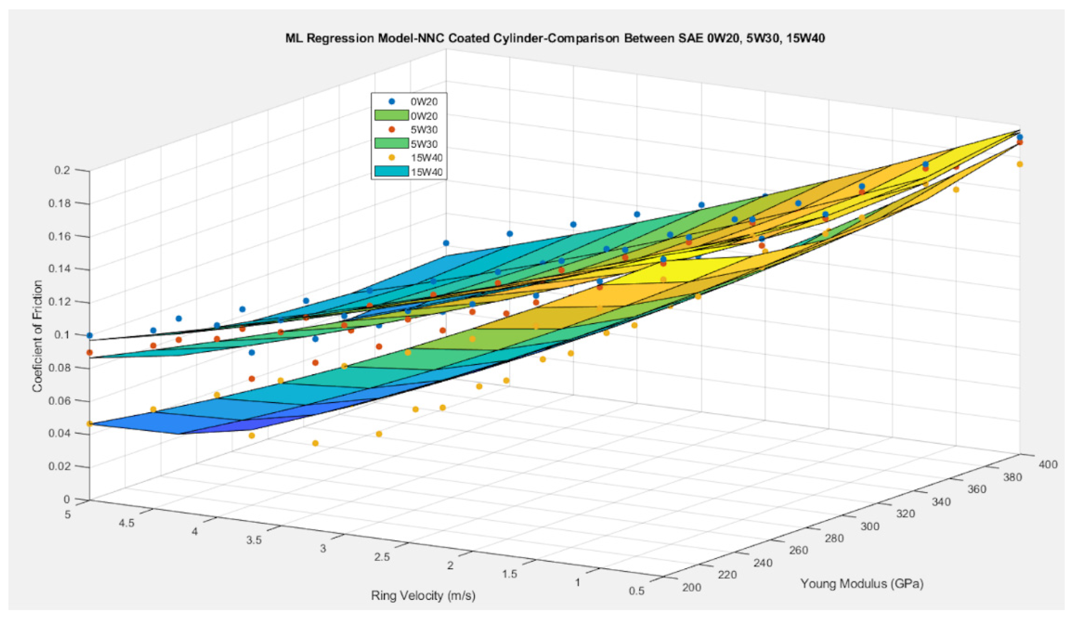
Figure 6 shows the variation of the friction coefficient using the multi-variable, 2nd-order polynomial regression model for all coated piston rings lubricated with SAE 0W20, 5W30 and 15W40. The generated surfaces are also in well conformance with the analytical predictions. In the case of SAE 15W40, the regression model is expressed by Equation (34) with R 2 = 0.97 and S = 0.010, which means 97% accuracy of predicting the corresponding results with an average standard error of 0.010. In the case of SAE 5W30, the equation of the prediction model for the coefficient of friction is defined as (35) with R 2 = 0.96 and S = 0.009, which means 96% accuracy in prediction of the actual coefficient of friction for the contact with an average standard error of 0.009. Finally, in the case of SAE 0W20, the regression model is given by Equation (36) with R 2 = 0.95 and S = 0.008 or 95% accurate prediction for the friction coefficient in terms of sliding velocity and Young’s modulus of the coating with an average standard error of 0.008. This type of cylinder liner is more rough than uncoated. Thus, the values of the friction coefficient are higher than those of the uncoated case. In more details, in the case of a rough steel ring, the friction coefficient varies from 0.12 to 0.02 for SAE 15W40 and an uncoated cylinder, while the friction coefficient changes from 0.19 to 0.047 using an NNC-coated cylinder. An increment of 33.3% is obvious. Using the NNC cylinder liner, the smoother TiAlN coatings showed better friction coefficients ranging from 0.17 to 0.005 for SAE 15W40 and from 0.18 to 0.04 but not lower using an uncoated cylinder. This can be explained owing to the cylinder surface morphology and high roughness.
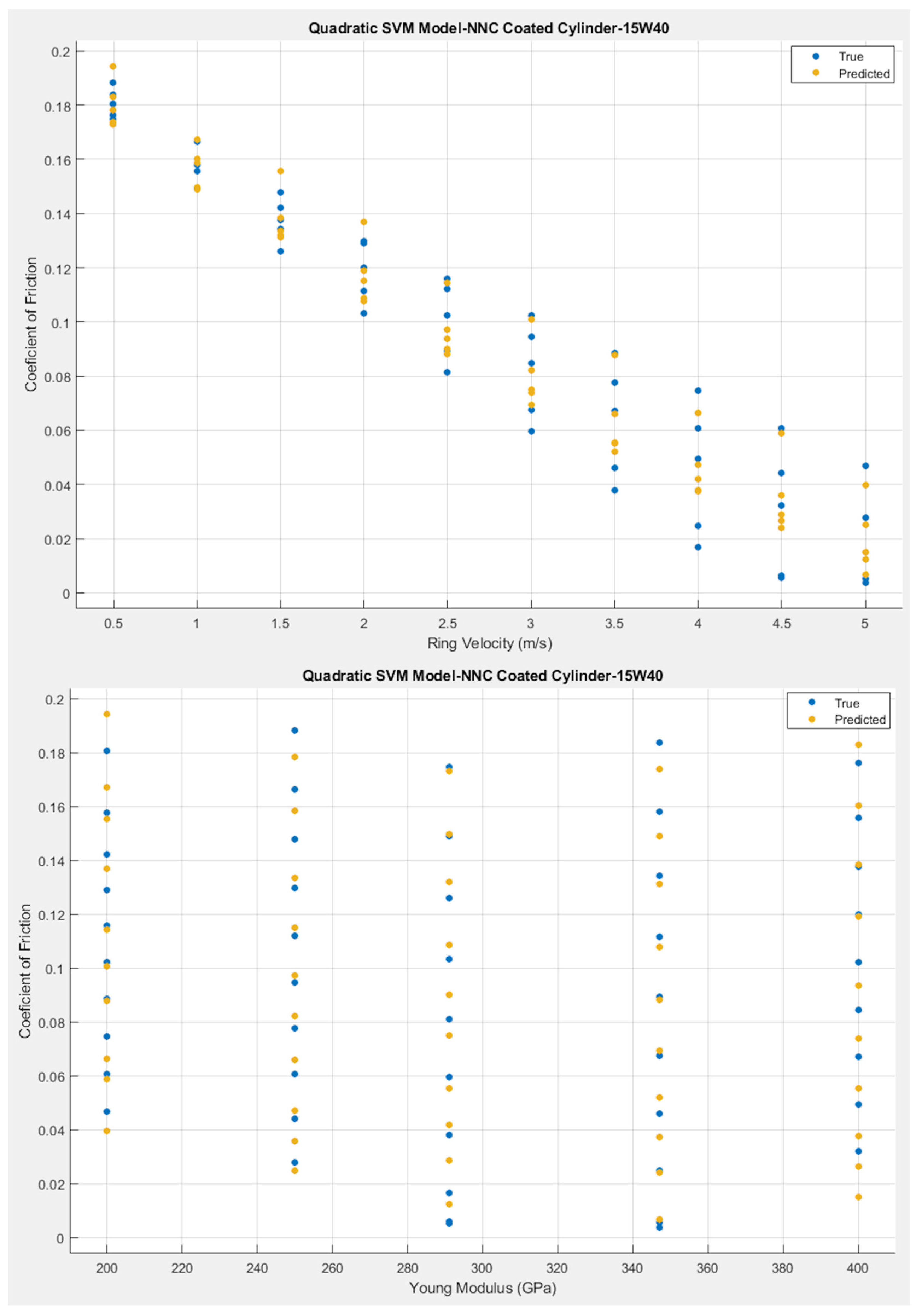
For comparison purposes, the SAE 15W40 dataset of the NNC-coated cylinder was introduced to Matlab’s Regression Learner tool. A quadratic SVM Machine Learning model was trained using 80% of the values, and a cross-validation procedure was followed for k = 5 randomly chosen partitions of the original dataset. The graphical representation of the results is shown in Figure 7. The quadratic SVM model provided a coefficient of determination R 2 = 0.96 which is lower than the R 2 = 0.97 provided by the 2nd order polynomial regression model developed by the authors. The regression model shows 1% better accuracy in predicting the friction coefficient and at the same time is easier to apply and interpret. As a result, it is suggested as the most suitable ML model for this specific investigation.
The results for the pivoted pad thrust bearing are summarized in Figure 8. The data points represent the analytical results with the blue marks referring to the results of SAE 30, red marks referring to the results of SAE 10W40 and yellow marks referring to AWS 100. Accordingly, the generated surfaces form the graphical representations of the regression models generated and compared for all the studied cases. The coefficient of friction is used in the y axis as a response value, while the first predictor appears in the x axis, sliding velocity, and the second predictor appears in the z axis, Young’s modulus, which in fact represents the various coatings examined for the current study. In the case of SAE 30, the regression model in given by Equation (37) with R 2 = 0.89 and S = 0.017; this means 89% accuracy of predicting the corresponding results with an average deviation of 0.017 units. Similarly, in the case of SAE 10W40, the equation of the prediction model for the coefficient of friction is (38) with R 2 = 0.90 and S = 0.015, which means 90% accuracy in prediction of the actual coefficient of friction for the contact with an average error of 0.015 for the estimation. Finally, in the case of AWS 100, the regression model is given by Equation (39) with R 2 = 0.85 and S = 0.021 or 85% accurate prediction for the friction coefficient in terms of sliding velocity and Young’s modulus of the coating with an average deviation from the observations of 0.021.
It can be easily noted that AWS 100 presents the highest coefficient of friction values while SAE 10W40 presents the lowest in the same operating conditions. This is explained by the fact that the sliding velocities are really low (0.5 to 5 m/s), and the load is high enough (7000 N) to keep the conjunction in mixed lubrication regime. As a result, the boundary friction has a clear effect on the final values of the friction coefficient. To add to that, AWS 100 and SAE 30 are thinner lubricants with lower viscosity values, while SAE 10W40 has the highest viscosity values in the same operating conditions. When asperities come into contact, the thicker lubricant SAE 10W40 provides better lubrication for the tribo-couple, reducing the final coefficient of friction in comparison to the thinner SAE 30 and AWS 100.
In terms of Young’s modulus, the highest values for the friction coefficient are noted at 200 GPa, which is a number that represents the steel uncoated pad, regardless of the lubricant tested. Similarly, high friction coefficient values are observed for 250 GPa, which is the Young’s modulus of TiN coating followed by the ones in 400 GPa where the CrN coating is represented. At the same time, lower friction coefficient values are observed at 291 GPa that represent the TiAlN, and the lowest values of all, regardless of the lubricant examined, are noted for a Young’s modulus equal to 300 GPa, which represents the DLC coating. This behavior is explained by the roughness of the surfaces examined. The steel uncoated pad is the roughest of all, and that is why it demonstrated the highest friction coefficient values. On the other hand, TiAlN and DLC are the coatings with the lowest surface roughness values that lead to the lowest friction coefficient values accordingly.
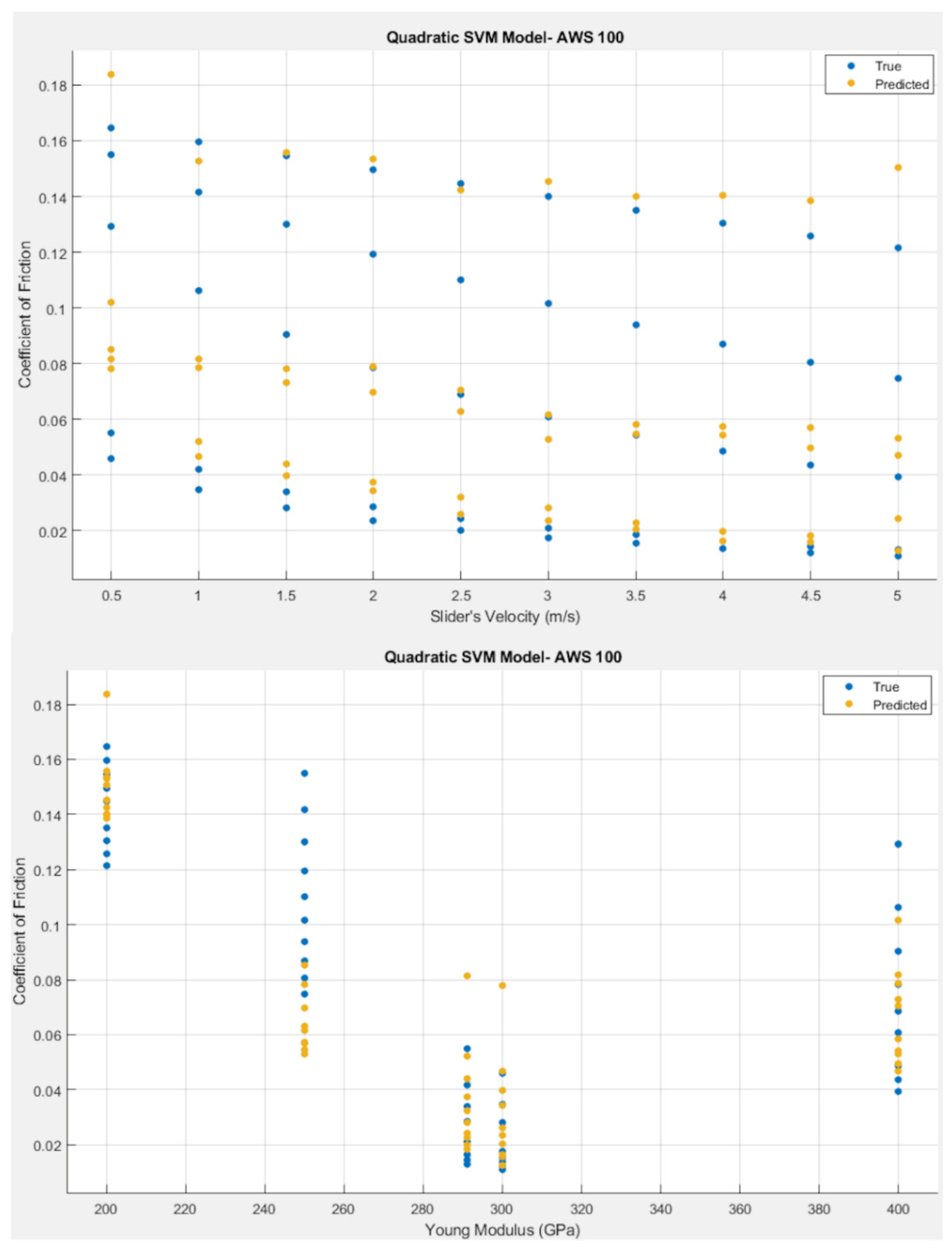
For comparison purposes, the AWS 100 dataset was introduced to Matlab’s Regression Learner tool. A quadratic SVM machine learning model was trained using 80% of the values, and a cross-validation procedure was followed for k = 5 randomly chosen partitions of the original dataset. The graphical representation of the results is shown in Figure 9. The quadratic SVM model provided a coefficient of determination R 2 = 0.79 , which is lower than R 2 = 0.85 provided by the 2nd-order polynomial regression model developed by the authors. This is a clear indication that the 2nd-order polynomial regression model has 6% better accuracy in predicting the friction coefficient values for the pivoted pad bearing in the case of AWS 100 examined and is definitely preferred to the quadratic SVM model.

5. Conclusions

The original contributions covered in the present study are summarized as follows:
  • Smooth TiN2 and TiAlN coatings proved lower friction coefficients in piston ring conjunction for both cylinder liners. The NNC cylinder liner has shown higher friction coefficients of 33.3% than the uncoated liner for all studied coated piston rings. This can be explained owing to the surface roughness properties of the contact. Practically, the ring durability can be enhanced while the frictional losses become higher. Thus, the topography of these coatings is important to improve its tribological performance. For example, surface textures can lead to better friction results as it is studied by Akbarzadeh and Khonsari [14].
  • SAE 10W40 provided better lubrication and the lowest friction coefficient values for the pivoted pad thrust bearing compared to SAE 30 and AWS 100, which are much thinner oils regardless of the coating applied. The DLC coating, having the least roughness of all, showed better tribological performance.
  • In both tribological couples, the 2nd-order polynomial regression models were found to be more accurate in predicting the friction coefficient as well as easier to apply and interpret. As a result, they are suggested to be more suitable for this investigation in comparison to the quadratic SVM models developed in Matlab’s Regression Learner tool.
The study can be further improved using experimental predictions. It would be useful to determine the wear and hardness of the coated surfaces with the inclusion of nanoparticles at high temperatures for both sliding contacts. Additionally, the effects of the flow factors that show how the roughness obstructs the flow between surfaces in proximity, and the deformations on the generated results can be investigated as well. Variations in the input data would provide improved complexity for the models. Finally, the investigation of more tribo-contacts and comparison with other Machine Learning algorithms (decision trees, neural networks) would be of great importance for the generalization of the application. These issues are the focus of ongoing research.

Author Contributions

Conceptualization, writing—review and editing, P.G.N.; writing—original draft preparation, methodology, software and machine learning, A.Z. and K.P.K.; All authors carried out interpretations for the results. All authors have read and agreed to the published version of the manuscript.

Funding

This research received no external funding.

Institutional Review Board Statement

Not applicable.

Informed Consent Statement

Not applicable.

Data Availability Statement

Not applicable.

Conflicts of Interest

The authors declare no conflict of interest.

Nomenclature

Anominal contact area
Acasperity contact area
bring face-width contact
bcrcritical length along the ring face-width contact
Bpad face width
cring curvature
dtbthrust bearing diameter
EYoung’s modulus of elasticity
E*equivalent Young’s modulus of elasticity
Fapplied load
ftottotal friction
fvviscous friction
fbboundary friction
F5/2, F2statistical functions
hlubricant film thickness
hcrcritical film thickness
hominimum film thickness
h1inlet film thickness
hsring face-width
kVogel parameter for describing lubricant viscosity variation with temperature
Kconvergence ration
Llateral length
phhydrodynamic pressure
pininlet pressure at the piston ring conjunction
poutoutlet pressure at the piston ring conjunction
rradius of the ring curvature
Raaverage roughness
Sstandard error of the estimate
M, Ninput variables
U sliding velocity
Wtottotal load carrying capacity
Wcload share by the asperities
Whload carried by the lubricant film
Greek symbols
εdamping coefficient
ζsurface density of asperity peaks
θ1, θ2Vogel parameters for lubricant viscosity variation with temperature
θav(average) lubricant temperature
κaverage asperity tip radius
λsStribeck oil film parameter ( λ s = h o σ )
μlubricant dynamic viscosity
μaspcoefficient of boundary shear strength
νPoisson ratio
σroot mean square roughness value of the studied tribo-pair
Σparameter for convergence criterion
τviscous shear stress
τοEyring shear stress of the lubricant film
Superscripts
niteration step
Subscripts
aspasperity
bboundary
crcritical
ccontact
hhydrodynamic
lliner
ppad
rring
rotrotor
sshape
SStribeck
tbthrust bearing
tottotal
vviscous
Abbreviations
AIArtificial Intelligence
AFMAtomic Force Microscope
ANNArtificial Neural Network
CFDComputational Fluid Dynamics
DLCDiamond-Like Carbon
FDMFinite Difference Method
MLMachine Learning
NEDCNew European Drive Cycle
RULRemaining Useful Life
SVRSupport Vector Regression
SVMSupport Vector Machine
TDCTop Dead Center

References

  1. Kamo, R.; Bryzik, W.; Reid, M.; Woods, M. Coatings for improving engine performance. SAE Trans. 1997, 106, 354–363. [Google Scholar]
  2. Priest, M.; Taylor, C.M. Automobile engine tribology—Approaching the surface. Wear 2000, 241, 193–203. [Google Scholar] [CrossRef]
  3. Tzanakis, I.; Hadfield, M.; Thomas, B.; Noya, S.M.; Henshaw, I.; Austen, S. Future perspectives on sustainable tribology. Renew. Sustain. Energy Rev. 2012, 16, 4126–4140. [Google Scholar] [CrossRef] [Green Version]
  4. Castleman, R.A., Jr. A hydrodynamical theory of piston ring lubrication. Physics 1936, 7, 364–367. [Google Scholar] [CrossRef]
  5. Eilon, S.; Saunders, O.A. A study of piston-ring lubrication. Proc. Inst. Mech. Eng. 1957, 171, 427–462. [Google Scholar] [CrossRef]
  6. Furuhama, S. A dynamic theory of piston-ring lubrication: 2nd report, experiment. Bull. JSME 1960, 3, 291–297. [Google Scholar] [CrossRef] [Green Version]
  7. Brown, S.R.; Hamilton, G.M. The partially lubricated piston ring. J. Mech. Eng. Sci. 1977, 19, 81–89. [Google Scholar] [CrossRef]
  8. Ma, M.T.; Sherrington, I.; Smith, E.H. Effects of Bore Out-of-Roundness on the Predicted Performance of Piston Rings in Internal Combustion Engines. Tribol. Ser. 1995, 30, 367–379. [Google Scholar]
  9. Tian, T. Dynamic behaviours of piston rings and their practical impact. Part 1: Ring flutter and ring collapse and their effects on gas flow and oil transport. Proc. Inst. Mech. Eng. Part J J. Eng. Tribol. 2002, 216, 209–228. [Google Scholar] [CrossRef]
  10. Baker, C.E.; Theodossiades, S.; Rahnejat, H.; Fitzsimons, B. Influence of in-plane dynamics of thin compression rings on friction in internal combustion engines. J. Eng. Gas Turbines Power 2012, 134, 092801. [Google Scholar] [CrossRef] [Green Version]
  11. Zavos, A.; Nikolakopoulos, P.G. Tribology of new thin compression ring of fired engine under controlled conditions—A combined experimental and numerical study. Tribol. Int. 2018, 128, 214–230. [Google Scholar] [CrossRef]
  12. Taylor, R.I.; Morgan, N.; Mainwaring, R.; Davenport, T. How much mixed/boundary friction is there in an engine—And where is it? Proc. Inst. Mech. Eng. Part J J. Eng. Tribol. 2020, 234, 1563–1579. [Google Scholar] [CrossRef]
  13. Knauder, C.; Allmaier, H.; Sander, D.E.; Sams, T. Investigations of the friction losses of different engine concepts: Part 3: Friction reduction potentials and risk assessment at the sub-assembly level. Lubricants 2020, 8, 39. [Google Scholar] [CrossRef] [Green Version]
  14. Akbarzadeh, A.; Khonsari, M.M. Effect of untampered plasma coating and surface texturing on friction and running-in behavior of piston rings. Coatings 2018, 8, 110. [Google Scholar] [CrossRef] [Green Version]
  15. Dolatabadi, N.; Forder, M.; Morris, N.; Rahmani, R.; Rahnejat, H.; Howell-Smith, S. Influence of advanced cylinder coatings on vehicular fuel economy and emissions in piston compression ring conjunction. Appl. Energy 2020, 259, 114129. [Google Scholar] [CrossRef]
  16. Gore, M.; Morris, N.; Rahmani, R.; Rahnejat, H.; King, P.D.; Howell-Smith, S. A combined analytical-experimental investigation of friction in cylinder liner inserts under mixed and boundary regimes of lubrication. Lubr. Sci. 2017, 29, 293–316. [Google Scholar] [CrossRef] [Green Version]
  17. Wróblewski, P.; Rogólski, R. Experimental Analysis of the Influence of the Application of TiN, TiAlN, CrN and DLC1 Coatings on the Friction Losses in an Aviation Internal Combustion Engine Intended for the Propulsion of Ultralight Aircraft. Materials 2021, 14, 6839. [Google Scholar] [CrossRef]
  18. Zavos, A. Effect of Coating and Low Viscosity Oils on Piston Ring Friction under Mixed Regime of Lubrication through Analytical Modelling. Lubricants 2021, 9, 124. [Google Scholar] [CrossRef]
  19. Li, S.; Zhang, R.; Jin, Y.; Wang, Y.; Tung, S.C. Competitive surface interactions of critical additives with piston ring/cylinder liner components under lubricated breaking-in conditions. Tribol. Trans. 2003, 46, 200–205. [Google Scholar] [CrossRef]
  20. Zhmud, B.; Tomanik, E.; Grabon, W.; Schorr, D.; Brodmann, B. Optimizing the Piston/Bore Tribology: The Role of Surface Specifications, Ring Pack, and Lubricant; Society of Automotive Engineers: Warrendale, PA, USA, 2020; Technical Paper No. 2020-01-2167. [Google Scholar]
  21. Shahmohamadi, H.; Rahmani, R.; Rahnejat, H.; Garner, C.P.; Balodimos, N. Thermohydrodynamics of lubricant flow with carbon nanoparticles in tribological contacts. Tribol. Int. 2017, 113, 50–57. [Google Scholar] [CrossRef] [Green Version]
  22. Zavos, A.; Nikolakopoulos, P.G. Modelling of transient flow of piston ring-liner contact using synthetic lubricants. Proc. Inst. Mech. Eng. Part J J. Eng. Tribol. 2021. [Google Scholar] [CrossRef]
  23. Anandan, N.; Sathiamurugan, P.; Mathiazhagan, P. Load Carrying Capacity of Adiabatically Lubricated Thrust Bearings with Various Film Profiles. Univers. J. Mech. Eng. 2014, 2, 94–100. [Google Scholar] [CrossRef] [Green Version]
  24. Papadopoulos, C.I.; Nikolakopoulos, P.G.; Kaiktsis, L. Evolutionary optimization of micro-thrust bearings with periodic partial trapezoidal surface texturing. J. Eng. Gas Turbines Power 2010, 133, 012301. [Google Scholar] [CrossRef]
  25. Mahieux, C.A. Experimental Characterization of the Influence of Coating Materials on the Hydrodynamic Behavior of Thrust Bearings: A Comparison of Babbitt, PTFE, and PFA. Trans. ASME 2005, 127, 568–574. [Google Scholar] [CrossRef]
  26. Jahanmir, S.; Hunsberger, A.Z.; Heshmat, H. Load Capacity and Durability of H-DLC Coated Hydrodynamic Thrust Bearings. J. Tribol. 2011, 133, 031301. [Google Scholar] [CrossRef]
  27. Katsaros, K.; Bompos, D.A.; Nikolakopoulos, P.G.; Theodossiades, S. Thermal–Hydrodynamic Behaviour of Coated Pivoted Pad Thrust Bearings: Comparison between Babbitt, PTFE and DLC. Lubricants 2018, 6, 50. [Google Scholar] [CrossRef] [Green Version]
  28. Nunez, E.E.; Gheisari, R.; Polycarpou, A.A. Tribology review of blended bulk polymers and their coatings for high-load bearing applications. Tribol. Int. 2019, 129, 92–111. [Google Scholar] [CrossRef]
  29. Rosenkranz, A.; Marian, M.; Profito, F.J.; Aragon, N.; Shah, R. The use of artificial intelligence in tribology—A perspective. Lubricants 2021, 9, 2. [Google Scholar] [CrossRef]
  30. Moon, I.Y.; Jeong, H.W.; Lee, H.W.; Kim, S.J.; Oh, Y.S.; Jung, J.; Oh, S.; Kang, S.H. Predicting High Temperature Flow Stress of Nickel Alloy A230 Based on an Artificial Neural Network. Metals 2022, 12, 223. [Google Scholar] [CrossRef]
  31. Bhaumik, S.; Pathak, S.D.; Dey, S.; Datta, S. Artificial intelligence based design of multiple friction modifiers dispersed castor oil and evaluating its tribological properties. Tribol. Int. 2019, 140, 105813. [Google Scholar] [CrossRef]
  32. Saridakis, K.M.; Nikolakopoulos, P.G.; Papadopoulos, C.A.; Dentsoras, A.J. Identification of wear and misalignment on journal bearings using artificial neural networks. Proc. Inst. Mech. Eng. Part J J. Eng. Tribol. 2012, 226, 46–56. [Google Scholar] [CrossRef]
  33. Kokkinidis, K.A.; Nikolakopoulos, P.G. Simulation of misaligned journal bearing using Neural Network. Tribol. Ind. 2022, 44, 183–197. [Google Scholar] [CrossRef]
  34. Ahmad, W.; Khan, S.A.; Islam, M.M.; Kim, J.M. A reliable technique for remaining useful life estimation of rolling element bearings using dynamic regression models. Reliab. Eng. Syst. Saf. 2019, 184, 67–76. [Google Scholar] [CrossRef]
  35. Katsaros, K.P.; Nikolakopoulos, P.G. On the tilting-pad thrust bearings hydrodynamic lubrication under combined numerical and machine learning techniques. Lubr. Sci. 2021, 33, 153–170. [Google Scholar] [CrossRef]
  36. Rossopoulos, G.N.; Papadopoulos, C.I. A journal bearing performance prediction method utilizing a machine learning technique. Proc. Inst. Mech. Eng. Part J J. Eng. Tribol. 2021. [Google Scholar] [CrossRef]
  37. Senatore, A.; Ciortan, S. An application of artificial neural networks to piston ring friction losses prediction. Mech. Test. Diagn. 2011, 1, 7–14. [Google Scholar]
  38. Wołowiec-Korecka, E.; Kula, P.; Pawęta, S.; Pietrasik, R.; Sawicki, J.; Rzepkowski, A. Neural computing for a low-frictional coatings manufacturing of aircraft engines’ piston rings. Neural Comput. Appl. 2019, 31, 4891–4901. [Google Scholar] [CrossRef] [Green Version]
  39. Katsaros, K.P.; Nikolakopoulos, P.G. Optimal Designs of Tilting-Pad Thrust Bearing Operation with the Combination of Numerical and Machine Learning Techniques. In Proceedings of the 6th International Conference of Engineering Against Failure (ICEAF-VI 2021), Spetses, Greece, 23–25 June 2021; Volume 349, p. 03003. [Google Scholar]
  40. Greenwood, J.A.; Tripp, J.H. The contact of two nominally flat rough surfaces. Proc. Inst. Mech. Eng. 1970, 185, 625–633. [Google Scholar] [CrossRef]
  41. Mishra, P.C.; Balakrishnan, S.; Rahnejat, H. Tribology of compression ring-to cylinder contact at reversal. Proc. Inst. Mech. Eng. Part J J. Eng. Tribol. 2008, 222, 815–826. [Google Scholar] [CrossRef] [Green Version]
  42. Gohar, R.; Rahnejat, H. Fundamentals of Tribology; Imperial College Press: London, UK, 2008; ISBN 978-1-84816860-2. [Google Scholar]
  43. Teodorescu, M.; Balakrishnan, S.; Rahnejat, H. Integrated tribological analysis within a multi-physics approach to system dynamics. Tribol. Interface Eng. Ser. 2005, 48, 725–737. [Google Scholar]
  44. Umer, J.; Morris, N.; Leighton, M.; Rahmani, R.; Howell-Smith, S.; Wild, R.; Rahnejat, H. Asperity level tribological investigation of automotive bore material and coatings. Tribol. Int. 2018, 117, 131–140. [Google Scholar] [CrossRef] [Green Version]
  45. Aurelian, F.; Patrick, M.; Mohamed, H. Wall slip effects in (elasto) hydrodynamic journal bearings. Tribol Int. 2011, 44, 868–877. [Google Scholar] [CrossRef]
  46. Stachowiak, G.W.; Batchelor, A.W. Engineering Tribology, 2nd ed.; Elsevier: Amsterdam, The Netherlands, 2001. [Google Scholar]
  47. Vogel, H. The law of the relation between the viscosity of liquids and the temperature. Phys. Z. 1921, 22, 645–646. [Google Scholar]
  48. Rahmani, R.; Rahnejat, H.; Fitzsimons, B.; Dowson, D. The effect of cylinder liner operating temperature on frictional loss and engine emissions in piston ring conjunction. Appl. Energy 2017, 191, 568–581. [Google Scholar] [CrossRef] [Green Version]
  49. Maulud, D.; Abdulazeez, A.M. A Review on Linear Regression Comprehensive in Machine Learning. J. Appl. Sci. Technol. Trends 2020, 1, 140–147. [Google Scholar] [CrossRef]
  50. Elasha, F.; Shanbr, S.; Li, X.; Mba, D. Prognosis of a Wind Turbine Gearbox Bearing Using Supervised Machine Learning. Sensors 2019, 19, 3092. [Google Scholar] [CrossRef] [Green Version]
  51. Moder, J.; Bergmann, P.; Grün, F. Lubrication Regime Classification of Hydrodynamic Journal Bearings by Machine Learning Using Torque Data. Lubricants 2018, 6, 108. [Google Scholar] [CrossRef] [Green Version]
  52. Bielec, M.K.; Leopard, A.J. Paper 13: Tilting Pad Thrust Bearings: Factors Affecting Performance and Improvements with Directed Lubrication. Proc. Inst. Mech. Eng. Conf. Proc. 1969, 184, 93–102. [Google Scholar] [CrossRef] [Green Version]
  53. Arcoumanis, C.; Ostovar, P.; Mortimer, R. Mixed Lubrication Modeling of Newtonian and Shear Thinning Liquids in a Piston-Ring Configuration; Society of Automotive Engineers: Warrendale, PA, USA, 1997; paper No. 972924. [Google Scholar]
Figure 1. Contact parameters and flow conditions in piston ring–liner conjunction.
Coatings 12 00704 g001
Figure 2. (a): Thrust bearing assembly [27]; (b): Schematic of the pivoted pad [46]. Reprinted with permission from Ref. [46]. Copyright 2001, Elsevier; (c): Schematic of the rough surfaces.
Coatings 12 00704 g002
Figure 3. Flowchart of the analytical solution of the contacts.
Coatings 12 00704 g003
Figure 4. Multi-variable 2nd-order polynomial regression model comparison between SAE 0W20, SAE 5W30, and SAE 15W40 for coated piston rings with uncoated cylinder liner.
Coatings 12 00704 g004
Figure 5. Comparison of hydrodynamic load and asperities load between SAE 0W20 and SAE 15W40 for CrN-coated rings with an uncoated cylinder liner.
Coatings 12 00704 g005
Figure 6. Multi-variable 2nd-order polynomial regression model comparison between SAE 0W20, SAE 5W30, and SAE 15W40 for coated piston rings with an NNC cylinder liner.
Coatings 12 00704 g006
Figure 7. Quadratic SVM regression model of SAE 15W40 for an NNC cylinder liner.
Coatings 12 00704 g007
Figure 8. Multi-variable 2nd-order polynomial regression model comparison between SAE 30, SAE 10W40, and AWS 100.
Coatings 12 00704 g008
Figure 9. Quadratic SVM model results for the case of AWS 100.
Coatings 12 00704 g009
Table 1. Input parameters of the Vogel equation and the dynamic viscosities at temperature of 120 °C.
SAE 15W40SAE 5W30SAE 0W20SAE 30SAE 10W40AWS 100
k (mPa·s)0.0290.070.0710.020.0260.049
θ1 (°C)1424.3992.1983.213611420960.2
θ2 (°C)137.2111.9116.2125.1135.3110.8
μ (Pa·s)0.00730.0050.00450.00510.00670.0031
Table 2. Piston ring base dimensions and operating conditions.
ParameterValueUnit
Ring face width0.5mm
Ring radius of curvature40.5mm
Ring lateral length40mm
Applied load60N
Sliding velocity0.5−5m/s
Coefficient of boundary shear strength0.22-
Eyring shear stress2MPa
Lubricant temperature120°C
Table 3. Pivoted pad thrust bearing dimensions and operating conditions.
ParameterValueUnit
Pad face width28mm
Thrust bearing diameter124mm
Inclination0.1-
Applied load7000N
Sliding velocity0.5–5m/s
Coefficient of boundary shear strength0.22-
Eyring shear stress2MPa
Lubricant temperature120°C
Table 4. Coating properties and surface topographical parameters for piston rings.
ParameterPiston Ring Base MaterialRing CoatingsUnit
MaterialSteelCrNTiN1TiN2TiAlN-
Young’s modulus of elasticity200400250347.45291.23GPa
Poisson’s ratio0.310.20.250.250.22-
Surface roughness0.40.250.310.110.059μm
Roughness parameter (ζκσ)0.00170.00230.000480.000490.00044-
Asperity slope (σ/κ)0.00510.00340.0230.02450.023-
Table 5. Coating properties and surface topographical parameters for cylinder liners.
ParameterCylinder Liner Base MaterialCylinder Liner CoatingsUnit
MaterialAluminumNNC-
Young’s modulus
of elasticity
70165GPa
Poisson’s ratio0.330.31-
Surface roughness0.10.35μm
Table 6. Coating properties and surface topographical parameters for the pivoted pad thrust bearings.
ParameterPivoted Pad
Base Material
Pad CoatingsUnit
MaterialSteelCrNTiNTiAlNDLC-
Young’s modulus of elasticity200400250291.43300GPa
Poisson’s ratio0.310.20.250.220.25-
Surface roughness0.40.250.310.0590.033μm
Roughness parameter (ζκσ)0.0740.0150.0270.00120.0011-
Asperity slope (σ/κ)0.02230.00930.01290.00170.0015-
Table 7. Summary of the regression models.
Regression ModelsEquationsNo.
Uncoated Cylinder SAE 15W40 y = 0.449 0.055 x 0.002 z + 0.464 × 10 2 x 2 + 0.331 × 10 4 x z + 0.300 × 10 5 z 2 (31)
Uncoated Cylinder SAE 5W30 y = 0.509 0.036 x 0.0025 z + 0.380 × 10 2 x 2 0.138 × 10 4 x z + 0.388 × 10 5 z 2 (32)
Uncoated Cylinder SAE 0W20 y = 0.469 0.033 x 0.0022 z + 0.371 × 10 2 x 2 0.213 × 10 4 x z + 0.343 × 10 5 z 2 (33)
NNC Coated Cylinder SAE 15W40 y = 0.371 0.034 x 0.0011 z + 0.182 × 10 2 x 2 0.395 × 10 4 x z + 0.200 × 10 5 z 2 (34)
NNC Coated Cylinder SAE 5W30 y = 0.319 0.024 x 0.00083 z + 0.108 × 10 2 x 2 0.300 × 10 4 x z + 0.140 × 10 5 z 2 (35)
NNC Coated Cylinder SAE 0W20 y = 0.302 0.023 x 0.00069 z + 0.117 × 10 2 x 2 0.260 × 10 4 x z + 0.117 × 10 5 z 2 (36)
Pad Bearing SAE 30 y = 0.819 0.027 x 0.005 z + 0.255 × 10 2 x 2 0.139 × 10 5 x z + 0.684 × 10 5 z 2 (37)
Pad Bearing SAE 10W40 y = 0.770 0.036 x 0.004 z + 0.289 × 10 2 x 2 + 0.200 × 10 4 x z + 0.621 × 10 5 z 2 (38)
Pad Bearing AWS 100 y = 0.874 0.015 x 0.005 z + 0.200 × 10 2 x 2 0.304 × 10 4 x z + 0.766 × 10 5 z 2 (39)
Table 8. Coefficients of determination (R2) and the standard error of the estimate (S) for all the regression models.
Regression ModelsR-SquareStandard Error of the Estimate
Uncoated Cylinder SAE 15W400.830.017
Uncoated Cylinder SAE 5W300.820.018
Uncoated Cylinder SAE 0W200.800.019
NNC Coated Cylinder SAE 15W400.970.010
NNC Coated Cylinder SAE 5W300.960.009
NNC Coated Cylinder SAE 0W200.950.008
Pad Bearing SAE 300.890.017
Pad Bearing SAE 10W400.900.015
Pad Bearing AWS 1000.850.021
Publisher’s Note: MDPI stays neutral with regard to jurisdictional claims in published maps and institutional affiliations.

