1. Introduction
Clay cores have been widely used as sealing elements in embankment and rockfill dams, but some issues such as supplementing impermeable materials for the core, precise control requirements, high sensitivity to weather conditions and occurrence of phenomena such as hydraulic fracture make the use of asphaltic concrete as an impermeable material in the dam’s body more suitable [
1,
2]. Some of the most important features of asphaltic concrete materials are the self-healing properties of bitumen, simpler construction in cold and rainy conditions than clay cores, suitable flexibility and satisfactory joining with the embankment materials [
3,
4,
5]. The properties of asphaltic concrete materials mean that rockfill dams with asphaltic concrete cores are considered safer and more economic than older methods [
6].
Up until now, some numerical analyses have been carried out to evaluate the static and dynamic behavior of rockfill dams with asphaltic concrete cores. The Storvatn dam has been studied by Valstad et al. (1991) as a case study in Norway. This dam is located in a region with moderate seismicity. The authors calculated the permanent deformation of the dam by using the Newmark method. The results show that the dam’s behavior is good against earthquakes [
7]. The Kopra dam has been studied for both OBE and MCE earthquake levels by Gurdil (1999). These analyses used linear equivalent and finite element methods. Hyperbolic models were used to calculate the stresses. The results of this study imply that cracks can be created in the core of the dam. However, because of the self-healing ability of bitumen, seepage is stopped in a short period of time [
8]. Menitjes and Jones (1999) analyzed the Ceres dam in South Africa with quasi-static and dynamic methods. In the quasi-static method, 0.1 and 0.2 coefficients are considered for the Operating Base Earthquake (OBE) and Maximum Credible Earthquake (MCE). Flush software was used for dynamic analysis. Both quasi-static and dynamic results show that a dam with a 1 to 1.6 upstream slope and a 1 to 1.5 downstream slope and 7 m crest width satisfied all the safety standards [
9]. Ghanooni and Mahinroosta (2002) studied the dynamic aspects of a 115 m high rockfill. The results show that there is a large variety of settlement behavior between the core and transition zone materials. Moreover, significant cracks in the core were found [
10]. The effects of geometry on the dynamic analyses of an embankment dam with an asphaltic concrete core were studied by Gatmiri and Mokaram (2003). They concluded that geometric parameters for dams should be selected based on a dam’s seismic behavior [
11]. Numerical analyses and experimental tests were conducted by Baziar et al. (2006) to investigate the safety of a rockfill dam. Their studies show that a rockfill dam performs satisfactorily against large earthquakes or even several earthquakes [
12]. Feizi et al. (2008) studied the seismic behavior of asphaltic concrete in embankment dams under earthquake loading. Numerous monotonic and cyclic tests were applied to asphaltic concrete samples used in hydraulic structures for evaluating dynamic behavior. Temperature effects, frequency effects and fatigue were investigated on samples in isotropic and anisotropic states and geotechnical parameters were obtained for use in numerical analyses [
13]. The behavior of the Garmrood dam was evaluated with element tests, numerical analyses and shaking table tests by Feizi et al. (2009). Element test results showed that asphaltic concrete material is durable and cracks could occur only in strong earthquakes. Numerical and experimental results emphasize that the Garmrood dam has a good performance against earthquakes [
14]. Ghahreman Nejad et al. (2010) examined the seismic deformation of the Shur River dam with a bituminous concrete core as a case study. They evaluated the maximum crest settlement of the dam under three earthquake loadings using simplified procedures and numerical analyses. The results showed that failure of the asphaltic core is unlikely to occur [
15]. Akhtarpour and Khodaii (2013) investigated the behavior of asphaltic concrete used as an impervious core in a rockfill dam. They conducted an extensive series of monotonic and cyclic triaxial tests to evaluate a specimen’s dynamic behavior. The results show that the dynamic shear strains are less than 0.4% for all tests and no cracks occurred on specimen surfaces [
16]. Akhtarpour and Khodaii (2015) examined the behavior of the largest dam with an asphaltic concrete core in Iran (Shur river dam) using numerical analyses and shaking table tests. First, they obtained the parameters with triaxial tests. Then, they performed 2D and 3D non-linear analysis of the dam under seismic loads. The results showed that an applied earthquake causes cracks and increases the permeability of asphalt in the upper part of the core [
17]. Liu et al. (2015) examined the failure mechanism in rockfill dams by conducting large-scale shaking table tests. The results of the shaking table tests were consistent with the numerical results [
18]. Taylan et al. (2017) analyzed the behavior of the Drideresi-II dam under different earthquake loads. The finite element method and Ansys software were used to reflect the dam’s behavior more realistically [
19].
Moreover, some researchers have recently used FEM for identifying the static and dynamic behavior of an asphaltic concrete rockfill dam [
20,
21]. Wu et al. (2018) found that the stress distribution and deformation of the asphaltic core are appropriate during the completion and operating stages and do not cause shear failure in the asphaltic core or hydraulic failure. Moreover, after applying the seismic load, no noticeable whipping effect occurs in the dam crest. The distribution of the maximum dynamic displacement of the dam is similar to the maximum acceleration response [
22]. Feng et al. (2020) investigated the design methods and operation of the 174 m high Quxue asphaltic rockfill dam. Monitoring the dam’s performance showed that a rockfill dam with an asphaltic concrete core is safe in narrow valleys with sloping supports. The core is flexible and no cracks occurred, and internal erosion did not cause a problem [
23]. Durmaz et al. (2020) explored the development of a preliminary design method by considering the permanent displacement caused by earthquakes and the acceleration response for rockfill dams. For this purpose, numerical models with geometric properties and different materials were prepared and dynamic analysis performed with software based on the finite element method. Then, Newmark’s sliding block approach was used to calculate the permanent displacements of the acceleration records [
24]. Qiu et al. (2021) studied the behavior of the Quxue dam in China, the tallest dam with an asphaltic concrete core that has been studied as a case study. Three-dimensional nonlinear FE analysis was performed for the dam, and the results were compared with the results calculated by the two-dimensional analysis. Finally, the calculated results were compared with the monitoring data from the dam construction and the first impounding. The results showed that the concerns expressed about the safety and behavior of the asphaltic core are not correct and this type of core is safe [
25].
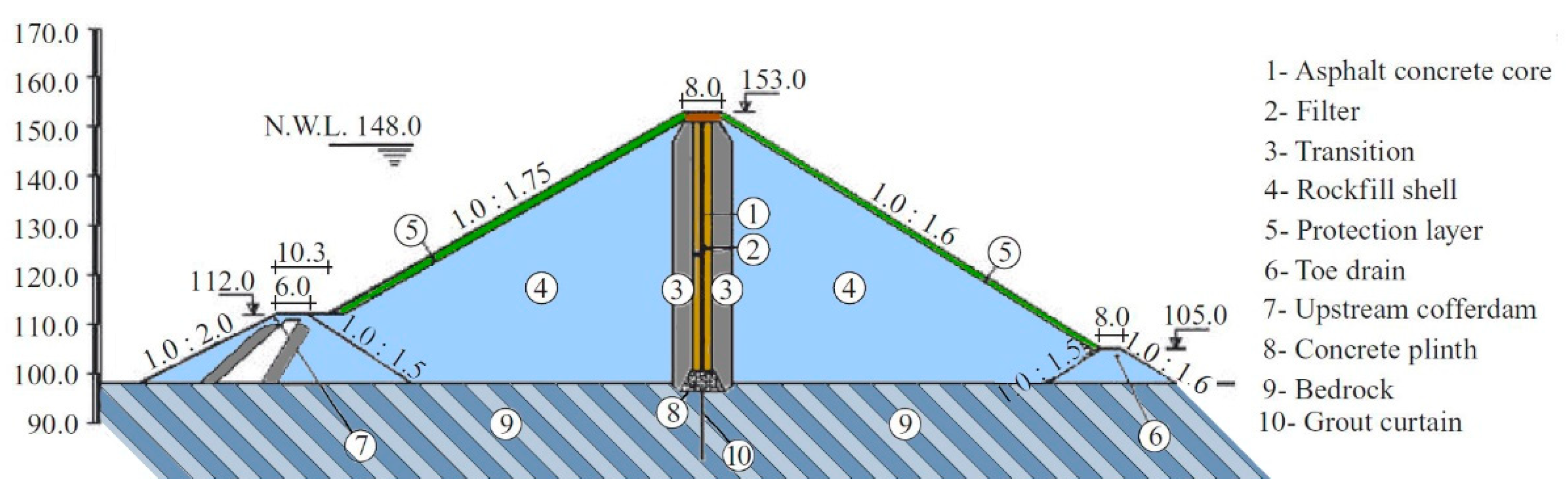
Based on the previous studies, it is observed that the static and dynamic behaviors of rockfill dams with asphaltic concrete cores have been studied satisfactory, and it is concluded that asphaltic cores in this type of dam have a good performance in static states, but in the occurrence of an earthquake, the situation will be different and further analysis should be conducted. Since Iran is located in a seismic-prone area, more studies about the behavior of these dams with different angled cores under seismic loads are required. Moreover, the International Commission on Large Dams (ICOLD) recommends that the asphaltic core be angled to reduce the risk of the upstream shell separating from the core, an issue that has rarely been investigated in previous research on rockfill dams. In this study, the Meijaran dam has been selected as a case study of rockfill dams with asphaltic concrete cores in Iran, and by considering three different core angles (90°, 60° and 45°), the effect of changing the angle on static and dynamic behavior was investigated. To this end, the dam model was generated in FLAC 2D software with three angles and the Mohr–Coulomb constitutive model was chosen to simulate the behavior of the dam body. Then, the static and dynamic behaviors of the dam for different angles were investigated, and the results are presented. Finally, numerical modeling was compared with the results of the centrifuge test to confirm the accuracy of the analysis.
3. Numerical Analyses
In this paper, 2D static and dynamic analyses based on plane strain conditions were performed using FLAC 2D software (version 8), which is an acceptable assumption considering the ratio of the length of the crest to its height. This software performs engineering calculations based on finite difference equations and correctly simulates the elastic and plastic behavior of geotechnical structures [
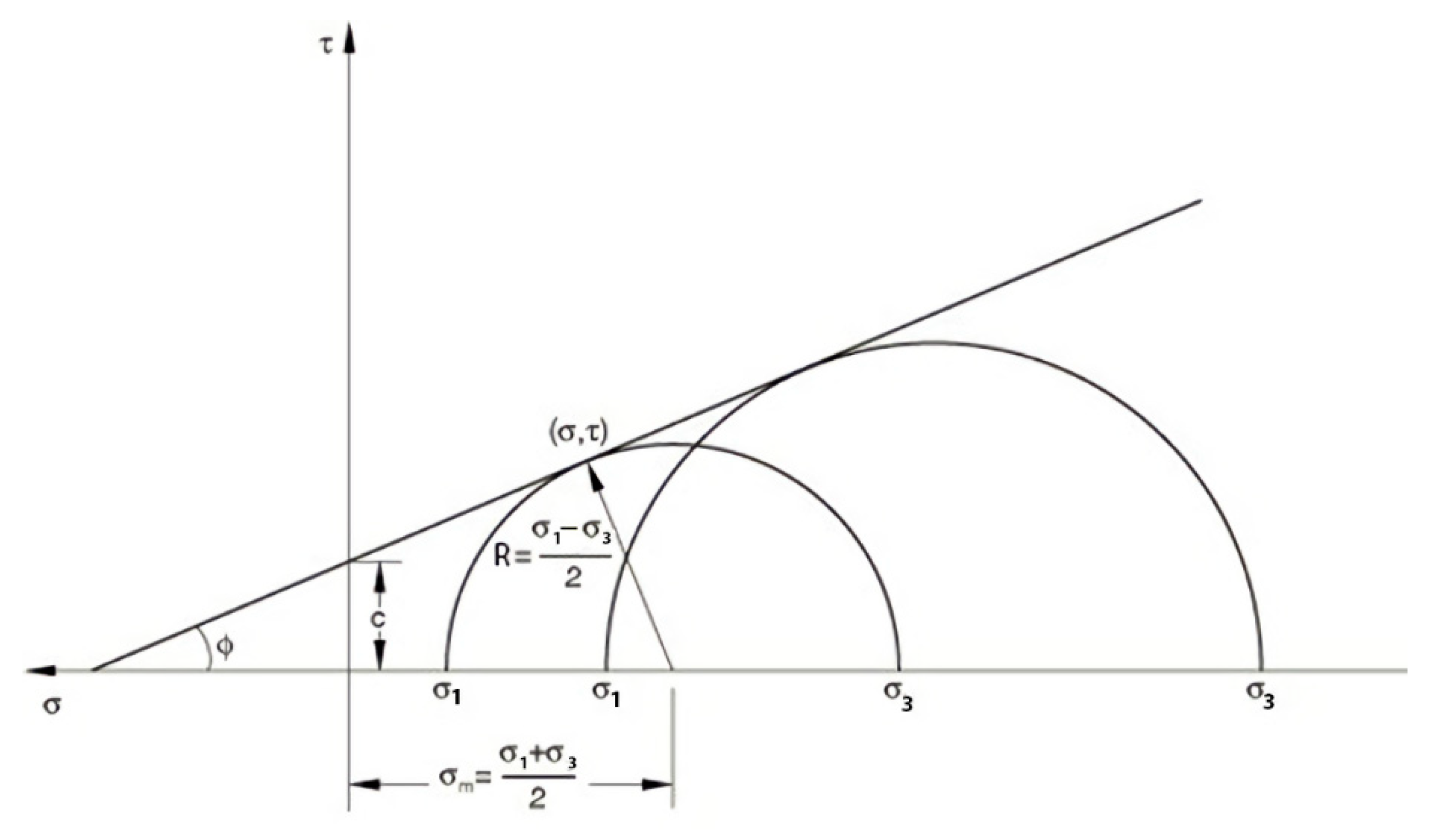
27]. The University of West Bohemia prepared a sub-cluster to cover all requested outputs. There are different constitutive models in the FLAC software. Static and dynamic analyses use the Mohr–Coulomb constitutive model, which assumes a confining pressure for body materials, filters, transition zones and foundation. This constitutive model is one of the most widely used elastoplastic constitutive models and that is primarily used in geotechnical engineering. The failure criteria for the Mohr–Coulomb constitutive model is defined in Equation (1):
where τ is the shear strength of the soil,
σn is vertical stress,
c is soil cohesion and
φ is the internal friction angle.
Figure 3 displays the Mohr–Coulomb failure surface in a linear envelope in the Mohr diagram [
28].
When the FLAC software uses the Mohr–Coulomb constitutive model, the principal stresses are used. The principal planes and principal stresses are obtained from the total stress state of the plane. An important point is the use of its three-dimensional tensor in the constitutive models in the analysis. Therefore, in cases where it is necessary to introduce initial stresses (such as in situ stresses), the third component of the main stresses must be included. However, the analyses are based on plane strain conditions.
3.1. Static Analyses
The static analyses were performed in impounding stages. As indicated above, the Mohr–Coulomb constitutive model is used in modeling. To obtain the Mohr–Coulomb parameters using the results of triaxial tests, at least two tests with different confining pressures must be performed. An effective stress solution (simultaneous solution of flow and equilibrium equations) has been used in all stages of dam construction and impounding. For this reason, all the required parameters are the parameters of the drained state. The geotechnical parameters required in the numerical analyses are listed in
Table 1 [
12]. In
Table 1,
is specific gravity,
is elastic modulus,
is internal friction angle,
is dilation angle,
is soil cohesion,
is Poisson’s ratio and
is soil permeability.
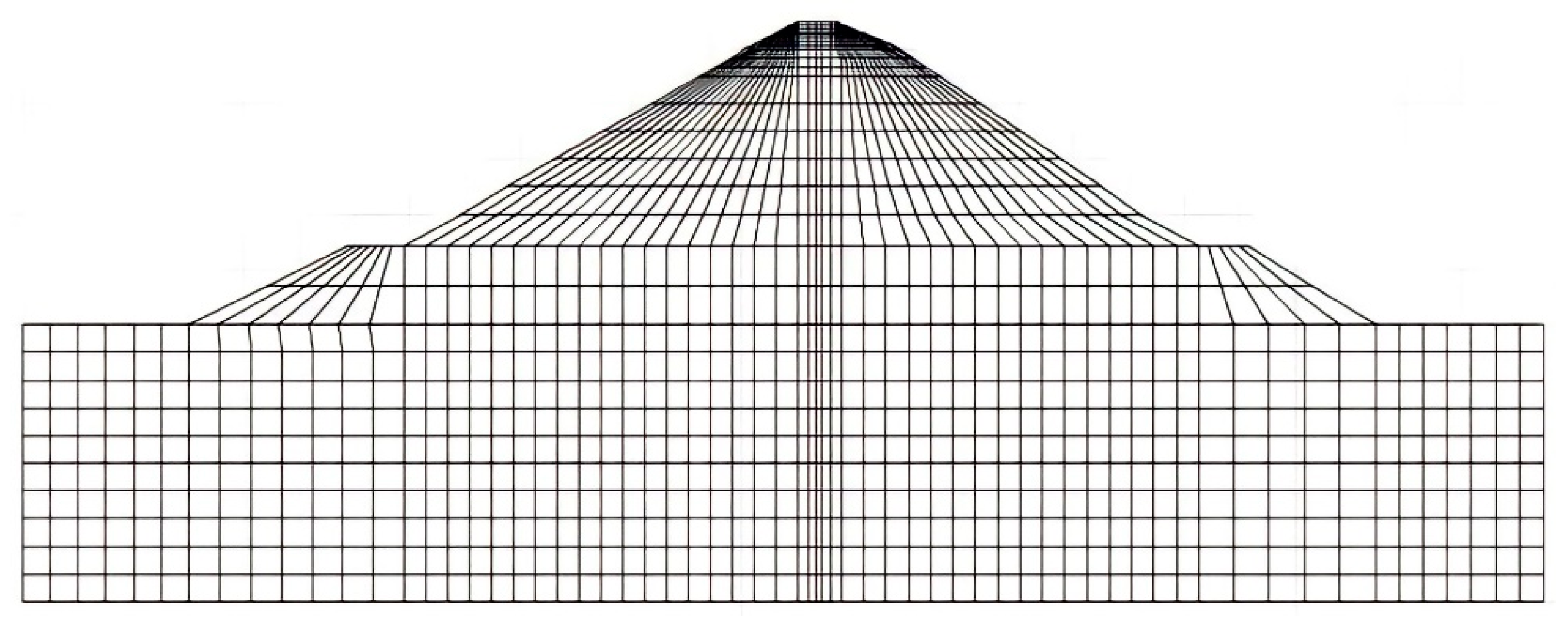
The first stage of the loading of the dam is its construction stage. Because the dam’s foundation is also modeled in the analysis, the initial analyses are performed to determine the initial stresses. The dam’s body is built in 25 layers to model the dam’s behavior more realistically. The construction of the asphaltic core element also proceeds at the same time as the construction of the body.
After the construction of the dam, loading was exerted by water. The water level was increased in three stages to reach 46 m in height. During impounding, hydrostatic force is applied on the asphaltic impermeable core.
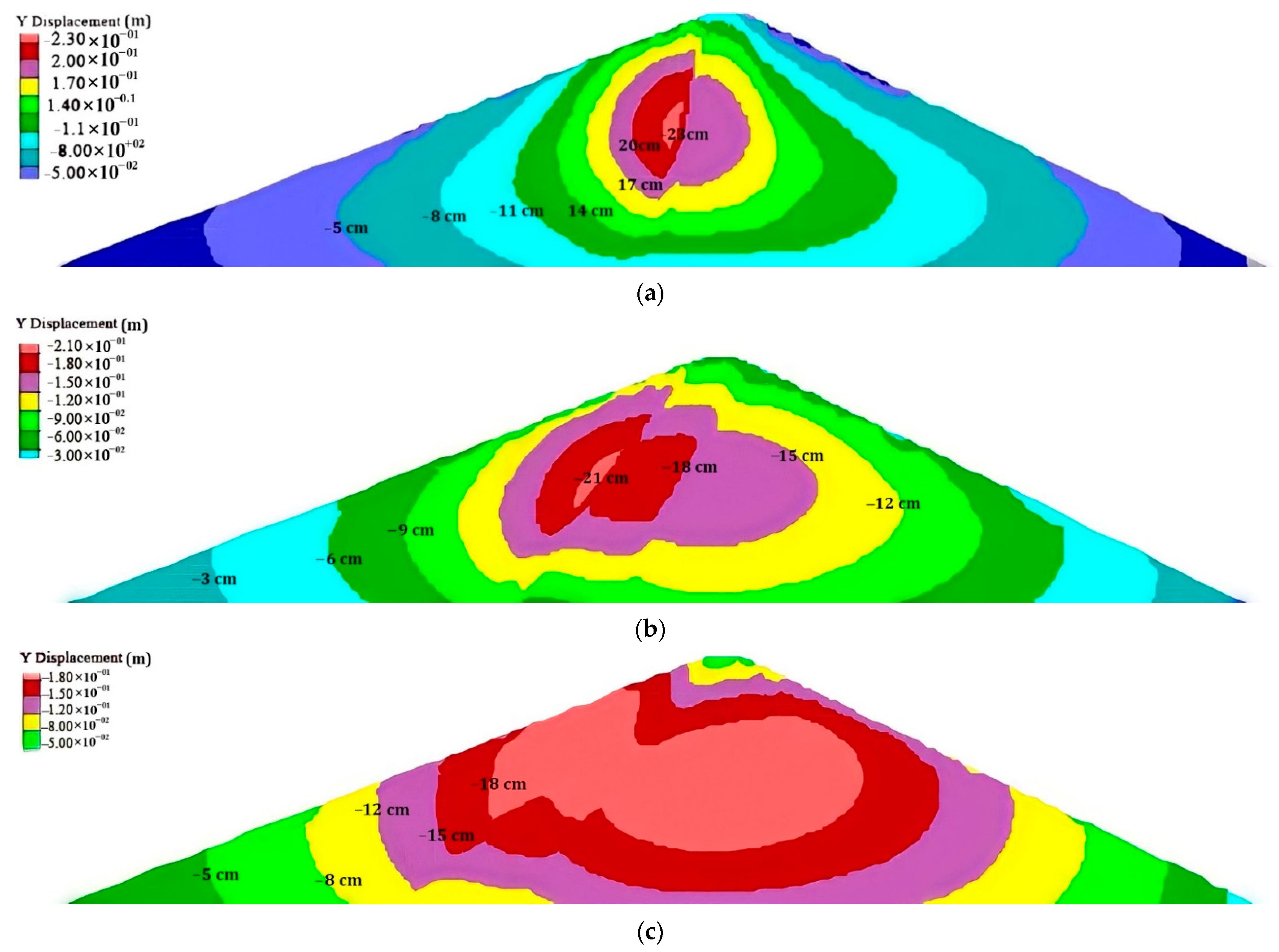
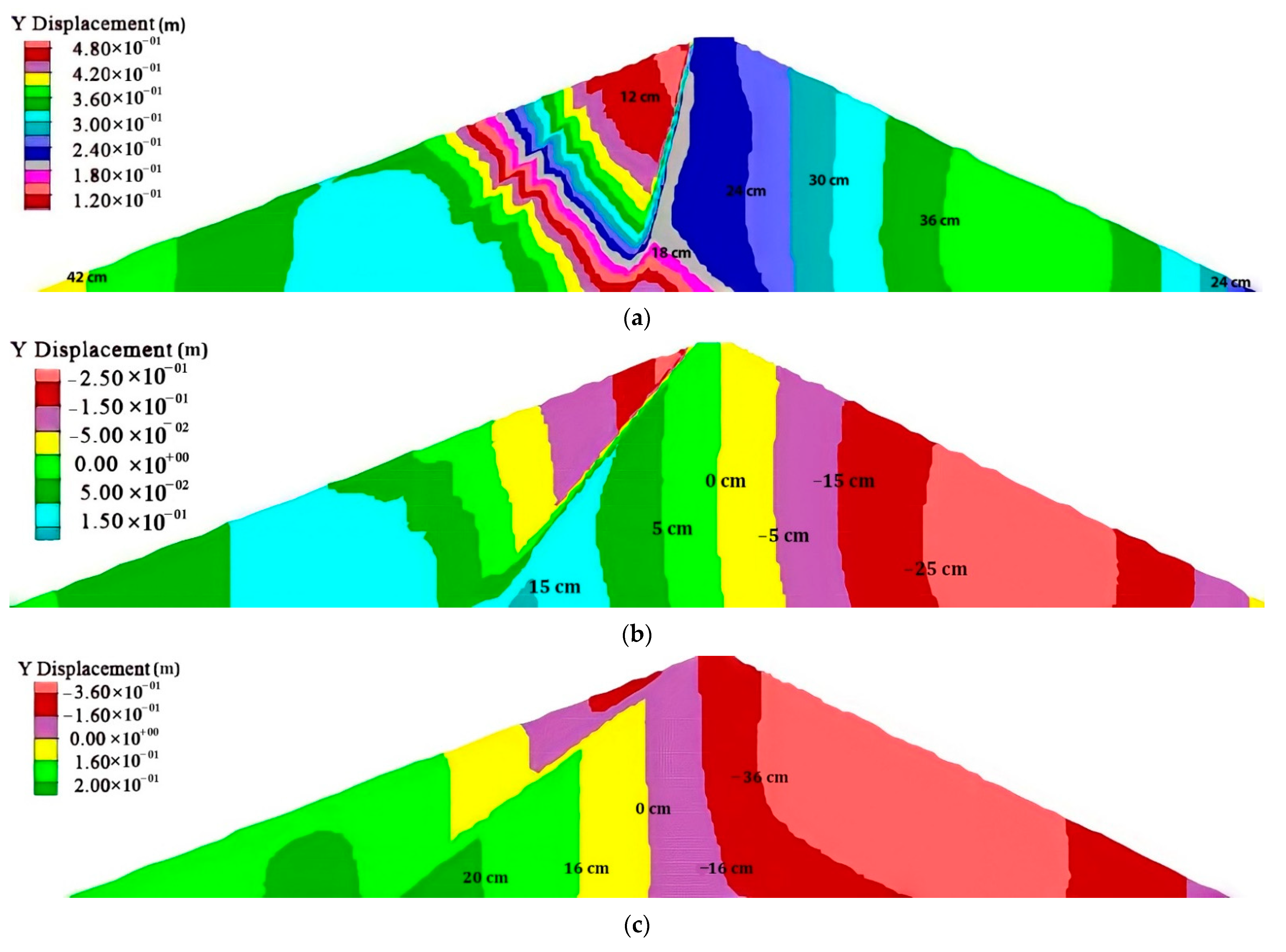
Figure 4 represents vertical displacement at the end of the impounding stage. At this stage of loading, water forces are applied to the asphaltic core and cause it to move downwards. In all three models, the maximum vertical displacement occurred in the core region and the middle part of the height because the core material’s elastic modulus is not the same as the shell material. The maximum settlement is near the boundary between the shell and the core in the shell region and decreases as it moves towards the slope. Another reason for settlements in the upstream shell is due to the loss of cementation between some grains or their local crushing. However, due to the lack of a suitable model, the effect of this phenomenon was not considered in the analyses. Moreover, due to the saturation of the upstream shell and the change of its density to the immersion state, uplift forces are created in the upstream shell and cause it to move upwards in all three models. As observed in
Figure 4, in the dam with a vertical core, the maximum settlement is about 23 cm, and in the cores with angles of 60° and 45°, it is 21 and 18 cm, respectively, which shows that the amount of settlement decreases as the core becomes more inclined.
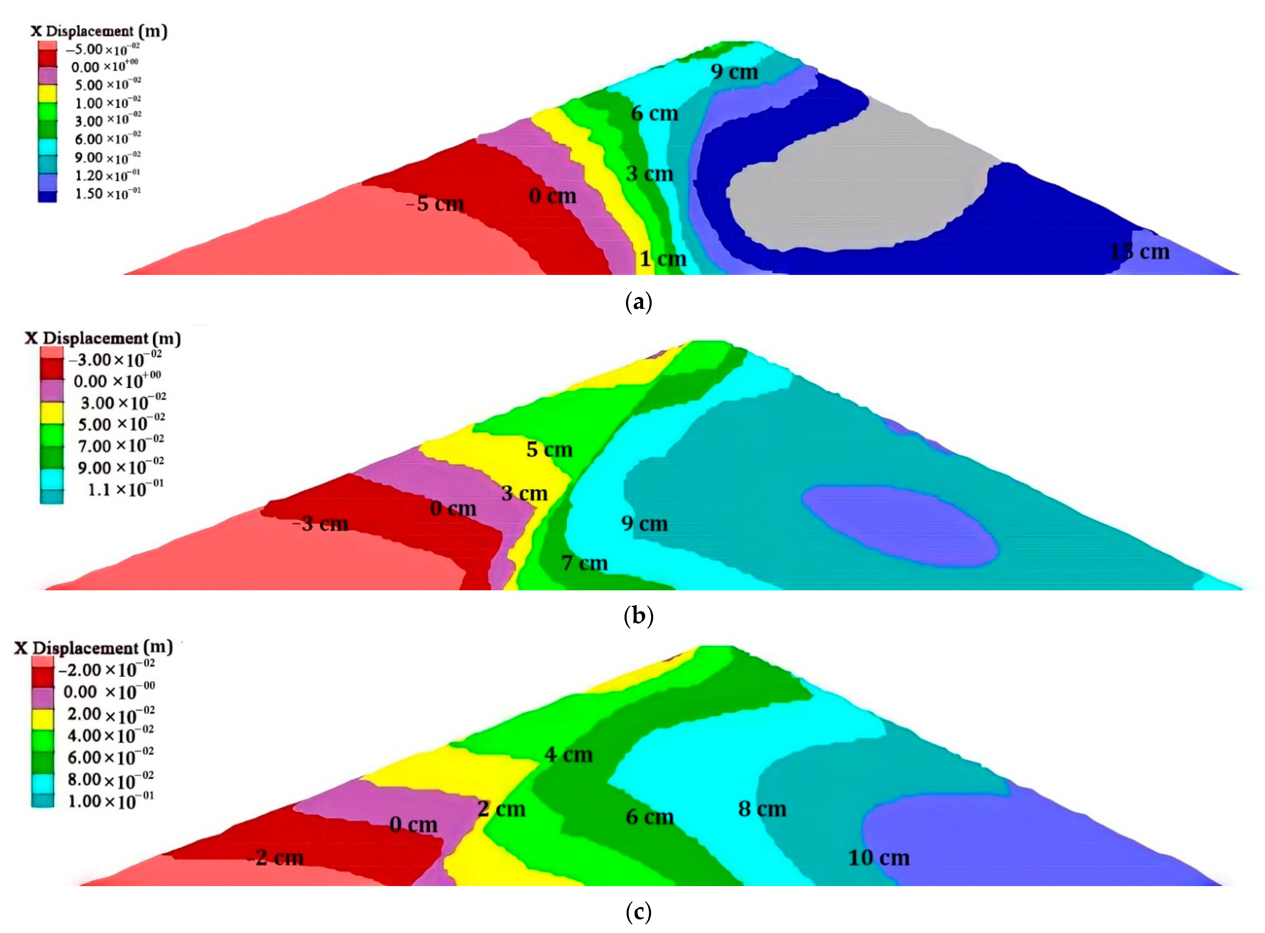
Figure 5 shows the horizontal displacement. As observed, the maximum values of horizontal displacement also decrease with the inclination of the core. The values of horizontal displacement increase as it moves from upstream to downstream due to the weight of water behind the dam in the static analysis. The maximum horizontal displacement will occur in all three models on the downstream side. Relatively low horizontal displacement values (maximum 15 cm in the vertical core dam) indicate the stability of the three models of the dam under static loading.
3.2. Dynamic Analyses
All dynamic analyses were performed at the impounding stage using the equivalent linear model with FLAC 2D software. The Mohr–Coulomb constitutive model is used for all materials, including the asphaltic concrete, filter and shell. The dam is located in a region with very high seismicity and the maximum design earthquake (MDE) that can occur is 0.5 g. According to the type of soil at the dam site, the Friuli earthquake is suitable for seismic analyses, which is selected from the Peer Earthquake Database [
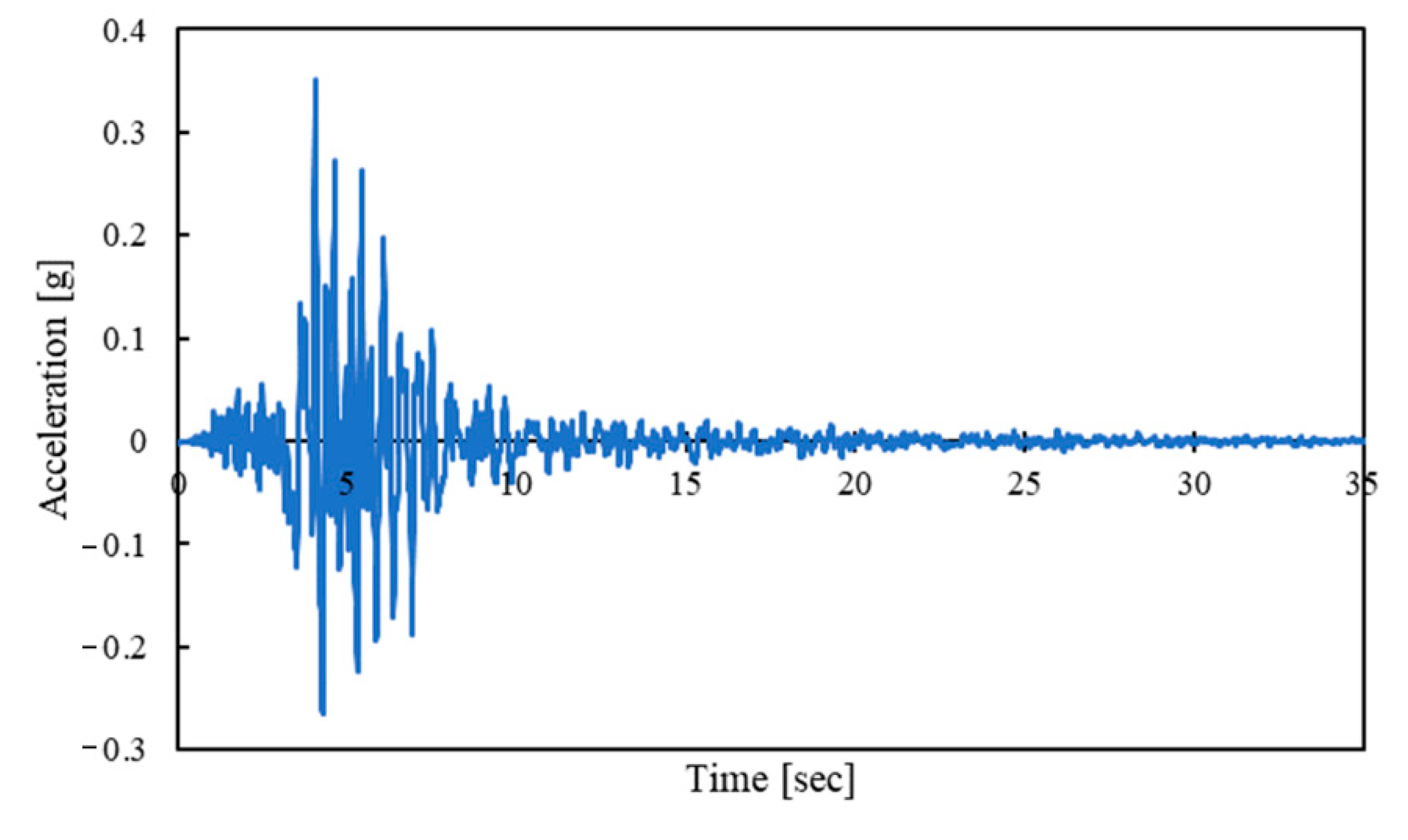
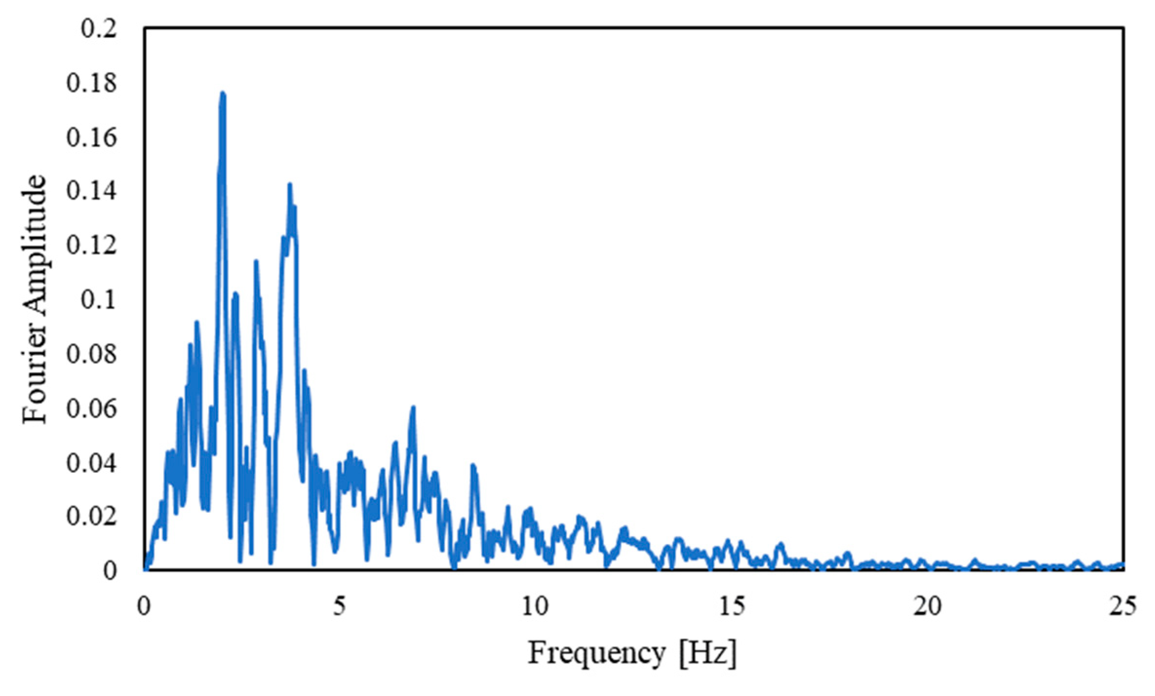
29]. This earthquake occurred in 1976 with a magnitude of 6 on the Richter scale in Italy, and its maximum horizontal acceleration was 0.35 g, which is scaled to the value of 0.5 g.
Figure 6 and
Figure 7 show the accelerogram and frequency range, respectively. One of the important issues when performing dynamic analyses is setting the boundary conditions of the model. In cases where the propagated waves, especially in the horizontal direction, are subjected to geometric attenuation, the boundary conditions must be chosen realistically. In FLAC software, some tools have been considered for this issue, which use it to minimize the effect of geometric damping. The use of free field boundaries is one of these capabilities that has been used satisfactorily when performing analyses. Selective acceleration is applied at the beginning of the elements and at the model’s base.
Figure 8 shows the earthquake-induced settlement in the dam for three different core angles. The maximum settlement in these three models occurred on the upstream shell and near the dam’s crest. This settlement is at the boundary between the core and the upstream shell and causes a vertical displacement in a positive direction (uplift) on the upstream slope. In contrast, on the downstream slope, a small settlement happens. Comparison of the maximum amount of vertical displacements in the three models also shows better performance of the dam with an inclined core than the vertical core. However, the settlement decrease does not continue for the most inclined core, which could be due to the increase in pore water pressure on the upstream side. In the 60° core, the settlement is minimal and indicates the optimal situation. Moreover, it can be said that an unequal settlement has occurred between the core and the upstream transition regions. The reason for unequal settlement on both sides of the core can be explained by the fact that due to the saturation of the upstream shell and the presence of pore pressures; the effective stresses in this region are less than the effective stresses in the downstream shell. Therefore, the yield surface according to Mohr–Coulomb is lower and leads to more settlements. Swissgood studied 69 rockfill and embankment dams and proposed an equation for crest settlement prediction [
30]. This equation requires only the magnitude and maximum acceleration of the earthquake. Based on this equation, the expected settlement for the Meijaran dam is 3% of the dam’s height or 1.63 m, which is very different from the results of the analyses and is about 3.4 times bigger. This means that the prediction of crest settlement does not depend only on the acceleration and magnitude of the earthquake but also on other factors such as distance from the earthquake, type of dam, etc.
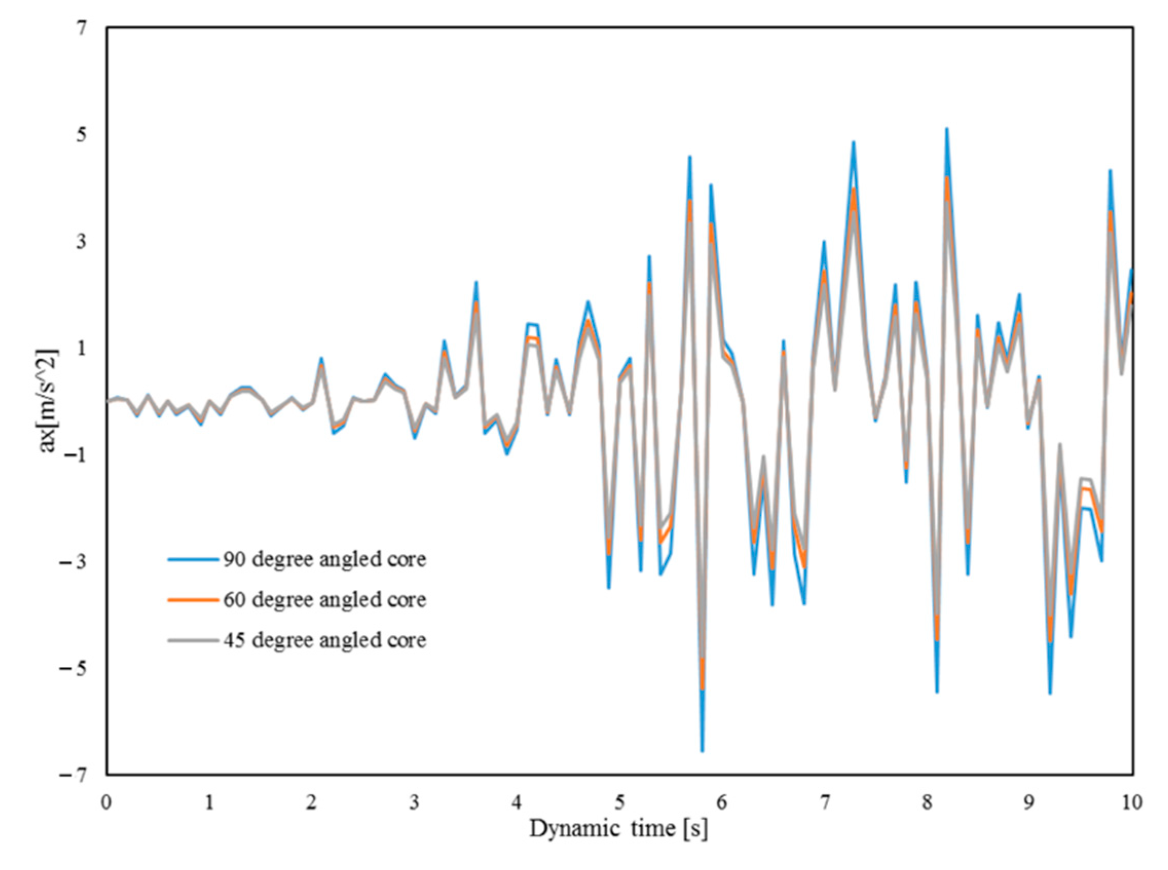
Induction acceleration in the dam’s crest in three models is shown in
Figure 9. Induction acceleration is the ratio between the acceleration of the crest to the acceleration of the base. Induction accelerations vary in different materials and specific geometric conditions. By further studying these accelerations, it was found that its values inside the asphaltic core are higher than in other parts of the dam body. In the core, the values of induced accelerations increase with increasing height, and they reach their maximum near the dam’s crest. Based on
Figure 9, the maximum expected acceleration in vertical core occurred in the dam’s core and its value is about 0.66 g, which indicates an amplification factor value of 1.88. Induction acceleration in the 60° core is 0.54 g, which indicates amplification of 1.54. In the core with a 45° core, it is equal to 0.48 g, which indicates an amplification of 1.37. The acceleration spectrum response analysis results also show a better performance of inclined core dams than vertical core dams. In all three models, the maximum acceleration occurred in the sixth second.
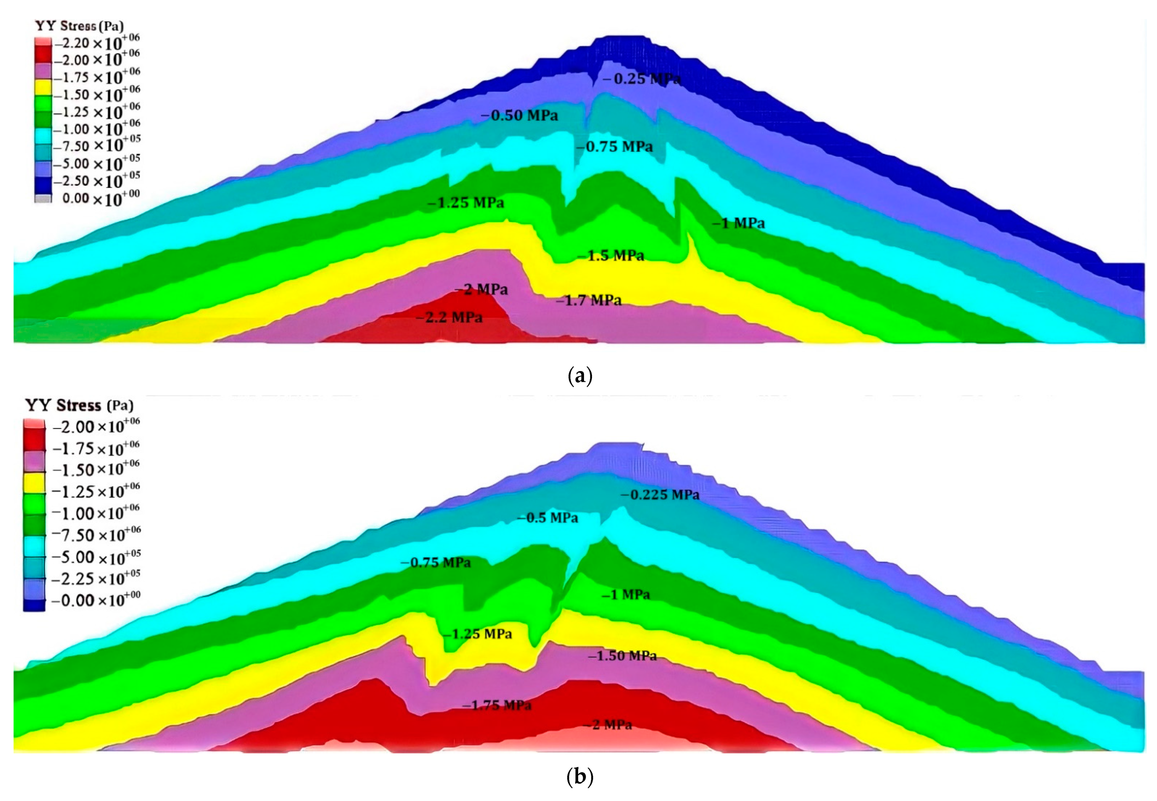
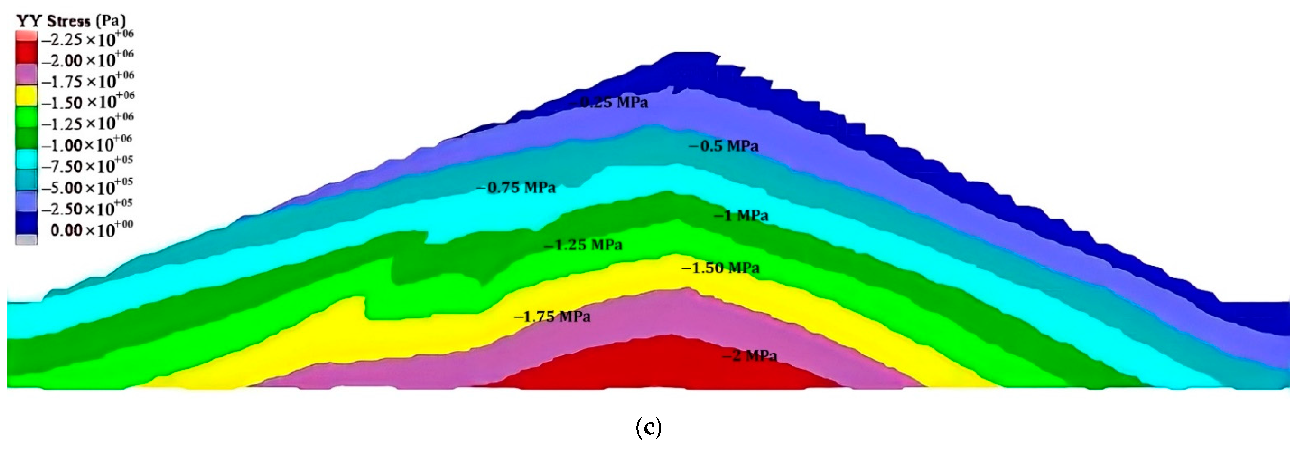
The images in
Figure 10 provide the contours of vertical stresses during earthquake loading. The maximum values of total vertical stress in all three models are approximately 2.2 MPa. The total stresses of the core are higher than in other parts of the dams. However, these stresses are such that the core remains in an elastic state and no issues occur for the dam’s core. Typically, with increasing depth, the values of stresses increased, and the maximum stress occurs in the bed of the foundation.
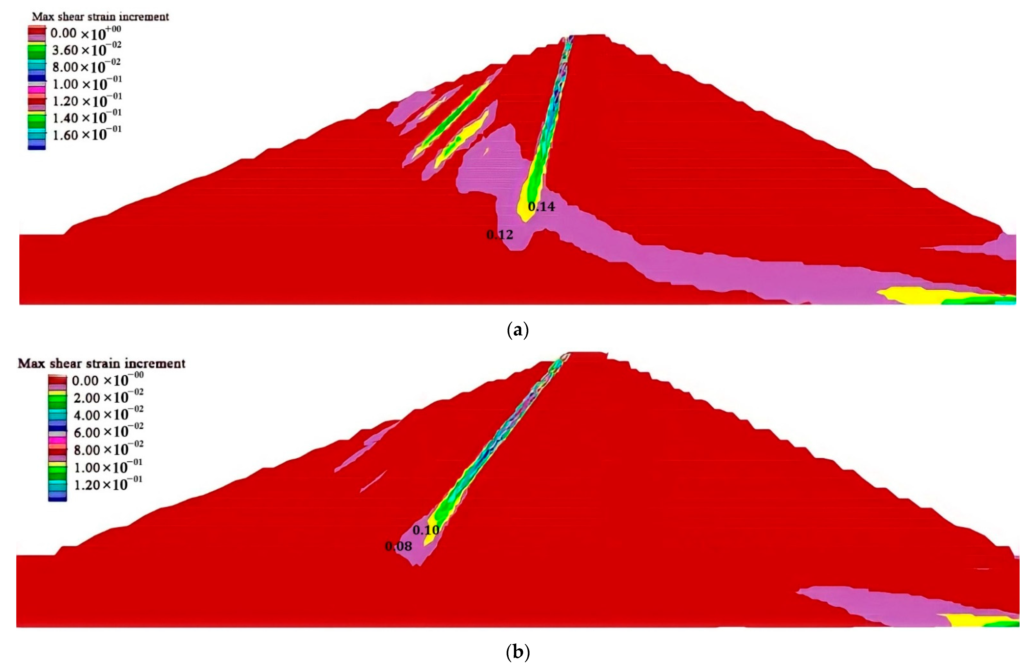
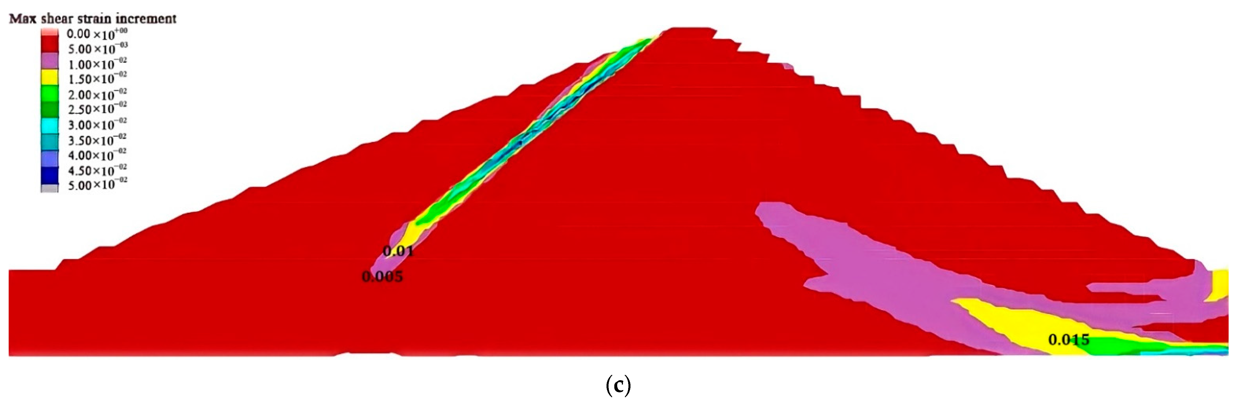
Figure 11 shows how the strains were distributed in the dam body during the Friuli earthquake simulation. The maximum shear strain in the dam with vertical core is equal to 1.6%, which decreases with the inclination of the core so that, in the dam with the most inclined core, the maximum shear strain is 0.5%. The maximum values occurred at the core boundary with the upstream shell due to the reduction in shear strength of the upstream shell due to water and noticeable differences in the properties of the core and shell materials. In the three models, the strains that occurred are less than 1.6%, and shear failure does not occur.
4. Comparison of Numerical and Experimental Results
For a better view, the results of centrifuge tests performed by Baziar et al. [
31] are compared with numerical dynamic results obtained by simulation of the Meijaran dam in FLAC 2D software. The centrifuge tests performed by Baziar were performed on samples with a vertical core. As indicated above, the Mohr–coulomb constitutive model was used in these analyses. As shown in
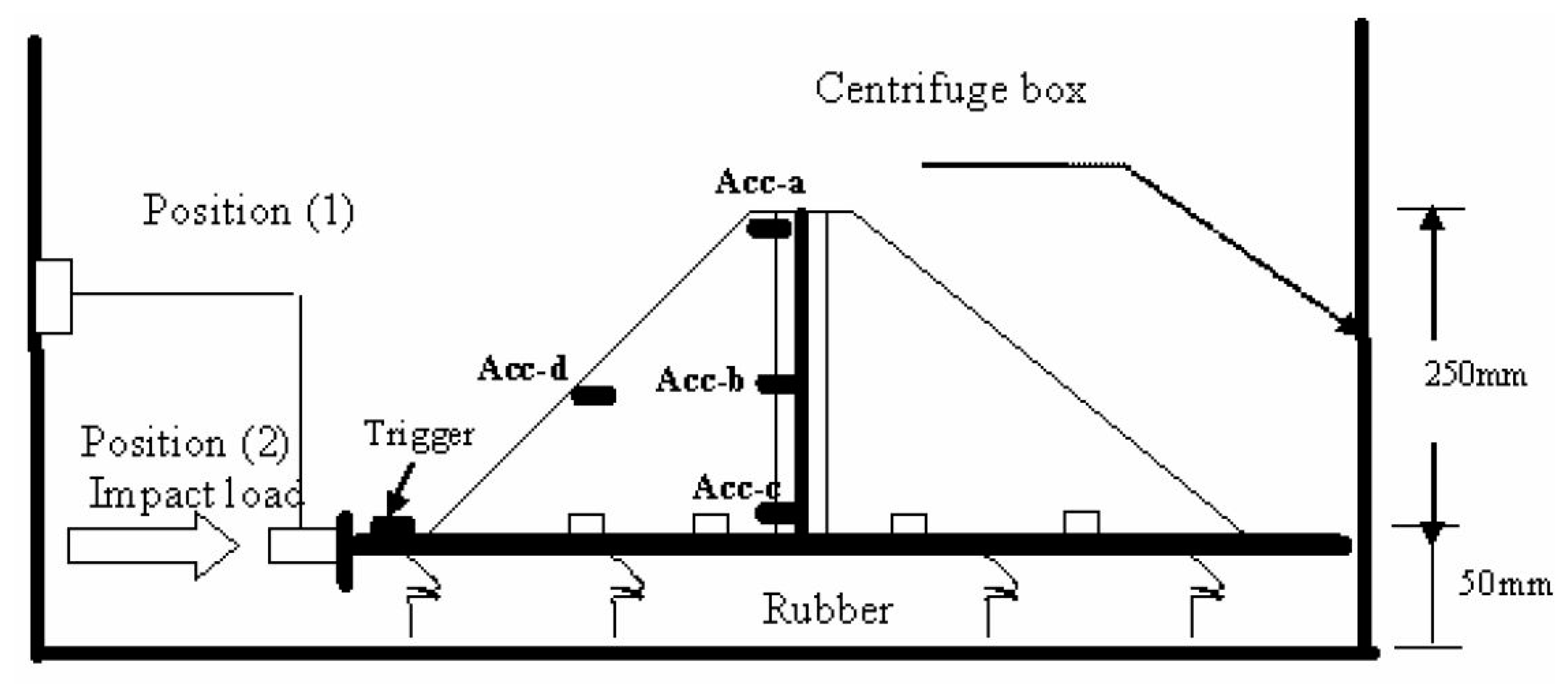
Figure 12, the centrifuge models are 25 cm high and 90 cm wide at the base. The vertical asphaltic core is 1 cm thick and is manufactured as a pre-cast panel. These models are a 1:80 scale simulation of the Meijaran rockfill dam with an asphaltic concrete core.
Baziar et al., conducted five separate tests for different centrifuge accelerations. In this paper, the centrifuge test results with 80×
g acceleration are used because the test performed with this acceleration had low error rates and is very similar to the Friuli acceleration [
32].
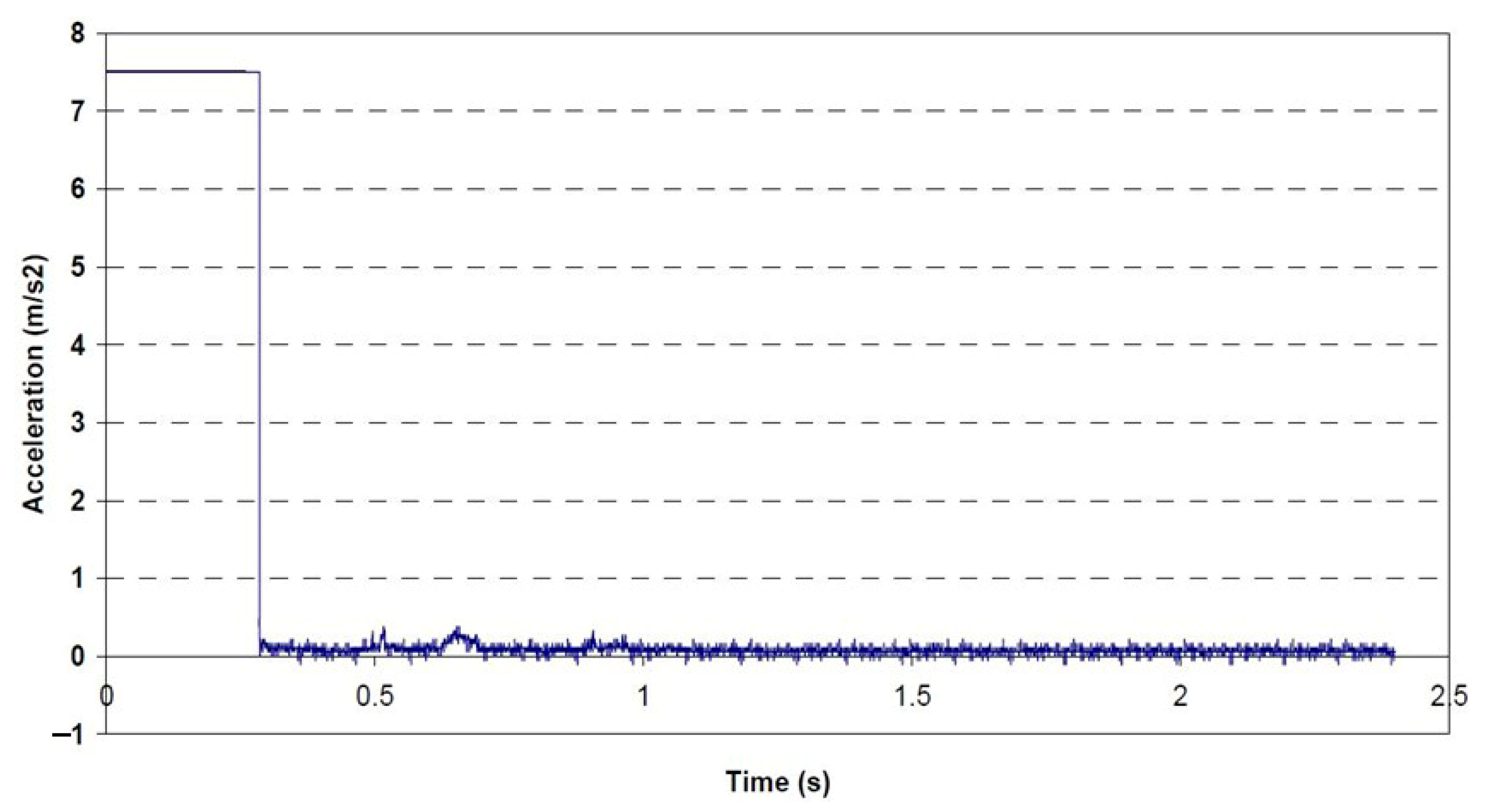
Figure 13 shows the input motion by an impact load in 0.30 s with a large acceleration of 7.6 m/s
2.
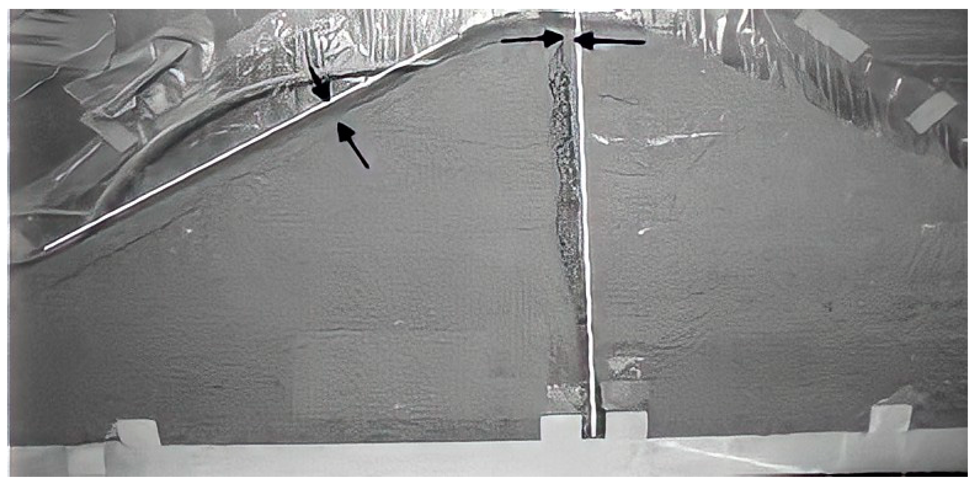
The results of the test observations and the model show that the deformations created in different parts of the dam are very small and also no sliding or failure has occurred in the dam body. Data monitoring shows that a 9 mm settlement is induced under static and dynamic loading (scaled at 1:80) at the top of the asphaltic core. As cobservedin
Figure 14, the lateral displacement of the asphaltic core increases from the bottom to the top so that its maximum at the dam crest is 8 mm (under static and dynamic loading). Moreover, a maximum shear strain of 1.8% occurs in the asphaltic core under impact loading.
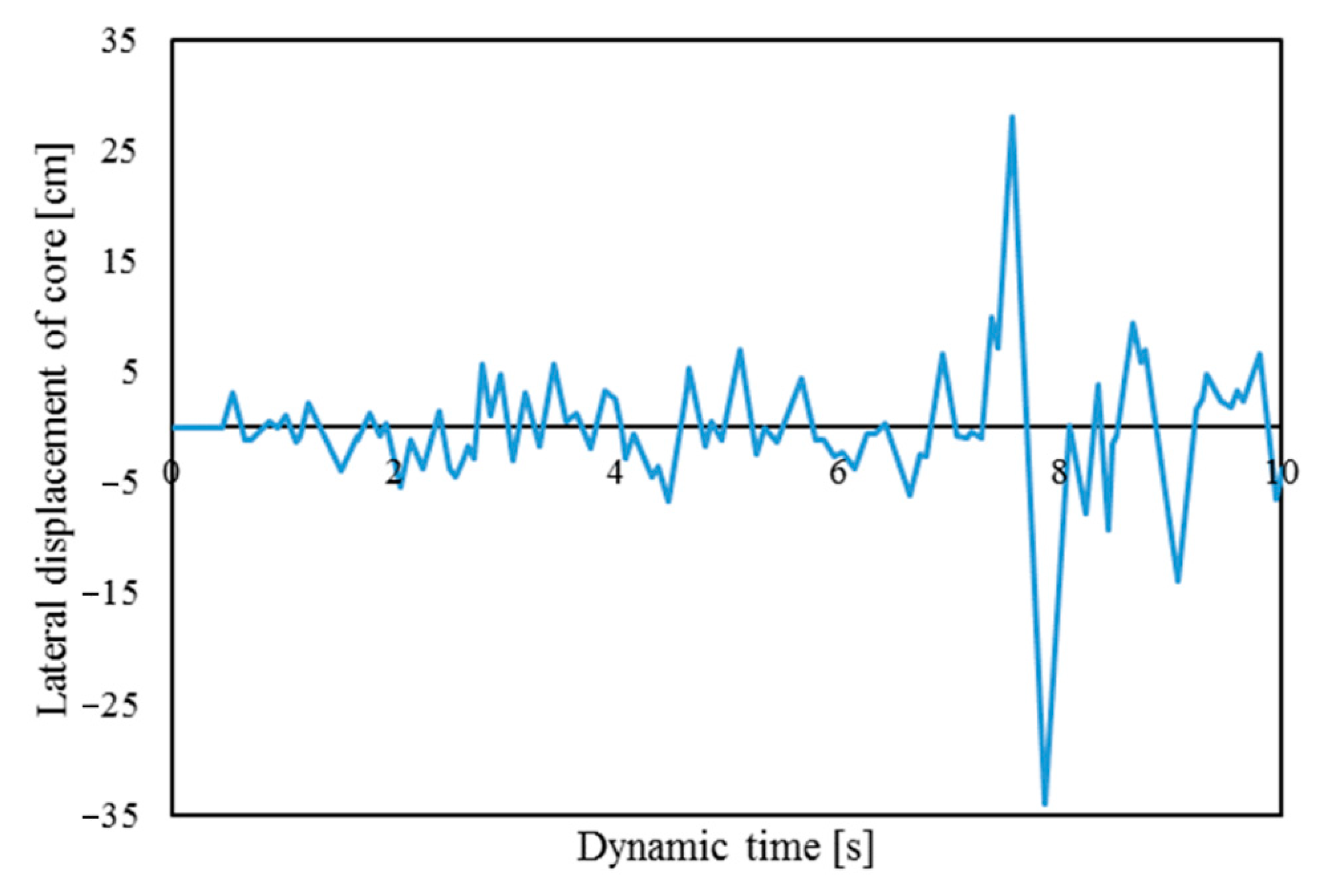
Figure 15 shows the values of lateral displacement in the dam with vertical core due to seismic load.
Figure 11a and
Figure 15 are compared with the centrifuge test results. The numerical analysis results using FLAC2D software are very similar to the results obtained from the centrifuge tests.
Table 2 shows the induced deformations in the experimental and numerical results under dynamic loading. A comparison of the results shows very little differences between them. Any differences may be due to faults in the laboratory tests and can be ignored.


 ,
, 


