1. Introduction
With steel-bar reinforced concrete (RC) having become the
par excellence solution in structures in the last century, the possibility of partial or even total substitution of steel-bars by steel fibers would not only allow the cost of a structure to be reduced but also provide certain other improved properties. Once such substitution has been accepted as viable, it will boost industrial development and research on fibers. Hence, new fiber types, with various shapes and constituent materials have emerged [
1,
2,
3].
The production of steel fiber-reinforced concrete (SFRC) requires the use of materials, admixtures and special operational technology that inevitably increases the cost of the composite material. This is the reason why it is only profitable when enhanced structural properties are required. Some applications, such as pavements and tunneling, often need special requirements that can be achieved by using SFRC (although it has also been employed to meet other structural demands) [
4,
5]. As SFRC has become more popular in building and civil construction, some constitutive models, design approaches and tests have been developed [
6,
7,
8,
9,
10,
11,
12]. Hence, the challenges of FRC are now based on the best exploitation of the materials and the optimization of the fibers and matrices in order to produce the most suitable composite material for a specific purpose [
13].
Not only the good performance of steel combined with concrete, but also its drawbacks have been widely reported. Some such drawbacks vary from corrosion to high purchase, storage and handling costs. The durability of SFRC has concerned not only engineers but also industry in general. In response to this, the evolution of the plastic industry has allowed chemically stable fibers with improved mechanical properties to be produced [
14]. Recently, efforts made in the plastic industry have focused on achieving a new generation of polyolefin based synthetic macro-fibers that are not only inert in an alkaline environment but also offer structural benefits [
15]. Such macro-plastic fibers decrease the workability of the fresh concrete to a lesser extent when compared with SF and have no obvious effect on the compressive strength, tensile strength and modulus of elasticity, all of which are dominated by the concrete matrix properties [
16]. Hence, the main benefit of using polyolefin fiber-reinforced concrete (PFRC) lies in the excellent post-cracking behavior which, together with cost and environmental benefits, makes it an attractive alternative to conventional steel reinforcement in the construction industry. Plastic fibers can significantly reduce the overall cost of the material and permit the corrosion problems that appear with SF to be avoided. Moreover, some reductions in the carbon footprint, when compared with that of producing steel, have also been reported [
17]. In summary, the use of macro-plastic fibers to reinforce concrete instead of use of steel mesh and steel fibers has become appealing to scientists, the concrete-related industries with polyolefin-based fibers being the most common. Therefore, published research has reported that polyolefin-based macro-structural fibers are especially well-suited for infrastructure applications such as the construction of pavements, light precast elements and tunnel linings [
18].
However, there is limited published research into a fracture behavior that allows a more reliable use of PFRC in infrastructure applications. It is worth noting that the residual load-bearing capacity is measured by fracture tests. That is to say, the definition of a structural fiber depends on the fracture behavior. As PFRC not only has considerable residual tensile strengths but also meets the requirements of the standards; the contribution of its fibers may be considered in structural design [
19]. Even though extended research is still required for a better comprehension of the potential of PFRC, promising results obtained from examination of PFRC have been published [
16,
20,
21,
22] and structural applications reported [
14,
23]. These references both show the possibilities of polyolefin-based macro-fibers as the only reinforcement of concrete and sustain the need of deeper research for a better comprehension of the fracture behavior of PFRC.
This paper supplies significant experimental results that permit PFRC to be considered for total or partial substitution of a steel bar. In addition, it helps to localize the respective weak points and proposes a combination of fibers that are proven to have synergistic effects. In summary, PFRC is shown to have considerable residual tensile strengths and to meet the requirements of the standards in considering the contribution of the fibers in structural design [
19].
This research is of direct significance as regards the characterization of PFRC in a fresh and hardened state and, more specifically, the respective fracture properties and residual capacities. However, the selection of the optimum fiber cocktail is significant after having proved the individual contributions. Both such an optimum definition of the proportions and fiber type were carefully chosen. In this sense, the combination of various types of fibers opens a promising field for new research that may provide significant results. Future designing of FRC could be focused on selecting the optimum combination of fiber types and contents. The results of this paper support that future line of research with worthy perspectives.
2. Concrete Production and Fresh-State Properties
The component materials included Portland cement type EN 197-1 CEM I 52.5 R-SR 5 and a mineral admixture of limestone used as a micro-aggregate. This limestone powder (LP) had a specific gravity and Blaine surface of, respectively, 2700 kg/m
3 and 400–450 m
2/kg. The calcium carbonate content of the limestone powder was higher than 98%, and less than 0.05% was retained in a 45-µm sieve. A polycarboxylate-based superplasticizer named Sika Viscocrete 5720 with a solid content of 36% and 1090 kg/m
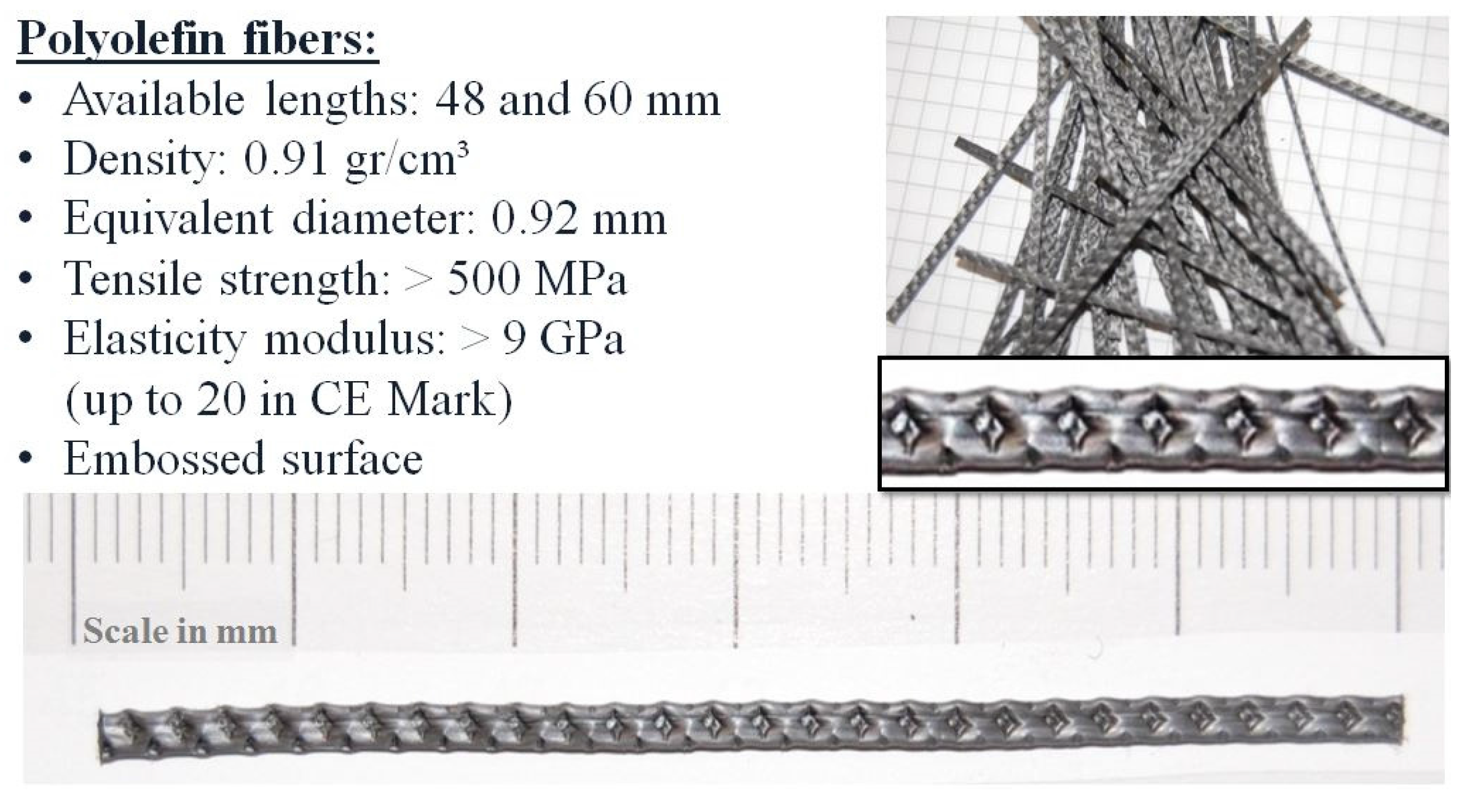
3 density was employed. The mixtures were made with siliceous aggregates composed of two types of gravel with a size of 4–8 mm and 4–12 mm and sand of 0–2 mm. The maximum aggregate size was 12.7 mm. Polyolefin straight fibers with a rough surface and surface treatment were employed with two lengths of 60 and 48 mm.
Figure 1 shows the main properties and the geometrical patterns of the fibers.
Figure 1.
Properties and visual aspect of polyolefin macro-structural fibers.
Figure 1.
Properties and visual aspect of polyolefin macro-structural fibers.
The SCC used was prepared and tested to meet the initial requirements of achieving a medium-strength concrete that maintains the self-compactability properties even after the incorporation of fibers. In order to do so, some initial trial mixtures were made to obtain a concrete mix design with as low a cement and admixture content as possible without harming its self-compacting properties when fibers were added. In these trial mixtures, up to 6 kg/m3 of polyolefin fibers were added to the mix.
For the paste design, the cement required was at least 375 kg/m
3 with 1.25% of cement weight of Sika Viscocrete-5720 admixture and a water-to-powder ratio of 0.50. The limestone powder addition remained at 200 kg/m
3, with the paste representing 38% of the total concrete volume. The proportions of the aggregates were those obtained for the maximum dry packing density, shown in
Table 1, and represented 25.5% of voids. The humidity of the aggregates was corrected before the manufacture of the concretes. The time schedule followed is also shown in
Table 1.
Table 1.
Proportion of aggregates for dry maximum packing density and mixing procedure.
Table 1.
Proportion of aggregates for dry maximum packing density and mixing procedure.
| Proportion of Aggregates for Dry Maximum Packing Density |
|---|
| Aggregate | Value (%) |
| Gravel | 24 |
| Grit | 16 |
| Sand | 60 |
| Mixing procedure | |
| Process | Duration of mixing process (s) |
| 1. Homogenization of aggregates | 60 |
| 2. Add 1/3 of fibers and mix | 30 |
| 3. Add cement and limestone powder | 30 |
| 4. Add 1/3 of fibers and mix | 30 |
| 5. Add 75% of the mixing water and mix | 30 |
| 6. Add 1/3 of the fibers and mix | 30 |
| 6. Add 25% of the water with superplasticizer | 240 |
| 7. Rest (superplasticizer acting period) | 150 |
| 8. Final mix | 120 |
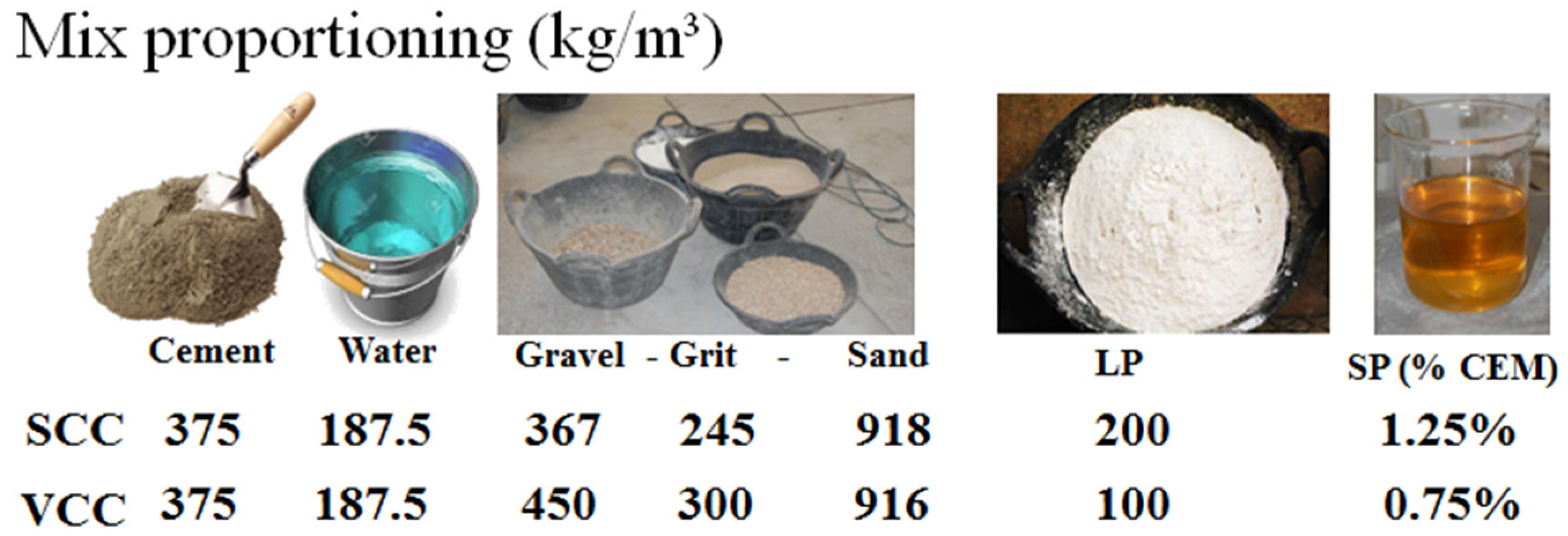
On the basis of the SCC mix proportioning, a conventional concrete was designed with the challenge of providing analogous fracture energy to the plain concrete. In the fracture tests, after the limit of proportionality was reached, the inelastic processes of plain concrete fracture barely contributed to preventing the collapse of the piece. Nonetheless, analysis should evaluate the energy added by fibers and the structural behavior in the post-cracking region of the curves. In such a case, the fracture energy and residual load-bearing capacity of the plain concrete should be near to each other. The mix proportioning of both types of concrete, SCC and VCC, can be seen in
Figure 2.
Through use of SCC and VCC, and with the aim of comparing the behavior with each other, two batches of each mixture with 0, 3, 4.5, 6 and 10 kg/m
3 of 60mm-long polyolefin fibers were produced. Hence, five SCC mixtures were named respectively as SCC, PFR-SCC3, PFR-SCC4.5, PFR-SCC6 and PFR-SCC10. The corresponding five mixtures that used VCC were, consequently, named as VCC, PFR-VCC3, PFR-SCC4.5, PFR-SCC6 and PFR-SCC10. One more mixture was manufactured with 10 kg/m
3 that also used a bond improver admixture named Sikatell 250 (see Reference [
16]). The latter was named PFR-SCC10M.
Figure 2.
Mix proportions of the plain SCC and VCC used as reference for the mixtures of FRC.
Figure 2.
Mix proportions of the plain SCC and VCC used as reference for the mixtures of FRC.
Two mixtures were defined in the initial step with the aim of comparing the results of PRCF with those using 35 mm-long steel-hooked fibers and the SCC formulation. These two mixtures were labeled as SFR-SCC26 and SFR-SCC39. The SF dosages were chosen to coincide in terms of volume fraction with the relative proportions of PFR-SCC3 (0.33%) and PFR-SCC4.5 (0.49%). Finally, a hybrid mixture was defined using 26 kg/m
3 of SF, plus 4.5 kg/m
3 of PF added to the SCC formulation. The latter is described in more detail in
Section 5 of this paper.
With each type of concrete, two prismatic specimens of 600 × 150 × 150 mm3 and nine cylindrical specimens with a height of 300 mm and diameter of 150 mm were cast. All the specimens were stored at room temperature for the first 24 h and then kept in a climatic chamber at 20 °C and 95% of relative humidity for 28 days until the age of testing.
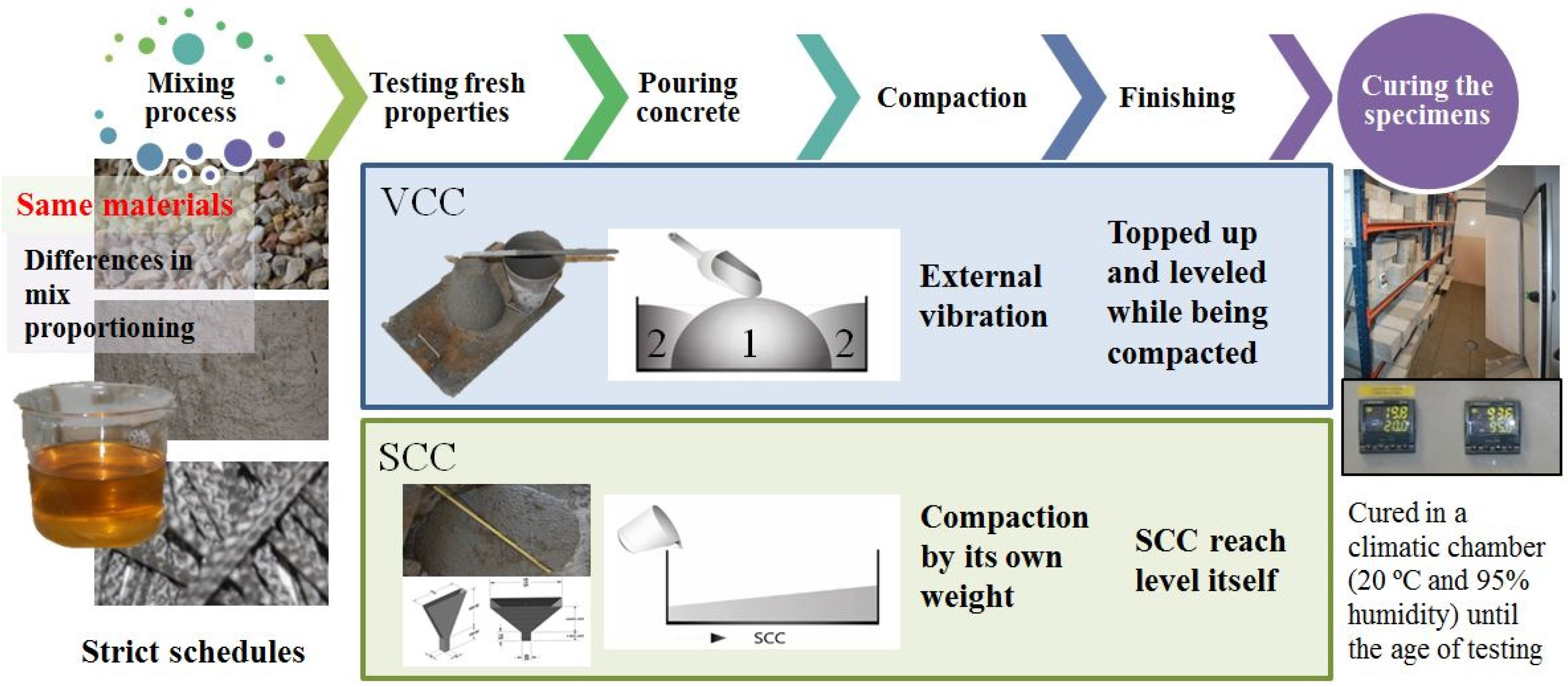
Concerning the pouring methods, in the SCC mixes all the specimens were filled in a single pour from one of the sides of the mold. The specimens were subsequently compacted and levelled off by the action of the own weight of the fresh concrete. Those specimens prepared with VCC were compacted for 10 s by means of a vibratory table and filled following the procedure stated in the standards [
10]. That is to say, molds were filled initially in a central portion of approximately 90% of the height of the specimen and two portions in the half side of it. Then, the mold was topped and levelled while being compacted. Both consolidation processes might affect the distribution and orientation of the fibers and, as a consequence, the fracture behavior of the specimens. These issues and the difference in the procedures can be seen in
Figure 3.
Figure 3.
Main processes of SCC and VCC concrete production.
Figure 3.
Main processes of SCC and VCC concrete production.
The fresh-state behavior of SCC mixes, with or without fibers, was assessed by using the slump flow test [
24] and the V-funnel test [
25]. The results can be seen in
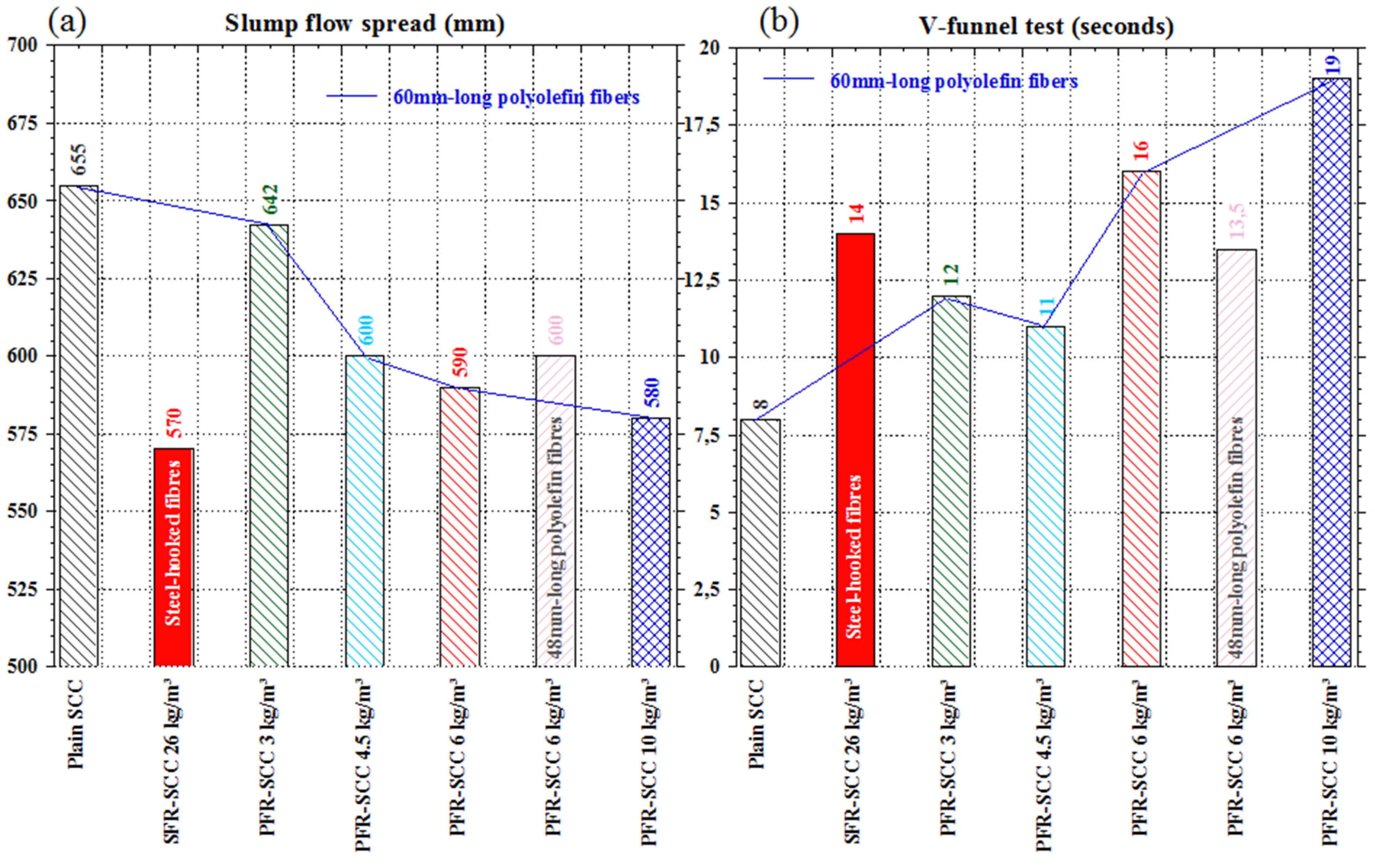
Figure 4. The slump flow spread tended to decrease as the amount of fibers increased. In the same sense, the emptying times of the V-funnel test increased proportionally with the fiber dosage. Moreover, there was a subtle influence of fiber length. However, the comparison with the influence of steel-hooked short fibers in mixture SFR-SCC26, which corresponds in volume fraction to the formulation PFR-SCC3, showed the good performance the polyolefin fibers. The latter can be easily observed in
Figure 4 and explained by the non-rigid nature of the fibers.
Figure 4.
Fresh-state results with several fiber dosages: (a) Slump flow spread diameter; (b) V-funnel emptying times.
Figure 4.
Fresh-state results with several fiber dosages: (a) Slump flow spread diameter; (b) V-funnel emptying times.
Regarding VCC mixes, the fresh-state properties of the concrete were addressed by means of the slump test [
26], whether the mixture had fibers or not. In order to obtain similar results in the latter test, the amount of superplasticizer used was increased in the VCC10 formulation from 0.75% to 0.82% with respect to cement weight. In consideration of such a modification, the results were around 15 cm of descent of the mass for all the formulations.
3. Evaluation of the Mechanical Properties
The compressive strength, modulus of elasticity and indirect tensile strength tests were performed by using the cylindrical specimens. All these tests were carried out following some of the most employed standards [
27,
28,
29], using three specimens at 28 days of age. The mean values of all the tests and the coefficient of variation (c.v.) can be seen in
Figure 5,
Figure 6 and
Figure 7 and
Table 2. The characteristic value of the compressive strength was computed by means of Equation (1) where σ is the coefficient of variation and
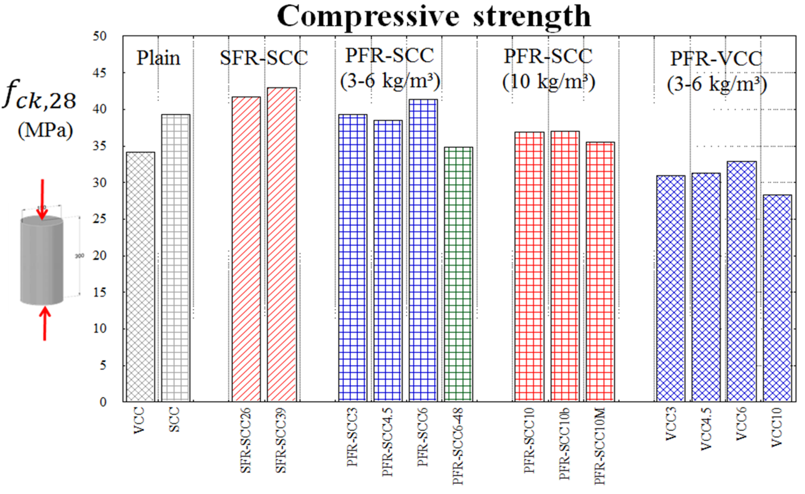
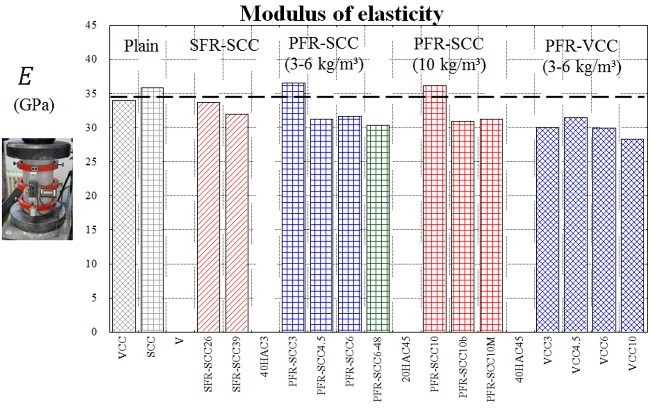
fcm the mean compressive strength obtained in the tests. No major changes were noticed in the modulus of elasticity of the SCC mixes. However, it would seem that the addition of fiber contents above 3 kg/m
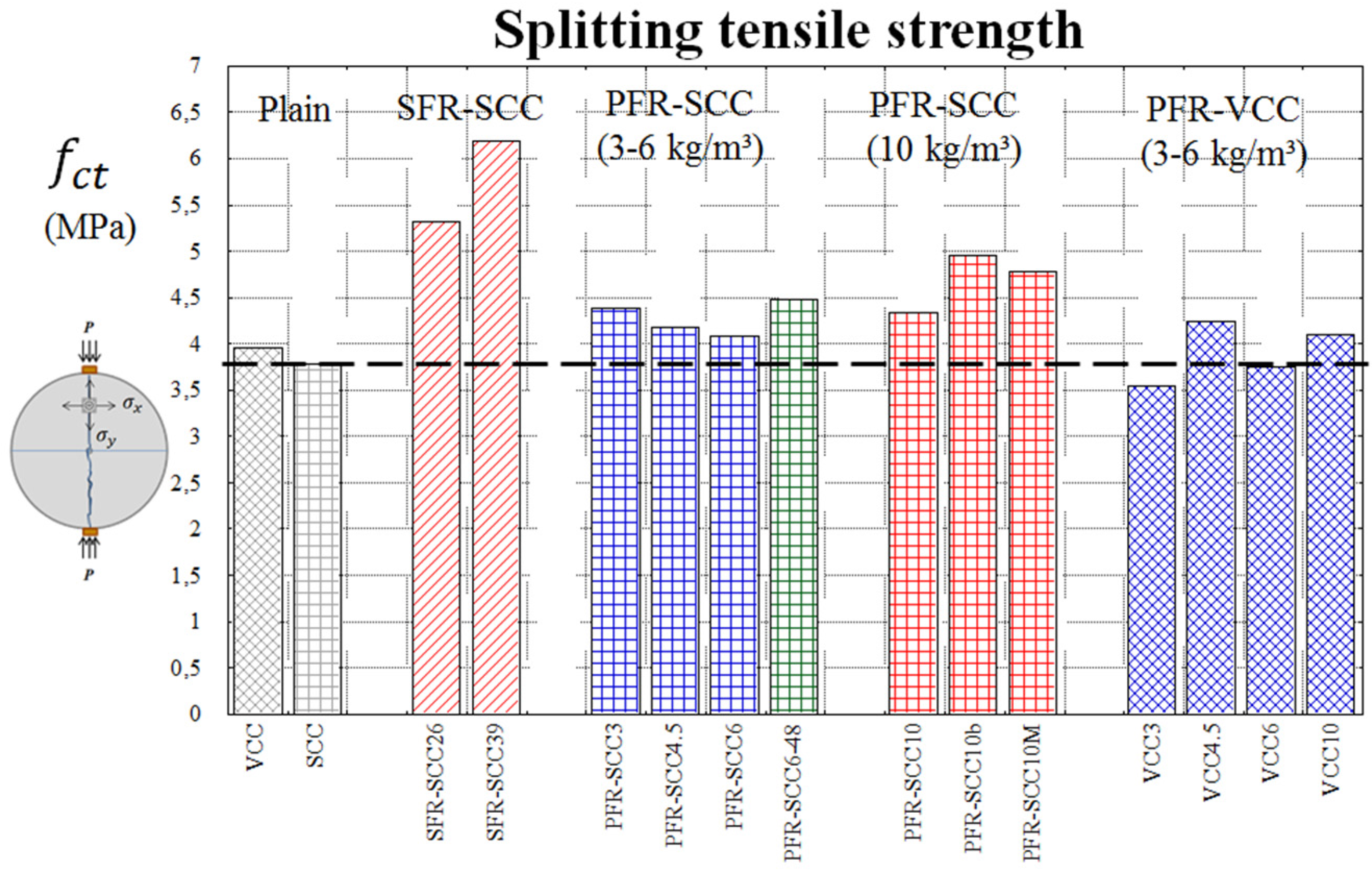
3 might worsen the compaction of the concrete in the molds and thus reduce the test results. A similar phenomenon might also take place in the VCC mixes. When the values of
fck and
fct were analyzed, no variations in the values obtained out of the boundaries of the typical experimental scatter were noted.
Figure 5.
Compressive strength.
Figure 5.
Compressive strength.
Figure 6.
Modulus of elasticity.
Figure 6.
Modulus of elasticity.
Figure 7.
Splitting tensile strength.
Figure 7.
Splitting tensile strength.
Table 2.
Mechanical properties of the polyolefin fiber-reinforced concrete (PFRC).
Table 2.
Mechanical properties of the polyolefin fiber-reinforced concrete (PFRC).
| Mixture | fck (MPa) | c.v. | fct (MPa) | c.v. | E (GPa) | c.v. |
|---|
| VCC | 34 | 0.04 | 3.9 | 0.10 | 34 | 0.04 |
| SCC | 39 | 0.01 | 3.8 | 0.14 | 36 | 0.03 |
| VCC3 | 31 | 0.02 | 3.6 | 0.03 | 30 | 0.03 |
| SCC3 | 39 | 0.01 | 4.4 | 0.09 | 36 | 0.06 |
| VCC4.5 | 31 | 0.07 | 4.2 | 0.12 | 31 | 0.07 |
| SCC4.5 | 38 | 0.06 | 4.2 | 0.20 | 32 | 0.01 |
| VCC6 | 33 | 0.04 | 3.9 | 0.07 | 30 | 0.06 |
| SCC6 | 41.4 | 0.01 | 4.1 | 0.03 | 32 | 0.02 |
| SCC6-48 * | 34.8 | 0.05 | 4.5 | 0.08 | 30 | 0.01 |
| VCC10 | 28 | 0.03 | 4.1 | 0.06 | 28 | 0.04 |
| SCC10 | 37 | 0.02 | 4.6 | 0.09 | 30 | 0.02 |
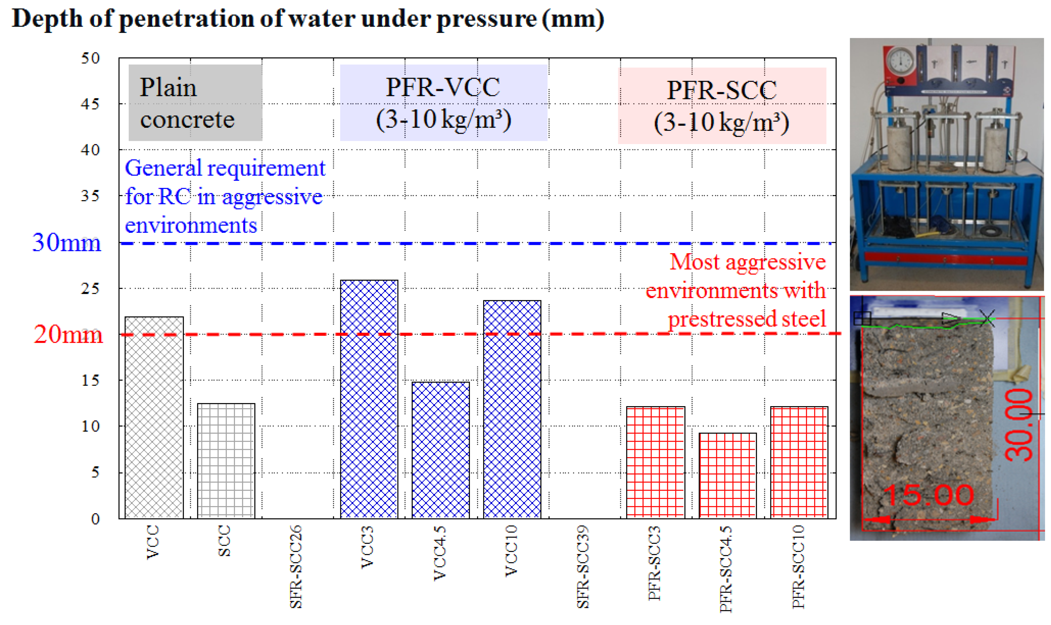
The durability performance was assessed by means of permeability tests according to the standard [
30], with the results being shown in
Figure 8. According to those obtained, the presence of fibers did not influence the connected porosity network of concrete. The value of the penetration of water under the pressure of all of the VCC mixes was greater than the equivalent formulation of SCC in all of the mixes. Therefore, it could be argued that the coarser aggregate skeleton of the VCC mixes is responsible for the more permeable pore structure. In addition, due to the limited depth of penetration, below 20 mm, all the mixes made with SCC were suitable for use in extremely harmful environments in accordance with EHE-08 [
8]. In contrast, VCC mixes (with depths of penetration below 30 mm) were apt for use in medium-hazardous environments (according to EHE-08) due to a more permeable porous structure. Subsequently, it was concluded that the presence of the fibers had hardly any influence on the VCC and SCC results.
Figure 8.
Depth of penetration under water pressure (mm).
Figure 8.
Depth of penetration under water pressure (mm).
4. Assessment of Residual Strength: The Fracture Properties
The fracture properties state the structural character of the fibers. In such a case, the residual strengths obtained from fracture tests are the values to be used in the structural design. As mentioned in the introduction, one of the reasons that motivated this study was the lack of research focused on the fracture properties of PFRC and the subsequent comparison with SFRC. However, the post-cracking properties are vital in providing an alternative to conventional bar reinforcement and steel fibers. Therefore, this section provides significant results that help to fill this gap. Such results showed that polyolefin fibers provide structural capacities to concrete and, hence, that the contributions of the fibers can be considered to reduce other reinforcements with reduced costs and the already mentioned environmental and durability benefits.
The substitution of steel bar by steel fibers is widely accepted and the tests carried out to design SFRC elements can also be used to characterize the fracture behavior of PFRC. These are EN 14651 [
11], RILEM TC 162-TDF [
10], ASTM C 1609/C 1690M-07 [
12] and RILEM TC 187 SOC [
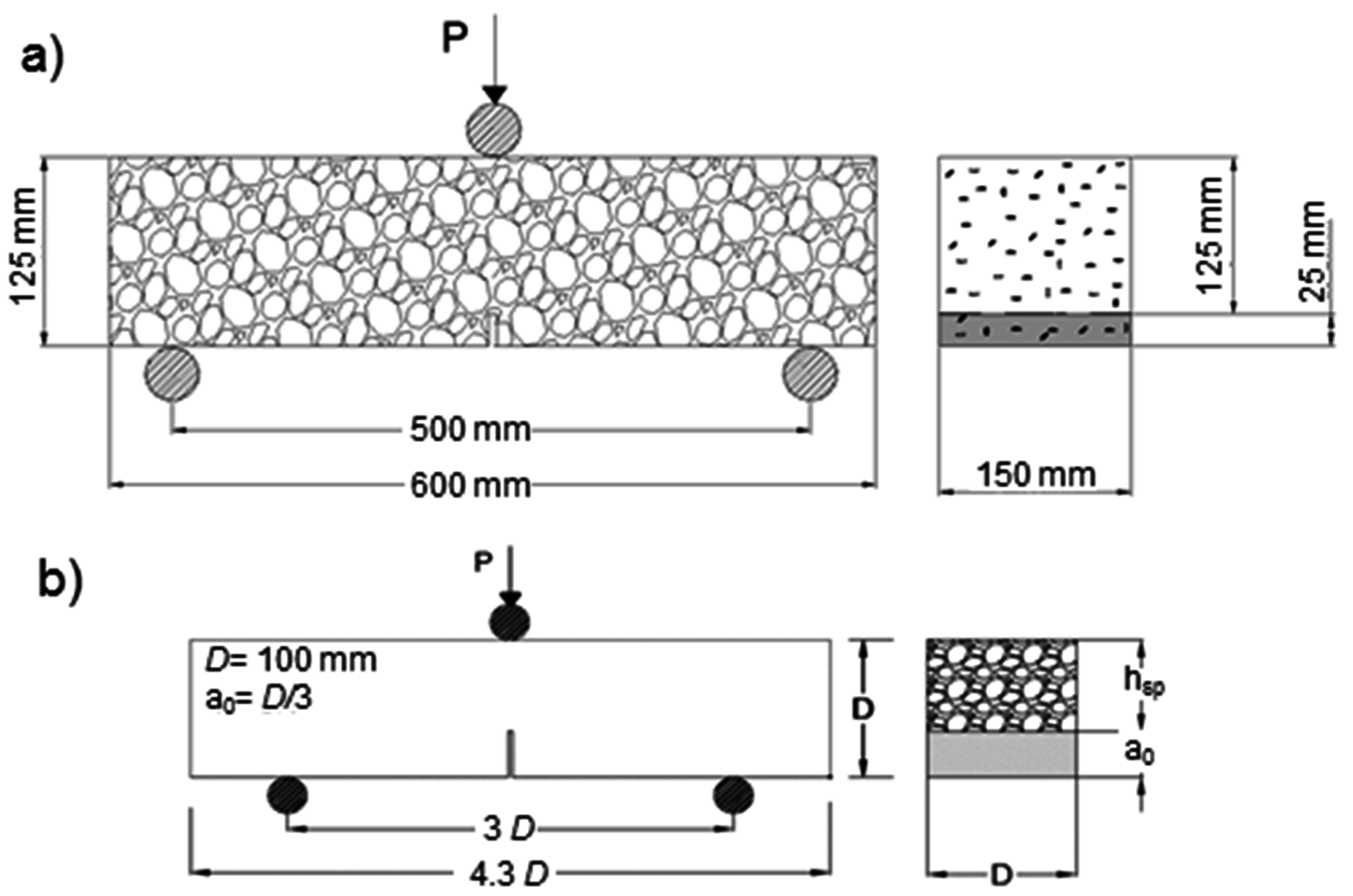
31]. The test configurations described in such standards are depicted in
Figure 9.
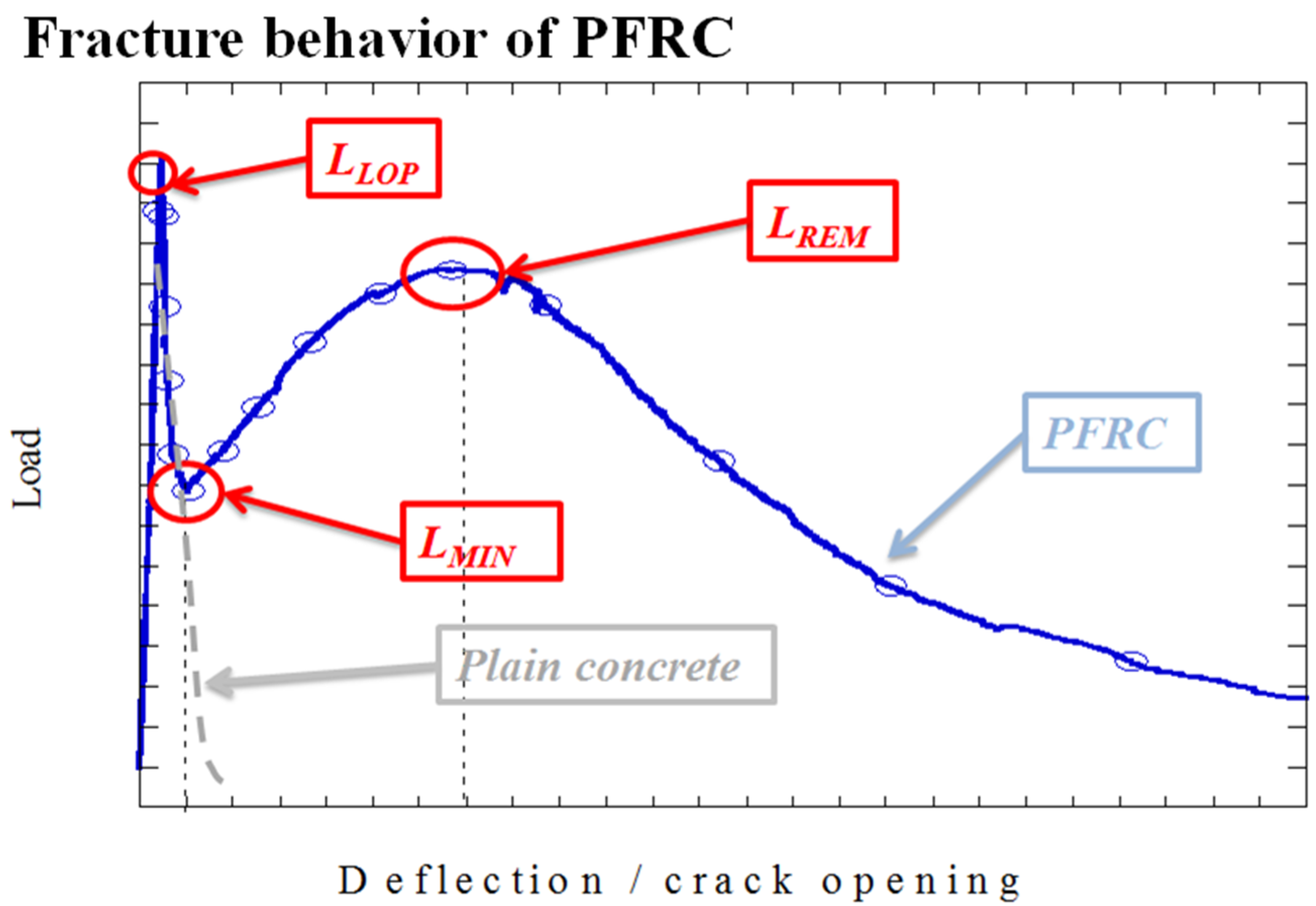
Recent research [
16,
22,
32] has shown that the PFRC provides fracture curves such as those shown in
Figure 10. That is to say, three main turning points can define the behavior: the load at the limit of proportionality (
LLOP), the minimum post-cracking load (
LMIN) and the maximum post-cracking load-bearing capacity (
LREM). There is a slight influence of the polyolefin fibers on the values of load reached in the limit of proportionality. However, in the post-cracking region, the values of load are mainly governed by the presence of fibers. The residual load values can be transformed into strength values using Equation (2), assuming the classical strength of materials formulae and, therefore, allowing the use of such strengths in the structural design as recommended in the regulations [
7,
8,
11]. In the expression,
fR,j stands for strength,
FR,j for the load,
L for the span,
b for the depth of the beam and
hsp for the ligament length (see
Figure 9).
Figure 9.
Configuration of the fracture tests: (a) EN 14651 and RILEM TC 162-TDF; (b) RILEM TC 187 SOC and ASTM C 1609/C 1690M-07.
Figure 9.
Configuration of the fracture tests: (a) EN 14651 and RILEM TC 162-TDF; (b) RILEM TC 187 SOC and ASTM C 1609/C 1690M-07.
Figure 10.
Sketch of the typical fracture curve of PFRC.
Figure 10.
Sketch of the typical fracture curve of PFRC.
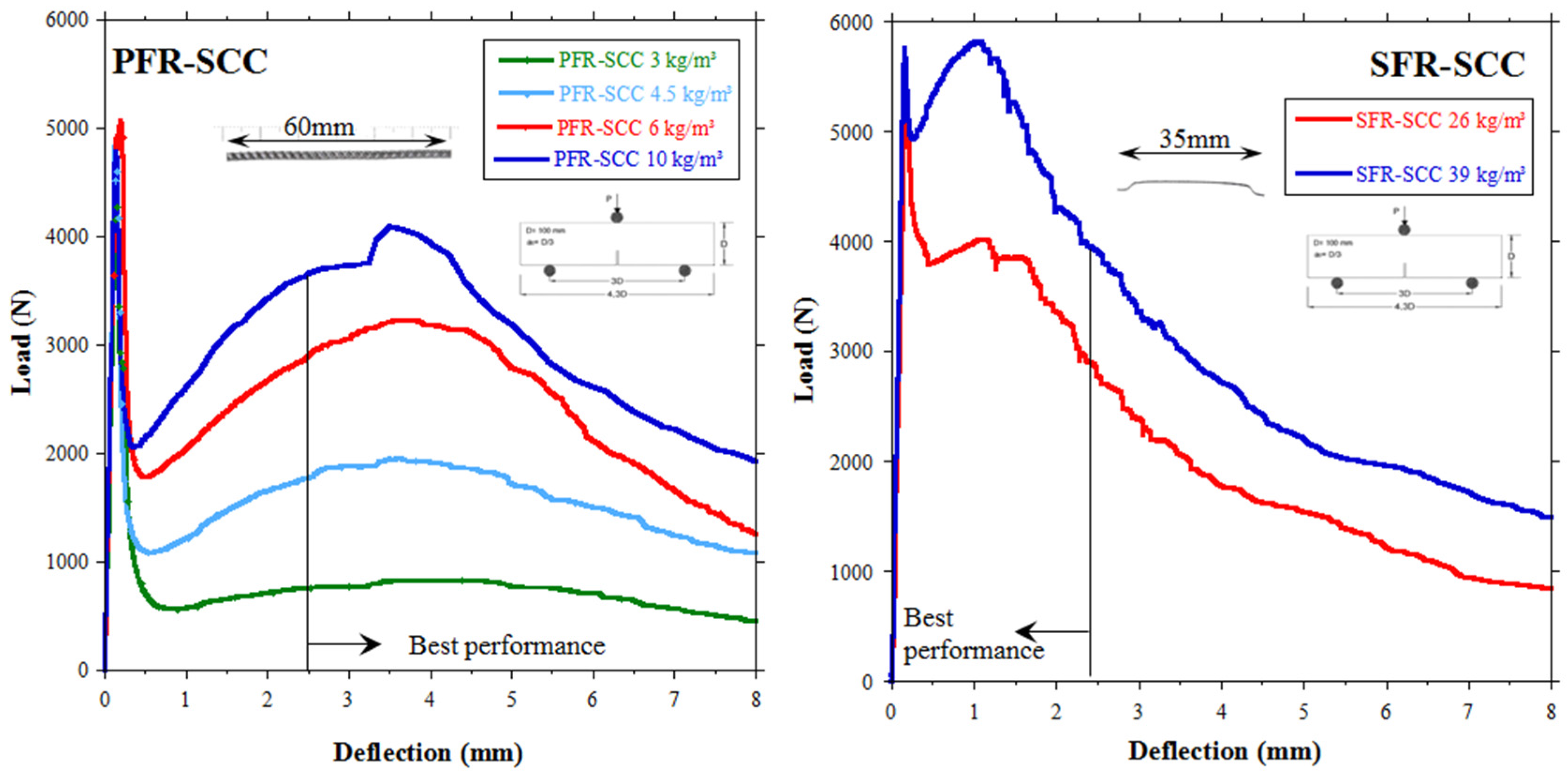
The results of Reference [
16] showed that the best performance of PFRC occurred for larger deformations than those analogues of SFRC. For the initial crack openings, steel-hooked fibers lessen the fall of strength once the limit of proportionality is surpassed.
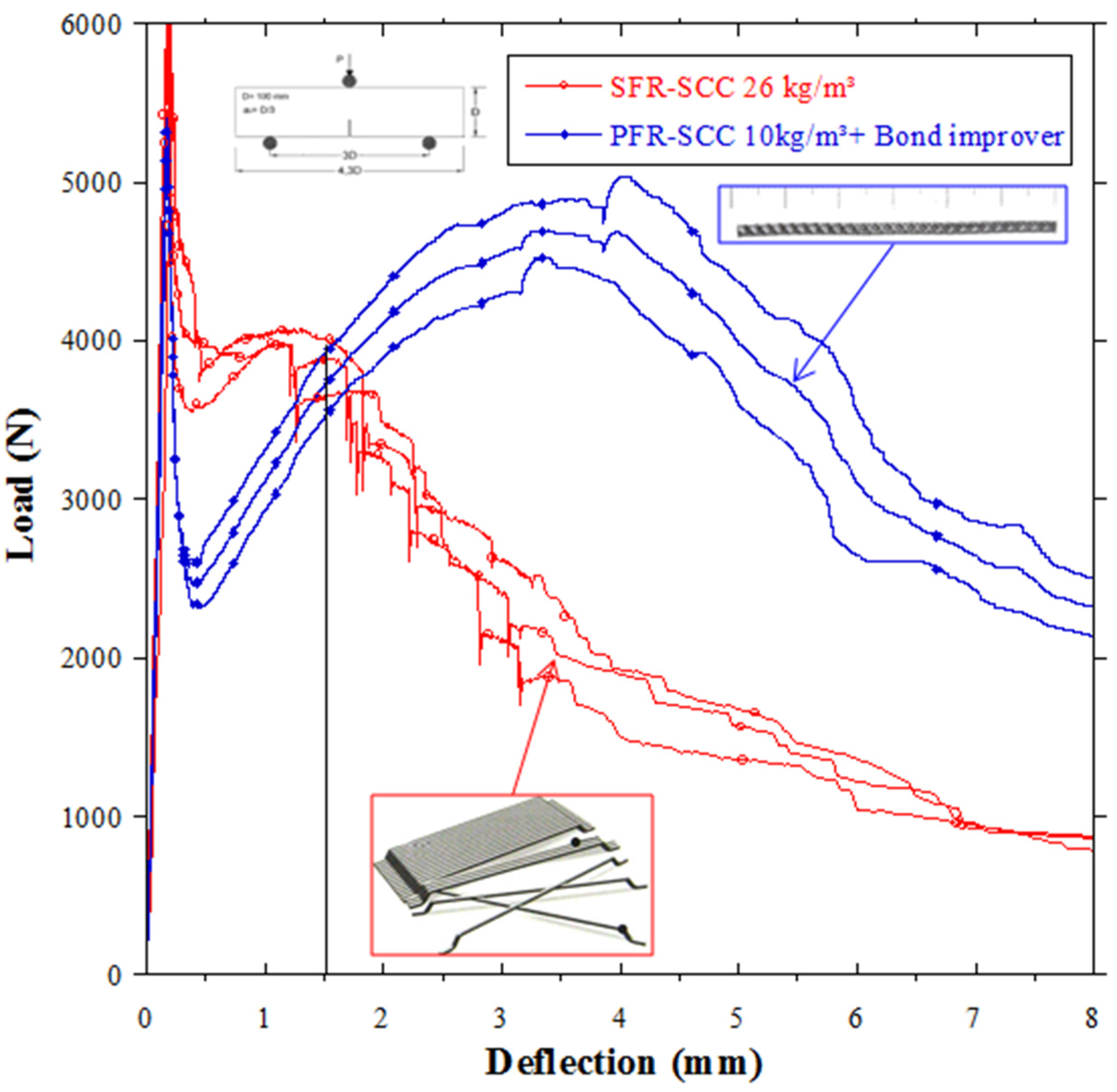
Figure 11a shows the mean results of three specimens of each type of PFRC with dosages ranging from 3 to 10 kg/m
3.
Figure 11b shows the results of SFR-SCC with, respectively, 26 and 39 kg/m
3 of steel-hooked fibers. The higher elasticity modulus and the mechanical anchorage of the hooks improve the behavior in the very first crack openings.
Figure 11.
Fracture results using the same mix proportioning of SCC: (a) PFR-SCC; (b) SFR-SCC.
Figure 11.
Fracture results using the same mix proportioning of SCC: (a) PFR-SCC; (b) SFR-SCC.
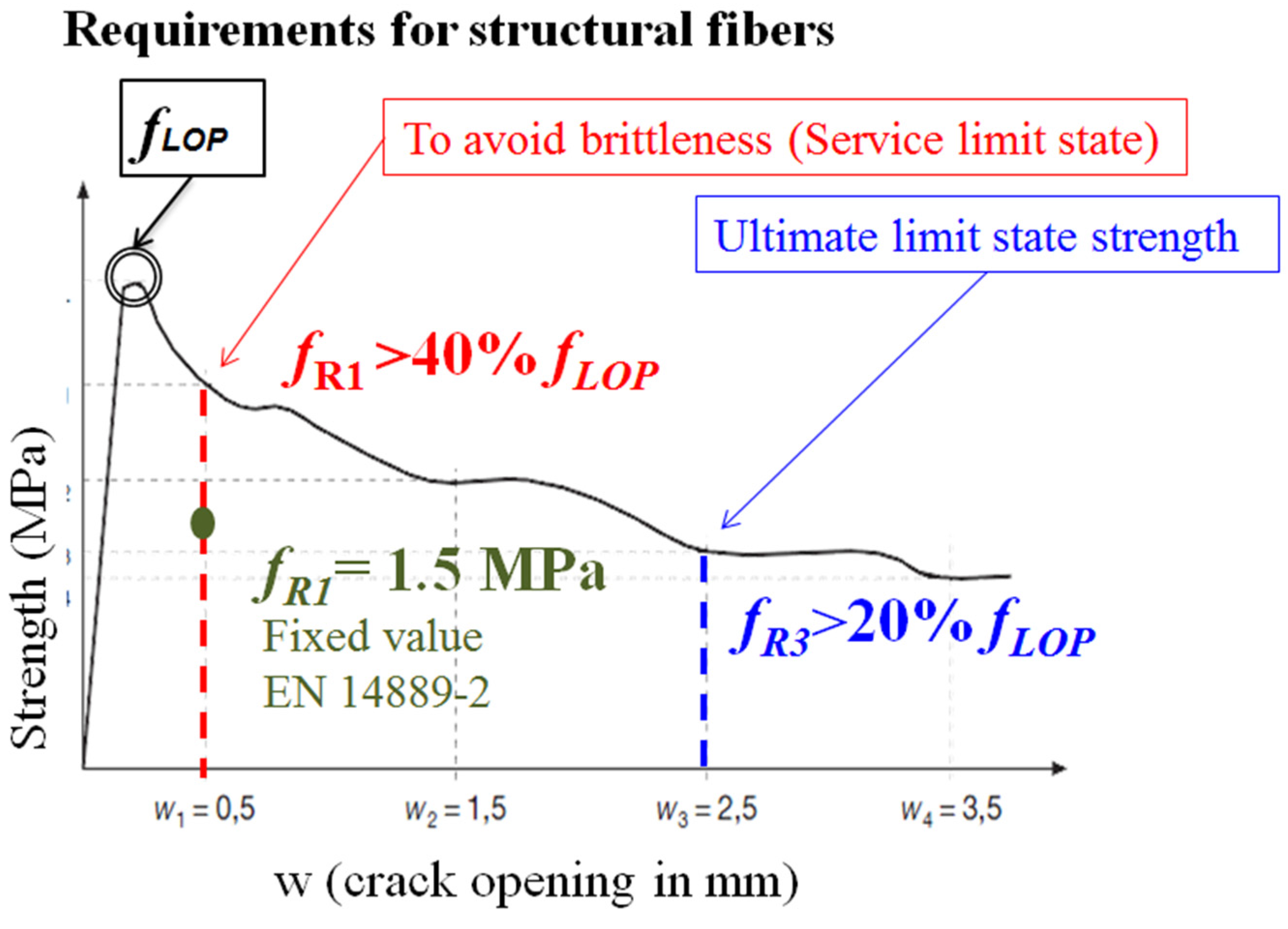
The definition of a structural fiber type slightly varies from the EN 14889 [
33] and Model Code [
7] or EHE-08 [
8]. For SLS, use of the value of strength of the FRC at a crack opening of 0.5 mm is accepted. For ULS, the value obtained at 2.5 mm of the crack opening is accepted. The values of strength at such a crack opening are commonly known, respectively, as
fR1 and
fR3 (see
Figure 12). These strengths could be assumed as the contribution of the fibers in the structural design if some additional requirements are met.
Figure 12.
Requirements of the standards to consider the contribution of the fibers in the structural design.
Figure 12.
Requirements of the standards to consider the contribution of the fibers in the structural design.
The Model Code states that fiber reinforcement can substitute (also partially) conventional reinforcement at ultimate limit state if the relationships of Equation (3) and Equation (4) are fulfilled:
These requirements in terms of a proportion of
flop contrast with the minimum fixed value of 1.5 MPa proposed by EN 14889-2 for
fR1. Establishing a proportional value permits brittleness to be avoided, although it induces a dependence on the tensile strength of concrete. These issues remain of concern for any future review of the regulations, though, at the time of writing, regulations [
7,
8] differentiate between structural and non-structural use of fibers.
The results of
fR1 and
fR3 and the strength at the crack opening 3.5 mm (
fR4) obtained as the average of two specimens of size 600 × 150 × 150 mm
3 are shown in
Table 3. Additionally, the percentage with respect to
fLOP has also been computed. By analyzing the table it can be concluded that the dosage reaching structural values in
fR1, close to 1.5 MPa, is 6 kg/m
3. The dosage of 10 kg/m
3 fully complies with the standards and shows improvements when using SCC. It should be noted that all the strengths
fR4 were higher than
fR3, showing that taking the value of
fR3 does not obtain all the possible benefits of the fibers. Moreover, it should be highlighted that all dosages of polyolefin fibers, even those in the lower threshold of the use of such plastic fibers (3 kg/m
3), exceeded the values required by the standards of being greater than 20% of
fLOP at
fR3. Besides, in order to reach
fR1 strengths higher than 40% of
fLOP, 48 mm-long fibers showed a better behavior compared with the longer fibers.
Table 3.
Residual strengths obtained from flexural tensile strength tests [
19,
22] following EN 14651 [
11].
Table 3.
Residual strengths obtained from flexural tensile strength tests [19,22] following EN 14651 [11].
| Residual Strength (MPa) (c.v.) | fLOP | fR1 | % fLOP | fR3 | % fLOP | fR4 | % fLOP |
|---|
| VCC3 | 4.81 (0.15) | 0.93 (0.30) | 19% | 0.96 (0.22) | 20% | 0.97 (0.20) | 21% |
| SCC3 | 5.21 (0.04) | 0.93 (0.01) | 18% | 1.15 (0.01) | 22% | 1.27 (0.04) | 26% |
| VCC4.5 | 4.74 (0.04) | 1.06 (0.06) | 22% | 1.40 (0.06) | 29% | 1.56 (0.06) | 33% |
| SCC4.5 | 5.23 (0.08) | 0.95 (0.07) | 18% | 1.25 (0.05) | 24% | 1.32 (0.02) | 25% |
| VCC6 | 4.41 (0.00) | 1.57 (0.03) | 36% | 2.38 (0.06) | 54% | 2.61 (0.07) | 59% |
| SCC6 | 5.09 (0.00) | 1.39 (0.09) | 27% | 2.03 (0.16) | 40% | 2.25 (0.12) | 44% |
| SCC6-48 * | 4.57 (0.24) | 1.50 (0.26) | 33% | 2.21 (0.28) | 48% | 2.24 (0.32) | 49% |
| VCC10 | 4.21 (0.14) | 1.98 (0.15) | 47% | 2.87 (0.11) | 68% | 3.05 (0.11) | 72% |
| SCC10 | 5.22 (0.05) | 2.41 (0.04) | 46% | 3.87 (0.03) | 74% | 4.16 (0.03) | 80% |
5. Designing a Combination of Steel Fibers with Polyolefin Fibers
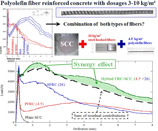
Figure 13 provides a comparison of the shapes of the PFRC and SFRC curves and justifies the combination of the two types of fibers. As can be seen in the figure, SFRC showed a scattered fall of strength typical of the rectification of the hooks, and the PFRC revealed a remarkable performance of the polyolefin fibers in advanced deformations. Since the weak point of the use of PFRC occurs for small deformations, the question appeared as a hypothesis: would it be possible to produce a FRC-SCC by using both types of fibers with a stable post-cracking response close to the value in limit of proportionality?
Figure 13.
Results using an admixture designed to improve the adherence between the polyolefin fiber and the matrix.
Figure 13.
Results using an admixture designed to improve the adherence between the polyolefin fiber and the matrix.
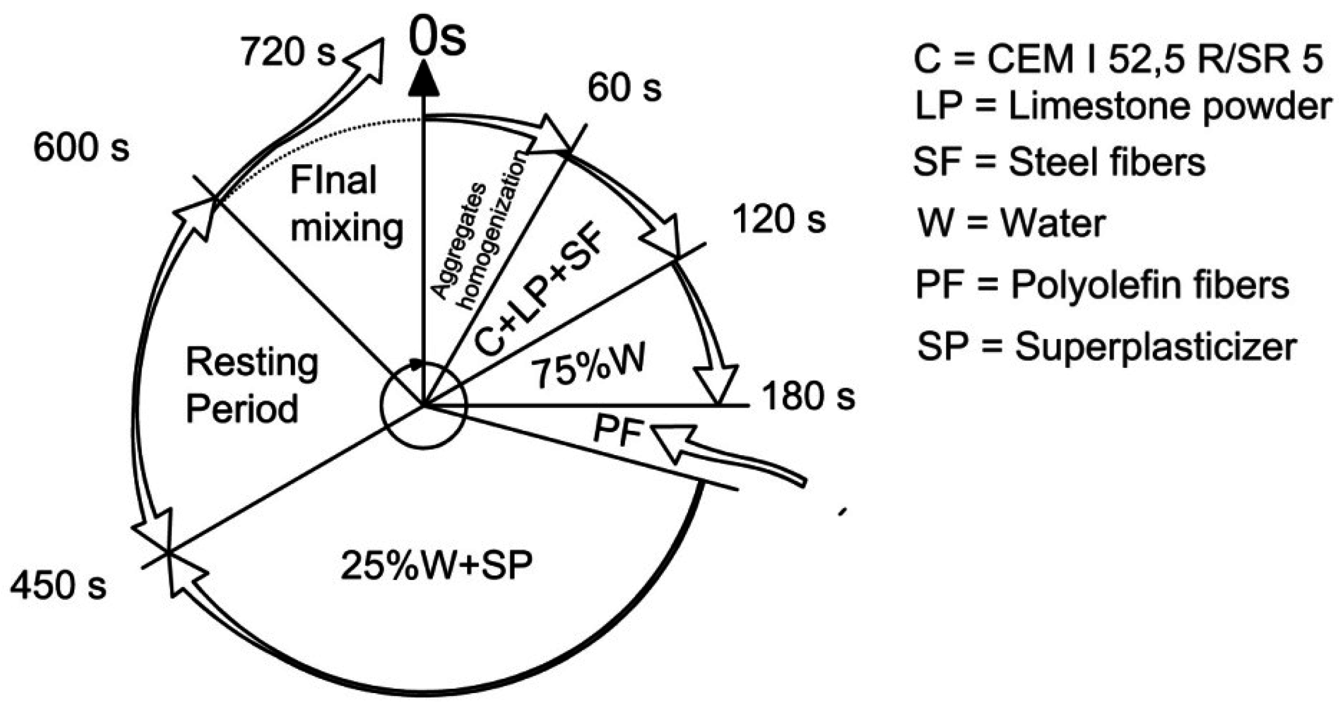
In order to respond to this, two dosages previously studied should be chosen as a reference. On the one hand, as the sum of the volume fractions was desired to be around 1%, the lower dosage of SF (0.33%) and an intermediate of PF (PFR-SCC4.5 means 0.49% in volume) seemed to be adequate. On the other, short steel-hooked fibers would allow the response for the small crack opening to be raised, which would mean that the best combination would be the 60 mm-long polyolefin fibers. Thus, the hybrid mixture named as H1 was defined, and the same specimens used for the previous types of concrete were produced in two batches. The mixing sequence was redefined as shown in
Figure 14. At this point, it is worth mentioning that 60 mm-long polyolefin fibers have 27,000 fibers per kg, while the 35 mm-long steel-hooked fibers have 14,500. If the fibers were perfectly aligned with the stress direction of the bending tests, the theoretical number of fibers (th) appearing on a fracture surface of each dosage could be shown. This has been carried out and is included in
Table 4.
Table 4 shows the results of the fresh-state and mechanical testing campaign. As can be seen, the use of the hybrid mixture did not affect the fresh state more than the steel fibers did. Furthermore, the results with a volume fraction of 0.82% showed that the mixture kept the self-compacting character. The changes in the hardened state were unnoticeable in compressive strength and elasticity modulus. However, the indirect tensile strength tests showed that the combination of fibers improved the results. It should be noted that this test is inappropriate for FRC, as second-order effects impede an apposite analysis of the results (see [
19]).
Figure 14.
Mixing sequence.
Figure 14.
Mixing sequence.
Table 4.
Fresh-state results and mechanical properties of the mixture H1.
Table 4.
Fresh-state results and mechanical properties of the mixture H1.
| State | Test | SCC | S26 | P4.5 | H1 |
|---|
| Fresh state | Slump flow test | T500 (s) | 3.5 | 3.5 | 3.5 | 4 |
| df (mm) | 655 | 570 | 600 | 565 |
| V-funnel TV (s) | 8 | 14 | 11 | 14 |
| Hardened state | Vf (%) | | 0.33 | 0.49 | 0.82 |
| th (number) | | 139 | 74 | 139 + 74 |
| Elasticity Modulus (GPa) | 35.8 | 33.7 | 31.2 | 33 |
| c.v. | 0.03 | 0.01 | 0.01 | 0.03 |
| fck, 28 days (MPa) | 39 | 41.7 | 38.5 | 36.5 |
| c.v. | 0.01 | 0.01 | 0.06 | 0.03 |
| fct indirect (MPa) | 3.8 | 5.3 | 4.2 | 5.41 |
| c.v. | 0.14 | 0.15 | 0.20 | 0.04 |
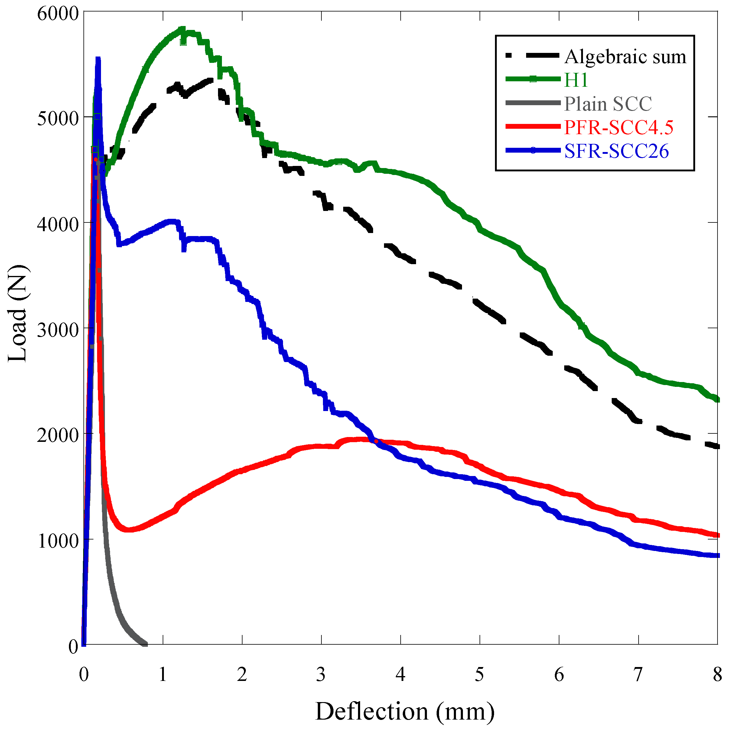
The fracture curves are shown in
Figure 15 and provide an improved analysis of the residual capacities of the hybrid mixture H1. In the figure, it can be observed that the hybrid mixture H1 obtained a higher residual load-bearing capacity than an algebraic sum of the post-cracking curves of the mono-fiber mixtures (SFR-SCC26 + PFR-SCC4.5). This showed that synergies emerged in the combined use of the two types of fibers. In addition, if
Table 5 is observed, the residual strengths were higher than 90% of
fLOP. The analysis in terms of fracture energy (see also
Table 5) obtained at a deflection of 8mm provides a 10% increase when compared with the algebraic sum of the fracture energies of SFR-SCC26 and PFR-SCC4.5.
Table 5.
Residual strengths of H1.
Table 5.
Residual strengths of H1.
| Residual Strength (MPa) (c.v.) | fLOP (MPa) | fR1 (MPa) | % | fR3 (MPa) | % | GF (N/m) |
|---|
| SCC | 5.03 (0.04) | – | – | – | – | 130 (0.05) |
| SFR-SCC26 | 6.05 (0.06) | 3.81 (0.05) | 63% | 3.45 (0.06) | 57% | 2621 (0.05) |
| PFR-SCC4.5 | 5.73 (0.01) | 1.15 (0.20) | 20% | 1.66 (0.28) | 29% | 1846 (0.42) |
| H1 | 5.48 | 4.95 (0.08) | 90% | 5.36 (0.07) | 98% | 4931 (0.12) |
Figure 15.
Fracture results of H1 and the sum of the residual contributions of mono-fiber reinforced mixtures.
Figure 15.
Fracture results of H1 and the sum of the residual contributions of mono-fiber reinforced mixtures.
The fracture surface analysis showed that the combination of the two types of fibers produced an increase in the orientation factor of both types of fibers, as can be seen in
Table 6. The description of the procedure to obtain θ and its definition can be studied in more detailed in References [
19,
32].
Table 6.
Orientation factor.
Table 6.
Orientation factor.
| Mixture | θ (Orientation factor) |
|---|
| SF | PF |
|---|
| SFR-SCC26 | 0.68 | – |
| PFR-SCC4.5 | – | 0.61 |
| H1 | 0.75 | 0.63 |


