Article

Performance of Hybrid Reinforced Concrete Beam Column Joint: A Critical Review

1
School of Engineering, University of British Columbia, Kelowna, BC V1V1V7, Canada
2
Department of Architectural Engineering, The Pennsylvania State University, University Park, PA 16802, USA
*
Author to whom correspondence should be addressed.
These authors contributed equally to this work.
Submission received: 28 November 2015 / Accepted: 28 March 2016 / Published: 12 April 2016
(This article belongs to the Special Issue Fiber Reinforced Polymers (FRP) for Infrastructure Applications)

Abstract

:
Large residual strain in reinforced concrete structures after a seismic event is a major concern for structural safety and serviceability. Alternative reinforcement materials like fiber-reinforced polymer (FRP) have been widely used to mitigate corrosion problems associated with steel. Low modulus of elasticity and brittle behavior compared to steel has made the use of FRP unsuitable in seismic resistant strictures. A combination of steel-FRP reinforcement configuration can address the problem of corrosion. Therefore, introducing a material that shows strong post elastic behavior without any decay due to corrosion is in demand. Shape memory alloy (SMA), a novel material, is highly corrosion resistive and shows super elastic property. Coupling SMA with FRP or steel in the plastic hinge region allows the structure to undergo large deformations, but regains its original shape upon unloading. In this study, the performance characteristics of four previously tested beam-column joints reinforced with different configurations (steel, SMA/steel, glass fiber reinforced polymer (GFRP) and SMA/FRP) are compared to assess their capacity to endure extreme loading. Experimental results are scrutinized to compare the behavior of these specimens in terms of load-story drift and energy dissipation capacity. SMA/FRP and SMA/Steel couples have been found to be an acceptable approach to reduce residual deformation in beam-column joints with adequate energy dissipation capacity. However, SMA/FRP is superior to SMA/Steel concerning to the corrosion issue in steel.

1. Introduction

Corrosion and formation of rust in the steel embedded in concrete generates internal stresses and causes spalling of concrete cover. It is detrimental to the performance of structural members due to the reduction in cross-sectional area as well as undermining the steel-concrete bond and may lead to catastrophic failures. Billions of dollars are spent annually on the rehabilitation of civil infrastructure, especially to address the impact of corrosion among many issues. Furthermore, modern equipment that employ magnetic interferometers, such as in hospitals and laboratory equipment require a nonmagnetic environment. These have led to an increasing interest in fiber-reinforced polymer (FRP) reinforcement, which is inherently nonmagnetic and resistant to corrosion. Additionally, the light weight of FRP offers considerable cost savings in terms of labor and requires minimum or no maintenance cost. FRP reinforcement also provides the option of easily embedding fiber optic strain measurement devices for structural health monitoring purposes. A study by Mady et al. [1] shows that glass fiber reinforced polymer (GFRP) is promising in mitigating the linear-elastic up to failure characteristics of FRP where it satisfied both strength and deformation requirements without slippage of the beam bars. Other studies [2] has shown that circular column reinforced with GFRP bars and spirals behave in a similar manner to steel RC columns in a ductile manner. Furthermore, joints in GFRP reinforced moment connections can sustain joint shear stress level up to 0.85 f c [3]. Hawileh et al. [4,5] investigated finite element modeling of structures reinforced with aramid fiber reinforced polymer (AFRP) and steel in a hybrid configuration. Modeling showed that hybrid configuration can be used to provide a balance between strength and ductility while providing superior corrosion protection.
Nonetheless, FRP materials often exhibit lower ductility and weaker bond to concrete compared to that of conventional steel reinforcement. Typically, the bond performance between FRP and surrounding concrete can be improved by means of mechanical anchorages such as surface deformations and sand coating. During strong ground motion and dynamic loading, the lower ductility of FRP still is a major concern. Brown and Bartholomew [6] showed that steel reinforced and FRP reinforced beam behave similarly in terms of section mechanics. Steel reinforced concrete strength design method is applicable to that of FRP reinforced beam to find the ultimate moment capacity. However, deflection and ductility criteria govern the design process for FRP reinforcement, which is not the case for steel reinforcement. Lower ductility of FRP remains a major concern especially in structures subjected to dynamic loading. FRP fails within its elastic range with low energy dissipation capacity, which is considered as a major drawback in seismic design [7]. Large deformations due to lower modulus of elasticity and brittle failure without prior warning may cause life safety concerns, which make use of FRP-RC elements problematic in seismic regions without additional means of energy dissipation. The use for FRP moment resisting frames in a dual system (e.g., wall-frame system) where the other component is more ductile or the use of damping devices can address such issues.
Increased ductility and energy dissipation capacity of FRP-reinforced element during seismic loading will assure structural safety, as well as mitigate the problem of corrosion. To satisfy deflection and ductility requirements, there has been a growing interest to investigate steel-free FRP and mixed steel-FRP reinforced concrete structures. To achieve ductility in a FRP-RC structural member, ductile materials, such as steel, stainless-steel, or a shape memory alloy (SMA) can be placed at the critical regions of the member, whereas FRP bars can be used in the other regions where the behavior remains linear. Regular steel is not an optimal solution due to its vulnerability to corrosion, while stainless steel can be taken into consideration. SMA is highly resistant to corrosion. SMA has shown a serious potential for use as reinforcement in concrete structures [8]. In seismic regions, SMA reinforced concrete structures can dissipate energy with no residual deformation in concrete beams [9]. Moreover, super-elastic (SE) SMA is a novel alloy with recentering feature that undergoes large deformation upon loading and regains its original shape through stress removal. If the structure is subjected to a strong earthquake, stainless steel will undergo irreversible inelastic deformation, thus, experiencing permanent deformation. Contrarily, SMA as reinforcement will not only eliminate the corrosion problem, but can also recover inelastic deformation at the end of tremors. Joints are usually the weakest links in a structure during earthquake loading. In the 1994 Northridge earthquake, failure of connections of structural members was identified as the main reason for failure of many structures [10]. SMA material can be effectively employed in beam-column joints to reduce the seismic vulnerability of reinforced concrete (RC) moment frame structures. After a seismic event, the loss of structural serviceability can further compromise safety and would be significant due to accumulated deformation if stainless steel is used. In contrast, SMA/FRP and SMA/Steel RC structural elements can sustain repeated earthquake loading despite being strained beyond its yield limit. Zafar and Andrawes [11] showed that coupled SMA-FRP composite enhanced the performance of RC moment resisting frame by reducing the inter-storey drift and increasing the energy dissipation capacity.
In this study, the performance of steel RC frame, steel-free FRP-RC, SMA/Steel and SMA/FRP-RC frame under reversed cyclic loading are compared from previously tested specimens. Scaled down beam-column joints (BCJ) of different reinforcement configurations were tested under reversed cyclic loading. The main objective of this study is to critically review the seismic behavior of a concrete BCJ reinforced with SE SMA in its plastic hinge zone and FRP or steel in its other regions, and compare its performance to that of a steel RC BCJ and steel-free FRP-RC BCJ in terms of load-drift and energy dissipation capacity. Steel RC BCJ shows superior performance amongst tested specimens, while FRP-RC BCJ offers better corrosion resistance yet is prone brittle failure. To balance both corrosion and performance criteria, SMA/FRP hybrid reinforcement configuration can be considered as an effective alternative to traditional BCJ construction.

2. Research Significance

FRP rebar is increasingly used in concrete structures due to their high corrosion resistance compared to steel. Various studies investigated FRP reinforcement behavior in beams [12,13], columns [14,15], slabs [16], and RC frames [17]. Transverse reinforcement is typically more vulnerable to corrosion since it is closer to the concrete surface. Moreover, 60% strength reduction is recommended for FRP bend, which makes FRP less appealing as stirrup [18,19,20]. FRP bar in RC structure may not provide adequate safety during seismic events due to its low ductility. Hence, to attain compression failure and provide higher safety margin in FRP-RC structures, elastic behavior under service load has to be ensured or to prevent rupture of FRP bar, over reinforcement needs to be provided [21]. In either case, the member may be overdesigned and less economic. Additionally, durability consideration of reinforcement cannot meet the seismic demand requirements. Innate high energy dissipating capacity with corrosion resistance property will serve the best solution in selecting reinforcement for RC structures. Hybrid FRP-RC structures where FRP rebar incorporated with another ductile material can be a promising solution. Meticulous experimental investigation requires sufficient understanding of the performance of hybrid FRP-RC structures in terms of ductility and energy dissipation capacity under seismic loading. The study will provide insight into the experimental investigation of BCJ with steel, steel free FRP reinforcement and will compare the outcomes with a potential hybrid technique of SMA/FRP and SMA/Steel to mitigate problems associated with steel and FRP reinforcement.

3. Scope of Previous Work

FRP NEFMAC (new fiber composite material for reinforcing concrete) grids can solve the strength reduction problems in FRP bend. Banthia et al. [22], Rahman et al. [23], Yost and Schmeckpeper [24] investigated FRP in slab as composite grid and concluded its suitability except lower punching shear strength. Alsayed et al. [25] investigated transverse GFRP reinforcement in short columns and observed a reduction in axial load capacity regardless of longitudinal rebar type. Investigation from Grira and Saatcioglu [14] shows comparable performance of CFRP and steel stirrup in column. Mirmiran et al. [26] stated that low stiffness of FRP bars cause instability failure in RC column and slenderness limits for FRP-RC columns should different than conventional columns.
Several studies investigated various hybrid steel-FRP reinforcement configurations to address the limited ductility of FRP-RC elements. Aiello and Ombres [27] tested beams of steel, FRP, and hybrid FRP-steel longitudinal bars with steel stirrups. The results showed higher ductility for hybrid reinforcement configurations but lower service deflection than FRP-RC beams. The study from Leung and Balendran [28] demonstrated that in hybrid beams, steel acts more effectively up to yielding and then the GFRP bars are engaged, thus contributing to the section resistance. Glass FRP (GFRP) was used by Said and Nehdi [7] in beam-column joints and tested under reversed cyclic loading. The study showed that while adequate joint reinforcement can maintain joint integrity, the failure in the beam is brittle. In contrast, hybrid GFRP-steel RC BCJ showed higher energy dissipation capacity and stiffness in comparison to GFRP-RC BCJ only [29]. Same observation was stated by Saikia et al. [30]. Concrete delamination at reinforcement location leads to loss of bond and anchorage failure between hybrid rebar and concrete. A half-scale three-story AFRP-reinforced concrete frame under quasi-static loading was tested by Fukuyama et al. [17]. It was argued that the rehabilitation of such a frame was easier than that of conventional RC frames since residual deformations were smaller. However, the frame was not tested to collapse and its behavior under large deformations was not reported.
Shape memory alloy, a smart material that can recover its initial shape by heating even after undergoing inelastic deformation. Variable stiffness and strength with exceptionally good corrosion resistance capacity strongly nominates SMA as reinforcement in RC structures. High cost of SMA is restraining its mass use as reinforcement in concrete. However, combining with existing reinforcing options will minimize the costs. Significant research has been done on the possible structural application of SMA [31,32,33,34,35,36,37]. SMA used in critical RC zones, where extensive yielding occurs, can yield under seismic loading and recover original shape upon release of load, thus requires minimal repair [29,32]. Ni–Ti, Cu–Zn, Cu–Zn–Al, Cu–Al–Ni, Fe–Mn, Mn–Cu, Fe–Pd, and Ti–Ni–Cu compositions of SMA have been experimented to find their properties. Ni-Ti based SMA has been accepted as the most appropriate type for structural applications [31]. Nonetheless, more economic alloys are making way for wider implementation.

4. Experimental Program

Two BCJ specimens (JBC1 and JBC4) from Nehdi et al. [33], one (JBC2) from Alam et al. [37] and one (J4) from Said and Nehdi [7] are considered in this study. These four specimens are identical in geometry and dimensions. The variations exist in configuration of reinforcing bars and applied loading. Specimen JBC1 is reinforced with regular steel bars, JBC2 has SMA rebar in plastic hinge region and regular steel bar in the remaining part of BCJ while specimen JBC4 is reinforced with SMA at the plastic hinge region of the beam along with GFRP bar in the remaining portion of the joint. The specimen J4 is made with GFRP longitudinal reinforcement and GFRP reinforcement cage as stirrups. NEFMAC type of FRP is used in J4. Individual FRP laminates are formed into rigid 2D rectangular grid shapes by layering process. GFRP bars have a rectangular cross-section, with smooth top and bottom surfaces and rough fibrous sides.
The exterior beam-column joint is isolated from an eight-story RC building with moment resisting frames at the points of contraflexure. The beam is taken to the mid-span of the bay, whereas the column is from the mid-column height of the fifth floor to the mid-column height of the sixth floor. Test specimen size is scaled downed by 3/4 and the acting force on joint was reduced by (3/4)2 to maintain similar normal stress. Reduced axial force on column of BCJ is taken 350 kN.

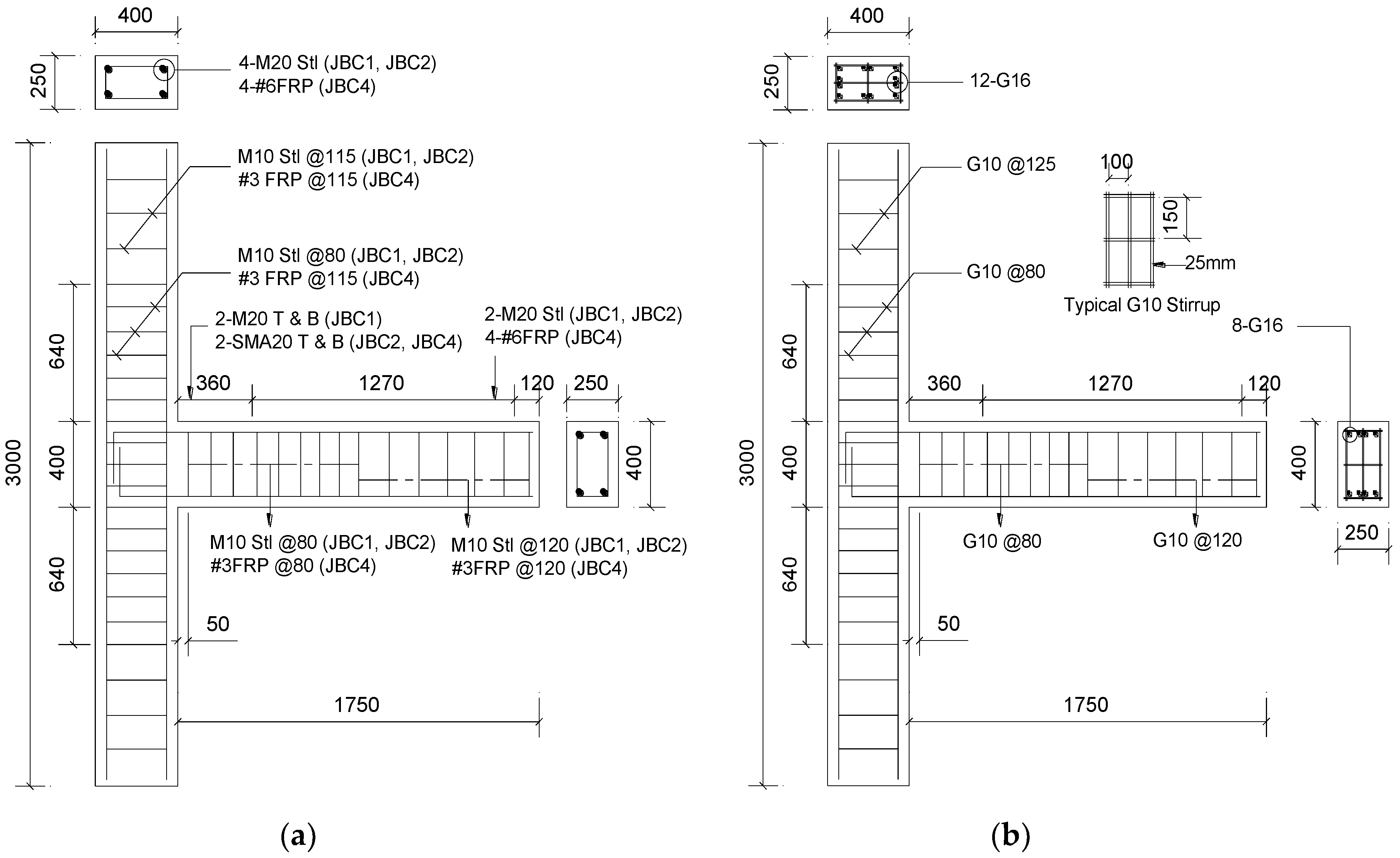
5. Materials and Specimen Details

Basic properties of materials and geometric details of each specimen are presented in Table 1. Concrete is the only common material. To make these experimental results comparable, material properties should be similar. Average concrete compressive strength is 50.95 MPa with a coefficient of variation (COV) 7.31%. Likewise, the mean tensile strength of GFRP bar in specimen JBC4 and J4 is 628 MPa. Steel reinforcement comprises the JBC1 only and SMA is integrated with steel in JBC2 and with GFRP in JBC4. Further detail on material properties can be found elsewhere [7,36,37].
The geometry, longitudinal and transverse reinforcement arrangements are similar for all four specimens. Cross section of the column is 250 mm by 400 mm with longitudinal 4-M20 (diameter: 19.5 mm) steel rebars in JBC1 and JBC2, 4-#6 (diameter: 19.1 mm) FRP rebars in JBC4 and 12-G16 GFRP bar (201 mm2 of cross-sectional area) in J4. 4-SE SMA20 (diameter: 20.6 mm) is used at the plastic hinge region of the beam in JBC2 and JBC4 as longitudinal reinforcement. The plastic hinge length is calculated as 360 mm from the face of the column [38]. The total length of 450 mm is considered for SMA bar to make provision for coupler in the joint. A new generation mechanical-adhesive type bar lock couplers with flat shear bolts is used to connect SMA bars with steel and FRP bars. Effectiveness of this mechanical coupler was previously tested by Alam et al. [39] to verify their super elastic strain.
Stirrups are spaced 80 mm in the joint region up to distance 500 mm above beam surface. For rest of the column length, the stirrup spacing is 115 mm in all specimens. Similarly, ties in the beam are spaced 80 mm for 800 mm from column face (twice the depth of beam). For JBC1 and JBC2, M10 (diameter: 11.3 mm) closed steel stirrup and for JBC4, #3 (diameter: 9.5 mm) GFRP closed rectangular ties are used as stirrup. The transverse reinforcement in specimen J4 consists of 3-branched G10 (77 mm2 of cross-sectional area) stirrups. Reinforcement details of these specimens are shown in Figure 1.

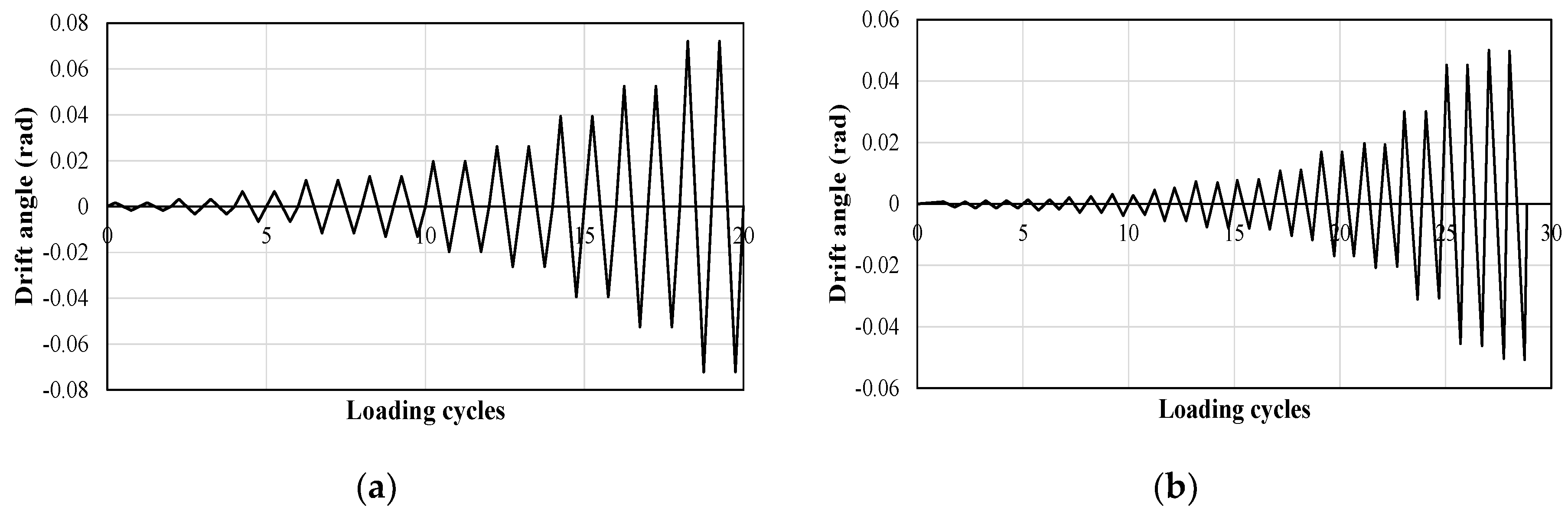
6. Test Setup and Loading

Experimental setup, load and displacement measuring techniques are well explained in the work of Nehdi et al. [36], Alam et al. [37] and Said and Nehdi [40]. Schematic illustrations of test setup and instrumentation of test specimens can be found in the original research. Load history for the reverse cyclic loadings are shown in Figure 2.
A constant axial load is applied at the top of the column and reversed cyclic load (quasi-static) applied at the beam tip. Loading applied at the beam tip was intended to induce high levels of deformations to depict the scenario of severe earthquakes. Tests were conducted up to a storey drift of at least 4%, which is more than the collapse limit (3%) defined by Kappos [41], Kircil and Polat [42].
Beam tip load in JBC specimens consists of a load-controlled phase followed by a displacement-controlled loading phase. Displacement-controlled loading is applied after yielding of longitudinal rebars. Different loading approach is selected for GFRP specimen (J4). Since, GFRP does not undergo explicit yielding, a displacement-controlled phase, similar to Fukuyama et al. [17] is applied with incremental drift. More details of loading are provided in Said and Nehdi [40] and Nehdi et al. [36].

7. Analysis of Results

Shape and geometric dimensions of these four BCJ specimens are alike (Figure 1). For parametric comparisons, the reinforcement percentage should be equal considering comparable material properties in all specimens. Table 1 shows good agreement in material properties, but the beam reinforcement percentage is higher in specimen J4 (1.61%) than the rest three specimens (1.2%). Since the other parameters and dimensions are invariable, the load and energy dissipation capacity are normalized on longitudinal reinforcement area. Results are compared up to 4% drift ratio. Though the BCJs can undergo large deformation after yielding, the inter-story drift should be within 2%–2.5% to satisfy the life safety criterion found in FEMA 273 [43]. Kappos [41], Kircil and Polat [42] defined the collapse limit as 3% inter-story drift ratio, whereas Jeong and Elnashai [44] considered 4% for collapse prevention of RC frame building. In this study, performance parameters are compared to maximum 4% story drift.

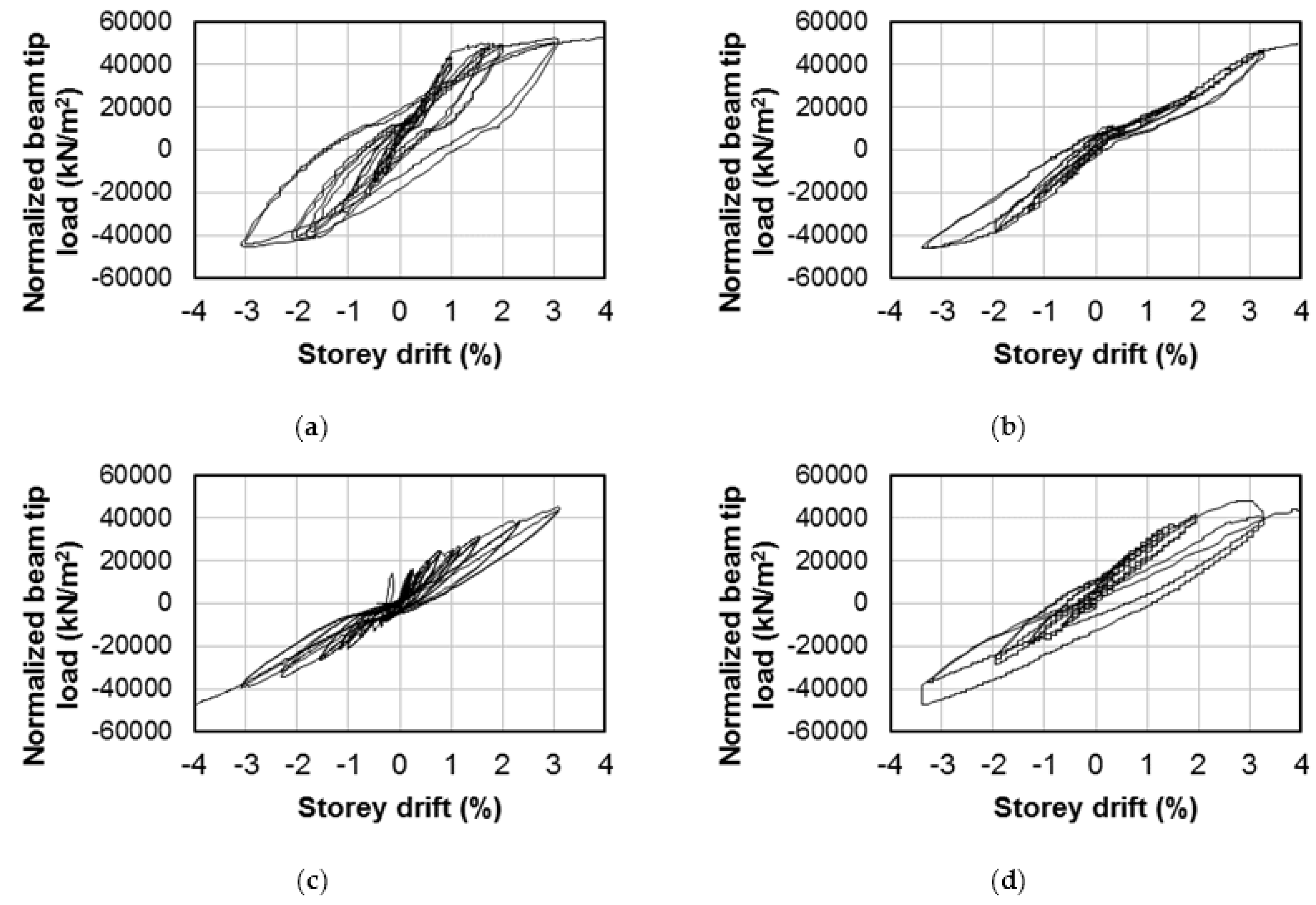
7.1. Load-Storey Drift

Figure 3 illustrates story drift relationship with the normalized beam tip load of the specimens. Figures are shown up to first occurrence of 4% story drift. The ultimate normalized beam tip load for the specimen JBC1 was 52,583 kN/m2 at a drift ratio of 4%, whereas specimen JBC2 took 49,420 kN/m2 of normalized beam tip load at the same drift ratio as JBC1. Beam reinforced with GFRP only (J4) showed 47,150 kN/m2 of normalized beam tip load for 4% drift ratio, which is almost slightly lower compared to JBC1 and JBC2. Inclusion of SMA in the plastic hinge region with GFRP at the remaining part of BCJ in specimen BCJ4 displayed normalized beam tip load of 43,333 kN/m2 (8% lower than J4) at drift ratio of 4%.
It is clear from Figure 3 that JBC1 experienced higher residual drift (1.5%) compared to that of JBC2 (0.66%) to 4% story drift. Introduction of SMA with regular steel reduced the residual drift almost 50%. SMA at the plastic hinge region allows the specimen to undergo large strain but experience negligible residual strain upon unloading, hence the specimen remains repairable and serviceable. Additionally, the SMA/FRP BCJ showed better result (1.09%) than JBC1 in terms of residual drift but higher than J4 (0.49%). This might be attributed to slippage of SMA and FRP bars inside the couplers. GFRP-RC specimen displayed lowest residual drift of all the specimens. Major problem of FRP reinforcement is it allows higher drift at lower load due to lower modulus of elasticity. However, after final unloading the beam tip of JBC2 and JBC4 could regain its original position. JBC1 encountered considerable permanent deformation and plastic set in reinforcement even after load is released.

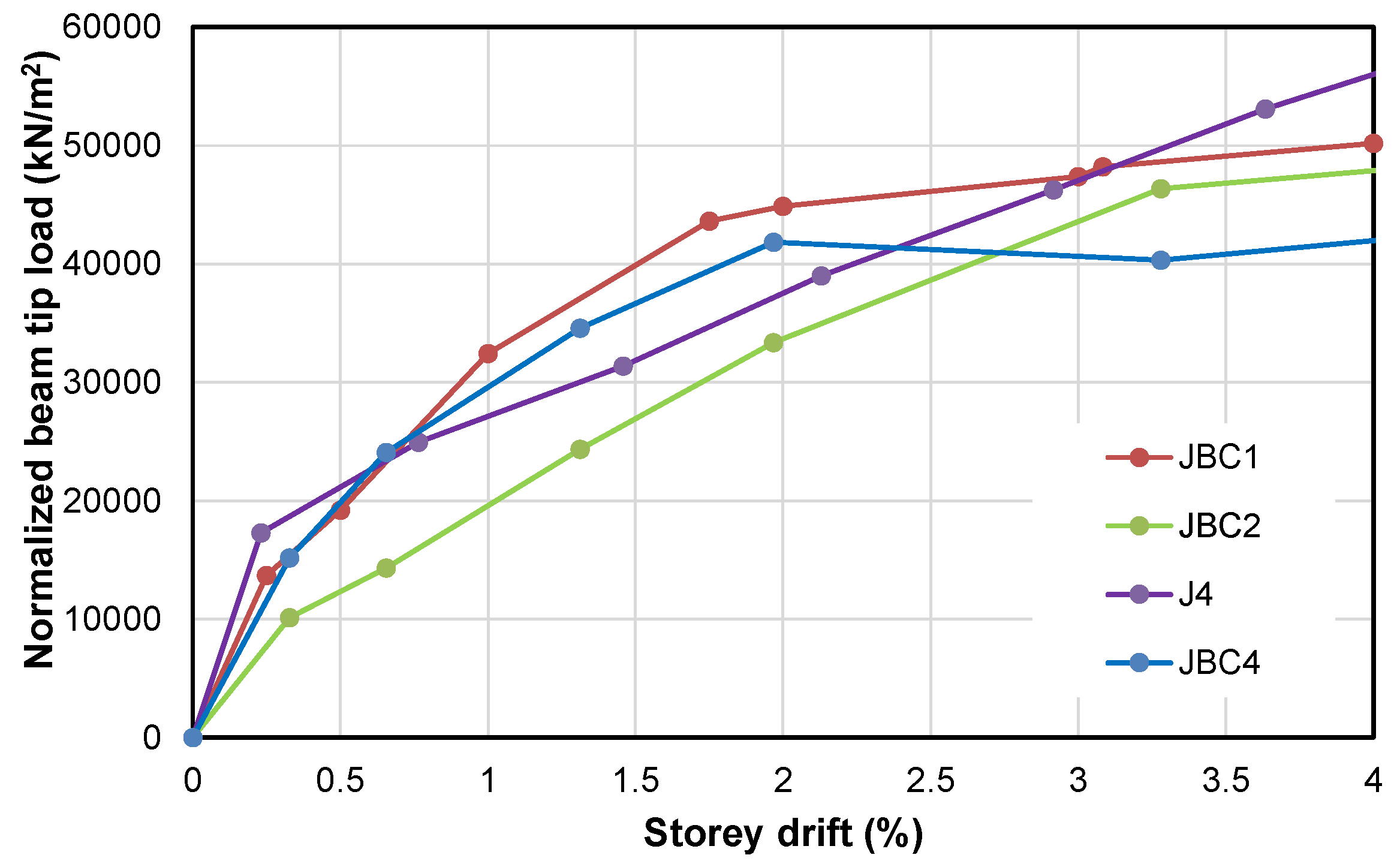
7.2. Load-Story Drift Envelope

The beam-tip load versus story drift envelope of all the specimens are shown in Figure 4. JBC1, JBC2 and JBC4 displayed elasto-plastic behavior and the GFRP-reinforced specimen (J4) had an essentially elastic envelope as represented in Figure 4. JBC1 and JBC4 started with comparable stiffness, the SMA/FRP-RC specimen experienced a drop in its stiffness after the occurrence of the first flexural crack. The SMA/Steel RC specimen started with lower stiffness and further dropped down to be plateau. This is due to SMA’s lower Young’s modulus compared to that of steel. JBC1 and J4 specimens exhibited identical load carrying capacity at a drift of about 3.0%. GFRP-RC specimen carried about 14% higher load for the same drift to SMA/FRP specimen. The scenario is different for lower drift ratio. Considering the serviceability drift of 2%, regular steel BCJ and SMA/FRP BCJ show superior results than the remaining two specimens.
For comparable percentage of reinforcement, steel RC specimen shows higher drift at the end of the test compared to that of the GFRP-RC specimen without any sudden loss of strength [7]. At 4% drift, JBC4 had 15% lower load capacity compared to that of JBC1 and JBC2, nonetheless beyond 4% drift, JBC4 could carry more than 50 kN of tip load.

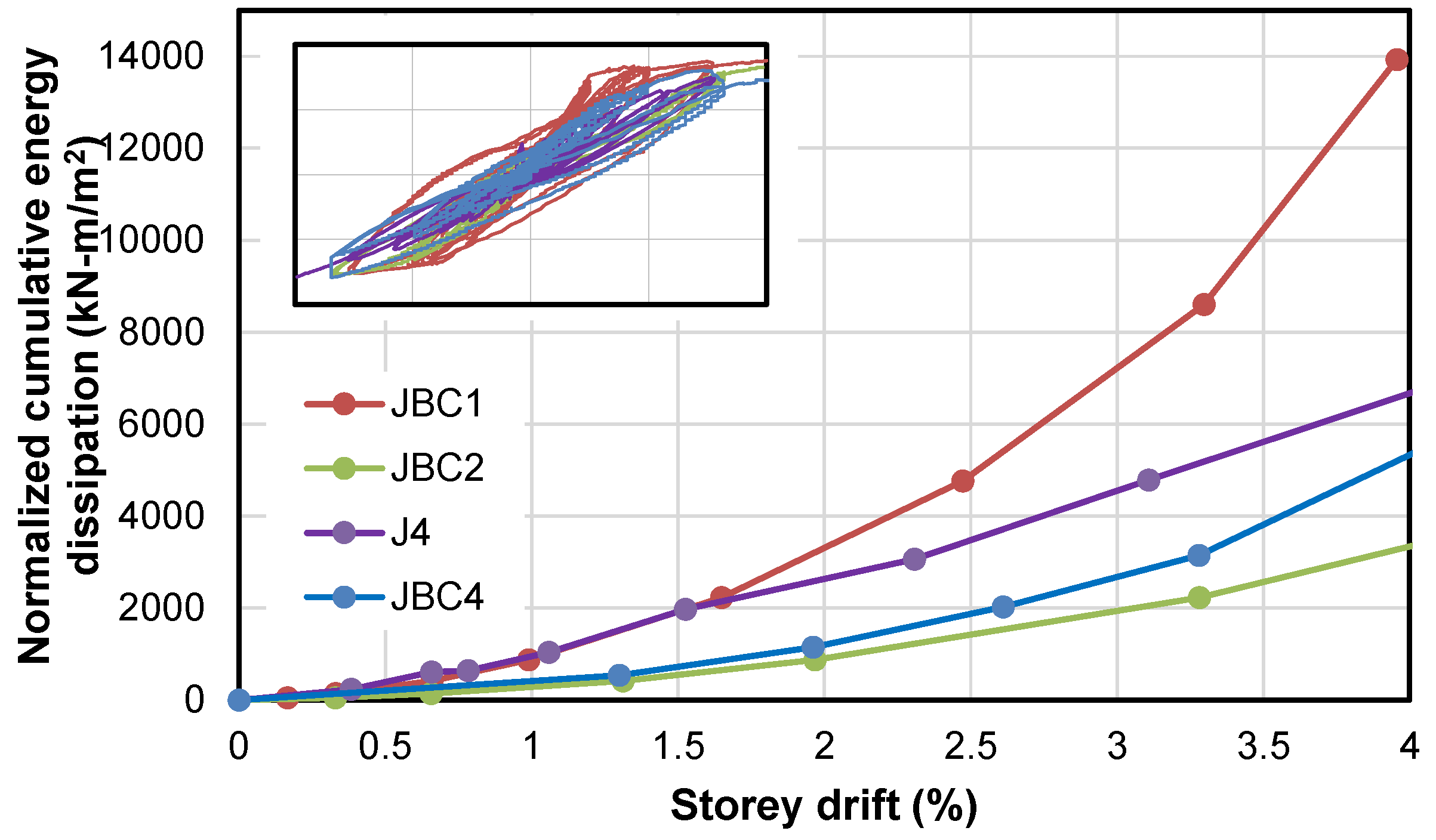
7.3. Cumulative Energy Dissipation

The energy dissipated in a cycle is calculated as the area that the hysteretic loop encloses in the corresponding beam tip load-displacement plot. Figure 5 shows plots of the cumulative energy dissipation versus story drift for the tested specimens JBC1, JBC2, J4 and JBC4. JBC1 and J4 dissipated 6865 kN-m/m2 and 4756 kN-m/m2 of normalized energy respectively at a story drift of 3%, whereas JBC2 and JBC4 dissipated 2000 kN-m/m2 and 2300 kN-m/m2 of normalized energy respectively. Though GFRP BCJ starts with similar energy dissipation capacity like steel BCJ as shown in Figure 5, it is proved that steel RC specimen dissipates significantly higher energy than FRP RC members at higher drift ratio. At a story drift of 4%, JBC4 dissipated 5300 kN-m/m2 of energy, JBC2 dissipated 3140 kN-m/m2 while JBC1 dissipated 13,930 kN-m/m2 of energy, around twofold higher than that of JBC4. At higher story drift (4%), GFRP-RC and SMA/FRP specimens displayed comparable results. JBC4 started to show gradual increase in slope at higher drift ratio, which is the scenario of devastating earthquake event. Though the steel RC BCJ dissipated energy through larger hysteric loops, SMA/FRP and SMA/Steel RC joint helped in dissipating comparable extent of energy by slippage of bars inside the concrete. Regular steel specimen has the higher ultimate energy dissipation capacity. Higher plastic deformation in steel and SMA/Steel rebar occurred in the beam, thus increased the area under each loop to enable higher energy dissipation. On the contrary, lower stiffness and inaptitude to sustain plastic deformation may cause lower energy dissipation of GFRP-RC specimen and sudden failure.

7.4. Performance Parameters

The first flexural crack (FFC) in specimen JBC1 was observed at a beam tip load of 11.7 kN corresponding to a drift of 0.22%. FFC in specimen JBC4 was at the same drift with 15.38% higher beam tip load. Specimen J4 showed FFC at a lower drift of 0.1%, almost half of specimen JBC1 and JBC2. The corresponding beam tip load was 10.5 kN, 10% lower than that of a regular steel-reinforced BCJ. Comparative test results of all the specimens are shown in Table 2. GFRP BCJ is prone to crack formation than steel or hybrid specimens. SMA/Steel specimen reflects comparable residual drift after 4% drift to specimen J4. Since GFRP has inelastic failure tendency, replacing with SMA/Steel rebar in high demand areas can possibly reduce the problem. Even though SMA/FRP BCJ showed higher residual drift due slippage inside coupler, proper interlocking between SMA-FRP should have led to lower residual strain in BCJ. In this case, SMA/FRP is best option to avert corrosion issues in BCJ while maintaining adequate levels of capacity and ductility.

8. Conclusions

An insight into the performance of novel hybrid structural configurations for beam column joint subassemblages is presented in the paper for potential development of new structural solutions that are corrosion-free ductile RC structures. Scrutinizing and analyzing the experimental test results, the following conclusions can be drawn.
  • The GFRP reinforced BCJ showed similar energy dissipation to SMA/FRP BCJ specimen at higher drift, but GFRP exhibits very low plasticity features under reversed cyclic loading. Up to collapse limit of drift 3%, J4 showed satisfactory result. However, in extreme loading events the performance of JBC1, JBC2 and JBC4 is expected to be superior to J4.
  • Specimen JBC4 dissipated comparable amount of energy to that of JBC2. Nevertheless, the energy dissipation was governed by significant slippage of FRP, steel and SMA bars. Larger hysteretic loops of steel in JBC1 resulted in higher energy dissipation compared to SMA reinforced specimens. Proper coupling between SMA-FRP and SMA-steel would guarantee higher energy dissipation capacity due to the super elastic property of SMA.
  • Specimen JBC2 outperformed JBC1 in terms of residual drift after unloading. JBC4 failed to do so due to bar slippage inside couplers inside RC specimen. Although the steel RC BCJ dissipated a relatively higher amount of energy compared to that of JBC2, JBC2 performed better due to its post-elastic strain recovery capability. This makes SMA an attractive option to replace regular steel especially in plastic hinge region where even after high seismic activity, the BCJ can dissipate significant amount of energy without large residual deformation.
  • SMA/FRP BCJ specimen displayed a force-displacement hysteresis similar to that of the steel RC BCJ with reduced stiffness and comparable residual drift. Inclusion of SE SMA at the plastic hinge region was supposed to reduce residual drift significantly which hindered due to significant slippage of the FRP bar inside the couplers. However, JBC4 could still carry load beyond the collapse limit. Such corrosion free SMA/FRP-RC structural elements can be used in highly corrosive environments with minimum or no maintenance.
  • FRP specimen is likely to show crack at lower load and drift ratio than steel or SMA incorporated specimens. This impedes the aesthetics of structure and acts as the root of subsequent damages.
Excessive residual displacement increases the probability of failure during subsequent earthquakes and makes the structure non-repairable. New construction after demolition costs a great deal of money. To avoid life-threatening damage and keep the RC structure serviceable even after seismic events, SMA reinforcement can be used in the plastic hinge region of RC elements. Hybrid structure like SMS/steel shows an excellent performance regarding residual drift, but coupling SMA with FRP boosts the corrosion resistance ability to the reinforcement in RC members marking the energy dissipation capacity.

Author Contributions

All authors contributed extensively to the study presented in this paper. Original experimental investigations were done by M. Shahria Alam and Aly M. Said. The study was jointly conceived by the authors to prepare a critical review over the experimental outcomes. Md Rashedul Kabir assembled the data, analysed and prepared the manuscript under the super vision of M. Shahria Alam and Aly M. Said. Achraf Ayad added supplementary information and edited the manuscript. All authors discussed the results, reviews and agreed to the modifications at all stages.

Conflicts of Interest

The authors declare no conflict of interest.

References

  1. Mady, M.; El-Ragaby, A.; El-Salakawy, E. Seismic behavior of beam-column joints reinforced with GFRP bars and stirrups. J. Compos. Constr. 2011, 15, 875–886. [Google Scholar] [CrossRef]
  2. Afifi, M.Z.; Hamdy, M.M.; Benmokrane, B. Axial capacity of circular concrete columns reinforced with GFRP bars and spirals. J. Compos. Constr. 2013, 18, 040130171. [Google Scholar] [CrossRef]
  3. Hasaballa, M.; El-Salakawy, E. Shear capacity of exterior beam-column joints reinforced with GFRP bars and stirrups. J. Compos. Constr. 2015, 20, 04015047. [Google Scholar] [CrossRef]
  4. Hawileh, R.A. Finite element modeling of reinforced concrete beams with a hybrid combination of steel and aramid reinforcement. Mater. Des. 2015, 65, 831–839. [Google Scholar] [CrossRef]
  5. Hawileh, R.; Abdalla, J.A.; Naser, M.Z.; Tanarslan, M. Finite element modeling of shear deficient RC beams strengthened with NSM CFRP rods under cyclic loading. Spec. Publ. 2015, 301, 1–18. [Google Scholar]
  6. Brown, V.L.; Bartholomew, C.L. FRP reinforcing bars in reinforced concrete members. ACI Mater. J. 1993, 90, 34–39. [Google Scholar]
  7. Said, A.; Nehdi, M. Use of FRP for RC frame in seismic zones: Part II. Performance of steel free GFRP-reinforced beam–column joints. Appl. Compos. Mater. 2004, 11, 227–245. [Google Scholar] [CrossRef]
  8. Tazarv, M.; Saiidi, M.S. Reinforcing NiTi superelastic SMA for concrete structures. J. Struct. Eng. ASCE 2014, 141, 04014197. [Google Scholar] [CrossRef]
  9. Abdulridha, A.; Palermo, D.; Foo, S.; Vecchio, F.J. Behavior and modeling of superelastic shape memory alloy reinforced concrete beams. Eng. Struct. 2013, 49, 893–904. [Google Scholar] [CrossRef]
  10. Mahin, S.A. Lessons from damage to steel buildings during the Northridge earthquake. Eng. Struct. 1998, 20, 261–270. [Google Scholar] [CrossRef]
  11. Zafar, A.; Andrawes, B. Incremental dynamic analysis of concrete moment resisting frames reinforced with shape memory composite bars. Smart Mat. St. 2012, 21, 025013. [Google Scholar] [CrossRef]
  12. Toutanji, H.A.; Saafi, M. Flexural behavior of concrete beams reinforced with glass fibre-reinforced polymer (GFRP) bars. ACI Struct. J. 2000, 97, 712–719. [Google Scholar]
  13. Salib, S.R.; Sayed, A.G. Prediction of crack width for fibre-reinforced polymer-reinforced concrete beams. ACI Struct. J. 2004, 101, 532–536. [Google Scholar]
  14. Grira, M.; Saatcioglu, M. Reinforced concrete columns confined with steel or FRP Grids. In Proceedings of the 8th Canadian Conference on Earthquake Engineering, Vancouver, BC, Canada, 13–18 June 1999; pp. 445–450.
  15. Choo, C.C. Investigation of Rectangular Concrete Columns Reinforced or Prestressed with Fibre Reinforced Polymer (FRP) Bars or Tendons. Ph.D. Dissertation, University of Kentucky, Lexington, KY, USA, 2005. [Google Scholar]
  16. Udhayakumar, V.; Bharatkumar, B.H.; Balasubramanian, K.; Krishnamoorthy, T.S.; Lakshmanan, N. Experimental investigations on flexural behaviour of RC slabs reinforced with GFRP rebars. J. Inst. Eng. (India) Civil. Eng. Div. 2007, 88, 23–27. [Google Scholar]
  17. Fukuyama, H.; Masuda, Y.; Sonobe, Y.; Tanigaki, M. Structural Performances of Concrete Frame Reinforced with FRP Reinforcement. In Proceedings of the Second International RILEM Symposium on Non-Metallic (FRP) Reinforcement for Concrete Structures, Ghent, Belgium, 23–25 August 1995; pp. 275–286.
  18. Rizkalla, S.; Mufti, A. Reinforcing Concrete Structures with Fibre Reinforced Polymers. In ISIS Canada Manual No. 3; University of Manitoba: Winnipeg, MB, Canada, 2001. [Google Scholar]
  19. El Chabib, H.; Nehdi, M.; Said, A. Evaluation of shear capacity of FRP reinforced concrete beams using artificial neural networks. Smart Struct. Syst. 2006, 2, 81–100. [Google Scholar]
  20. El Chabib, H.; Nehdi, M.; Said, A. Proposed shear design equations for FRP-reinforced concrete beams based on genetic algorithms approach. ASCE J. Mater. Civil. Eng. 2007, 19, 1033–1042. [Google Scholar]
  21. Sharbatdar, M.K.; Saatcioglu, M. Seismic design of FRP reinforced concrete structures. Asian J. Appl. Sci. 2009, 2, 211–222. [Google Scholar] [CrossRef]
  22. Banthia, N.; Al-Asaly, M.; Ma, S. Behavior of concrete slabs reinforced with fiber-reinforced plastic grid. J. Mater. Civil. Eng. 1995, 7, 252–257. [Google Scholar] [CrossRef]
  23. Rahman, A.H.; Kingsley, C.Y.; Kobayashi, K. Service and ultimate load behavior of bridge deck reinforced with carbon FRP grid. J. Compos. Constr. 2000, 4, 16–23. [Google Scholar] [CrossRef]
  24. Yost, J.R.; Schmeckpeper, E.R. Strength and serviceability of FRP grid reinforced bridge decks. J. Bridg. Eng. 2001, 6, 605–612. [Google Scholar] [CrossRef]
  25. Alsayed, S.H.; Al-Salloum, Y.A.; Almusallam, T.H.; Amjad, M.A. Concrete columns reinforced by GFRP rods. In Fourth International Symposium on Fiber-Reinforced Polymer Reinforcement for Reinforced Concrete Structures, SP-188; Dolan, C.W., Rizkalla, S.H., Nanni, A., Eds.; American Concrete Institute: Baltimore, MD, USA, November 1999; pp. 103–112. [Google Scholar]
  26. Mirmiran, A.; Yuan, W.; Chen, X. Design for slenderness in concrete columns internally reinforced with fiber-reinforced polymer bars. ACI Struct. J. 2001, 98, 116–125. [Google Scholar]
  27. Aiello, M.A.; Ombres, L. Structural performances of concrete beams with hybrid (fibre-reinforced polymer-steel) reinforcements. J. Compos. Constr. 2002, 6, 133–140. [Google Scholar] [CrossRef]
  28. Leung, H.Y.; Balendran, R.V. Flexural behaviour of concrete beams internally reinforced with GFRP rods and steel rebars. Struct. Surv. 2003, 21, 146–157. [Google Scholar] [CrossRef]
  29. Nehdi, M.; Said, A. Behaviour of hybrid (Steel-GFRP) reinforced concrete frames under reversed cyclic loading. Mater. Struct. 2005, 38, 627–637. [Google Scholar] [CrossRef]
  30. Saikia, B.; Thomas, J.; Ramaswamy, A.; Rao, K.S.N. Performance of hybrid rebars as longitudinal reinforcement in normal strength concrete. Mater. Struct. 2005, 38, 857–864. [Google Scholar] [CrossRef]
  31. Alam, M.S.; Nehdi, M.; Youssef, M.A. Applications of Shape Memory Alloys in Earthquake Engineering. In Proceedings of the 9th Canadian Conference on Earthquake Engineering, Ontario, Canada, 26–29 June 2007.
  32. Alam, M.S.; Youssef, M.A.; Nehdi, M. Seismic Behaviour of Concrete Beam–Column Joints Reinforced with Superelastic Shape Memory Alloys. In Proceedings of the 9th Canadian Conference on Earthquake Engineering, Ontario, Canada, 26–29 June 2007.
  33. Alam, M.S.; Youssef, M.A.; Nehdi, M. Utilizing shape memory alloys to enhance the performance and safety of civil infrastructure: A review. Can. J. Civil. Eng. 2007, 34, 1075–1086. [Google Scholar] [CrossRef]
  34. Alam, M.S.; Nehdi, M.; Youssef, M.A. Shape memory alloy based smart RC bridge: overview of state of the art. Smart Struct. Syst. 2008, 4, 367–389. [Google Scholar] [CrossRef]
  35. Saiidi, M.S.; Wang, H. Exploratory study of seismic response of concrete columns with shape memory alloys reinforcement. ACI Struct. J. 2006, 103, 435–442. [Google Scholar]
  36. Nehdi, M.L.; Alam, M.S.; Youssef, M.A. Development of corrosion-free concrete beam-column joint with adequate seismic energy dissipation. Eng. Struct. 2010, 32, 2518–2528. [Google Scholar] [CrossRef]
  37. Alam, M.S.; Youssef, M.A.; Nehdi, M.L. Analytical prediction of the seismic behaviour of superelastic shape memory alloy reinforced concrete elements. Eng. Struct. 2008, 30, 3399–3411. [Google Scholar] [CrossRef]
  38. Paulay, T.; Priestley, M.N.J. Seismic Design of Reinforced Concrete and Masonry Buildings; John Wiley & Sons Inc.: New York, NY, USA, 1992. [Google Scholar]
  39. Alam, M.S.; Youssef, M.A.; Nehdi, M. Exploratory investigation on mechanical anchors for connecting SMA bars to steel or FRP bars. Mater. Struct. 2010, 43, 91–107. [Google Scholar] [CrossRef]
  40. Said, A.; Nehdi, M. Rehabilitation of RC frame joints using local steel bracing. Struct. Infrastruct. E. 2008, 4, 431–447. [Google Scholar] [CrossRef]
  41. Kappos, A.J. A comparative assessment of R/C structures designed to the 1995 Eurocode 8 and the 1985 CEB seismic code. Struct. Des. Tall Build. 1997, 6, 59–83. [Google Scholar] [CrossRef]
  42. Kircil, M.S.; Polat, Z. Fragility analysis of mid-rise R/C frame buildings. Eng. Struct. 2006, 28, 1335–1345. [Google Scholar] [CrossRef]
  43. Applied Technology Council (ATC). NEHRP Guidelines for Seismic Rehabilitation of Buildings. In Rep. No. FEMA 273, Prepared for the Building Seismic Safety Council (BSSC) by the ATC; Federal Emergency Management Agency: Washington, DC, USA, 1997. [Google Scholar]
  44. Jeong, S.H.; Elnashai, A.S. Probabilistic fragility analysis parameterized by fundamental response quantities. Eng. Struct. 2007, 29, 1238–1251. [Google Scholar] [CrossRef]
Figure 1. Reinforcement details of specimens (all dimensions in mm) (a) JBC1, JBC4 (adapted from [36]) & JBC2 (adapted from [37]) (b) J4 (adapted from [7]).
Fibers 04 00013 g001
Figure 2. Reverse cyclic load used for (a) JBC1, JBC4 and JBC2 (adapted from [36,37]) (b) J4 (adapted from [7]).
Fibers 04 00013 g002
Figure 3. Beam tip load–storey drift relationship of specimen (a) JBC1 (b) JBC2 (c) J4 (d) JBC4.
Fibers 04 00013 g003
Figure 4. Beam tip load versus story drift envelope of the tested specimens.
Fibers 04 00013 g004
Figure 5. Cumulative energy dissipation-story drifts relationship of specimens.
Fibers 04 00013 g005
Table 1. Material properties and geometric details of specimens.
GeometrySpecimen
JBC1JBC2JBC4J4
Beam:
Dimension (mm)250 × 400250 × 400250 × 400250 × 400
Longitudinal reinforcement (T&B: Top and Bottom)4-M20 (ϕ19.5 mm)4-M20 (ϕ19.5 mm)4-#6FRP (ϕ19.1 mm)8-G16 (201 mm2)
Longitudinal reinforcement at plastic hinge region (T&B)4-M20 (ϕ19.5 mm)4-SMA20 (ϕ20.6 mm)4-SMA20 (ϕ20.6 mm)8-G16 (201 mm2)
Transverse reinforcementM10@ 80–120 mmM10@ 80–120 mm#3FRP@ 80–120 mmG10@ 80–120 mm
Column:
Dimension (mm)250 × 400250 × 400250 × 400250 × 400
Longitudinal reinforcement4-M204-M204-#6FRP12-G16
Transverse reinforcementM10@ 80–115 mmM10@ 80–115 mm#3FRP@ 115 mmG10@ 80–125 mm
Material
Concrete:
Compressive strength (MPa)53.553.745.750.9
Split cylinder tensile strength (MPa)3.52.83.0
Steel: (longitudinal)
Yield strength (MPa)520450
Ultimate strength (MPa)630650
Young’s modulus (GPa)198193
Steel: (transverse)
Yield strength (MPa)422422
Ultimate strength (MPa)682682
GFRP:
Tensile strength (MPa)656600
Tensile modulus (GPa)47.630
SMA:
Young’s modulus (GPa)62.562.5
Yield stress at phase transformation (MPa)401401
Maximum stress up to SE strain (MPa)510510
First stage of unloading stress (MPa)370370
Second stage of unloading stress (MPa)130130
SE plateau strain (%)6.006.00
Table 2. Comparative test results of specimens.
Performance Parameter/SpecimenJBC1JBC2JBC4J4
First flexural Crack Load (kN)11.713.510.5
Drift at first flexural crack (%)0.220.220.1
First diagonal crack (kN)30.042
Drift at first diagonal crack (%)0.660.1
Yield load (kN)51.334.1
Displacement at yield load (mm)1218
Drift at yield load (%)1.301.97
Load at 3% drift (kN)60.053.957.573.9
Load at 4% drift (kN)61.059.552.089.4
Residual drift after 4% drift (%)1.80.762.00.48
Energy dissipation after 3% story drift (kN-m)3.42.43.16.21

