Influence of Steel and Macro-Synthetic Fibers on Concrete Properties


1
Department of Civil, Environmental, Architectural Engineering and Mathematics, University of Brescia, 25123 Brescia, Italy
2
Civil Engineering and Engineering Mechanics Department, Columbia University, New York, NY 10027, USA
*
Author to whom correspondence should be addressed.
Fibers 2018, 6(3), 47; https://0-doi-org.brum.beds.ac.uk/10.3390/fib6030047
Submission received: 5 June 2018
/
Revised: 25 June 2018
/
Accepted: 29 June 2018
/
Published: 11 July 2018
(This article belongs to the Special Issue Recent Advancements in Fiber Reinforced Concrete And its Applications)
Abstract
:Fiber addition has become one of the most prevalent methods for enhancing the tensile behavior of concrete. Fibers reduce cracking phenomena and improve the energy absorption capacity of the structure. On the other hand, the introduction of fibers can introduce a negative impact on concrete workability, whose loss is influenced by different parameters (among which are fiber content and fiber type). In this context, an exploratory study on the influence of steel (high stiffness) and macro-synthetic (low stiffness) fibers on the fresh properties of concrete was carried out, considering workability and air content, as well as resultant mechanical performance. Four fiber types at two volume fractions (0.5% and 1.0%) were studied in two base concretes with different water-to-cement ratios (0.45 and 0.50) by using the slump test, DIN flow table test and air content meter. An additional parameter for the DIN flow table test is proposed herein to quantify the potential preferential flow direction caused by fiber orientation and entanglement. Air meter results showed that the fibers caused only a slight increase in concrete air content; this agreed well with the results of mechanical testing, which showed no apparent effect on measured compressive strength. In addition, it was captured that, for a given fiber volume fraction, steel fibers more adversely affected Fiber Reinforced Concrete (FRC) workability as compared to polypropylene ones, while the opposite result was obtained considering FRC toughness.
1. Introduction
Fibers are effective for partially or totally replacing conventional reinforcement in non-structural and structural elements such as industrial floor, road pavements, beams (shear reinforcement) [1,2,3,4,5,6], slabs [7] and tunnel linings [8]. The use of fibers in these elements is allowed by design guidelines available in several countries [9,10,11,12] but, more importantly, Fiber Reinforced Concrete (FRC) was recently included in the fib Model Code 2010 [13,14]. Fibers of varying materials and shapes are available. Steel fibers are the most commonly used [1,7,8], and macro-synthetic fibers have significantly improved in the past decade and are now able to impart significant toughness to concrete [15,16]. Furthermore, in relation to the contribution of cement-based materials to sustainability, the use of fibers is commonly combined with the use of clinker alternatives [17,18,19], such as fly ash [20,21] and silica fume [22], as well as in combination with crystalline admixtures for improving self-healing capacity [23,24].
Although there are several benefits from using fibers in concrete, it is well known that any type of fiber will reduce the workability, i.e., compactability, mobility and stability [25,26,27]. Due to their relatively high specific surface area, fibers increase water demand and thereby can affect concrete mixing, placing and compacting. In addition, there can be challenges in dispersion, where fibers entangle and result in non-uniform distribution in the concrete matrix. Consequently, an FRC that cannot be placed and compacted easily will affect constructability and will not lead to the required strength or durability characteristics of the material and, consequently, of the overall structure [28]. This aspect underscores the importance of carefully evaluating the fresh properties of FRC related to workability. Workability is influenced by different factors, among which are water content, cement content, aggregate characteristics, admixtures, fiber type and content.
In comparison to the numerous studies present in the literature about the hardened properties of FRC, only a relatively small number of studies are focused on its workability [25,29,30,31,32,33,34,35,36,37,38]. In addition, most of these studies are focused on steel fibers [25,29,30,31,32,33,34,35,36,37,38], while macro-synthetic fibers were studied only in [34]. In these investigations, different test methods were adopted to measure the fresh properties related to workability, including slump [25,29,30,31,32,33,34,37,38], Vebe test [25,29,30,33,36,37,38], inverted cone test [29,33,34,36], compacting factor test [36], DIN flow table test [34,35] and rheometers [34,36]. All these tests were mainly developed for Plain Concrete (hereafter PC). The slump test is the most common method for both PC and FRC, even if it only provides a measure of concrete consistency. Slump test cannot provide a good index of workability in terms of placeability and compactability of FRC under vibration [27]. For vibrated FRC, the Vebe test is more suitable. However, the slump test is still the most used method on the building site, while Vebe test is more popular in the laboratory. In addition, the Vebe test is applicable only to low workability and stiff concretes, which are in general to be avoided for construction since sufficient concrete mobility and pumpability are generally required. Concerning the other tests, the compacting factor test [39] measures the degree of compaction for a standard amount of work, while the inverted cone [40] and DIN flow table [41,42] tests allow for measuring concrete flowability. It is worth mentioning that the DIN flow table test, which was developed for PC by Graf in 1933 [41], is commonly used in Germany for evaluating the workability of concrete on-site. Finally, rheometers are rarely used to characterize the rheological parameters for concretes but instead more for normal and high strength mortars with fiber addition [43,44,45].
Another important fresh property that may be affected by the presence of fibers is the air content, which can influence the workability, strength and durability of concrete. However, very few studies are present in the literature and there is still disagreement within the research community on the possible influence of fibers on concrete air content. For instance, Bayasi et al. [33] found that fibers increase the concrete air content, whose percentage depends on fiber type and shape. Similar results were also found by Page et al. [46] studying flax fibers in concrete. On the other hand, Balaguru et al. [31] stated that the addition of fibers reduces the air content of concrete and that the rate of loss of air is slightly higher for FRC. In addition, in the ACI Report 544.1R-96 [9] the potential influence of synthetic fibers on concrete air content is highlighted.
The aim of the present manuscript is to shed some new light on the fresh properties of FRC mixes, as well as the resultant hardened properties (i.e., compressive strength and residual post-cracking behavior under flexure). Two steel (high stiffness) and two macro-synthetic (low stiffness) fibers with similar aspect ratios were adopted in two base concretes varying in both water-to-cement ratio (0.45 and 0.50) and fiber volume fraction (0%, 0.5%, 1.0%) to evaluate the influence of steel and macro-synthetic fibers on fresh concrete properties.
2. Experimental Program
2.1. Material Properties
The effect of fibers on the concrete properties was studied on two different base concretes:
- C50 with a mean cylindrical compressive strength of about 50 MPa and water-to-cement ratio (w/c) of 0.45;
- C45 with a mean cylindrical compressive strength of about 45 MPa and w/c ratio of 0.50.
Table 1 shows the mix design of these two base concretes. Sand (specific weight of 2640 kg/m3, absorption coefficient of 0.20% and fineness modulus of 2.75), coarse crushed aggregates angular in shape (specific gravity of 2680 kg/m3, absorption coefficient of 0.94% and fineness modulus of 7.70), Portland Type I cement and tap water were used in all mixes. Both base concretes incorporated polycarboxylate-based superplasticizer (SP), where the dosage was adjusted to provide a target slump of 180 mm ± 20 mm, corresponding to a S4 slump class, and a target flow of 500 mm ± 10 mm, corresponding to a F4 flow class. As expected, a higher dosage was needed for C50 given its lower water content.
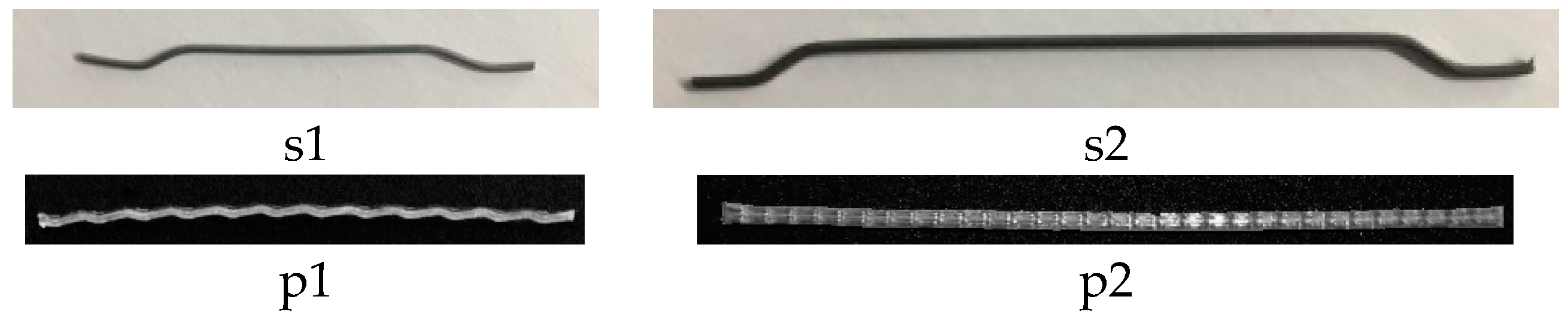
- Two steel fibers having a hooked end shape: short fibers 35 mm long (s1) and long fibers 60 mm long (s2);
- Two macro-synthetic fibers: crimped polypropylene fibers 40 mm long (p1) and embossed polypropylene fibers 54 mm long (p2).
It is worth mentioning that, although the fibers exhibited varying length, shape and stiffness, they all had a similar aspect ratio of approximately 60. Fibers were added to concrete in two different volume fractions (Vf): 0.5% and 1.0%. To better capture the influence of fiber type, it should be noted that aside from fiber type and amount, all the other mix variables were kept constant. This was possible since relatively small fiber volume fractions (≤1%) were used. A similar approach was also carried out in [32,33,34,36,37], where for a given FRC (as a function of fiber type and amount), a specific mix could be designed to emphasize fiber performance and limit workability losses [26,47].
Table 3 reports the eighteen different concrete matrices that were investigated. There were nine mixes for each base concrete (C45 and C50), namely one plain concrete (PC), four Steel Fiber Reinforced Concrete (SFRC) and four Polypropylene Fiber Reinforced Concrete (PFRC). All the necessary information is included in the concrete designations, e.g., designation C50-p1-0.50% refers to a base concrete C50 reinforced by p1 fibers at a volume fraction of 0.50%.
2.2. Test Methods
All mixes were prepared by using a laboratory rotary concrete mixer. The mixing protocol consisted of the following steps:
- Dry-mix the sand, coarse aggregate and fibers for 90 s;
- Addition of cement. Mix for 90 s;
- 90 s of rest;
- Addition of liquid (water + superplasticizer listed in Table 1) in the mixer to have “base concrete + fibers”; mix for 5 min. The mixture is then ready for evaluating workability and air content.
- Addition of supplementary superplasticizer to obtain PC consistency (slump of 180 ± 20 mm); mix for 2 min.
- The mixture is then ready for casting.
For each concrete, the following steps were followed:
- Measure the air content, consistency (slump test) and flowability (DIN flow table test) on “base concrete + fibers”.
- Adjust polycarboxylate-based superplasticizer to obtain the target slump of 180 ± 20 mm, then repeat slump test, DIN flow table test and air content measurement.
- Cast beams and cylinders.
- Test compressive and residual flexural tensile strength at 28 days.
FRC fresh properties were measured three times for each matrix. Therefore, the values reported in Section 3 are the average of at least three measurements.
A type B air meter was used to measure concrete air content, following the pressure method specified in ASTM C231 [48]. Concrete workability was measured by both the slump [49,50] and DIN flow table tests [42].
In accordance to the standards, 150 mm × 150 mm × 500 mm beams and Ø = 150 mm—h = 300 mm cylinders were produced. Three beams and six cylinders were cast for each mix. The curing procedure [51] was as follows: initial curing by covering the molded samples with a non-absorptive sheet, removal from molds 24 h after casting, then storage in a moist environment at 20 °C ± 2 °C until testing.
3. Experimental Results and Discussion
3.1. Fresh State Properties of PC and FRC
Table 4 shows the mean fresh properties (coefficient of variation (CV) provided in brackets) of all tested mixes, i.e., air content, slump and flow.
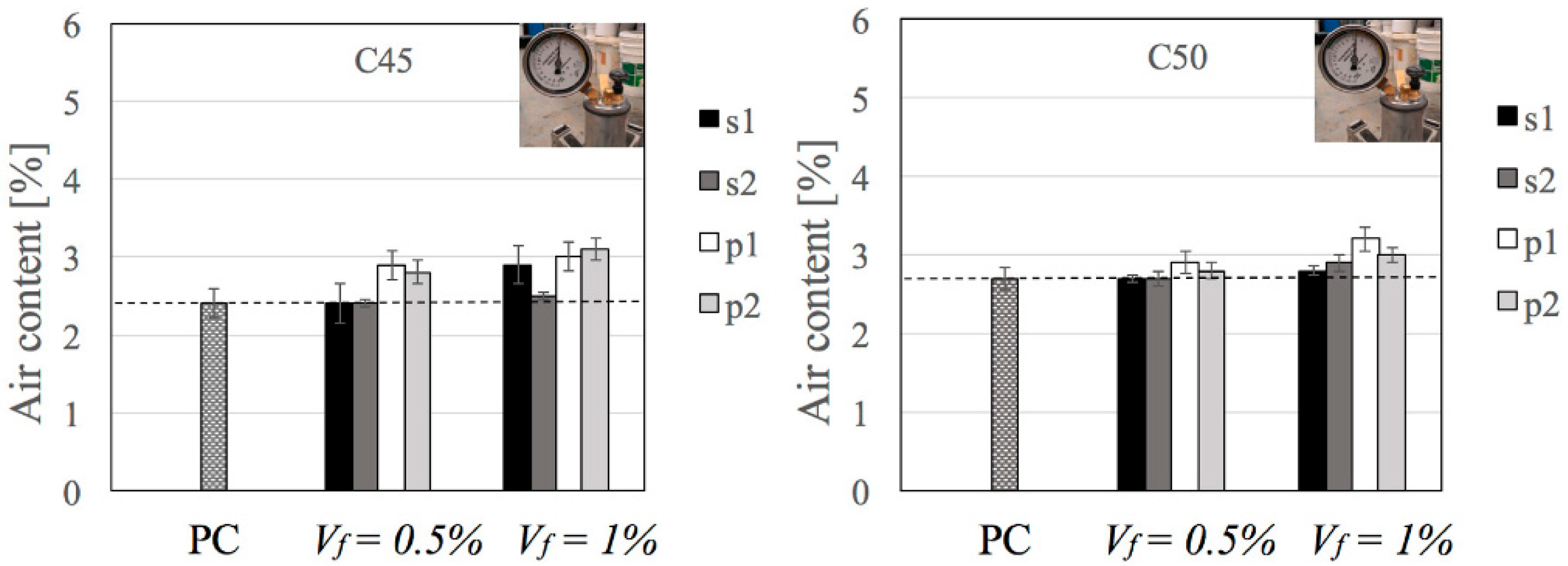
3.1.1. Influence of Fibers on Air Content
Figure 2 summarizes the effect of fiber amount and type on air content. It can be observed that all results are characterized by a low CV (varying between 0.02 and 0.09), indicating good repeatability of the measurements overall. Both steel and macro-synthetic fibers led to a slight increase in air content and its variability, as well as an increase in air content with Vf. However, results show that macro-synthetic fibers more adversely affected air content than steel fibers in both C45 and C50. Up to Vf = 1%, for both fiber types the increase in air content was marginal, indicating that fiber influence was negligible in the concrete investigated. This has positive implications as in the majority of structural and non-structural applications of fibers, the adopted values of Vf are generally not greater than 1%. Still, it would be interesting in future studies to investigate the effect of fibers on air content for Vf values greater than 1% or in different base concrete systems for more specialized applications.
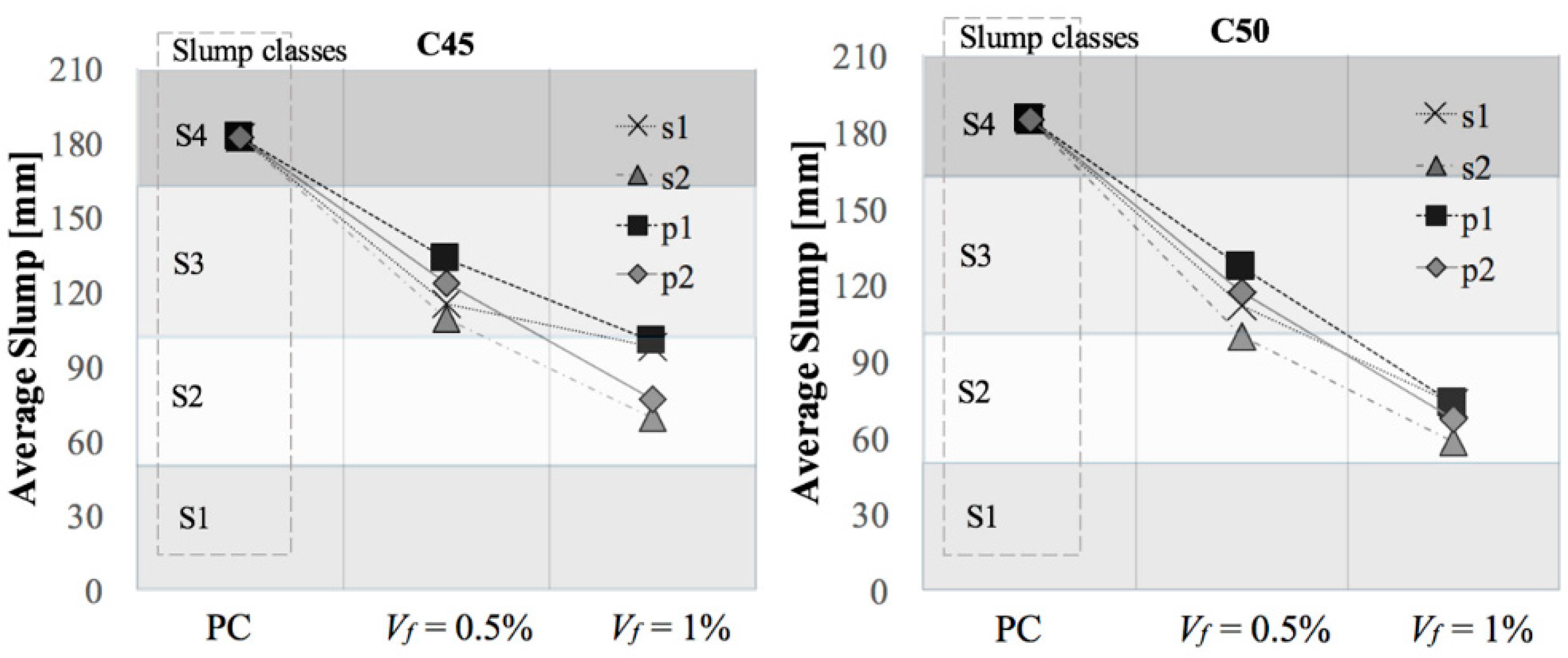
3.1.2. Influence of Fibers on Slump
Regarding concrete consistency, Figure 3 shows slump reduction as a function of fiber type and content (slump classes S1, S2, S3 and S4 according to EN 206-1 [54] are also underlined in Figure 3). It is worth mentioning that all the slump values obtained were within the acceptable range of the test (see Section 2.2).
As expected, a noticeable slump reduction due to fiber addition was observed in both C45 and C50, indicating stiffer, less workable mixes. As shown in Figure 3, the reduction was nearly linear for all fibers and was more pronounced in C50 than in C45. A similar trend was observed by other researchers studying different concretes and fiber types [33,38]. In addition, considering the CV values listed in Table 4, it can be observed that the addition of fibers not only reduced slump, but also increased the scatter. In fact, increase in Vf resulted in an increase in the slump scatter and the scatter worsened at lower w/c ratios—the CV reached a max of 0.19 for Vf = 1% within C45 and 0.28 for Vf = 1% within C50. This indicates that, at a given w/c ratio, the reliability of the slump test is reduced for FRC compared to PC, likely due to greater heterogeneity of the material. By comparing steel versus polypropylene fibers, it is apparent in Figure 3 that polypropylene fibers led to a smaller reduction in consistency of about 15% as compared to steel fibers in both base concretes. At Vf = 0.5%, steel fibers reduced the slump by 40% while macro-synthetic fibers did so by 30%. Similarly, at Vf = 1%, steel fibers and macro-synthetic fibers reduced slump by about 60% and 55%, respectively. It should also be noted that for both fiber types, the long fibers (s2 and p2) were characterized by a higher reduction in consistency of about 15–20% as compared to the short fibers (s1 and p1).
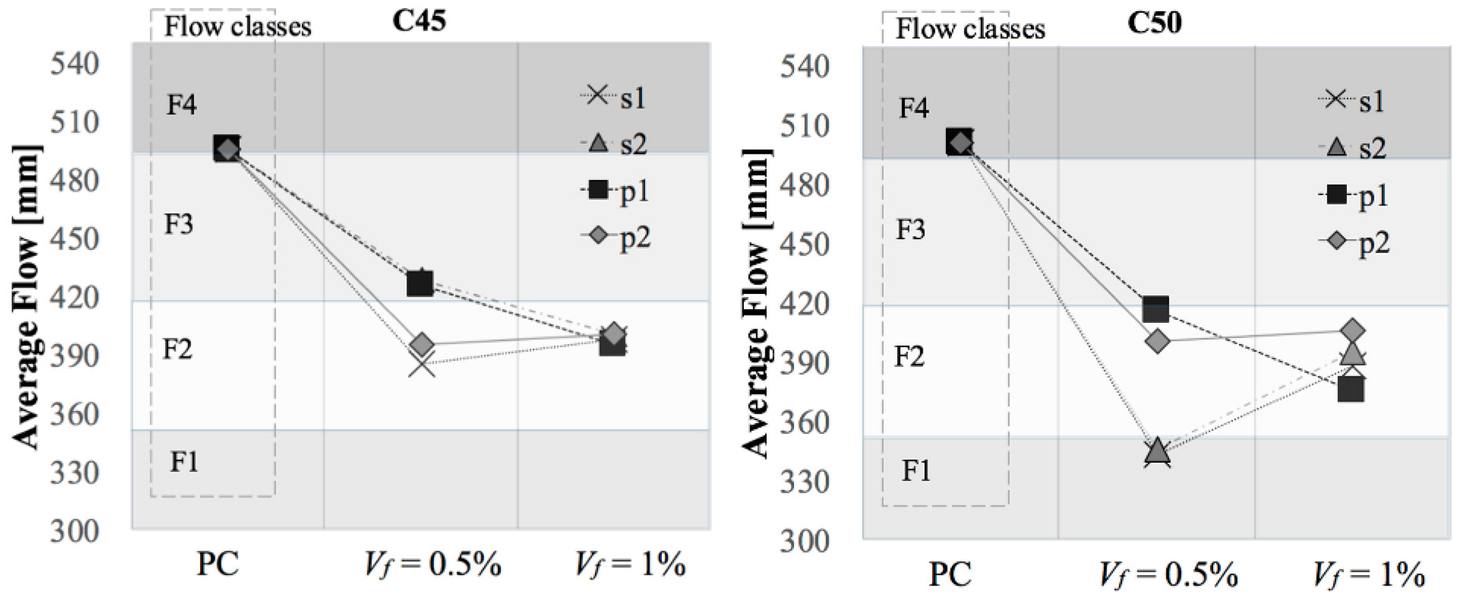
3.1.3. Influence of Fibers on Concrete Flow
Figure 4 shows the DIN flow table test results in terms of average flow vs. fiber content for concrete C45 and C50 (flow classes F1, F2, F3 and F4 according to EN 206-1 [54] are also underlined in Figure 4). It can be observed that both steel and macro-synthetic fibers significantly reduced concrete flowability (by up to 35%) and increased average flow variability compared to the base concretes (Table 4). It should be also noted that the CV values for the DIN flow table test (Table 4) are generally smaller than those observed in the slump test.
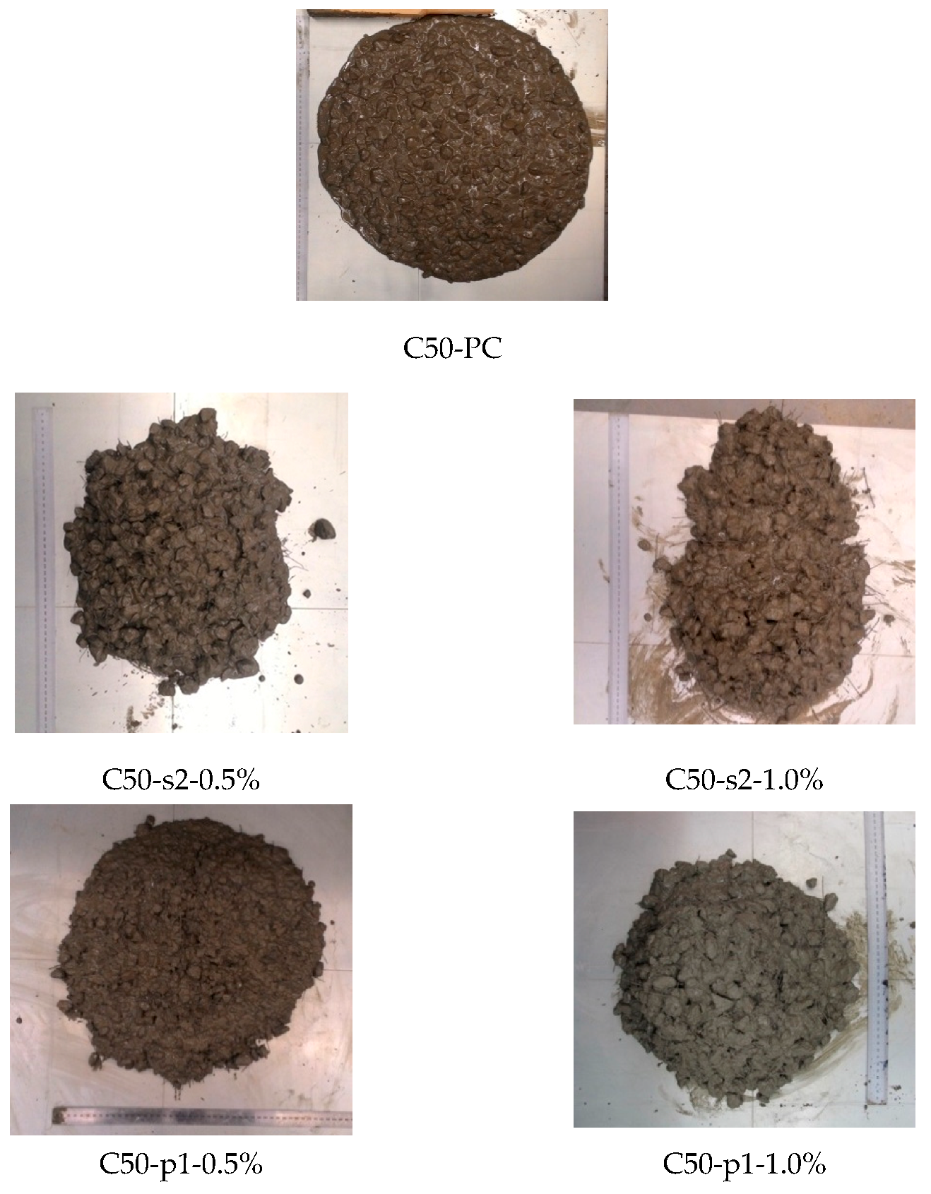
Although the steel fibers had a more adverse effect on flowability than the macro-synthetic fibers for Vf = 0.5%, there was no measurable difference between the mixes at Vf = 1%. In fact, an unexpected trend of the mean flow value, which is the average between the minimum and the maximum flow diameter, was observed for C45 and C50 mixes with s1 and s2 and C50 mixes with p2. For these mixes, average flow increased from Vf = 0.5% to Vf = 1%, indicating an apparent increase in flowability with increase in fiber content. This unexpected trend was generally more evident in the case of the steel fibers. Looking at Figure 5, it is evident that the flow shape changes from circular to elliptical with increased fiber content. The presence of an elongated flow shape in FRC can be attributed to preferential flow due to fiber alignment in one direction. Thus, for FRC systems the average flow diameter alone is not sufficient to quantify flowability and must be supplemented with an additional parameter to take into consideration the eccentricity of the final flow shape. To quantify this phenomenon, a new experimental parameter is proposed herein for FRC:
where Lmin and Lmax are the minimum and the maximum flow diameter, respectively. The closer the ratio is to 1 the more circular the shape of the flow.
ρ = Lmin/Lmax,
To better understand the importance of this parameter, the ρ ratios and corresponding CV in brackets are summarized in Table 5. It is worth mentioning that the CV of the ρ values are low, indicating good repeatability of the measurements. As expected, ρ ratios were equal to or slightly lower than 1 for PC, confirming the uniform and circular flow shape. It is also shown that both fiber types led to ρ ratios lower than that of PC, with steel fibers resulting in lower values than macro-synthetic fibers. The flexibility of the macro-synthetic fibers likely helped to maintain a more uniform concrete flow, while the steel fibers (high stiffness) interlocked and resulted in preferential flow in one direction. Additionally, the reduction of the w/c ratio led to more adverse effects by the fibers on both flow values and ρ ratios. Within the same fiber type, increasing the fiber length and the amount of fibers decreased the ρ ratio, which agrees with expected trends on flowability. Therefore, the proposed parameter can provide valuable information when implementing the DIN flow table test, where ρ ratio can give information about preferential direction of flow caused by the presence of fibers.
3.1.4. Behavior of FRC with High Workability
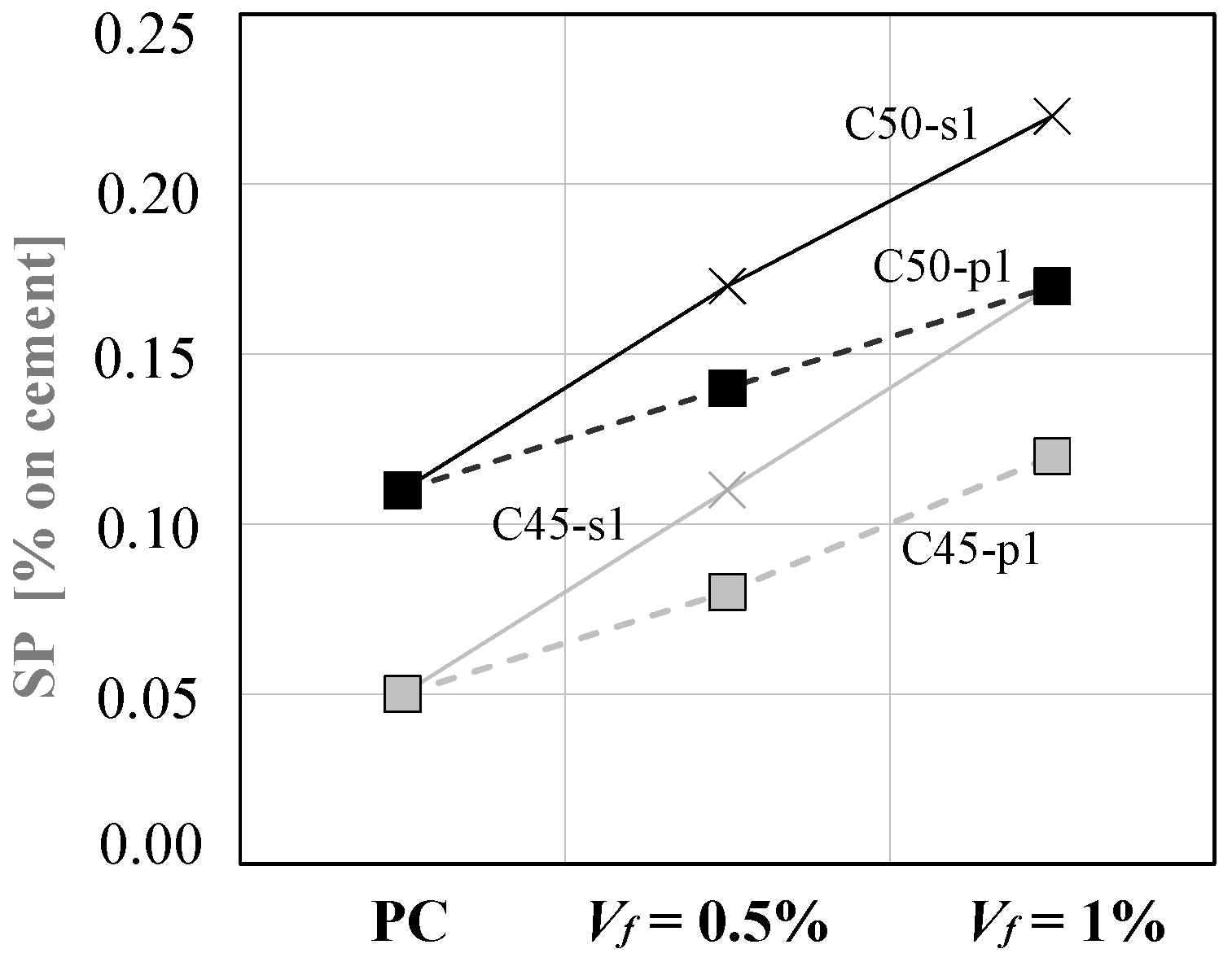
As outlined in Section 2.2, after evaluation of the fresh properties each FRC mix was adjusted with superplasticizer to obtain a target slump of 180 mm ± 20 mm, tested for air content, then finally cast in molds for mechanical testing. Figure 6 shows the amount of superplasticizer required to reach the target slump for fibers s1 and p1 in both concrete C45 and C50. It can be observed that the increase in superplasticizer demand is linear with respect to fiber content—this is in good agreement with the trend observed in Figure 3, where slump decreased with fiber addition. Moreover, steel fibers led to a greater decrease in slump than macro-synthetic fibers, which corresponds well with the higher percentage of superplasticizer required to reach the target slump in the s1 mixes compared to the p1 mixes.
Air content measurements were carried out on the modified mixes and no significant changes were observed due to the addition of superplasticizer compared to the original mixes (Table 4). Even if the slump value was restored to approximately 180 mm, the measured flow was smaller than that of PC and the ρ ratio was less than one in most cases (Table 5). This supports the value in supplementing the slump test with flow table tests for characterizing workability of FRC systems.
3.1.5. Integrating the Slump and Flow Table Test
The importance of combining the slump test (static test that provides only the consistency measurement of concrete without giving an indication of the ability of concrete to move under dynamic placing conditions) with the DIN flow table test (dynamic test that allows evaluation of the fluidity of concrete), describing the results of the latter through two parameters, is highlighted by this experimental program. All mixes had the same target slump but were found to exhibit different flow behavior. This demonstrates that the flow results of the DIN flow table test can provide more information, i.e., the effect of fiber orientation and dispersion on flow, than the slump test alone. In addition, both tests are quite simple and field-friendly, thus can be easily applied on-site.
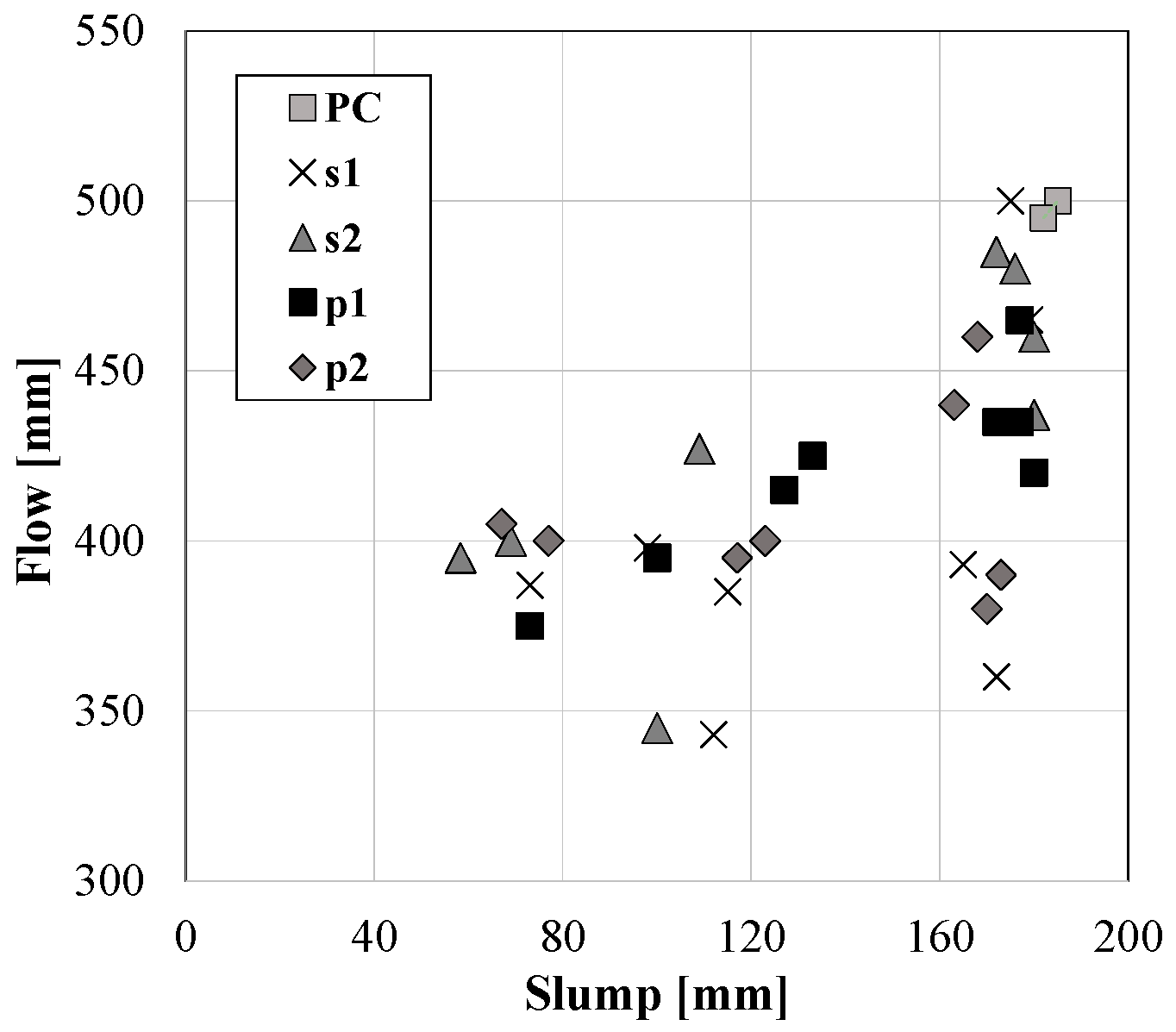
To better understand the need to perform both the slump and DIN flow table test to evaluate workability of FRC, it is worth studying a possible correlation between the experimental results. Figure 7 shows the relationship between flow and slump for the PC and FRC tested in this study. In contrast to PC, where a linear relationship between slump and flow can be generally found [55], Figure 7 shows that in the case of FRC a consistent correlation is no longer apparent. As mentioned above, the introduction of fibers led to preferential flow, thus making it necessary to supplement the measured mean flow values with visual inspection and ρ. These results provide further support that both the slump and DIN flow table tests should be performed to describe FRC workability.
3.2. Hardened State Properties of PC and FRC
Table 6 shows the results of the mechanical properties for all mixes at 28 days, with CV in brackets. Reported parameters are:
- compressive strength (fcm);
- first-peak flexural strength (f1) according to ASTM C1609 [52];
- residual flexure tensile strengths at net deflection of 0.75 mm (f150,0.75) and 3.00 mm (f150,3.00) according to ASTM C1609 [52];
- flexural toughness at net deflection of 3.00 mm (T150,3.00) according to ASTM C1609 [52].
As underlined in Section 2, the compressive strength was evaluated by testing 6 cylinders, while the other parameters were obtained by carrying out four-point bending tests on three 150 mm × 150 mm × 500 mm beams.
It can be observed that concretes C45 were characterized by an overall mean compressive strength of approximately 45.9 MPa, while for concretes C50 it was 51.1 MPa. The concrete compressive strengths were also characterized by relatively low result scatter, indicating high repeatability in the casting procedure. Also, the results indicate that the fiber addition, either steel or macro-synthetic, did not influence the compressive strength (in the range of fiber content considered). This agrees well with the results of air content, which were also not affected by the incorporation of fibers.
Concerning the flexural properties, residual flexural tensile strength results exhibited more variability than toughness results and, overall, similar values were observed in both steel and macro-synthetic fibers. A clear hardening behavior under flexure was observed only for steel fibers s1 and s2 at Vf = 1%, while macro-synthetic fibers always exhibited a softening behavior characterized by a sharp drop after the peak load followed by residual strength.
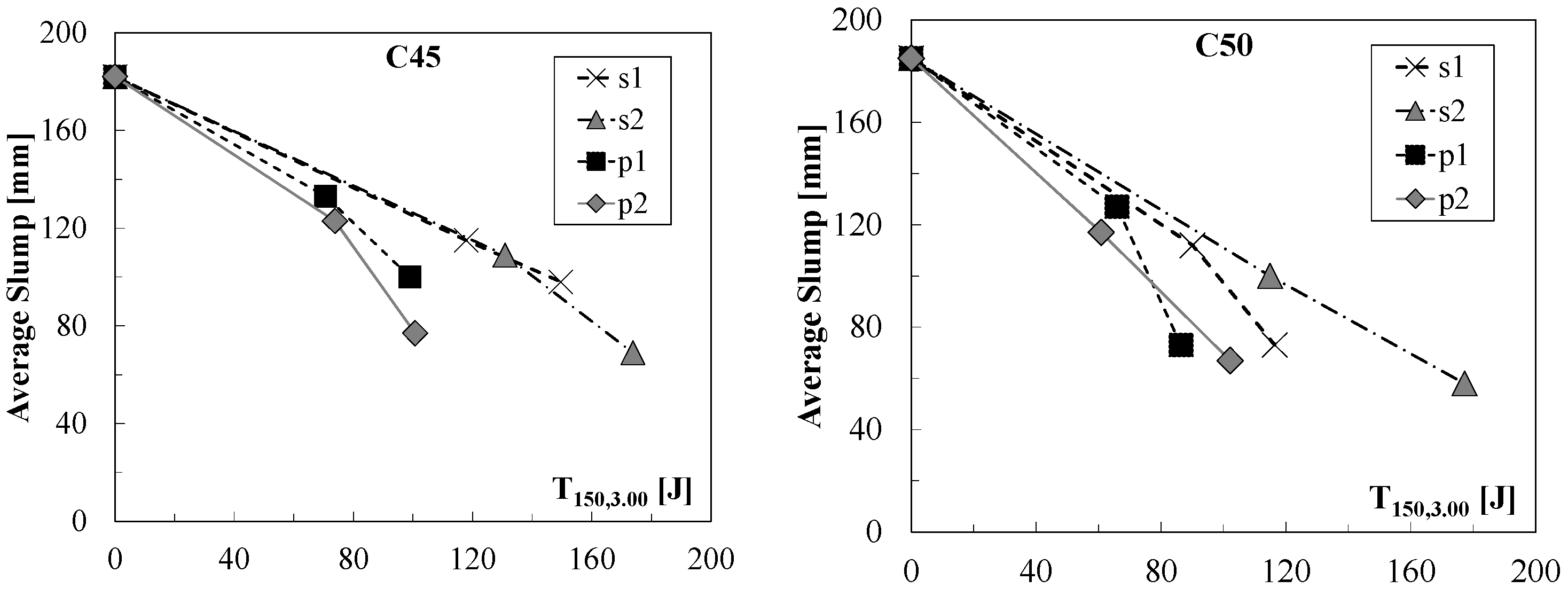
Figure 8 shows the slump values as a function of the flexural toughness (T150,3.00) for both steel and macro-synthetic fibers (flexural toughness was used since it represents the overall post-cracking behavior of FRC). This allows evaluation of the effects of the fibers themselves, i.e., independent of fiber content, on concrete workability considering the different FRCs as composite materials (matrix + fibers). As expected, the relation between slump and toughness is dependent on fiber type and length. However, it can be observed that, for a given flexural toughness, macro-synthetic fibers affect concrete workability more as compared to steel ones. This is opposite to the results underlined in Section 3, which can be tied to the high content of macro-synthetic fibers needed to reach post-cracking mechanical performances similar to the ones provided by steel fibers. In addition, it seems that, in the ranges considered, steel fibers have a linear slump reduction with toughness increase, while this trend changes in the case of macro-synthetic fibers (with a more pronounced reduction for value of T150,3.00 greater than 70 J).
4. Conclusions
The properties of FRC systems incorporating steel (high stiffness) and macro-synthetic (low stiffness) fibers in two base concrete systems (C45 and C50) were herein investigated. The main findings are summarized in the following:
- Both steel and macro-synthetic fibers (up to 1% of volume fraction) led to a slight increase in air content as compared to the plain concretes, indicating that the influence of fibers was negligible. This was supported by the compressive strength results, where all PC and FRC mixes within each concrete base mix exhibited very similar strength.
- For a given fiber volume fraction, concrete workability was overall more affected by steel fibers than macro-synthetic ones. On the contrary, for a target flexural toughness, steel fibers influenced concrete workability less as compared to polypropylene ones.
- For a given aspect ratio and fiber volume fraction, longer fibers (both steel and macro-synthetic) caused a greater increase in concrete stiffness as compared to shorter fibers.
- Concrete flow behavior differed between SFRC and PFRC mixes, where SFRC mixes exhibited a less uniform spread overall. This may be attributed to the steel fibers re-orienting and interlocking, resulting in flow in a preferential direction and the final spread forming an elongated shape.
- The DIN flow table test may be used in situ to evaluate the fluidity of FRC as an extension of the static slump test. However, it should be supplemented with an additional parameter—the ratio between the diameters along the two axes of symmetry (ρ)—to describe any potential preferential flow direction.
- Unlike for PC systems, DIN flow table and slump test measurements did not show any apparent correlation in the case of FRC systems.
Author Contributions
V.G., A.C., G.P. and S.K. designed the experiments; V.G. performed all the experiments; V.G., A.C., G.P. and S.K. analyzed the experimental results; V.G. and A.C. wrote the paper; A.C., G.P. and S.K. reviewed and edited the final paper.
Funding
This research received no external funding.
Acknowledgments
The authors are grateful to BASF Construction Chemicals and Euclid Chemical for the materials provided, as well as the technical support by the staff of Carleton Laboratory at Columbia University. Furthermore, a special acknowledgement goes also to the University of Brescia for the economic support during the period of the project.
Conflicts of Interest
The authors declare no conflict of interest.
References
- Cuenca, E.; Echegaray-Oviedo, J.; Serna, P. Influence of concrete matrix and type of fiber on the shear strength behavior of self-compacting fiber reinforced concrete. Compos. Part B Eng. 2015, 75, 135–147. [Google Scholar] [CrossRef]
- Watanabe, K.; Kimura, T.; Niwa, J. Synergetic effect of steel fibers and shear reinforcing bars on the shear-resistance mechanisms of RC linear members. Constr. Build. Mater. 2010, 24, 2369–2375. [Google Scholar] [CrossRef]
- Ding, Y.; You, Z.; Jalali, S. The composite effect of steel fibres and stirrups on the shear behaviour of beams using self-consolidating concrete. Eng. Struct. 2011, 33, 107–117. [Google Scholar] [CrossRef]
- Slater, E.; Moni, M.; Alam, M.S. Predicting the shear strength of steel fiber reinforced concrete beams. Constr. Build. Mater. 2012, 26, 423–436. [Google Scholar] [CrossRef]
- Chalioris, C.E. Steel fibrous RC beams subjected to cyclic deformations under predominant shear. Eng. Struct. 2013, 49, 104–118. [Google Scholar] [CrossRef]
- Chalioris, C.E. Analytical approach for the evaluation of minimum fibre factor required for steel fibrous concrete beams under combined shear and flexure. Constr. Build. Mater. 2013, 43, 317–336. [Google Scholar] [CrossRef]
- Sorelli, L.G.; Meda, A.; Plizzari, G.A. Steel fiber concrete slabs on ground: A structural matter. ACI Struct. J. 2006, 103, 551–558. [Google Scholar]
- Caratelli, A.; Meda, A.; Rinaldi, Z.; Romualdi, P. Structural behavior of precast tunnel segments in fiber reinforced concrete. Tunn. Undergr. Space Technol. 2011, 26, 284–291. [Google Scholar] [CrossRef]
- ACI Committee 544. Report on Fiber Reinforced Concrete ACI Report 544.1R-96; Technical Report; American Concrete Institute: Farmington Hills, MI, USA, 1996; p. 66. [Google Scholar]
- Guidelines for the Design, Construction and Production Control of Fiber Reinforced Concrete Structures; CNR DT 204; National Research Council of Italy: Roma, Italy, 2006; p. 59.
- Deutscher Ausschuss für Stahlbeton (DAfStb). DAfStb Guideline: German Committee for Reinforced Concrete, Steel Fiber Reinforced Concrete; Design and Construction, Specification, Performance, Production and Conformity, Execution of Structures—Draft; Deutscher Ausschuss für Stahlbeton: Berlin, Germany, 2012; 48p. [Google Scholar]
- Instrucción de hormigón estructural EHE-08; Comisión Permanente del Hormigón, Ministerio de Fomento: Madrid, Spain, 2011; p. 670.
- Model Code 2010—Final Draft; fib Bulletin 65; fib: Lausanne, Switzerland, 2012; Volume 1, 350p, ISBN 978-2-88394-105-2.
- Model Code 2010—Final Draft; fib Bulletin 66; fib: Lausanne, Switzerland, 2012; Volume 2, 370p, ISBN 978-2-88394-106-9.
- Ortiz-Navas, F.; Navarro-Gregori, J.; Leiva-Herdocia, G.E.; Serna, P.; Cuenca, E. An experimental study on the shear behaviour of reinforced concrete beams with macro-synthetic fibres. Constr. Build. Mater. 2018, 169, 888–899. [Google Scholar] [CrossRef]
- Conforti, A.; Tiberti, G.; Plizzari, G.A.; Caratelli, A.; Meda, A. Precast tunnel segments reinforced by macro-synthetic fibers. Tunn. Undergr. Space Technol. 2017, 63, 1–11. [Google Scholar] [CrossRef]
- Farhan, N.A.; Sheikh, M.N.; Hadi, M.S.D. Engineering properties of ambient cured alkali-activated fly ash-slag concrete reinforced with different types of steel fiber. J. Mater. Civ. Eng. 2018, 30, 04018142. [Google Scholar] [CrossRef]
- Farhan, N.A.; Sheikh, M.N.; Hadi, M.S.D. Experimental Investigation on the Effect of Corrosion on the Bond Between Reinforcing Steel Bars and Fibre Reinforced Geopolymer Concrete. Structures 2018, 14, 251–261. [Google Scholar] [CrossRef]
- Farhan, N.A.; Sheikh, M.N.; Hadi, M.S.D. Design of geopolymer concrete with GGBFS at ambient curing condition using Taguchi method. Constr. Build. Mater. 2017, 140, 424–431. [Google Scholar]
- Ortega, J.M.; Sanchez, I.; Anton, C.; de Vera, G.; Climent, G.A. Influence of environment on durability of fly ash cement mortars. ACI Mater. J. 2012, 109, 647–656. [Google Scholar]
- Sanchez, I.; Anton, C.; de Vera, G.; Ortega, J.M.; Climent, G.A. Moisture distribution in partially saturated concrete studied by impedance spectroscopy. J. Nondestruct. Eval. 2013, 32, 362–371. [Google Scholar] [CrossRef] [Green Version]
- Williams, M.; Ortega, J.M.; Sanchez, I.; Cabeza, M.; Climent, G.A. Non-Destructive Study of the Microstructural Effects of Sodium and Magnesium Sulphate Attack on Mortars Containing Silica Fume Using Impedance Spectroscopy. Appl. Sci. 2017, 7, 648. [Google Scholar] [CrossRef]
- Cuenca, E.; Ferrara, L. Self-healing capacity of fiber reinforced cementitious composites. State of the art and perspectives. KSCE J. Civ. Eng. 2017, 21, 2777–2789. [Google Scholar] [CrossRef] [Green Version]
- Cuenca, E.; Tejedor, A.; Ferrara, L. A methodology to assess crack-sealing effectiveness of crystalline admixtures under repeated cracking-healing cycles. Constr. Build. Mater. 2018, 179, 619–632. [Google Scholar] [CrossRef]
- Hughes, B.P.; Fattuhi, N.I. The workability of steel-fiber-reinforced concrete. Mag. Concr. Res. 1976, 28, 157–161. [Google Scholar] [CrossRef]
- Bentur, A.; Mindess, S. Fiber Reinforced Cementitious Composites; Taylor & Francis Group: Abingdon, UK, 2007; p. 601. ISBN 0-415-25048-X. [Google Scholar]
- Mehta, K.P.; Monteiro, P.J.M. Concrete: Microstructure, Properties and Materials; McGraw-Hill: New York, NY, USA, 2005; p. 659. ISBN 0071797874. [Google Scholar]
- Ferrara, L.; Meda, A. Relationships between fiber distribution, workability and the mechanical properties of SFRC applied to precast roof elements. Mater. Struct. 2006, 39, 411–420. [Google Scholar] [CrossRef]
- Johnston, C.D. Measures of the Workability of Steel Fiber Reinforced Concrete and their Precision. Cem. Concr. Aggreg. 1984, 6, 74–83. [Google Scholar]
- Balaguru, P.; Ramakrishnan, V. Comparison of slump cone and V-B tests as measures of workability for fiber-reinforced and plain concrete. Cem. Concr. Aggreg. CCAGDP 1987, 9, 3–11. [Google Scholar]
- Balaguru, P.; Ramakrishnan, V. Properties of fiber reinforced concrete: Workability, Behavior under long-term loading, and air-void characteristics. ACI Mater. J. 1988, 85, 189–196. [Google Scholar]
- Sachan, A.K.; Kameswara Rao, C.V.S. A cone penetration test for workability of fiber reinforced concrete. Mater. Struct. 1988, 21, 448–452. [Google Scholar] [CrossRef]
- Bayasi, M.Z.; Soroushian, P. Effect of steel fiber reinforcement on fresh mix properties of concrete. ACI Mater. J. 1992, 89, 369–374. [Google Scholar]
- Pasini, F.; Garcia, T.; Gettu, R.; Agulló, L. Experimental study of the properties of flowable fiber reinforced concretes. In Proceedings of the Sixth RILEM International Symposium (BEFIB 2004), Varenna, Italy, 20–22 September 2004. [Google Scholar]
- Szwabowski, J.; Ponikiewski, T. The rheological properties of fresh polypropylene fiber reinforced mortar and concrete. In Proceedings of the Sixth RILEM International Symposium (BEFIB 2004), Varenna, Italy, 20–22 September 2004. [Google Scholar]
- Mohammadi, Y.; Singh, S.P.; Kaushik, S.K. Properties of steel fibrous concrete containing mixed fibers in fresh and hardened state. Constr. Build. Mater. 2007, 22, 956–965. [Google Scholar] [CrossRef]
- Laskar, A.I. Correlating slump, slump flow, Vebe and Flow tests to rheological parameters of high-performance concrete. Mater. Res. 2009, 12, 75–81. [Google Scholar] [CrossRef]
- De Figueiredo, A.D.; Ceccato, M.R. Workability analysis of steel fiber reinforced concrete using slump and Ve-Be test. Mater. Res. 2015, 18, 1284–1290. [Google Scholar] [CrossRef]
- Glanville, W.H.; Collins, A.R.; Matthews, D.D. The Grading of Aggregates and Workability of Concrete; Road Research Technical Paper; H.M.S.O.: London, UK, 1947. [Google Scholar]
- Shah, S.P.; Daniel, J.I.; Ahmad, S.H.; Arockiasamy, M.; Balaguru, P.N.; Ball, C.G.; Ball, H.P.; Batson, G.B.; Bentur, A.; Craig, R.J.; et al. Measurement of properties of fiber reinforced concrete. ACI Mater. J. 1988, 85, 583–593. [Google Scholar]
- Graf, O. Experiments of the behavior of Reinforcement in Concrete of Various Compositions. Deutsch. Aussch. Eisenbeton 1933, 71, 37–60. [Google Scholar]
- Testing Fresh Concrete—Part 5: Flow Table Test; EN 12350-5; Deutsches Institut fur Normung E.V. (DIN): Berlin, Germany, 2009.
- Martinie, L.; Rossi, P.; Roussel, N. Rheology of fiber reinforced cementitious materials: Classification and prediction. Cem. Concr. Res. 2010, 40, 226–234. [Google Scholar] [CrossRef]
- Kuder, K.G.; Ozyurt, N.; Mu, E.B.; Shah, S.P. Rheology of fiber-reinforced cementitious materials. Cem. Concr. Res. 2007, 37, 191–199. [Google Scholar] [CrossRef]
- Haist, M.; Ferrara, L. Rheological characterization of high performance fiber reinforced cementitious composites. In Proceedings of the Eighth RILEM International Symposium (BEFIB 2012), Guimaraes, Portugal, 19–21 September 2012. [Google Scholar]
- Page, J.; Khadraoui, F.; Boutouil, M.; Gomina, M. Multi-physical properties of a structural concrete incorporating short flax fibers. Constr. Build. Mater. 2017, 140, 344–353. [Google Scholar] [CrossRef]
- Ferrara, L.; Park, Y.D.; Shah, S.P. A method for mix-design of fiber-reinforced self-compacting concrete. Cem. Concr. Res. 2007, 37, 957–971. [Google Scholar] [CrossRef]
- Standard Test Method for Air Content of Freshly Mixed Concrete by the Pressure Method; ASTM C231; ASTM International: West Conshohocken, PA, USA, 2017.
- Standard Test Method for Slump of Hydraulic-Cement Concrete; ASTM C143; ASTM International: West Conshohocken, PA, USA, 2015.
- Testing Fresh Concrete—Part 2: Slump-Test; EN 12350-2; BSI: London, UK, 2009.
- Standard Practice for Making and Curing Concrete Test Specimens in the Laboratory; ASTM C192; ASTM International: West Conshohocken, PA, USA, 2016.
- Standard Test Method for Flexural Performance of Fiber-Reinforced Concrete (Using Beam with Third-Point Loading); ASTM C1609; ASTM International: West Conshohocken, PA, USA, 2012.
- Standard Test Method for Compressive Strength of Cylindrical Concrete Specimens; ASTM C39; ASTM International: West Conshohocken, PA, USA, 2016.
- Concrete—Specification, Performance, Production and Conformity; EN 206-1; BSI: London, UK, 2013.
- Mor, A.; Ravina, D. The DIN Flow Table. Concr. Int. 1986, 8, 53–56. [Google Scholar]
Figure 1.
Steel fibers (s1, s2) and macro-synthetic fibers (p1, p2) used in this study.

Figure 2.
Air content measurement of plain concrete (PC) and fiber reinforced concretes for Vf = 0.5% and Vf = 1%.
Figure 2.
Air content measurement of plain concrete (PC) and fiber reinforced concretes for Vf = 0.5% and Vf = 1%.

Figure 3.
Influence of fibers on slump reduction in concrete C45 (left) and C50 (right) in case of plain concrete (PC) and fiber reinforced concretes (Vf = 0.5% and Vf = 1%).
Figure 3.
Influence of fibers on slump reduction in concrete C45 (left) and C50 (right) in case of plain concrete (PC) and fiber reinforced concretes (Vf = 0.5% and Vf = 1%).

Figure 4.
Influence of fibers on flow reduction in concrete C45 (left) and C50 (right) in case of plain concrete (PC) and fiber reinforced concretes (Vf = 0.5% and Vf = 1%).
Figure 4.
Influence of fibers on flow reduction in concrete C45 (left) and C50 (right) in case of plain concrete (PC) and fiber reinforced concretes (Vf = 0.5% and Vf = 1%).

Figure 5.
DIN flow table test of concrete C50 reinforced by fibers s2 and p1.

Figure 6.
Superplasticizer (SP) dosage necessary for FRC (Vf = 0.5% and Vf = 1%) to obtain the same slump as PC (180 ± 20 mm).
Figure 6.
Superplasticizer (SP) dosage necessary for FRC (Vf = 0.5% and Vf = 1%) to obtain the same slump as PC (180 ± 20 mm).

Figure 7.
Relationship between flow and slump for PC and FRC.

Figure 8.
Slump value vs. flexural toughness (T150,3.00) for concrete C45 (left) and C50 (right) in case of plain concrete (PC) and fiber reinforced concretes (Vf = 0.5% and Vf = 1%).
Figure 8.
Slump value vs. flexural toughness (T150,3.00) for concrete C45 (left) and C50 (right) in case of plain concrete (PC) and fiber reinforced concretes (Vf = 0.5% and Vf = 1%).


Table 1.
Mix design of base concrete C45 and C50.
| Concrete | C45 | C50 |
|---|---|---|
| Sand 0–4.75 [kg/m3] | 690 | 730 |
| Coarse aggregate 4.75–25 [kg/m3] | 992 | 992 |
| Maximum Aggregate Size [mm] | 25 | 25 |
| Cement Type | Type I | Type I |
| Cement Content [kg/m3] | 429 | 429 |
| Water-Cement Ratio 1 | 0.50 | 0.45 |
| Superplasticizer (% of cement content) | 0.05 | 0.11 |
1 Aggregates in saturated-surface-dry condition.
Table 2.
Characteristics of steel and macro-synthetic fibers used in this study.
| Fiber Designation | s1 | s2 | p1 | p2 |
|---|---|---|---|---|
| Type | Steel | Steel | Polypropylene | Polypropylene |
| Shape | Hooked-End | Hooked-End | Crimped | Embossed |
| Length l [mm] | 35 | 60 | 40 | 54 |
| Diameter Ø [mm] | 0.54 | 0.92 | 0.75 | 0.81 |
| Aspect Ratio l/Ø | 65 | 65 | 53 | 67 |
| Tensile Strength [MPa] | >1345 | >1100 | >450 | >552 |
| Elastic Modulus [GPa] | 210 | 210 | 3.6 | 6 |
| Density [kg/m3] | 7850 | 7850 | 910 | 910 |
Table 3.
Concrete designation and fiber content.
| Designation | Base Concrete | Fiber | Fiber Content [kg/m3] | Vf [%] |
|---|---|---|---|---|
| C45 | ||||
| C45-PC | C45 | - | 0 | 0 |
| C45-s1-0.5% | C45 | s1 | 39.2 | 0.5 |
| C45-s1-1.0% | C45 | s1 | 78.5 | 1.0 |
| C45-s2-0.5% | C45 | s2 | 39.2 | 0.5 |
| C45-s2-1.0% | C45 | s2 | 78.5 | 1.0 |
| C45-p1-0.5% | C45 | p1 | 4.6 | 0.5 |
| C45-p1-1.0% | C45 | p1 | 9.1 | 1.0 |
| C45-p2-0.5% | C45 | p2 | 4.6 | 0.5 |
| C45-p2-1.0% | C45 | p2 | 9.1 | 1.0 |
| C50 | ||||
| C50-PC | C50 | - | 0 | 0 |
| C50-s1-0.5% | C50 | s1 | 39.2 | 0.5 |
| C50-s1-1.0% | C50 | s1 | 78.5 | 1.0 |
| C50-s2-0.5% | C50 | s2 | 39.2 | 0.5 |
| C50-s2-1.0% | C50 | s2 | 78.5 | 1.0 |
| C50-p1-0.5% | C50 | p1 | 4.6 | 0.5 |
| C50-p1-1.0% | C50 | p1 | 9.1 | 1.0 |
| C50-p2-0.5% | C50 | p2 | 4.6 | 0.5 |
| C50-p2-1.0% | C50 | p2 | 9.1 | 1.0 |
Table 4.
Fresh state properties of concrete C45 and C50 (CV in brackets).
| Concrete Designation | Base Concrete + Fibers | Slump Target 180 ± 20 mm | ||||
|---|---|---|---|---|---|---|
| Air Content [%] | Slump [mm] | Flow [mm] | Air Content [%] | Slump [mm] | Flow [mm] | |
| C45 | ||||||
| C45-PC | 2.7 (0.02) | 182 (0.01) | 495 (0.01) | - | - | - |
| C45-s1-0.5% | 2.7 (0.04) | 115 (0.06) | 385 (0.02) | 2.4 (0.05) | 179 (0.05) | 465 (0.04) |
| C45-s1-1.0% | 2.8 (0.06) | 98 (0.06) | 398 (0.02) | 2.9 (0.08) | 175 (0.02) | 500 (0.02) |
| C45-s2-0.5% | 2.7 (0.06) | 109 (0.06) | 428 (0.03) | 2.4 (0.05) | 180 (0.05) | 437 (0.02) |
| C45-s2-1.0% | 2.9 (0.04) | 69 (0.19) | 400 (0.07) | 2.5 (0.04) | 176 (0.03) | 480 (0.04) |
| C45-p1-0.5% | 2.9 (0.08) | 133 (0.03) | 425 (0.04) | 3.0 (0.05) | 177 (0.03) | 435 (0.09) |
| C45-p1-1.0% | 3.2 (0.06) | 100 (0.08) | 395 (0.04) | 3.0 (0.05) | 180 (0.01) | 420 (0.03) |
| C45-p2-0.5% | 2.8 (0.03) | 123 (0.04) | 395 (0.01) | 2.7 (0.04) | 173 (0.03) | 395 (0.05) |
| C45-p2-1.0% | 3.0 (0.03) | 77 (0.06) | 400 (0.01) | 3.1 (0.06) | 163 (0.03) | 440 (0.02) |
| C50 | ||||||
| C50-PC | 2.4 (0.02) | 185 (0.02) | 500 (0.01) | - | - | - |
| C50-s1-0.5% | 2.4 (0.05) | 112 (0.08) | 343 (0.06) | 2.7 (0.08) | 172 (0.08) | 360 (0.05) |
| C50-s1-1.0% | 2.9 (0.08) | 73 (0.06) | 388 (0.06) | 2.8 (0.05) | 165 (0.07) | 393 (0.04) |
| C50-s2-0.5% | 2.4 (0.06) | 100 (0.22) | 345 (0.03) | 2.2 (0.03) | 180 (0.02) | 460 (0.02) |
| C50-s2-1.0% | 2.5 (0.04) | 58 (0.28) | 395 (0.05) | 2.9 (0.05) | 172 (0.06) | 485 (0.02) |
| C50-p1-0.5% | 2.9 (0.09) | 127 (0.05) | 415 (0.05) | 3.6 (0.07) | 172 (0.04) | 435 (0.03) |
| C50-p1-1.0% | 3.0 (0.06) | 73 (0.06) | 375 (0.05) | 3.2 (0.05) | 177 (0.03) | 465 (0.03) |
| C50-p2-0.5% | 2.8 (0.06) | 117 (0.08) | 400 (0.08) | 2.8 (0.05) | 173 (0.03) | 390 (0.04) |
| C50-p2-1.0% | 3.1 (0.07) | 67 (0.19) | 405 (0.05) | 3.0 (0.06) | 170 (0.01) | 465 (0.02) |
Table 5.
ρ ratio for PC and FRC with different fiber types.
| Concrete | Base Concrete + Fibers | Slump Target 180 mm ± 20 mm | ||||||
|---|---|---|---|---|---|---|---|---|
| 0.5% | 1.0% | 0.5% | 1.0% | |||||
| C45 | C50 | C45 | C50 | C45 | C50 | C45 | C50 | |
| PC | 0.98 (0.01) | 0.99 (0.01) | 0.98 (0.01) | 0.99 (0.01) | - | - | - | - |
| s1 | 0.97 (0.01) | 0.80 (0.02) | 0.92 (0.03) | 0.72 (0.05) | 0.95 (0.01) | 0.99 (0.01) | 0.88 (0.05) | 0.82 (0.05) |
| s2 | 0.97 (0.01) | 0.84 (0.03) | 0.90 (0.02) | 0.72 (0.10) | 0.94 (0.01) | 0.99 (0.01) | 0.93 (0.02) | 0.94 (0.04) |
| p1 | 0.93 (0.04) | 0.98 (0.01) | 0.93 (0.02) | 0.97 (0.00) | 0.98 (0.01) | 0.98 (0.03) | 0.96 (0.04) | 0.98 (0.03) |
| p2 | 0.93 (0.04) | 0.93 (0.03) | 0.90 (0.03) | 0.90 (0.04) | 0.98 (0.02) | 0.95 (0.04) | 0.99 (0.02) | 0.98 (0.01) |
Table 6.
Compressive strength (fcm), flexural tensile strength (fl), residual flexural strengths (f150,0.75 and f150,3.00) and toughness (T150,3.00) evaluated according to ASTM C1609.
Table 6.
Compressive strength (fcm), flexural tensile strength (fl), residual flexural strengths (f150,0.75 and f150,3.00) and toughness (T150,3.00) evaluated according to ASTM C1609.
| Concrete | fcm | fl | f150,0.75 | f150,3.00 | T150,3.00 |
|---|---|---|---|---|---|
| [MPa] | [MPa] | [MPa] | [MPa] | [J] | |
| C45 | |||||
| C45-PC | 42.84 (0.05) | 5.40 (0.06) | - | - | - |
| C45-s1-0.5% | 46.57 (0.01) | 5.38 (0.07) | 5.98 (0.05) | 3.67 (0.06) | 117.9 (0.04) |
| C45-s1-1.0% | 46.84 (0.02) | 6.70 (0.09) | 7.74 (0.12) | 4.80 (0.11) | 149.6 (0.13) |
| C45-s2-0.5% | 43.68 (0.02) | 5.59 (0.07) | 6.13 (0.09) | 4.73 (0.16) | 130.9 (0.12) |
| C45-s2-1.0% | 46.48 (0.02) | 5.95 (0.06) | 8.81 (0.10) | 6.23 (0.06) | 173.8 (0.08) |
| C45-p1-0.5% | 46.65 (0.01) | 5.62 (0.04) | 2.68 (0.19) | 2.79 (0.15) | 70.7 (0.13) |
| C45-p1-1.0% | 48.83 (0.01) | 5.77 (0.03) | 3.59 (0.19) | 4.20 (0.19) | 99.0 (0.15) |
| C45-p2-0.5% | 44.66 (0.03) | 6.43 (0.01) | 3.16 (0.25) | 2.84 (0.12) | 73.8 (0.15) |
| C45-p2-1.0% | 46.37 (0.02) | 5.66 (0.07) | 3.92 (0.11) | 4.28 (0.08) | 100.7 (0.05) |
| C50 | |||||
| C50-PC | 49.97 (0.03) | 6.10 (0.04) | - | - | - |
| C50-s1-0.5% | 53.27 (0.01) | 5.60 (0.06) | 4.62 (0.09) | 3.02 (0.08) | 90.1 (0.03) |
| C50-s1-1.0% | 48.62 (0.02) | 5.48 (0.03) | 5.77 (0.07) | 3.84 (0.10) | 116.4 (0.06) |
| C50-s2-0.5% | 52.21 (0.04) | 6.04 (0.06) | 5.83 (0.11) | 4.04 (0.13) | 114.9 (0.08) |
| C50-s2-1.0% | 47.17 (0.03) | 6.41 (0.05) | 8.54 (0.11) | 6.50 (0.05) | 177.2 (0.09) |
| C50-p1-0.5% | 54.97 (0.01) | 6.37 (0.02) | 2.58 (0.16) | 2.56 (0.09) | 65.9 (0.09) |
| C50-p1-1.0% | 55.04 (0.06) | 6.43 (0.08) | 3.39 (0.29) | 3.60 (0.23) | 86.4 (0.22) |
| C50-p2-0.5% | 49.86 (0.01) | 6.35 (0.07) | 2.35 (0.03) | 2.23 (0.13) | 60.8 (0.04) |
| C50-p2-1.0% | 48.35 (0.03) | 6.39 (0.09) | 4.18 (0.32) | 4.27 (0.29) | 102.1 (0.29) |
© 2018 by the authors. Licensee MDPI, Basel, Switzerland. This article is an open access article distributed under the terms and conditions of the Creative Commons Attribution (CC BY) license (http://creativecommons.org/licenses/by/4.0/).
Share and Cite
MDPI and ACS Style
Guerini, V.; Conforti, A.; Plizzari, G.; Kawashima, S. Influence of Steel and Macro-Synthetic Fibers on Concrete Properties. Fibers 2018, 6, 47. https://0-doi-org.brum.beds.ac.uk/10.3390/fib6030047
AMA Style
Guerini V, Conforti A, Plizzari G, Kawashima S. Influence of Steel and Macro-Synthetic Fibers on Concrete Properties. Fibers. 2018; 6(3):47. https://0-doi-org.brum.beds.ac.uk/10.3390/fib6030047
Chicago/Turabian StyleGuerini, Veronica, Antonio Conforti, Giovanni Plizzari, and Shiho Kawashima. 2018. "Influence of Steel and Macro-Synthetic Fibers on Concrete Properties" Fibers 6, no. 3: 47. https://0-doi-org.brum.beds.ac.uk/10.3390/fib6030047
Note that from the first issue of 2016, this journal uses article numbers instead of page numbers. See further details here.