Article

A Time-Efficient Dip Coating Technique for the Deposition of Microgels onto the Optical Fiber Tip

1
Optoelectronics Group, Department of Engineering, University of Sannio, 82100 Benevento, Italy
2
ENEA, Portici Research Center, P.le E. Fermi 1, 80055 Napoli, Italy
3
Institute of Biostructure and Bioimaging, National Research Council, 80143 Napoli, Italy
*
Authors to whom correspondence should be addressed.
Submission received: 1 August 2018 / Revised: 21 September 2018 / Accepted: 23 September 2018 / Published: 28 September 2018
(This article belongs to the Special Issue Smart Coatings on Fibers and Textiles)

Abstract

:
The combination of responsive microgels and Lab-on-Fiber devices represents a valuable technological tool for developing advanced optrodes, especially useful for biomedical applications. Recently, we have reported on a fabrication method, based on the dip coating technique, for creating a microgels monolayer in a controlled fashion onto the fiber tip. In the wake of these results, with a view towards industrial applications, here we carefully analyze, by means of both morphological and optical characterizations, the effect of each fabrication step (fiber dipping, rinsing, and drying) on the microgels film properties. Interestingly, we demonstrate that it is possible to significantly reduce the duration (from 960 min to 31 min) and the complexity of the fabrication procedure, without compromising the quality of the microgels film at all. Repeatability studies are carried out to confirm the validity of the optimized deposition procedure. Moreover, the new procedure is successfully applied to different kinds of substrates (patterned gold and bare optical fiber glass), demonstrating the generality of our findings. Overall, the results presented in this work offer the possibility to improve of a factor ~30 the fabrication throughput of microgels-assisted optical fiber probes, thus enabling their possible exploitation in industrial applications.

1. Introduction

Integrating onto the optical fiber tip resonant nanostructures able to trap light at specific wavelengths is at the base of the Lab-on-Fiber (LOF) technology [1,2,3,4,5,6]. The resulting electromagnetic field confinement at sub-wavelength scale strongly enhances the light matter interaction, making possible to detect environmental changes onto the fiber surface as resonance wavelength shifts and/or intensity variation of the optical signal coupled to the fiber [4,5]. In this manner, ultra-sensitive optrodes based on LOF technology have been developed and exploited in biochemical applications, i.e., for detecting the presence of nano-sized bio-coating film resulting from molecular interactions. Moreover, as the optical fiber is, by nature, compatible with medical needles or catheters, this class of devices lends itself to in vivo detection [7].
The detection performances (such as limit of detection and response time) of LOF devices can be improved by exploiting functional materials used in combination with the resonant nanostructures. In this framework, we have recently proposed a LOF optrode integrated with microgels (MGs), i.e., ‘smart’ or responsive polymers, that change their size following environment changes [8,9,10,11,12]. Specifically, MGs are colloidal microsized hydrogel particles, which are synthesized to be selectively sensitive to physical (temperature) or chemical (i.e., pH variations, molecular binding events) parameters of interest when immersed in a liquid environment [13,14]. In biochemical applications, functionalized MGs offer the possibility to increase the target analyte loading capacity, and amplify the transduction of the optical signals [15,16,17]. In fact, in the case of MG assisted LOF optrodes, the resonance wavelengths are modulated by the MGs swelling/shrinking induced by the molecular binding, and not by the molecular binding itself occurring at the fiber surface [8].
In a previous work, we have reported a reliable fabrication strategy, based on the dip coating technique, for realizing, in a controlled fashion, monolayers of MGs onto the optical fiber tip [11]. The formation of the MGs film was controlled by selecting the parameters of the MGs solutions used during the dipping procedure. In particular, by setting low operating pH (3), low temperature (10 °C) and high concentration (5%) of particle dispersions, we achieved high coverage factor (CF) films. We have demonstrated that CFs larger than 90% warranted the maximum degree of light-MGs interactions onto the fiber tip, and thus the maximum responsivity to MGs swelling/collapsing induced by the specific external stimulus of interest [11,12].
However, the dip coating procedure used was very time consuming (about 15 h, excepting the dipping step) and it required the use of controlled temperature environment (oven) for the drying phase. In fact, the procedure started by dipping the fiber into the MGs dispersion for 1 h. Once the fiber probe was extracted, it was dried at a controlled temperature (45 °C) into an oven for 1 h. Then the probe was immersed in a deionized water bath for 12 h at room temperature under magnetic stirring in order to ensure breaking up of a possible multilayer. Finally, the probe was dried into an oven at 30 °C for 2 h. Although more fibers can be in principle deposited in parallel at the same time, the use of such time consuming process strongly limits the large scale production of LOF optrodes assisted by MGs.
With the aim of overcoming this limitation and improving the fabrication throughput, here we carefully analyze the influence of all the steps (dipping, rinsing, and drying) involved in the deposition procedure. Interestingly, we demonstrate that it is possible to significantly reduce the fabrication time while maintaining the same quality standard of the MGs films created onto the fiber tip surface. Specifically, we found that the MGs assisted optical fiber probe production throughput can be enhanced up to a factor ~30, without resorting to controlled temperature instruments during the drying phase. It is important to point out that optical monitoring of the probes during the fabrication procedure is made easy by remote interrogation and monitoring of optical fiber platforms. The optimized procedure is independent from the adhesion substrate onto the fiber tip. In fact, we have also successfully applied the optimized procedure for depositing the MGs layer onto the bulk optical fiber, i.e., directly onto the glass facet, where no gold layer was deposited. It’s worth mentioning that the overall fabrication time needed to make an optrode, including MGs synthesis and probe fabrication, clearly depends on the choice of substrate. In fact, procedures such as titanium/gold coating and FIB patterning or silanization of bare fiber have different durations as specified in the materials and method section. Overall, the results presented in this work set the stage for the large scale production of MGs assisted optical fiber probes in industrial applications.

2. Materials and Methods

2.1. Microgel Synthesis and Characterization

For MG synthesis we used poly(Nisopropylacrylamide) (pNIPAm) that has emerged as the most popular polymer in the class of stimuli-responsive polymers [15] for their use in in sensing and biosensing applications [16,17,18]. The set of MGs has been prepared by following the same procedure described in [11]. Briefly, a water solution (98 mL) of N-isopropylacrylamide (NIPAM, 0.900 g), N,N′-methylenebis-(acrylamide) (BIS, 0.050 g), and sodium dodecyl sulfate (SDS solution 20% w/v, 25 µL) were heated to 70 °C under nitrogen atmosphere for 1 h. A potassium persulfate (KPS) initiator solution (0.050 g in 1 mL of milli Q water) was added to start the polymerization. After 15 min, acrylic acid solution (0.048 g in 1 mL of milli Q water) was then injected into the solution and polymerization proceeded for 5 h. The PNIPAm-co-AAc MGs were purified by using a dialysis tubes (12–14 k nominal MWCO) and finally lyophilized. The hydrodynamic radius of PNIPAm-co-AAc MGs in buffer solution at room temperature was 213 ± 4 nm.
On the other hand, the set of MGs deposited directly onto the tip of the bulk fiber has been synthesized in a different way in order to ensure their covalent binding on the glass surface (see Section 2.3 for further details). Specifically, NIPAM (0.475 g), BIS (0.053 g), and maleic acid (MAAC, 0.050 g) were dissolved in 90 mL filtered, deionized water in a three neck flask [19]. The solution was heated to 70 °C and purged with nitrogen. The polymerization was initiated by addition of ammonium persulfate (APS, 0.06 g) dissolved in 10 mL of water. After 6 h, the polymerization reaction was stopped and the colloidal suspension was cooled down rapidly below room temperature in an ice bath. The synthesized PNIPAm-co-MAAc MGs were purified by using a dialysis tubes (12–14 k nominal MWCO) so that the unreacted monomers, dissolved polymer chains, and unreacted initiator can be removed. Finally, the collected MGs were lyophilized. The hydrodynamic radius of PNIPAm-co-MAAc MGs in buffer solution at room temperature was 278 ± 5 nm.

2.2. LOF Probe Fabrication

First, a 2 nm thick titanium layer was deposited via electron beam evaporation (Sistec KL400C, Kenosistec Srl, Binasco, Italy) on the cleaved end of a standard single mode optical fiber (Corning SMF-28 9/125 Corning Incorporated, New York, NY, USA). Then, we deposited a gold layer with a thickness of 50 nm. The gold layer was patterned with a square lattice of holes in order to excite a localized plasmon resonance (LSPR). To set the resonance wavelength in the single mode operation regime of optical fibers, the lattice period and the hole radius were chosen to be 850 nm and 150 nm, respectively. The hole pattern was written by means of a focused ion beam milling process, in which we used the FEI Quanta 200 3D Instrument (Thermo Fisher Scientific, Waltham, MA, USA) with beam currents of 30 pA and accelerating voltages of 30 kV energy [8,20]. The time necessary to deposit Ti and Au is about 10 min and the FIB patterning takes less than 1 min.

2.3. Bare Optical Fiber Probe Silanization

The surface silanization is a crucial step to ensure the efficiency and reproducibility of the MGs immobilization step on the bare optical fiber probe. The hydroxyl-groups of the cleaved and cleaned fibers were activated by exposing them with piranha solution [Sulphuric acid (95%)/Hydrogen peroxyde 4/1 (v/v)] for 30 min at room temperature. The optical fiber was rinsed with water and left in contact with 10% (v/v) ethanolic solution of aminopropyl triethoxysilane (APTES) for 2 h at room temperature. The bare optical fiber probe was washed with water and ethanol to remove non-covalently adsorbed silane compounds and finally dried in a convection oven for 10 min at 120 °C. The above reaction produced free amine groups on the fiber surface able to couple to the carboxylic group on the MGs surface.
After the deposition of PNIPAm-co-MAAc MGs film (details on the deposition process are given in the next section), the immobilization of MGs on the NH2 functionalized optical fiber was achieved by immersing the probe in MES buffer solution of N′-ethylcarbodiimide hydrochloride (EDC, 500 mM) for 10 h under magnetic stirring. Finally, the optical fiber was rapidly washed with water and then dried in the air for 10 min.

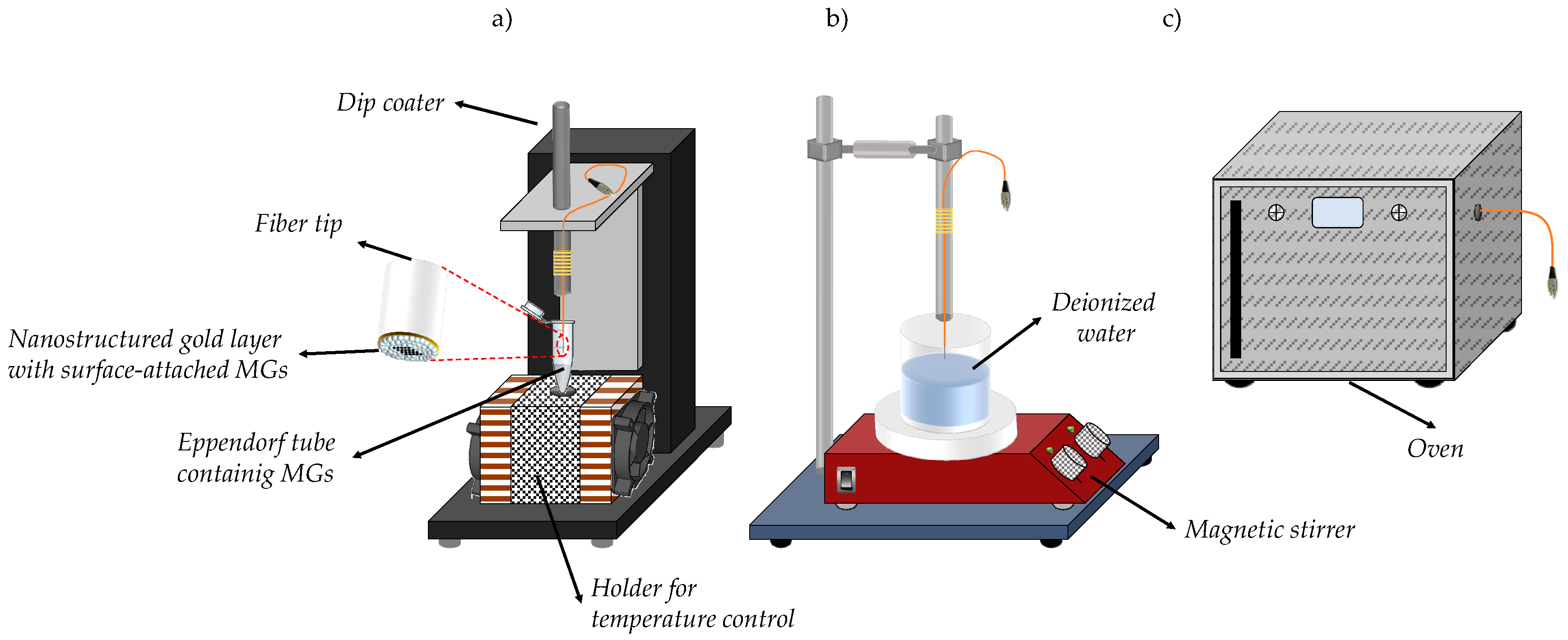
2.4. The Dip Coating Technique

The MGs coating procedure for the LOF probes is schematically shown in Figure 1: it consists of 4 main step: (i) dipping: by means of a dip coater (KSV NIMA KN4001, Biolin Scientific Oy, Espoo, Finland) the optical fiber probes are dipped into a 1.5 mL centrifuge tube containing a 500 µL aliquot of MGs solution at 5% with pH = 3. During the dipping phase, the temperature of MGs dispersion was kept at 10 °C by using a customized metallic holder heated by Peltier cells [8]. The speed and the duration of the dipping phase depend on the specific experiment carried out (details in the results section); (ii) first drying: after dipping, the fibers are taken out from the MGs solution and dried. Temperature and duration depend on the specific experiment carried out (details in the results section); (iii) rinsing: once dried, the optical fibers are immersed in a deionized water bath under magnetic stirring in order to ensure breaking up of potential multilayers and their removal from the tip surface. Temperature and duration are varied in our experiments carried out (details in the results section); (iv) second drying: after rinsing, the probes are dried again. Temperature and duration depend on the specific experiment (details in the results section).

2.5. Optical Characterization

The reflection spectra of the fabricated probes were measured by using an optical setup described in [8]. Briefly, the fiber probes are illuminated by a broadband optical source (NKT SuperK COMPACT, NKT Photonics, Birkerød, Denmarck) and an optical spectrum analyzer (Ando AQ 6715C, Yokogawa Electric Corporation, Tokyo, Japan) measures the reflected light thanks to a 2 × 2 directional coupler. Another spectrum analyzer measures the source light transmitted through the coupler. The reflectance spectrum is obtained by normalizing the sample spectrum with that of the source (taking also into account the transfer function of the coupler). Further details can be found in ref. [8].

2.6. Morphological Analysis

Morphological characterizations of the MGs film are directly performed onto the optical fibers tip by using the Atomic Force Microscope (AFM) (Agilent Technologies 5420, Agilent Technologies, Santa Clara, CA, USA) Specifically, AFM images are obtained by scanning the optical fiber tip in tapping mode in order to avoid damage of the polymeric film. The scanning of the fiber tip is achieved by using a customized holder that keeps the fiber in the right position [8]. The holder is essentially composed by an aluminum block where some grooves for the fibers are made by mechanical milling. A magnetic clamp lock the fibers vertically under the AFM scanner tip in such grooves. All the measurements were carried out with the MGs in the dry state. The raw data collected by the AFM are successively processed with the Pico Image software (Keysight Technologies, Santa Rosa, CA, USA).

3. Results and Discussion

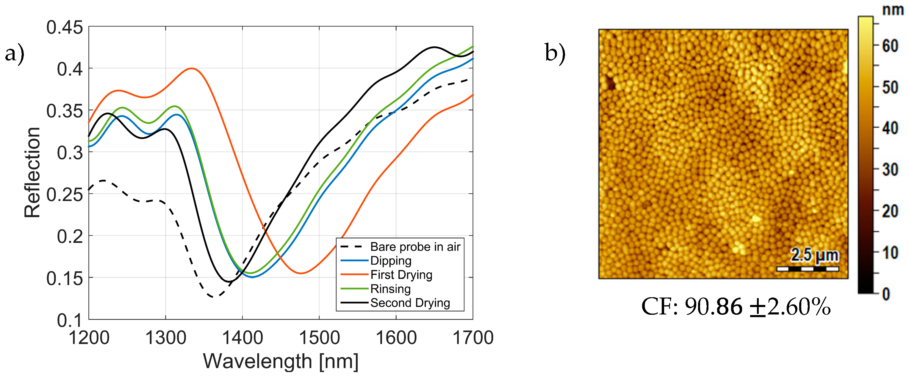
3.1. Optical Monitoring of the Fabrication Process

We started our analysis by monitoring the reflection spectra of the LOF probes in all the deposition steps used in our previous procedure [11]. Such a procedure, customized to work on the optical fiber tip, was similar to that typically used for depositing MGs on planar substrates [21,22]. The details of the fabrication path, including time and temperature of all the steps previously described in Section 2.4, are summarized in Table 1.
Figure 2a shows the reflection spectra of the LOF probe measured at the end of the different fabrication steps previously described in Section 2.3. Before the MGs deposition, the reflection spectrum of the LOF probe in air (dashed black curve) presents a dip centered at 1363 nm with a FWHM of 85 nm. The reflection dip is due to the excitation of a LSPR [8,9,10,11,12].
When the probe is immersed in the MGs solution, the resonance (and thus the reflection dip) undergoes a red shift of ~54 nm (solid blue curve), coherently with an increase of the plasmonic mode equivalent refractive index [23]. Once the probe is extracted from the MGs solution, the resonant dip undergoes a further red shift of ~58 nm (solid orange curve), i.e., ~112 nm with respect to the initial spectrum pertaining to bare LOF probe. The strong red shift observed in response to a bulk refractive index decrease (from buffer solution to air) is principally due to the presence of a dried MGs multilayer (whose refractive index is about 1.47) attached onto the gold nanostructure. During the rinsing step, the resonant dip shifts back to lower wavelengths (coherently with the drying of the surface attached MGs), stabilizing at 1411 nm (green curve), i.e., ~6 nm lower with respect to the spectrum pertaining to the previous dipping step. This difference could be explained with the detachment of MGs which were not strongly adsorbed onto the gold substrate. Finally, after the second drying step, the resonant dip is subjected to a further blue-shift of ~30 nm (solid black curve). These data confirm that the MGs detached from the fiber tip surface during the rinsing step. The opposite direction of the wavelength shift with respect to the first drying step can be explained by considering that, in this case, the attached MGs give rise to a monolayer whose thickness is not thick enough to ‘mask’ the effect of the bulk medium. Overall, at the end of the entire process, the reflection spectrum is shifted by ~17 nm with respect to the bare LOF probe one.
At this stage, we carried out a morphological characterization of the MGs film realized onto the fiber tip. Without loss of generality, we scanned an unpatterned area of 10 × 10 μm close to the nanostructure realized in correspondence of the fiber core. The morphological analysis has been carried out only outside of the fiber core area, because the presence of the nanostructure makes difficult to evaluate the CF. However, as already demonstrated in our previous studies [8,11,12] the pattern does not alter the distribution of the MGs, which are still conformally deposited onto the gold nanostructure. The AFM image shown in Figure 2b confirms the creation of a uniform and compact MGs film (with an average height lower than 40 nm, compatible with the formation of a single layer [11]), characterized by a CF higher than 90%. The CF is defined as the ratio between the portion of substrate occupied by MGs and the whole substrate area; it is calculated by processing the AFM images, according to the same procedure described in our previous work [11]. Also, repeatability tests on the CF calculation have been carried out by using other 4 fibers, so that CF and the correspondent uncertainty have been evaluated as average and standard deviation among 5 probes. We remark that repeatability studies, over 5 samples, for the correct CF evaluation have been carried out for all the tests described in the rest of this work.
Figure 3 shows the evolution of the resonance wavelength (i.e., the wavelength corresponding to the reflection minimum) as a function of time during the dipping (Figure 3a), first drying (Figure 3b), rinsing (Figure 3c) and second drying (Figure 3d) step, respectively. Spectra acquisition interval was set to 1 min. For better reading the data, only the wavelength shifts pertaining to the first 20 min of each step are shown.
Results essentially demonstrate that the dynamics associated to each fabrication step vanish in a time range significantly lower than that considered in the previous procedure. For estimating the extinction time of each dynamic, the wavelength shifts data were fitted with an exponential curve such as y = a + b e−t/τ. This allow us to find the time constants τ, and more specifically to define the interval (equal to 10 × τ) required for the single fabrication step to reach the steady state condition. Consequently, the duration of the dipping phase can be reduced down to ~1 min; while the first drying step takes about 6.5 min to be completed. Furthermore, the rinsing step dynamics is going down after ~2 min, while a time interval of 1.5 min is enough for completing the second drying step. It is interesting to notice that the second drying dynamic takes a time interval that is about 4 times smaller than that of the first one, because of the smaller amount of MGs attached on the fiber probe surface.
The formation of the MGs layer in the solution cannot be correctly monitored just from the optical point of view (i.e., by monitoring only the reflection spectrum changes as a function of time). This is because when the MGs are swollen in the wet state, their refractive index basically corresponds to that of the liquid bulk solution in which they are immersed. For this reason, in the following sections, we also carry out a careful AFM morphological analysis for studying the influence that each fabrication step has on the characteristics of the MGs film created onto the fiber tip. The MGs layer achieved with the previous procedure shown in Figure 2b represents the benchmark for comparability purposes.

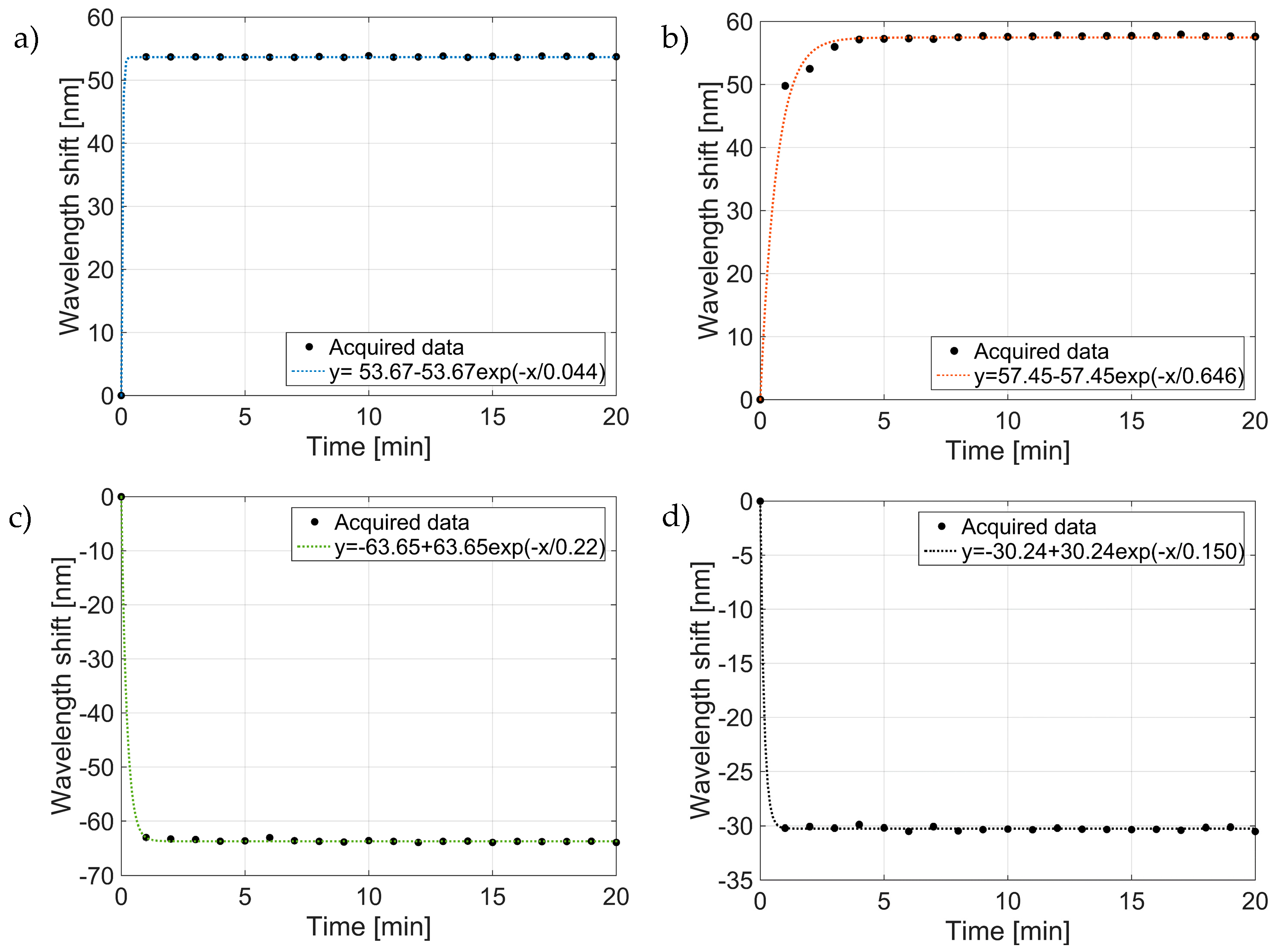
3.2. Study on the Dipping Step

We fabricated several probes by exploiting the previous procedure with the exception of the immersion speeds (details are summarized in Table 2). Specifically, 3 probes (i.e., the replica of the same LOF device) were dipped in the same MGs solution (pH 3, 10 °C) but with immersion speeds of 5, 100 and 200 mm/min. The speeds of 5 and 200 mm/min represent the minimum and the maximum value that it is possible to set with the dip coater. The immersion depth (2.5 mm) is the same for all the tests, so that the speeds of 5, 100 and 200 mm/min correspond to dipping time interval of 1, 0.05 and 0.025 min, respectively. The dipping time also includes the fiber extraction step. As mentioned before, both the rinsing and drying steps are carried out according to the previous procedure [11].
Figure 4 shows the AFM images of the fiber tips of the fabricated samples. The relative CF evaluated at the end of the deposition procedure is reported in the same figures. The CFs are found to be larger than 90% in all the cases, with a standard deviation smaller than 5%. The data confirm that a dipping duration less than 1 min is enough for creating a compact and uniform MGs layer. However, in the cases of dipping speeds of 100 and 200 mm/min (Figure 4b,c), the quality of the MGs films appears slightly degraded due to the presence of some areas with a lower particle density, probably due to a too fast dipping speed. On the other hand, with the dipping procedure of 5 mm/min (Figure 4a), no substantial differences among the MGs film properties are found in terms of compactness and uniformity degree if compared with the benchmark in Figure 2b. In the wake of this consideration, for the following tests, we opted for a dipping time of 1 min.

3.3. Study on the Drying Steps

After dipping, once the fiber probe is taken out from the MGs solution, it is necessary to dry the sample before the next rising step. As the MGs are sensitive to temperature, it is important to monitor the drying conditions (time and temperature). In our previous procedure, this step was particularly time consuming since the drying procedure was accomplished by means of an oven for 1 h at 45 °C. Analogously, after the rinsing step the MGs film is allowed to dry once again for 2 h at 30 °C in an oven before the optrode can be finally used for the specific application.
To understand to what extent it was necessary to control the drying conditions, we fabricated other probes carrying out the drying steps at room temperature (not controlled environment). In the wake of the results of Figure 4, discussed in the previous section, the dipping time was fixed at 1 min (with a speed of 5 mm/min). Coherently with the dynamic shown in Figure 3b,d, we investigated a drying duration of 10 min (for both the first and the second drying steps). Details on the deposition procedure are summarized in Table 3. The AFM image of the achieved MGs film (at the end of the whole deposition procedure) is shown in Figure 5.
From a visual comparison between the film in Figure 5 and the benchmark in Figure 2b, it is clear that 10 min are enough to ensure the correct drying of the MGs, and the consequent formation of a compact MGs monolayer. This aspect is confirmed by the value of the CF (also in this case evaluated as average among 5 probes fabricated with the same procedure) which is higher than 90%. This result confirms that it is possible to significantly reduce the duration of both the first and the second drying steps without using controlled temperature environment.

3.4. Study on the Rinsing Step

The rinsing step is necessary for removing the excess MGs particles which are not correctly deposited onto the fiber tip surface, thus causing the possible formation of a multilayer. To this end, the probes are immersed in water under magnetic stirring. Previous studies have demonstrated that the water temperature does not affect the MGs detachment from the substrate [24,25]. Following a similar approach exploited before (details in Table 4), we fabricated other probes with a rinsing time of 10 min, corresponding to the 1.4% of the duration considered in the previous procedure (12 h). Note that the new rinsing time is sufficiently larger with respect to the extinction time of 10τ extrapolated from the dynamic shown in Figure 3c.
The AFM image shown in Figure 6 demonstrates that 10 min are enough to break up and remove the MGs agglomerates, providing a compact and uniform monolayer with a CF of about 91%. From a one to one comparison between Table 1 and Table 4 (and the relative AFM images shown in Figure 2b and Figure 6) it results that the optimized procedure allows to achieve a saving of 98.3%, 83.3%, 98.6% and 91.6% of the time needed for the dipping, first drying, rinsing and second drying steps respectively. Moreover, the new procedure does not require the use of the oven (and related temperature and humidity controlled conditions) for the dying steps.

3.5. Remarks on the Optrode Performances

To understand if the time reduction affects the device performances, we carried out a thermal characterization on the optrode fabricated with the new optimized procedure whose details are resumed in Table 4. Details on the temperature measurements are reported in [11]. Figure 7 shows the evolution of the resonant wavelength (corresponding to the reflectance dip) as a function of temperature in the range 6–49 °C at pH 4.
These results are quantitatively in line with those pertaining to the same optrodes fabricated with our previous procedure, which were discussed in [11].

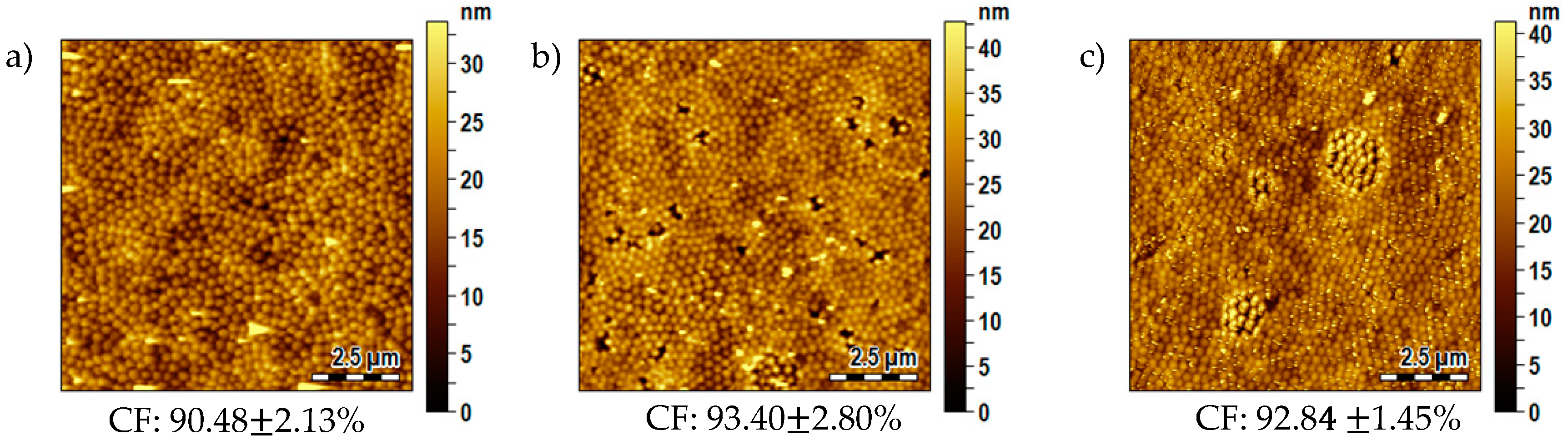
3.6. Influence of the Substrate Typology

The results discussed so far referred to the integration of MGs layers onto the gold coated (patterned) optical fiber tip. To evaluate the generality of our finding, we studied also the case in which the MGs film is created directly onto the bare fiber tip, i.e., onto the silica glass. In this regard, it is important to underline that, in the case of a gold surface, the MGs-Au bond is favored by the Van der Waals interactions, and by the coordination between nitrogen and oxygen atoms [25,26,27]. Vice versa, the MGs-glass (SiO2) interactions are weak and strongly depends from the solution pH and ionization state of silanol groups on glass surface [28]. For these reasons, to favor the MGs attachment onto glass surface, it is necessary to treat the bare optical fiber with silane and promote the covalent coupling of the MGs on the glass surface. To this end, after cutting, the fiber tip underwent a silanization process, and a new set of PNIPAm-co-MAAc MGs was synthesized as previously mentioned in Section 2.1. Details on the entire procedure are provided in Section 2.3.
For depositing the MGs film, we exploited the optimized procedure whose details are resumed in Table 4. The reflection spectrum of the silanized bare fiber is essentially flat (with a value of about 4%) simply because the silanization procedure does not affect the bare fiber behavior from the optical point of view. In other words, the glass surface modification is only ‘chemical’ and, obviously, no resonant effect are generated. Also in this case, the morphological analysis was carried out at the end of the second drying step. Figure 8 confirms the creation of a uniform and homogeneous layer of MGs with a CF of ~90%. Although not directly evaluable by means of optical characterization, the robustness of this optrode (in which the MGs are attached directly onto the uncoated fiber) is guaranteed by the silanization procedure, which allows to promote a covalent anchoring of the MGs on the glass surface. Moreover, there is no evidence to suggest that the MGs move or migrate from the fiber surface during rinsing under stirring, thus indicating a very strong MGs-substrate bond.

4. Conclusions

In conclusion, we have proposed an optimized dip coating procedure for creating a uniform MGs layer onto the tip of optical fibers. This study complements our previous work in which we determined the optimum MGs dispersion parameters (solution temperature, pH and particle concentration) needed for achieving a compact MGs layer [11]. Here, we have essentially monitored the duration of the deposition steps and recognized that all of them can be shortened without affecting the quality of the MGs layer created on the fiber tip. Specifically, we have demonstrated that it possible to obtain MGs layers with coverage factors larger than 90% in about 30 min, which represents a significant step ahead with respect to the previous procedure, which was about 30 times longer. Our procedure is general and it has been successfully validated on both gold coated and uncoated optical fiber tips. Overall, our studies represent a solid foundation for developing advanced LOF probes integrated with MGs, with high fabrication throughput (the probe production can be also parallelized), and thus ready to be exploited at the industrial application level.

Author Contributions

L.S., M.G., A.M., collected and analyzed the data; A.A. and M.R. synthesized the MGs and silanized the optical fibers. L.S., M.G. and A.A. deposited the MGs films; E.B., V.L.F. and A.M. fabricated and characterized the optical fiber devices; A.R. conceived the idea and designed the experiments; A.C. supervised the project; all authors contributed to the writing of the manuscript.

Funding

This research received no external funding.

Acknowledgments

We thank Sofia Principe and Federica Gambino for their support during the MGs deposition onto the bare optical fiber.

Conflicts of Interest

The authors declare no conflict of interest.

References

  1. Cusano, A.; Consales, M.; Crescitelli, A.; Ricciardi, A. Lab-on-Fiber Technology; Springer: New York, NY, USA, 2015; Volume 56. [Google Scholar]
  2. Consales, M.; Ricciardi, A.; Crescitelli, A.; Esposito, E.; Cutolo, A.; Cusano, A. Lab-on-Fiber Technology: Toward Multifunctional Optical Nanoprobes. ACS Nano 2012, 6, 3163–3170. [Google Scholar] [CrossRef] [PubMed]
  3. Ricciardi, A.; Consoles, M.; Quero, G.; Crescitelli, A.; Esposito, E.; Cusano, A. Versatile Optical Fiber Nanoprobes: From Plasmonic Biosensors to Polarization-Sensitive Devices. ACS Photonics 2014, 1, 69–78. [Google Scholar] [CrossRef]
  4. Ricciardi, A.; Crescitelli, A.; Vaiano, P.; Quero, G.; Consales, M.; Pisco, M.; Esposito, E.; Cusano, A. Lab-on-fiber technology: A new vision for chemical and biological sensing. Analyst 2015, 140, 8068–8079. [Google Scholar] [CrossRef] [PubMed]
  5. Vaiano, P.; Carotenuto, B.; Pisco, M.; Ricciardi, A.; Quero, G.; Consales, M.; Crescitelli, A.; Esposito, E.; Cusano, A. Lab on Fiber Technology for biological sensing applications. Laser Photonics Rev. 2016, 10, 922–961. [Google Scholar] [CrossRef]
  6. Kostovski, G.; Stoddart, P.R.; Mitchell, A. The Optical Fiber Tip: An Inherently Light-Coupled Microscopic Platform for Micro- and Nanotechnologies. Adv. Mater. 2014, 26, 3798–3820. [Google Scholar] [CrossRef] [PubMed]
  7. Carotenuto, B.; Micco, A.; Ricciardi, A.; Amorizzo, E.; Mercieri, M.; Cutolo, A.; Cusano, A. Optical Guidance Systems for Epidural Space Identification. IEEE J. Sel. Top. Quantum Electron. 2016, 23. [Google Scholar] [CrossRef]
  8. Aliberti, A.; Ricciardi, A.; Giaquinto, M.; Micco, A.; Bobeico, E.; La Ferrara, V.; Ruvo, M.; Cutolo, A.; Cusano, A. Microgel assisted Lab-on-Fiber Optrode. Sci. Rep. 2017. [Google Scholar] [CrossRef] [PubMed]
  9. Giaquinto, M.; Micco, A.; Aliberti, A.; Ricciardi, A.; Ruvo, M.; Cutolo, A.; Cusano, A. Microgel Photonics and Lab on Fiber Technology for Advanced Label Free Fiber Optic Nanoprobes. Proc. SPIE 2016. [Google Scholar] [CrossRef]
  10. Ricciardi, A.; Aliberti, A.; Giaquinto, M.; Micco, A.; Cusano, A. Microgel Photonics: A Breathing Cavity onto OPTICAL FIBRE TIP. In Proceedings of the 24th International Conference on Optical Fibre Sensors, Curitiba, Brazil, 28 September–2 October 2015; SPIE: Bellingham, WA, USA, 2015. [Google Scholar]
  11. Giaquinto, M.; Micco, A.; Aliberti, A.; Bobeico, E.; La Ferrara, V.; Menotti, R.; Ricciardi, A.; Cusano, A. Optimization Strategies for Responsivity Control of Microgel Assisted Lab-On-Fiber Optrodes. Sensors 2018, 18, 1119. [Google Scholar] [CrossRef] [PubMed]
  12. Giaquinto, M.; Ricciardi, A.; Aliberti, A.; Micco, A.; Bobeico, E.; Ruvo, M.; Cusano, A. Light-microgel interaction in resonant nanostructures. Sci. Rep. 2018, 8, 9331. [Google Scholar] [CrossRef] [PubMed]
  13. Pelton, R.; Hoare, T. Microgels and their synthesis: An introduction. In Microgel Suspensions: Fundamentals and Applications; Wiley: Hoboken, NJ, USA, 2011; pp. 1–32. [Google Scholar]
  14. Pelton, R. Temperature-sensitive aqueous microgels. Adv. Colloids Interface Sci. 2000, 85, 1–33. [Google Scholar] [CrossRef]
  15. Plamper, F.A.; Richtering, W. Functional Microgels and Microgel Systems. Accounts Chem. Res. 2017, 50, 131–140. [Google Scholar] [CrossRef] [PubMed]
  16. Wei, M.L.; Gao, Y.F.; Li, X.; Serpe, M.J. Stimuli-responsive polymers and their applications. Polym. Chem. 2017, 8, 127–143. [Google Scholar] [CrossRef] [Green Version]
  17. Islam, M.R.; Ahiabu, A.; Li, X.; Serpe, M.J. Poly-(N-isopropylacrylamide) Microgel-Based Optical Devices for Sensing and Biosensing. Sensors 2014, 14, 8984–8995. [Google Scholar] [CrossRef] [PubMed]
  18. Islam, M.R.; Irvine, J.; Serpe, M.J. Photothermally induced optical property changes of poly-(N-isopropylacrylamide) microgel-based etalons. ACS Appl. Mater. Interfaces 2015, 7, 24370–24376. [Google Scholar] [CrossRef] [PubMed]
  19. Dhanya, S.; Bahadur, D.; Kundu, G.C.; Srivastava, R. Maleic acid incorporated poly-(N-isopropylacrylamide) polymer nanogels for dual-responsive delivery of doxorubicin hydrochloride. Eur. Polym. J. 2013, 49, 22–32. [Google Scholar] [CrossRef]
  20. Micco, A.; Ricciardi, A.; Pisco, M.; La Ferrara, V.; Cusano, A. Optical fiber tip templating using direct focused ion beam milling. Sci. Rep. 2015, 5, 15935. [Google Scholar] [CrossRef] [PubMed] [Green Version]
  21. Schmidt, S.; Hellweg, T.; von Klitzing, R. Packing density control in P (NIPAM-co-AAc) microgel monolayers: Effect of surface charge, pH, and preparation technique. Langmuir 2008, 24, 12595–12602. [Google Scholar] [CrossRef] [PubMed]
  22. Nerapusri, V.; Keddie, J.L.; Vincent, B.; Bushnak, I.A. Swelling and deswelling of adsorbed microgel monolayers triggered by changes in temperature, pH, and electrolyte concentration. Langmuir 2006, 22, 5036–5041. [Google Scholar] [CrossRef] [PubMed]
  23. Spackova, B.; Wrobel, P.; Bockova, M.; Homola, J. Optical Biosensors Based on Plasmonic Nanostructures: A Review. Proc. IEEE 2016, 104, 2380–2408. [Google Scholar] [CrossRef]
  24. Serpe, M.J.; Jones, C.D.; Lyon, L.A. Layer-by-layer deposition of thermoresponsive microgel thin films. Langmuir 2003, 19, 8759–8764. [Google Scholar] [CrossRef]
  25. Sorrell, C.D.; Carter, M.C.; Serpe, M.J. A “paint-on” protocol for the facile assembly of uniform microgel coatings for color tunable etalon fabrication. ACS Appl. Mater. Interfaces 2011, 3, 1140–1147. [Google Scholar] [CrossRef] [PubMed]
  26. Lu, Y.; Drechsler, M. Charge-induced self-assembly of 2-dimensional thermosensitive microgel particle patterns. Langmuir 2009, 25, 13100–13105. [Google Scholar] [CrossRef] [PubMed]
  27. Iori, F.; Corni, S.; Di Felice, R. Unraveling the interaction between histidine side chain and the Au(111) surface: A DFT study. J. Phys. Chem. C 2008, 112, 13540–13545. [Google Scholar] [CrossRef]
  28. Burmistrova, A.; Steitz, R.; von Klitzing, R. Temperature Response of PNIPAM Derivatives at Planar Surfaces: Comparison between Polyelectrolyte Multilayers and Adsorbed Microgels. Chemphyschem 2010, 11, 3571–3579. [Google Scholar] [CrossRef] [PubMed]
Figure 1. Schematic view of the dip coating procedure. (a) Dipping, (b) rinsing and (c) drying steps. The inset in (a) shows a schematic of the LOF probe integrated with MGs.
Fibers 06 00072 g001
Figure 2. Characterization of the MGs film deposited following the previous procedure onto the goad coated optical fiber tip. (a) Reflection spectra of the LOF probes measured at the end of each fabrication step. (b) AFM characterization of the realized MGs film at the end of the entire procedure, pertaining to an unpatterned area of 10 × 10 μm close to the nanostructure.
Fibers 06 00072 g002
Figure 3. Resonant wavelength shifts measured during the fabrication steps of the previous deposition procedure. (a) Dipping step, (b) first drying step, (c) rinsing step, (d) second drying step. The dotted curves are the exponential fit of the acquired data.
Fibers 06 00072 g003
Figure 4. AFM images of the MGs film realized onto the gold coated fiber tip with different dipping time and speed. (a) 1 min (at 5 mm/min), (b) 0.05 min (at 100 mm/min), (c) 0.025 min (at 200 mm/min).
Fibers 06 00072 g004
Figure 5. AFM image of the MGs film realized onto the gold coated fiber tip with a dipping time and drying steps reduced respectively to 1 min and 10 min, and rinsing time of 12 h.
Fibers 06 00072 g005
Figure 6. AFM image of the MGs film realized onto the gold coated fiber tip with the optimized procedure (dipping: 1 min, drying: 10 min, rinsing: 10 min).
Fibers 06 00072 g006
Figure 7. Resonant wavelength shift as function of solution temperature at pH 4 for the optrode fabricated with the new optimized procedure. The error bars represent one standard deviation evaluated on 5 acquisitions. The dashed lines were obtained with a smoothing spline fitting.
Fibers 06 00072 g007
Figure 8. AFM image of the MGs film realized onto the silanized glass fiber tip, following the optimized procedure.
Fibers 06 00072 g008
Table 1. Fabrication step details of the previous deposition procedure.
Deposition StepTimeTemperature
Dipping1 h 110 °C
First drying1 h45 °C
Rinsing12 hroom
Second Drying2 h30 °C
1 dipping speed 5 mm/min.
Table 2. Fabrication step details of the deposition procedure with the optimized dipping step.
Deposition StepTime Temperature
Dipping1, 0.05, 0.025 min 110 °C
First drying1 h45 °C
Rinsing12 hroom
Second Drying2 h30 °C
1 corresponding to dipping speeds of 5, 100 and 200 mm/min respectively.
Table 3. Fabrication step details of the deposition procedure with optimized drying steps.
Deposition StepTimeTemperature
Dipping1 min 110 °C
First drying10 minroom
Rinsing12 hroom
Second Drying10 minroom
1 dipping speed 5 mm/min.
Table 4. Fabrication step details of the optimized deposition procedure.
Deposition StepTimeTemperature
Dipping1 min 110 °C
First drying10 minroom
Rinsing10 minroom
Second Drying10 minroom
1 dipping speed 5 mm/min.

