Gas-Liquid Hollow Fiber Membrane Contactors for Different Applications

1
A.V. Topchiev Institute of Petrochemical Synthesis, Russian Academy of Sciences, Moscow 119991, Russia
2
Institute of Physical Organic Chemistry, National Academy of Sciences of Belarus, Minsk 220072, Belarus
*
Author to whom correspondence should be addressed.
Fibers 2018, 6(4), 76; https://0-doi-org.brum.beds.ac.uk/10.3390/fib6040076
Submission received: 14 September 2018
/
Revised: 1 October 2018
/
Accepted: 2 October 2018
/
Published: 10 October 2018
(This article belongs to the Special Issue Polymer Hollow Fiber Membrane)
Abstract
:Gas-liquid membrane contactors that were based on hollow fiber membranes are the example of highly effective hybrid separation processes in the field of membrane technology. Membranes provide a fixed and well-determined interface for gas/liquid mass transfer without dispensing one phase into another while their structure (hollow fiber) offers very large surface area per apparatus volume resulted in the compactness and modularity of separation equipment. In many cases, stated benefits are complemented with high separation selectivity typical for absorption technology. Since hollow fiber membrane contactors are agreed to be one of the most perspective methods for CO2 capture technologies, the major reviews are devoted to research activities within this field. This review is focused on the research works carried out so far on the applications of membrane contactors for other gas-liquid separation tasks, such as water deoxygenation/ozonation, air humidity control, ethylene/ethane separation, etc. A wide range of materials, membranes, and liquid solvents for membrane contactor processes are considered. Special attention is given to current studies on the capture of acid gases (H2S, SO2) from different mixtures. The examples of pilot-scale and semi-industrial implementation of membrane contactors are given.
1. Introduction
The proposal of Mahon and the group at Dow Chemical [1] to use hollow-fiber membranes as a separation device and their development represents one of the major events in membrane technology. Since then synthetic polymeric hollow-fiber membranes have advanced to play a key role in separation technologies. When compared to the flat-sheet membrane, hollow-fiber configuration has the following advantages: (1) a much larger membrane area per unit volume of membrane module resulting in a higher overall productivity; (2) high self-mechanical support, and (3) good flexibility and easy handling during module fabrication, membrane reparation, and system operation [2,3]. The typical example of hollow fiber membrane made from polysulfone is given in Figure 1.
The benefits listed above are efficiently implemented in hollow fiber gas-liquid membrane contactors. Basically, contactors are membrane modules for transport of component between gas and liquid phases. In this case, membranes play the role of interface preventing direct mixing and the dispersion of phases.
In the following review, we tried to summarize extensively studied key separation processes, which can benefit the most from the employment of hollow fiber membrane contactors. The review data are presented in a tabular form providing comprehensive information on the types of hollow fibers used, the principal parameters of gas-liquid membrane contactors, and the experimental conditions in membrane contactor processes. The authors hope that the detailed information on the properties of hollow fiber membranes (geometrical and pore sizes, porosity) and the membrane manufacturers will be of advantage for researchers dealing with general issues of fabrication and the employment of synthetic fibers.
2. Basic Principles, Advantages, and Disadvantages of Hollow Fiber Membrane Contactors
A membrane contactor is a device that is designed to implement a separation or chemical transformation process, employing a membrane as an interface between two phases. While the key function of a membrane is separation by means of selective mass transfer, the membrane contactors do not require membrane selectivity. Generally, a membrane in a gas-liquid contactor is used exclusively as an interface between the gas and liquid phases, providing their efficient contact without direct mixing due to, among other things, high surface area [4,5,6]. The selective properties of membrane contactor are provided by a difference between solubility of the components in the liquid phase used. Therefore, most gas-liquid membrane contactors employ porous membranes that provide high mass transfer properties. However, some tasks necessitate the employment of composite membranes or asymmetric membranes with a thin nonporous polymer layer, e.g., in the case of high-pressure processes [7].
Ideally, a porous hydrophobic membrane excludes the penetration of liquid (particularly, aqueous) phase into the pores; the whole pore volume is filled with gas, and the mass transfer resistance from the membrane side is minimum. Karoor & Sirkar [8] were the first to present the benefits of non-wetted mode (when the membrane pores are filled with gas). Figure 2 shows the interface between the gas and liquid phases in a hydrophobic symmetrical porous membrane.
In this case, the contact area can be defined as the area of membrane pore mouths, and the operating pressure in the system has to be thoroughly controlled in order to avoid the intermixing of phases. Particularly, the aqueous phase pressure should be equal to or exceed that of the gas phase to completely exclude the possibility of gas bubbles dispersion in the liquid and, therefore, to avoid the undesirable phase mixing mode [9]. On the other hand, the interface area can be defined precisely only if the penetration of aqueous phase into membrane pores is completely excluded. The phenomenon of pore filling with liquid—‘pore wetting’—can derive from exceedingly high pressure from the liquid side, which, at worst, results in transmembrane flux appearance, and, consequently, a drastic decrease in overall gas transport properties. In the case when the liquid layer is immobilized in the pore space, its mass transfer resistance is too high, and the mass-transfer through the membrane becomes a limiting step of the process. As shown in [9,10,11,12], even partial pore filling with liquid leads to a sharp increase in the diffusional resistance in membrane pores, resulting in a drastic decline of membrane gas transport properties. According to Wang et al. [11], 5% wetting of membrane pores leads to a 20% decrease in the overall mass transfer coefficient. On the other hand, as shown in [13], even 2% wetting of membrane pores increases membrane resistance by up to 6%. In some cases, the membrane resistance contribution can reach 90% value [14].
In fact, the hydrophobicity of membrane material does not provide the non-wetted mode if the liquid phase pressure exceeds a critical level (also referred to as breakthrough pressure) [12,15,16]. A breakthrough pressure for each membrane depends on the surface tension of the liquid used as well as on its contact angle value at given operating conditions. The pressure can be quantitively estimated according to Laplace’s equation:
where ΔP—critical breakthrough transmembrane pressure, rp,max—maximum pore radius in the cylindrical approximation, σ—liquid surface tension, and θ—contact angle value.
In the case of asymmetrical membranes, the pore size in which decreases gradually when passing from one membrane surface to another, two phases can be brought in contact without dispersion even when operating pressure exceeds the breakthrough pressure on the membrane side with larger pores. Since breakthrough pressure is inversely proportional to membrane pore size, partial wetting can take place only from the side of larger pores, whereas the smaller pores remain resistant to liquid penetration. In this case, the gas-liquid interface appears inside the pore space (see Figure 3a).
Another approach aimed to increase the operating pressure of the liquid phase in a membrane contactor is to employ composite membranes with a thin non-porous layer on the porous support. This layer prevents the penetration of the liquid phase into membrane pore space (see Figure 3b) [17,18,19]. A non-porous layer on the porous membrane surface provides a way to extend the range of operating pressures. However, such a layer should be highly permeable; otherwise, membrane resistance to the mass transfer process will increase.
Gas-liquid membrane contactors may be employed for absorption of the desired component in a liquid absorbent (see Figure 4a), as well as for reverse process—desorption from the liquid phase (see Figure 4b). Furthermore, membrane contactors possess a number of essential properties due to the hollow fiber membrane configuration, thus being promising contact devices.
As can be seen from Figure 4a,b, the ideal case of membrane contactor operation provides a way to implement both absorption and desorption process at the clearly defined gas-liquid membrane interface. This means that the area of contact and mass transfer remains constant, and all of the equipment operates with equal productivity, even when the process conditions or the liquid properties are changed.
As noted above, hollow fiber membranes provide large surface area per apparatus volume (up to 10,000 m2/m3), thus making the equipment compact (with small dimensions and weight) [4,5]. As shown in [20], the dimensions and weight of the membrane contactor can be decreased by 72% and 66%, respectively, as compared to conventional absorption columns. Furthermore, theoretical estimations indicate [21] that the dimensions of an absorber can be reduced to 10 times when replaced with a membrane contactor.
It is important to emphasize that a large phase contact area is the key factor providing high efficiency of hollow fiber membrane contactors compared to conventional techniques and equipment (e.g., packed columns). Furthermore, the mass transfer coefficient values for membrane contactors and packed columns are usually comparable. It was proved experimentally that the overall mass transfer coefficient of a membrane contactor could be increased by 40–50% [22], which corresponds to a decrease in absorber dimensions by the same 40–50%.
An important advantage of membrane contactors is the absence of dispersion between two phases. Therefore, there is no need to separate the phases in output and also no droplet carry-out or foaming in liquid phase; gas and liquid flows can be controlled independently within the wide range of process rates [6].
Like all membrane processes, membrane contactors provide operating flexibility and scale-up simplicity due to the modular nature. They do not have any moving parts or elements [23] and, in general, operate with low pressure drops (not more than 1.2 bar [24]).
However, membrane contactors have a number of disadvantages. First of all, the membrane itself contributes to the overall mass transfer resistance. Other disadvantages are the follows: decreasing with time mass transport properties as a result of wetting in porous hollow fiber membrane [11,25] or physical aging of top layer material in composite membrane [18,26]; process sensitivity to impurities in gas mixture [27,28] or liquid phase [29], which affect chemical resistance of a membrane material; and, limited temperature and pressure range for polymeric hollow fiber membranes [25].
3. Design of Membrane Contactors
3.1. Lab-Scale and Pilot Membrane Contactors
The development of hollow fiber membrane contactors began with conventional ‘shell-and-tube’ modules, with hollow fiber membranes playing the role of tubes. In this case, the contacting phases are brought into fiber lumen and shell side in a co-current or counter-current flow regime [30,31,32]. In the configuration considered initially, the liquid phase was brought into fiber lumen to provide equal distribution of liquid phase and to achieve operation of all fibers in the contactor. However, it caused large pressure drop due to high hydraulic resistance with a decreased diameter of hollow fibers. Consequently, it significantly restrained the possibility of increasing liquid phase flow in these devices and the development of compact industrial contactors [30].
In the case when water is brought into the shell side, the hydraulic resistance of the module decreases, thus decreasing the liquid pressure drop. As shown by Wang and Cussler [31], if the liquid in the shell side flows normally to the axis of the fibers (and gas is brought inside the fibers), then the mass transfer coefficient increases significantly. From this perspective, transverse-flow modules were designed and constructed [6], and the most of modern gas-liquid contactors originate from these modules.
The transverse-flow was investigated by Bhaumik et al. [33] for the development of a device based on a mat of hollow fibers wound around the central porous tube (liquid dispenser). The authors proved the efficiency of these systems for CO2 absorption in water.
TNO Company (Den Haag, The Netherlands) was the first who patented a cubical module containing fibers aligned in a certain order providing good flow distribution [34]. These systems are notable for high mass transfer coefficients, low-pressure drop, and scale-up simplicity. Furthermore, successful pilot-scale experiments were performed for various fields of application [35]. TNO also patented a novel type of membrane module providing gas flows operation at high pressures [36]. The module that was based on hollow fibers in a high-pressure shell is designed for absorption of different gases, such as CO2 and H2S for natural gas stripping or the purification of petrochemical flows.
3.2. Commercial Membrane Contactors
Memrbana-Charlotte Company (Charlotte, NC, USA, formerly a division of Celgard LLC, today a division of 3M) is a leading manufacturer of membrane contactors. It offers a line of membrane modules of various performance, designed for mass transfer tasks in gas-liquid systems. Figure 5 shows commercial membrane contactor Liqui-Сel® (Liqui-Cel™ Extra-Flow membrane contactor, 3M, Maplewood, MN, USA) [37].
Liqui-Сel® contactors are equipped with porous polypropylene membranes Celgard X50, which are supplied in a fiber mat form: parallel hollow fibers are connected to each other by a polymer thread (see down part of Figure 5). Such a configuration is designed to simplify packing of membranes into commercial Liqui-Cel® contactor housings. A membrane sheet is wound around the axial porous tube (liquid dispenser), and the membranes are parallel to the tube axis. A baffle, located in the middle of the axial tube and module, bisects the module and directs the liquid into fiber shell side in the first (left) compartment of the module. Further, the liquid, reaching the outer boundary of the fibers and passing through the gap between the baffle and the wall of the module housing, enters the second (right) compartment of the module and it moves perpendicular to the fibers in the direction of the axial tube through which it exits the apparatus. Consequently, transverse liquid flow (in relation to gas flow in the fiber lumen) is achieved in each compartment of the module [37]. Transverse-flow hollow fiber contactors possess the following advantages:
- liquid flows perpendicularly to the fibers, forming local turbulence and thus increasing the mass transfer coefficient in the liquid phase in fiber shell side; and,
- due to the equal distance between the fibers and to the baffle, a liquid flow channel in the fiber shell side minimizes.
These membrane modules were designed mostly for outgassing of water (to obtain ultra-pure water for electronics and energy industries), carbonation of beverages, etc. More detailed information on case studies can be found on the manufacturer website [38].
4. Membrane Materials for Hollow Fiber Membrane Contactors
Currently, a wide range of hollow fiber membranes is introduced to the market. The membranes differ in their morphology, transport properties, and separation mechanisms. All of the characteristics mentioned are mainly determined by membrane material properties and fabrication techniques. Generally, synthetic membranes comprise organic (polymeric) membranes and inorganic membranes, but the most of membrane contactors employ polymeric membranes. As mentioned above, membranes can be symmetrical (porous or non-porous, or dense) or asymmetrical, the latter possessing pore size gradient across membrane thickness, which can include thin non-porous layer on the membrane surface. Asymmetrical membranes can be fabricated from the same polymeric material or else from different polymeric materials—in the case of composite membranes.
Fabrication of porous membranes assumes that selection of main membrane polymer should be conditioned mainly by high chemical and thermal stability of the membrane. Porous polymeric hollow fiber membranes are fabricated by different techniques. For example, membranes from chemically stable PP or PTFE are prepared by melting extrusion, followed by stretching to form the pores. Fibers from the other polymers (PVDF, PSF, PEI, etc.) can be prepared with different non-solvent induced or temperature-induced phase separation techniques. Selection of efficient polymeric material should also consider its specific operating conditions and operational features of the membrane materials obtained. Table 1 lists main membrane materials used for the fabrication of hollow fiber membranes in membrane contactors.
5. Membrane Contactor Applications
5.1. Removal of Acid Components from Gas Mixtures
Perhaps the first place in the number of works devoted to hollow fiber membrane contactors is occupied by the acid gas removal: carbon and sulfur dioxides (CO2, SO2) and hydrogen sulfide (H2S) capture processes. These components are formed in a number of technological operations. For instance, CO2 and SO2 are formed in large quantities during the burning of fossil fuels and also during steel and cement production. The removal of these gases is very important from the ecological point of view, since CO2 is one of the key greenhouse gases, and SO2 emissions result in acid rain problems. In natural gas treatment processes, CO2 and H2S removal are crucial both economically and technologically, since H2S is extremely toxic and it also poisons catalysts used in some further natural gas treatment processes, while CO2 decreases its combustion heat. In addition, both CO2 and H2S corrode industrial equipment. The same factors determine the necessity of H2S and CO2 removal from the product of hydrogen or methane biomass fermentation—so-called biogas.
The conventional technique is the absorptive removal of acid components employing various absorption liquids. The principle of the technique is shown in Figure 6.
The main components of the system are devices for absorption and direct interaction between acid gases and selective absorbent (absorber) as well as the reverse process—desorption of acid gases and regeneration of absorbent (stripper). The devices are large metal-consuming columns with lots of contact elements. These devices are meant to be replaced with hollow fiber membrane contactors—more compact and cheap module systems.
5.1.1. Removal of CO2
Removal of CO2 from gaseous media is the most studied area in the field of hollow fiber contactors. Not only novel membrane materials and membranes are extensively developed, but also CO2-selective absorption liquids that are compatible with the fibers are under investigation. Process design for membrane contactors improves, while carbon dioxide removal is the object of numerous physical, chemical, and technological simulation studies. In terms of the present review, this aspect is not considered in details, since literature provides a number of special overviews [16,23,49]. Two review articles were published recently: one of them is focused on post-combustion carbon capture [50]. In another paper, we analyzed the recent research results considering development and fabrication of porous and composite hollow fiber membranes for contactors. The most popular solvents for carbon dioxide capture were also described, with a particular focus on the pilot tests of membrane contactors [51].
5.1.2. Removal of H2S
Table 2 provides a review of recent works on hydrogen sulfide removal. The key fields of application for membrane contactors are H2S odor control, H2S removal from natural gas, and biogas purification. The latter two research areas are the most extensively studied. Natural gas sweetening employs mostly hollow fiber membranes of various configurations made from perfluorinated polymers—PVDF [52], PTFE [53], poly(tetrafluoroethylene-co-perfluorinated alkyl vinyl ether) (PFA) [54], but there is also an example of employing PSF fibers [52]. This is determined mainly by the combination of two factors: (1) absorbents are alkaline agents in aqueous solution form (solutions of NaOH, K2CO3 [54], monoethanolamine (MEA), diethanolamine (DEA) [55], and methyldiethnolamine (MDEA) [52]) able to chemical bonding with H2S; in relation to the agents, hydrophobic fibers are relatively inert and are poorly wetted by them; (2) natural gas sweetening takes place at high pressures (approx. 50 bar), and thus absorbent breakthrough pressure values that are typical for perfluorinated fibers become important [55]. A feature of this approach is the fact that natural gas often includes CO2 also, and both acidic components have to be removed—the works mentioned above focus on this.
Researchers studying H2S removal from biogas employ not only hydrophobic porous hollow fibers (e.g., from PVDF [56,57]), but also non-porous fibers from PDMS. The works [48,58] should be noted where authors used a single PDMS hollow fiber having atypical large sizes (7.0 mm/9.0 mm) in immersion-type membrane contactor and achieved high H2S removal degrees with low methane loss. The result was achieved through a combination of hollow fiber operation and the employment of sulfur-oxidizing microorganisms in the liquid phase.
5.1.3. Removal of SO2
The only field comprising absorptive removal of SO2 in membrane contactors is the Flue-Gas Desulfurization (FGD) process (see Table 3). Researchers employ a number of membrane materials: PSF [62], PP [44,63], PVDF [64], and even ceramic hollow fiber membranes from aluminum oxide [56,57]. The latter were extensively studied by A. Irabien and co-authors: the researchers employed commercial modules containing 280 fibers for SO2 capture using organic solvent N,N-dimethylaniline [65,66]. The alternative absorbent used belongs to a novel generation of solvents—ionic liquid 1-ethyl-3-methylimidazolium ethyl sulfate [67,68]. As widely known, ionic liquids (ILs), which are organic salts with melting temperatures less than 100 °C [69,70], might also possess relatively high acid gas solubility and noticeable selectivity over other gases, and were already proposed for CO2 capture/stripping in membrane gas-liquid contactors [71,72] as an alternative to conventional solvents due to extremely low volatility, good thermal stability, lower heat duty at desorption stage as a result of physical bonding of CO2 molecules, low corrosiveness, and even biodegradability [73,74].
The works of the last five years in the field are mainly devoted to computational fluid dynamics (CFD) simulation of SO2 absorption in hollow fibers [63,75,76,77], while there are virtually no experimental works using the novel hollow fiber membranes.
The only published pilot-scale study of FGD process was performed in the early 00’s by TNO company, as mentioned in [78,79]. The authors declare that they implemented the PP-fibers based system with sodium bisulfite solution inside the fibers that allows for obtaining a SO2 recovery of over 95% at a capacity of 120 m3/h of SO2-containing flue gas from combustion of H2S-biogas of potato starch production plant of AVEBE (Veendam, The Netherlands). Authors stated that during the experiments (two production seasons, each being six months long) no fouling of the membranes or decline in the mass transfer were observed.
5.2. Membrane Oxygenation/Deoxygenation
Membrane degassing of liquids, particularly the removal of dissolved oxygen from water, is the second most important field of membrane contactor studies. Removal of dissolved oxygen (DO) from water is a necessary process in many industries, including pharmaceutical, food, power, and semiconductor. For example, in the power industry removal of DO to levels of around 5 ppm is required to prevent corrosion in boilers and pipes. In comparison, ultra-pure water, as used in the washing of silicon wafers in the semiconductor industry, is perhaps the most demanding in terms of DO level with some applications requiring extremely low DO levels of around 0.1 ppb [81]. This field of application was the first to develop and optimize hollow fiber membrane modules. Successful pilot-scale and industrial tests of commercial membrane contactors were performed.
Removal of dissolved oxygen from water requires driving force for transmembrane transport; therefore, the oxygen content in the gas phase has to be reduced. The following approaches are mostly used:
Process schemes are given in Figure 7.
In the case of the vacuum method, the best separation is achieved when vacuum is applied from the both sides of the membrane module. The advantage of the vacuum method is the simultaneous removal of all gases, but a deep vacuum has to be maintained in order to achieve high water purification degree. In case of sweep or combo operation, gas and liquid should flow in the counter-flow mode to increase separation degree. One of the advantages of the membrane contactor is the ability of the module to operate, regardless of its position (vertical or horizontal). Nitrogen is often used as a sweep gas. The method is quite efficient, but has some disadvantages: (1) purified water saturates with nitrogen; (2) deep purification of water requires nitrogen of high purity; and, (3) a large amount of water evaporates during deep purification, thus affecting the process energetics (energy consumption related to the latent heat of evaporation). The combo method allows for controlling the residual content of sweep gas in water.
As can be seen from Table 4, dissolved oxygen removal from aqueous media employs mostly hydrophobic PP porous hollow fiber membranes of different configuration. Since the membrane is hydrophobic, water does not fill the pores in normal conditions. However, other hollow fiber membranes are also used: hydrophobic porous hollow fibers from PE [43] and PVDF [90], PSF porous hollow fibers [39], hydrophobic dense membranes from silicon rubber [82], and composite membranes with a selective layer from perfluorodimethyldioxole-tetrafluoroethylene (PDD-TFE) on PP support [91].
An important step in the evolution of the technology was the development of catalytic hollow fiber membranes by researchers from TIPS RAS and TNO [92,93,94]. The membranes are commercial porous hollow fibers made from PP with diverse configuration, coated by palladium nanoparticles. Water containing DO flows over the outer surface of the Pd-loaded hydrophobic hollow fiber membrane, whereas hydrogen is supplied into the lumen side of hollow fibers and it approaches the working surface of catalyst through membrane pores. Due to the catalytic activation of hydrogen adsorbed on the palladium surface, the heterogeneous reaction of the reduction of DO takes place, and water is formed according to the reaction, as presented in Figure 8.
In contrast to conventional membrane modules, these membrane contactors significantly increase the process kinetics, and a fast oxygen removal system is obtained that has the potential of maintaining removal rate, even at very low oxygen concentrations.
Current research studies in the field of water deoxygenation are focused on the employment of novel tri-bore hollow fiber membranes from PVDF [45,95,96]. The novelty of form factor is complemented by the fact that the authors employ a relatively large amount of membrane in the module (200). However, the degree of oxygen removal from water is relatively low and membrane fouling is observed under real aquaculture deoxygenation.
Comprehensive laboratory research and success achieved in the field during the 90’s moved hollow fiber membrane contactors to pilot-scale and semi-industrial level: it was shown that the contactors could be employed to obtain ultrapure water [82,84] and low-oxygen boiler feed water [86,89]. All of the research employed commercial modules that were based on porous PP fibers, particularly Liqui-Cel® contactors by 3M Company (formerly Celgard LLC). Phase contact areas were up to 130 m2 and the modules purified substantial water flows—up to 50 m3/h (see Table 4). The researchers were able to reduce the oxygen content in water by three orders of magnitude in semi-industrial conditions [82], while the price of membrane treated water was twice lower than that for thermal degassed water [89].
Table 4 lists some additional works unlocking the potential of membrane degassing: membrane bubbleless aeration and membrane contactors as “artificial gills”, providing the oxygen from water for human subsea closed life systems. Furthermore, we decided to include another important section: the process that is, to a certain extent, reverse to those mentioned above, namely, absorptive removal of oxygen from gaseous mixtures, particularly, from the air. Implementation of the process in the membrane contactors is considered to replace the existing technology for obtaining pure oxygen via cryogenic separation of air. The main focus in this field is a selection of oxygen-selective absorbents and their employment in commercially available membrane modules. The researchers use pseudo-plastic non-Newtonian sodium carboxymethylcellulose (CMC) solutions [97], polyethyleneimine (PEI)-cobalt complex solution in water [98], as well as surprising absorbent based on slaughterhouse wastewaters that contain 90% of blood [99].
Finally, Table 4 provides some examples of modern research in the field of membrane blood oxygenation. This field was the first to employ the approach based on the selective transport of gases between gas and liquid phases through porous hollow fiber. The membrane oxygenators based on fibers from siloxane-polycarbonate copolymer were proposed in the 1970’s [100]. In this case, membrane contactor-oxygenator is a device used to add oxygen to, and remove carbon dioxide from the blood: O2 diffuses from the gas side through the membrane into the blood, and CO2 diffuses through the membrane from the blood into the gas for disposal. It can be used in two principal modes: to imitate the function of the lungs in cardiopulmonary bypass (CPB), and to oxygenate blood in longer-term life support, termed extracorporeal membrane oxygenation, ECMO.
Interested readers are advised to read reviews in the field, particularly [101]. Currently, novel hollow fiber membranes are being developed, including plasma-activated PMP fibers modified by grafting of 2-methacryloyloxyethyl phosphorylcholine with improved hemocompatibility [47]; the simulation of the process is performed using glycerol [102] or its aqueous solutions [103] as blood simulator.
5.3. Membrane Ozonation
Membrane ozonation is, in some way, the successor of membrane oxygenation, in which oxygen is replaced with more active ozone (O3)—triatomic oxygen molecule with great oxidative power, characteristic odor and colorless, which can easily react with and destroy a great number of organic compounds. Due to its activity ozone has been widely used for contaminants removal and disinfection in the water treatment process.
Because of the ozone reactivity, the applicability of polymeric hollow fiber membranes is limited, since many polymeric materials are susceptible to destruction in the O3 medium. As shown in [110], hollow fibers from PES and PEI degrade under the O3 exposure, PP and PDMS are more resistant, but undergo structural modifications with extended contact time, whereas flats-sheet membranes from PVDF and PTFE showed maximum resistance to ozone. Therefore, researchers employ membranes from ceramic materials [111,112,113] or glasses [114]. These membranes are tubular (with inner diameter >4 mm) and therefore are not discussed in the present review.
However, it is noteworthy that the first membrane contactors employed for ozonation tasks were hollow fiber modules produced by W.L. Gore & Associates (Elkton, MD, USA) under trademark ‘DISSO3LVETM’. These modules were based on hollow fibers from expanded PTFE (i.d. 1.7 mm/o.d. 2.7 mm, pore size 0.003 μm, length 0.8 m). Each module contained 100 membranes, typical gas and flow rates were 3 and 10–20 L/min) [115,116]. As indicated in [6], these modules were successfully implemented in the semiconductor industry and they had become the technology of choice for ozonation in Japan.
Table 5 provides a review of modern research in the field of membrane ozonation employing polymeric hollow fiber membrane contactors. Obviously, as before, the focus of research is on hydrophobic hollow fibers from chemically resistant perfluorinated PVDF or PTFE. They are most widely used for the decolorization of waste streams containing different dyes, particularly streams from textile industry [117,118,119]. Membrane contactors are also used for ozonation of effluents containing organic contaminants and volatile organic compounds [120,121].
5.4. Gas Humidity Control
Membrane gas humidity control, particularly from air, is one more field of membrane contactors application. The humidity control of the air is of great importance in air conditioning systems as applied, e.g., in buildings, vehicles, and containers for storage and the transport of perishable products [42]. A direct process—dehumidification (the removal of water vapor from the air)—is more common, since it is responsible for a significant amount of the energy consumption during mechanical cooling of air in humid climates. In fact, energy consumption for air dehumidification accounts for 20–40% of the total energy use for air conditioning, and it can be even higher when 100% fresh air ventilation is required for indoor environmental control [124]. Membrane air dehumidification process is based on absorption of water vapors from the air by liquid desiccant through porous hollow fiber membrane, with following regeneration of desiccant (Figure 9a). A reverse process—evaporative cooling/humidification that differ only in the goal of the process (evaporative cooling is used as an energy efficient means of cooling air to control temperatures and humidification to humidify the dry air, see Figure 9b)—also becomes the subject of membrane contactor research. Table 6 provides a review of the works in the field.
As can be seen from Table 6, air dehumidification employs mostly hollow fibers from hydrophobic PVDF, since the desiccants employed are based on aqueous media. However, there are works on dense hydrophilic hollow fibers [126] or composite membranes with a thin non-porous layer from PDMS [42] or polyvinyl alcohol [127]. It is notable that the reverse process employs a wider range of membrane materials—in addition to PVDF, membrane humidificators operate also with hollow fibers from PP [128,129] and PES [40].
Liquid desiccants for air dehumidification can be divided into two broad ranges: (1) aqueous solution of salt desiccants—for example, lithium chloride (LiCl) [42,130,131] or calcium or magnesium chloride (CaCl2 or MgCl2) [132,133] that usually used for residential and commercial building applications, (2) glycols, like tri-ethylene glycol (TEG), which are frequently used for industrial applications [134]. The work [135] is worth of being noted individually; it employs chilled water as a desiccant for air control in spacecraft applications.
As in the fields discussed above, humidity control employing hollow fiber membrane contactors comes to a pilot-scale level. For instance, a pilot rectangular transverse-flow contactor is developed. It contains 2900 composite PVDF fibers with a thin dense outer layer from polyvinyl alcohol and shows the productivity of 100 m3/h by humidified air and 50 kg/h by water wed into fiber lumen [127]. The same group of authors developed an alternative design of stacked industrial membrane contactor, consisting of 25 smaller elements, each containing 100–150 PVDF membranes. Such a design provides a way to simplify scale-up of the contactor for industrial applications [136].
Modern research in the field is determined by a search of an optimal combination of hollow fiber membranes and liquid desiccant. Some researchers propose to employ novel hollow fibers combined with conventional desiccants. Authors of the work [132] propose employing tri-bore hollow fibers from PVDF with CaCl2 solution. In contrast, it is proposed to employ membrane contactors that are based on commercial fibers from Pebax®1074 and novel alkoxylated siloxane liquid desiccant (Dow CorningXX-8810) with a significantly reduced vapor pressure dependence on temperature [126].
Unfortunately, it is not possible to describe all the data on gas-liquid membrane contactors for gas humidity control in the present review. Interested readers can familiarize with the theme in detail by referring to modern overviews [125,137,138,139,140].
Almost 90% of the works in the field of gas humidity control are related to dehumidification/humidification of air. However, works considering dehumidification of other gas mixtures, e.g., natural gas, appeared recently [141]. In this case, the authors propose employing membrane contactors for subsea natural gas dehumidification using triethylene glycol as a liquid desiccant. The membranes proposed within this concept are hollow fibers from PTFE.
Within the framework of this section, we would also like to mention membrane condensation as a new field of membrane contactors application. In this process, contactors are employed as condensers to recover process water from waste gases, and hollow fibers play the role of condensation surface. The first works in the field were published in 2012–2014 [142,143] by E. Drioli group. The applicability of this concept for the recovery of water from flue gases of post-combustion CO2 capture processes is currently being estimated [144,145].
5.5. Olefin/Paraffin Separation
Another important field of application for membrane contactors is a separation of unsaturated hydrocarbons from their mixtures with saturated hydrocarbons. Olefin/paraffin separation is one of the most important processes in the petrochemical industry, because ethylene and propylene are the most popular chemical precursors for chemical syntheses and industrial processes. The main difficulty in the separation of olefin from paraffin having same carbon number is the low difference in components boiling temperatures, e.g., for ethylene and ethane mixture, this value is 14.7 °C. Traditional olefin/paraffin separation technology is low-temperature distillation [148], where distillation columns having trays number 100 and higher are used. The technology disadvantages are high capital costs and large metal consumption due to the application of low temperatures and high pressures. Chemical absorption with membrane contactors is a perspective alternative. In this case, transition metals and salts solutions are used as chemical absorbents [149]. Bonding force in the transition metal ion and olefin π-complex is mainly defined by the metal electronegativity value and the lattice energy of its salt [150]. The most studied liquid absorbent is an aqueous silver nitrate solution while using of Cu+ salts is less versatile because, in the presence of water vapors or oxidants, copper salts are susceptible to oxidizing or disproportionating [151].
Generally, researchers in the field of olefin/paraffin separation focus on removal of ethylene from ethane mixtures or propylene from propane mixtures (see Table 7). In the case of ethylene mixtures, Tsou et al. [152] were the first to investigate the effect of some parameters (liquid flow rate, absorbent composition), including the morphology of PSF hollow fibers, on the results of ethylene/ethane separation. The results proved the exploitability of hollow fiber membrane contactors for this task. Important research studies were carried out by K. Nymejier et al. This scientific group focused on fabrication of composite hollow fiber membranes based on porous polypropylene fibers resistant to wetting by absorption liquid. The authors not only fabricated such membranes [153,154], but also developed the strategy for the selection of non-porous layer material and thus increased ethylene removal selectivity by several orders of magnitude [41]. An alternative approach employed mesoporous hollow fibers from PSF with the hydrophobized surface, which possessed high gas transport properties in contrast to composite membranes [155]. The authors showed that the combination of ethylene permeance and removal degree was the maximum amongst the published works.
The field of propane/propylene separation offers a wider range of research studies: for instance, the employed absorption liquids are not only aqueous silver nitrate solutions (as in case of ethane/ethylene mixtures), but also ionic liquids [156] and their mixtures with silver salts [157]. According to Table 7, the most widely used hollow fibers are made from PP, PVDF, PTFE, with diverse configuration; they may be both commercially available and home-made. Especially worth of note is the work [158], employing a membrane contactor based on asymmetric ceramic Al2O3 fibers modified with 1H,1H,2H,2H-perfluorooctylethoxysilane to increase hydrophobicity. The authors describe the technique of membrane fabrication and they also specify stability of the membranes under conditions of long-term contact with silver salts.
Membrane contactors may be employed not only as chemical absorbers for unsaturated hydrocarbons but also as structured packings in the conventional distillation columns of olefin/paraffin mixtures—i.e., hollow fiber distillation columns. In this case, the gas or vapors flow up the outside of the fiber (shell) while the liquid condensate counter-currently flows down inside the lumen of the hollow fiber (see Figure 10). Using this approach, one can decouple the liquid and vapor flows, allowing for operations above the normal flooding limit.
The authors succeeded to realize a proof-of-concept of the technology [159] and to select commercially available hollow fiber membranes (PP, Celgard X30) with optimal properties [160]. The work [161] should also be noticed, since the authors implemented pilot-scale technology using membrane modules with different packing density and number of PP fibers up to 2000.
6. Concluding Remarks
Membrane contactors represent an outstanding example of highly efficient contact devices that are provided by rapidly growing membrane technologies. Hollow fiber membrane contactors possess increased efficiency due to the large surface area per unit volume of the module, which is attributed to the hollow fiber membrane configuration. This advantage resulted in rapid growth of membrane contactor applications, which comprise diverse fields of science and chemical technology. To date, the growth continues, resulting in a number of pilot-scale and semi-industrial contactor processes. In the present review, we have made an attempt to explore a great variety of membrane contactor applications and to highlight the key trends in modern research, with a particular focus on the hollow fibers used.
We presume that further research should focus on novel membrane materials and highly efficient hollow fibers with increased resistivity towards harsh conditions in different processes (e.g., petrochemical processes): aggressive media (organic mixtures and solvents, acids and alkalies), increased temperatures, etc. Another direction is the development and employment of novel composite membranes with thin dense non-porous layers able to operate under high transmembrane pressure drops without a decline in productivity caused by wetting. Experimental and theoretical studies in this field will provide a way for the further extension of application fields for highly efficient hollow fiber membrane contactors.
Author Contributions
Conceptualization, writing—original draft preparation, S.D.B.; writing—review and editing, A.V.B. and A.V.V.
Funding
This work was carried out in A.V. Topchiev Institute of Petrochemical Synthesis (Russian Academy of Sciences) and was funded by Russian Science Foundation, grant number 14-49-00101.
Acknowledgments
Stepan D. Bazhenov and Alexandr V. Bildyukevich acknowledge the financial support of Russian Science Foundation.
Conflicts of Interest
The authors declare no conflict of interest. The funders had no role in the design of the study; in the collection, analyses, or interpretation of data; in the writing of the manuscript, or in the decision to publish the results.
References
- Mahon, H.I. Permeability Separatory Apparatus, Permeability Separatory Membrane Element, Method of Making the Same and Process Utilizing the Same. US Patent 3,228,876, 11 January 1966. [Google Scholar]
- Chung, T.S. Fabrication of hollow-fiber membranes by phase inversion. In Advanced Membrane Technology and Applications, 1st ed.; Li, N., Fane, A., Winston, W., Matsuura, T., Eds.; John Wiley & Sons, Inc.: Hoboken, NJ, USA, 2009; pp. 821–839. ISBN 9780471731672. [Google Scholar]
- Baker, R.W. Membrane Technology and Applications, 3rd ed.; John Wiley & Sons Ltd.: Chichester, UK, 2012; pp. 148–149. ISBN 9780470743720. [Google Scholar]
- Qi, Z.; Cussler, E.L. Microporous hollow fibers for gas absorption: I. Mass transfer in the liquid. J. Membr. Sci. 1985, 23, 321–332. [Google Scholar] [CrossRef]
- Qi, Z.; Cussler, E.L. Microporous hollow fibers for gas absorption: II. Mass transfer across the membrane. J. Membr. Sci. 1985, 23, 333–345. [Google Scholar] [CrossRef]
- Gabelman, A.; Hwang, S.T. Hollow fiber membrane contactors. J. Membr. Sci. 1999, 159, 61–106. [Google Scholar] [CrossRef]
- Dibrov, G.A.; Volkov, V.V.; Vasilevsky, V.P.; Shutova, A.A.; Bazhenov, S.D.; Khotimsky, V.S.; van de Runstraat, A.; Goetheer, E.L.V.; Volkov, A.V. Robust high-permeance PTMSP composite membranes for CO2 membrane gas desorption at elevated temperatures and pressures. J. Membr. Sci. 2014, 470, 439–450. [Google Scholar] [CrossRef]
- Karoor, S.; Sirkar, K.K. Gas absorption studies in microporous hollow fiber membrane modules. Ind. Eng. Chem. Res. 1993, 32, 674–684. [Google Scholar] [CrossRef]
- Dindore, V.Y.; Brilman, D.W.F.; Feron, P.H.M.; Versteeg, G.F. CO2 absorption at elevated pressures using a hollow fiber membrane contactor. J. Membr. Sci. 2004, 235, 99–109. [Google Scholar] [CrossRef]
- Rongwong, W.; Jiraratananon, R.; Atchariyawut, S. Experimental study on membrane wetting in gas–liquid membrane contacting process for CO2 absorption by single and mixed absorbents. Sep. Purif. Technol. 2009, 69, 118–125. [Google Scholar] [CrossRef]
- Wang, R.; Zhang, H.Y.; Feron, P.H.M.; Liang, D.T. Influence of membrane wetting on CO2 capture in microporous hollow fiber membrane contactors. Sep. Purif. Technol. 2005, 46, 33–40. [Google Scholar] [CrossRef]
- Kreulen, H.; Smolders, C.A.; Versteeg, G.F.; Van Swaaij, W.P.M. Determination og mass transfer rates in wetted and non-wetted microporous membranes. Chem. Eng. Sci. 1993, 48, 2093–2102. [Google Scholar] [CrossRef]
- Rangwala, H.A. Absorption of carbon dioxide into aqueous solutions using hollow fiber membrane contactors. J. Membr. Sci. 1996, 112, 229–240. [Google Scholar] [CrossRef]
- Zhang, H.-Y.; Wang, R.; Liang, D.T.; Tay, J.H. Theoretical and experimental studies of membrane wetting in the membrane gas–liquid contacting process for CO2 absorption. J. Membr. Sci. 2008, 308, 162–170. [Google Scholar] [CrossRef]
- Malek, A.; Li, K.; Teo, W.K. Modeling of Microporous Hollow Fiber Membrane Modules Operated under Partially Wetted Conditions. Ind. Eng. Chem. Res. 1997, 36, 784–793. [Google Scholar] [CrossRef]
- Mansourizadeh, A.; Ismail, A.F. Hollow fiber gas–liquid membrane contactors for acid gas capture: A review. J. Hazard. Mater. 2009, 171, 38–53. [Google Scholar] [CrossRef] [PubMed]
- Li, K.; Teo, W.K. An Ultrathin Skinned Hollow Fibre Module for Gas Absorption at Elevated Pressures. Chem. Eng. Res. Des. 1996, 74, 856–862. [Google Scholar] [CrossRef]
- Nguyen, P.T.; Lasseuguette, E.; Medina-Gonzalez, Y.; Remigy, J.C.; Roizard, D.; Favre, E. A dense membrane contactor for intensified CO2 gas/liquid absorption in post-combustion capture. J. Membr. Sci. 2011, 377, 261–272. [Google Scholar] [CrossRef]
- Scholes, C.A.; Kentish, S.E.; Stevens, G.W.; deMontigny, D. Comparison of thin film composite and microporous membrane contactors for CO2 absorption into monoethanolamine. Int. J. Greenh. Gas Control 2015, 42, 66–74. [Google Scholar] [CrossRef]
- Falk-Pedersen, O.; Dannström, H. Separation of carbon dioxide from offshore gas turbine exhaust. Energy Conver. Manag. 1997, 38, 81–86. [Google Scholar] [CrossRef]
- Feron, P.H.M.; Jansen, A.E. Capture of carbon dioxide using membrane gas absorption and reuse in the horticultural industry. Energy Conver. Manag. 1995, 36, 411–414. [Google Scholar] [CrossRef]
- deMontigny, D.; Tontiwachwuthikul, P.; Chakma, A. Comparing the Absorption Performance of Packed Columns and Membrane Contactors. Ind. Eng. Chem. Res. 2005, 44, 5726–5732. [Google Scholar] [CrossRef]
- Cui, Z.; deMontigny, D. Part 7: A review of CO2 capture using hollow fiber membrane contactors. Carbon Manag. 2013, 4, 69–89. [Google Scholar] [CrossRef]
- 3MTM Liqui-CelTM Data Sheets. Available online: https://www.3m.com/3M/en_US/liquicel-us/resources/data-sheets/ (accessed on 29 September 2018).
- Mosadegh-Sedghi, S.; Rodrigue, D.; Brisson, J.; Iliuta, M.C. Wetting phenomenon in membrane contactors—Causes and prevention. J. Membr. Sci. 2014, 452, 332–353. [Google Scholar] [CrossRef]
- Trusov, A.; Legkov, S.; van den Broeke, L.J.; Goetheer, E.; Khotimsky, V.; Volkov, A. Gas/liquid membrane contactors based on disubstituted polyacetylene for CO2 absorption liquid regeneration at high pressure and temperature. J. Membr. Sci. 2011, 383, 241–249. [Google Scholar] [CrossRef]
- Zhang, L.; Qu, R.; Sha, Y.; Wang, X.; Yang, L. Membrane gas absorption for CO2 capture from flue gas containing fine particles and gaseous contaminants. Int. J. Greenh. Gas Control 2015, 33, 10–17. [Google Scholar] [CrossRef]
- Yang, J.; Yu, X.; Yan, J.; Tu, S.-T.; Dahlquist, E. Effects of SO2 on CO2 capture using a hollow fiber membrane contactor. Appl. Energy 2013, 112, 755–764. [Google Scholar] [CrossRef]
- Franco, J.A.; deMontigny, D.; Kentish, S.E.; Perera, J.M.; Stevens, G.W. Effect of amine degradation products on the membrane gas absorption process. Chem. Eng. Sci. 2009, 64, 4016–4023. [Google Scholar] [CrossRef]
- Wickramasinghe, S.R.; Semmens, M.J.; Cussler, E.L. Better hollow fiber contactors. J. Membr. Sci. 1991, 62, 371–388. [Google Scholar] [CrossRef]
- Wang, K.L.; Cussler, E.L. Baffled membrane modules made with hollow fiber fabric. J. Membr. Sci. 1993, 85, 265–268. [Google Scholar] [CrossRef]
- Tai, M.S.L.; Chua, I.; Li, K.; Ng, W.J.; Teo, W.K. Removal of dissolved oxygen in ultrapure water production using microporous membrane modules. J. Membr. Sci. 1994, 87, 99–105. [Google Scholar] [CrossRef]
- Bhaumik, D.; Majumdar, S.; Sirkar, K.K. Absorption of CO2 in a transverse flow hollow fiber membrane module having a few wraps of the fiber mat. J. Membr. Sci. 1998, 138, 77–82. [Google Scholar] [CrossRef]
- Muelen, B.P.T. Transfer Device for the Transfer of Matter and/or Heat from One Medium Flow to Another Medium Flow. Patent US 5,230,796, 27 July 1993. [Google Scholar]
- Feron, P.H.M.; Jansen, A.E. CO2 separation with polyolefin membrane contactors and dedicated absorption liquids: Performances and prospects. Sep. Purif. Technol. 2002, 27, 231–242. [Google Scholar] [CrossRef]
- Jansen, A.E.; Feron, P.H.M.; Hanemaaijer, J.H.; Huisies, P. Apparatus and Method for Performing Membrane Gas/Liquid Absorption at Elevated Pressure. Patent US 6,355,092, 2002. [Google Scholar]
- 3MTM Liqui-CelTM Publications and Case Studies. Optimized Deaeration System for Paulaner Brewery. Available online: https://multimedia.3m.com/mws/media/1412652O/3m-liqui-cel-membrane-contactors-optimized-deaeration-system.pdf (accessed on 7 September 2018).
- 3MTM Liqui-CelTM Publications and Case Studies. Available online: https://www.3m.com/3M/en_US/liquicel-us/resources/publications-and-case-studies/ (accessed on 7 September 2018).
- Vladisavljevic, G.T. Use of polysulfone hollow fibers for bubbleless membrane oxygenation/deoxygenation of water. Sep. Purif. Technol. 1999, 17. [Google Scholar] [CrossRef]
- Bakeri, G.; Naeimifard, S.; Matsuura, T.; Ismail, A.F. A porous polyethersulfone hollow fiber membrane in a gas humidification process. RSC Adv. 2015, 5, 14448–14457. [Google Scholar] [CrossRef]
- Nymeijer, K.; Visser, T.; Assen, R.; Wessling, M. Super selective membranes in gas–liquid membrane contactors for olefin/paraffin separation. J. Membr. Sci. 2004, 232, 107–114. [Google Scholar] [CrossRef]
- Kneifel, K.; Nowak, S.; Albrecht, W.; Hilke, R.; Just, R.; Peinemann, K.V. Hollow fiber membrane contactor for air humidity control: Modules and membranes. J. Membr. Sci. 2006, 276, 241–251. [Google Scholar] [CrossRef]
- Leikness, T.O.; Semmens, M.J. Vacuum degassing using microporous hollow fiber membranes. Sep. Purif. Technol. 2000, 22–23, 287–294. [Google Scholar] [CrossRef]
- Lv, Y.; Yu, X.; Tu, S.T.; Yan, J.; Dahlquist, E. Experimental studies on simultaneous removal of CO2 and SO2 in a polypropylene hollow fiber membrane contactor. Appl. Energy 2012, 97, 283–288. [Google Scholar] [CrossRef]
- Su, J.; Wei, Y. Novel tri-bore PVDF hollow fiber membranes for the control of dissolved oxygen in aquaculture water. J. Water Process Eng. 2018. [Google Scholar] [CrossRef]
- Merle, T.; Pronk, W.; Von Gunten, U. MEMBRO3X, a novel combination of a membrane contactor with advanced oxidation (O3/H2O2) for simultaneous micropollutant abatement and bromate minimization. Environ. Sci. Technol. Lett. 2017, 4, 180–185. [Google Scholar] [CrossRef]
- Huang, X.; Wang, W.; Zheng, Z.; Fan, W.; Mao, C.; Shi, J.; Li, L. Surface monofunctionalized polymethyl pentene hollow fiber membranes by plasma treatment and hemocompatibility modification for membrane oxygenators. Appl. Surf. Sci. 2016, 362, 355–363. [Google Scholar] [CrossRef]
- Tilahun, E.; Bayrakdar, A.; Sahinkaya, E.; Çalli, B. Performance of polydimethylsiloxane membrane contactor process for selective hydrogen sulfide removal from biogas. Waste Manag. 2017, 61, 250–257. [Google Scholar] [CrossRef] [PubMed]
- Li, J.L.; Chen, B.H. Review of CO2 absorption using chemical solvents in hollow fiber membrane contactors. Sep. Purif. Technol. 2005, 41, 109–122. [Google Scholar] [CrossRef]
- Zhao, S.; Feron, P.H.; Deng, L.; Favre, E.; Chabanon, E.; Yan, S.; Hou, J.; Chen, V.; Qi, H. Status and progress of membrane contactors in post-combustion carbon capture: A state-of-the-art review of new developments. J. Membr. Sci. 2016, 511, 180–206. [Google Scholar] [CrossRef]
- Bazhenov, S.D.; Lyubimova, E.S. Gas–liquid membrane contactors for carbon dioxide capture from gaseous streams. Petrol. Chem. 2016, 56, 889–914. [Google Scholar] [CrossRef]
- Hedayat, M.; Soltanieh, M.; Mousavi, S.A. Simultaneous separation of H2S and CO2 from natural gas by hollow fiber membrane contactor using mixture of alkanolamines. J. Membr. Sci. 2011, 377, 191–197. [Google Scholar] [CrossRef]
- Faiz, R.; Li, K.; Al-Marzouqi, M. H2S absorption at high pressure using hollow fibre membrane contactors. Chem. Eng. Process. Process Intensif. 2014, 83, 33–42. [Google Scholar] [CrossRef]
- Al-Marzouqi, M.H.; Marzouk, S.A.; Abdullatif, N. High pressure removal of acid gases using hollow fiber membrane contactors: Further characterization and long-term operational stability. J. Nat. Gas Sci. Eng. 2017, 37, 192–198. [Google Scholar] [CrossRef]
- Marzouk, S.A.; Al-Marzouqi, M.H.; Teramoto, M.; Abdullatif, N.; Ismail, Z.M. Simultaneous removal of CO2 and H2S from pressurized CO2–H2S–CH4 gas mixture using hollow fiber membrane contactors. Sep. Purif. Technol. 2012, 86, 88–97. [Google Scholar] [CrossRef]
- Rongwong, W.; Boributh, S.; Assabumrungrat, S.; Laosiripojana, N.; Jiraratananon, R. Simultaneous absorption of CO2 and H2S from biogas by capillary membrane contactor. J. Membr. Sci. 2012, 392, 38–47. [Google Scholar] [CrossRef]
- Jin, P.; Huang, C.; Shen, Y.; Zhan, X.; Hu, X.; Wang, L.; Wang, L. Simultaneous Separation of H2S and CO2 from Biogas by Gas–Liquid Membrane Contactor Using Single and Mixed Absorbents. Energy Fuels 2017, 31, 11117–11126. [Google Scholar] [CrossRef]
- Tilahun, E.; Sahinkaya, E.; Çalli, B. A hybrid membrane gas absorption and bio-oxidation process for the removal of hydrogen sulfide from biogas. Int. Biodeterior. Biodegrad. 2018, 127, 69–76. [Google Scholar] [CrossRef]
- Wang, D.; Teo, W.K.; Li, K. Removal of H2S to ultra-low concentrations using an asymmetric hollow fibre membrane module. Sep. Purif. Technol. 2002, 27, 33–40. [Google Scholar] [CrossRef]
- Boucif, N.; Favre, E.; Roizard, D.; Belloul, M. Hollow fiber membrane contactor for hydrogen sulfide odor control. Am. Inst. Chem. Eng. J. 2008, 54, 122–131. [Google Scholar] [CrossRef]
- Esquiroz-Molina, A.; Georgaki, S.; Stuetz, R.; Jefferson, B.; McAdam, E.J. Influence of pH on gas phase controlled mass transfer in a membrane contactor for hydrogen sulphide absorption. J. Membr. Sci. 2013, 427, 276–282. [Google Scholar] [CrossRef]
- Lee, H.K.; Jo, H.D.; Choi, W.K.; Park, H.H.; Lim, C.W.; Lee, Y.T. Absorption of SO2 in hollow fiber membrane contactors using various aqueous absorbents. Desalination 2006, 1, 604–605. [Google Scholar] [CrossRef]
- Yu, H.; Tan, Z.; Feng, X. Modeling SO2 absorption into water accompanied with reversible reaction in a hollow fiber membrane contactor. Chem. Eng. Sci. 2016, 156, 136–146. [Google Scholar] [CrossRef]
- Park, H.H.; Deshwal, B.R.; Kim, I.W.; Lee, H.K. Absorption of SO2 from flue gas using PVDF hollow fiber membranes in a gas–liquid contactor. J. Membr. Sci. 2008, 319, 29–37. [Google Scholar] [CrossRef]
- Luis, P.; Garea, A.; Irabien, A. Sulfur dioxide non-dispersive absorption in N, N-dimethylaniline using a ceramic membrane contactor. Journal of Chemical Technology & Biotechnology: International Research in Process. Environ. Clean Technol. 2008, 83, 1570–1577. [Google Scholar] [CrossRef]
- Luis, P.; Garea, A.; Irabien, A. Environmental and economic evaluation of SO2 recovery in a ceramic hollow fibre membrane contactor. Chem. Eng. Process. Process Intensif. 2012, 52, 151–154. [Google Scholar] [CrossRef]
- Luis, P.; Garea, A.; Irabien, A. Zero solvent emission process for sulfur dioxide recovery using a membrane contactor and ionic liquids. J. Membr. Sci. 2009, 330, 80–89. [Google Scholar] [CrossRef]
- Albo, J.; Luis, P.; Irabien, A. Absorption of coal combustion flue gases in ionic liquids using different membrane contactors. Desalin. Water Treat. 2011, 27, 54–59. [Google Scholar] [CrossRef]
- Ramdin, M.; de Loos, T.W.; Vlugt, T.J.H. State-of-the-art of CO2 capture with ionic liquids. Ind. Eng. Chem. Res. 2012, 51, 8149–8177. [Google Scholar] [CrossRef]
- Dai, Z.; Noble, R.D.; Gin, D.L.; Zhang, X.; Deng, L. Combination of ionic liquids with membrane technology: A new approach for CO2 separation. J. Membr. Sci. 2016, 497, 1–20. [Google Scholar] [CrossRef]
- Bazhenov, S.; Malakhov, A.; Bakhtin, D.; Khotimskiy, V.; Bondarenko, G.; Volkov, V.; Ramdin, M.; Vlugt, T.; Volkov, A. CO2 stripping from ionic liquid at elevated pressures in gas-liquid membrane contactor. Int. J. Greenh. Gas Control 2018, 71, 293–302. [Google Scholar] [CrossRef]
- Dai, Z.; Ansaloni, L.; Deng, L. Precombustion CO2 capture in polymeric hollow fiber membrane contactors using ionic liquids: Porous membrane versus nonporous composite membrane. Ind. Eng. Chem. Res. 2016, 55, 5983–5992. [Google Scholar] [CrossRef]
- Ramdin, M.; Amplianitis, A.; Bazhenov, S.; Volkov, A.; Volkov, V.; Vlugt, T.J.H.; de Loos, T.W. Solubility of CO2 and CH4 in ionic liquids: Ideal CO2/CH4 selectivity. Ind. Eng. Chem. Res. 2014, 53, 15427–15435. [Google Scholar] [CrossRef]
- Bazhenov, S.; Ramdin, M.; Volkov, A.; Volkov, V.; Vlugt, T.J.; de Loos, T.W. CO2 Solubility in biodegradable hydroxylammonium-based ionic liquids. J. Chem. Eng. Data 2014, 59, 702–708. [Google Scholar] [CrossRef]
- Zhang, Z.; Zhao, S.; Rezakazemi, M.; Chen, F.; Luis, P.; Van der Bruggen, B. Effect of flow and module configuration on SO2 absorption by using membrane contactors. Glob. Nest J. 2017, 19, 716–725. [Google Scholar] [CrossRef]
- Zhang, Z.; Yan, Y.; Wood, D.A.; Zhang, W.; Li, L.; Zhang, L.; Van der Bruggen, B. Influence of the membrane module geometry on SO2 removal: A numerical study. Ind. Eng. Chem. Res. 2015, 54, 11619–11627. [Google Scholar] [CrossRef]
- Hosseinzadeh, A.; Hosseinzadeh, M.; Vatani, A.; Mohammadi, T. Mathematical modeling for the simultaneous absorption of CO2 and SO2 using MEA in hollow fiber membrane contactors. Chem. Eng. Process. Process Intensif. 2017, 111, 35–45. [Google Scholar] [CrossRef]
- Klaassen, R. Achieving flue gas desulphurization with membrane gas absorption. Filtr. Sep. 2003, 40, 26–28. [Google Scholar] [CrossRef]
- Klaassen, R.; Feron, P.H.M.; Jansen, A.E. Membrane contactors in industrial applications. Chem. Eng. Res. Des. 2005, 83, 234–246. [Google Scholar] [CrossRef]
- Sun, X.; Meng, F.; Yang, F. Application of seawater to enhance SO2 removal from simulated flue gas through hollow fiber membrane contactor. J. Membr. Sci. 2008, 312, 6–14. [Google Scholar] [CrossRef]
- Tan, X.; Capar, G.; Li, K. Analysis of dissolved oxygen removal in hollow fibre membrane modules: Effect of water vapour. J. Membr. Sci. 2005, 251, 111–119. [Google Scholar] [CrossRef]
- Sengupta, A.; Peterson, P.A.; Miller, B.D.; Schneider, J.; Fulk, C.W. Large-scale application of membrane contactors for gas transfer from or to ultrapure water. Sep. Purif. Technol. 1998, 14, 189–200. [Google Scholar] [CrossRef]
- Kartohardjono, S.; Chen, V. Mass Transfer and Fluid Hydrodynamics in Sealed End Hydrophobic Hollow Fiber Membrane Gas-liquid Contactors. J. Appl. Membr. Sci. Technol. 2005, 2. [Google Scholar] [CrossRef]
- Peng, Z.-G.; Lee, S.-H.; Zhou, T.; Shieh, J.-J.; Chung, T.-Sh. A study on pilot-scale degassing by polypropylene (PP) hollow fiber membrane contactors. Desalination 2008, 234, 316–322. [Google Scholar] [CrossRef]
- Ito, A.; Yamagiwa, K.; Tamura, M.; Furusawa, M. Removal of dissolved oxygen using non-porous hollow-fiber membranes. J. Membr. Sci. 1998, 145, 111–117. [Google Scholar] [CrossRef]
- Shao, J.; Liu, H.; He, Y. Boiler feed water deoxygenation using hollow fiber membrane contactor. Desalination 2008, 234, 370–377. [Google Scholar] [CrossRef]
- Kattan, O.; Ebbers, K.; Koolaard, A.; Vos, H.; Bargeman, G. Membrane contactors: An alternative for de-aeration of salt solutions? Sep. Purif. Technol. 2018, 205, 231–240. [Google Scholar] [CrossRef]
- Sinha, V.; Li, K. Alternative methods for dissolved oxygen removal from water: A comparative study. Desalination 2000, 127, 155–164. [Google Scholar] [CrossRef]
- Martić, I.; Maslarević, A.; Mladenović, S.; Lukić, U.; Budimir, S. Water deoxygenation using hollow fiber membrane module with nitrogen as inert gas. Desalin. Water Treat. 2015, 54, 1563–1567. [Google Scholar] [CrossRef]
- Liu, L.; Ding, Z.; Chang, L.; Ma, R.; Yang, Z. Ultrasonic enhancement of membrane-based deoxygenation and simultaneous influence on polymeric hollow fiber membrane. Sep. Purif. Technol. 2007, 56, 133–142. [Google Scholar] [CrossRef]
- Bhaumik, D.; Majumdar, S.; Fan, Q.; Sirkar, K.K. Hollow fiber membrane degassing in ultrapure water and microbiocontamination. J. Membr. Sci. 2004, 235, 31–41. [Google Scholar] [CrossRef]
- Volkov, V.V.; Lebedeva, V.I.; Petrova, I.V.; Bobyl, A.V.; Konnikov, S.G.; Roldughin, V.I.; van Erkel, J.; Tereshchenko, G.F. Adlayers of palladium particles and their aggregates on porous polypropylene hollow fiber membranes as hydrogenization contractors/reactors. Adv. Colloid Interface Sci. 2011, 164, 144–155. [Google Scholar] [CrossRef] [PubMed]
- Van der Vaart, R.; Lebedeva, V.I.; Petrova, I.V.; Plyasova, L.M.; Rudina, N.A.; Kochubey, D.I.; Tereshchenko, G.F.; Volkov, V.V.; Van Erkel, J. Preparation and characterisation of palladium-loaded polypropylene porous hollow fibre membranes for hydrogenation of dissolved oxygen in water. J. Membr. Sci. 2007, 299, 38–44. [Google Scholar] [CrossRef]
- Lebedeva, V.I.; Gryaznov, V.M.; Petrova, I.V.; Volkov, V.V.; Tereshchenko, G.F.; Shkol’nikov, E.I.; Plyasova, L.M.; Kochubey, D.I.; van der Vaart, R.; van Soest-Verecammen, E.L.J. Porous Pd-containing polypropylene membranes for catalytic water deoxygenation. Kinet. Catal. 2006, 47, 867–872. [Google Scholar] [CrossRef]
- Su, J. Effects of Vacuum and Flow Rate on Water Deoxygenation through Tri-Bore PVDF Hollow Fiber Membranes. SF J. Mater. Chem. Eng. 2018, 1, 1010. [Google Scholar]
- Mao, L.; Wang, F.; Su, J. Development of Robust Tri-Bore Hollow Fiber Membranes for the Control of Dissolved Oxygen in Water. SF J. Mater. Chem Eng. 2018, 1, 1002. [Google Scholar]
- Todorović, J.; Krstić, D.M.; Vatai, G.N.; Tekić, M.N. Gas absorption in a hollow-fiber membrane contactor with pseudo-plastic liquid as an absorbent. Desalination 2006, 193, 286–290. [Google Scholar] [CrossRef]
- Fathizadeh, M.; Khivantsev, K.; Pyrzynski, T.; Klinghoffer, N.; Shakouri, A.N.; Yu, M.; Li, S. Bio-mimetic Oxygen Separation via Hollow Fiber Membrane Contactor with O2 Carrier Solutions. Chem. Commun. 2018, 54, 9454–9457. [Google Scholar] [CrossRef] [PubMed]
- Banazadeh, H.; Mousavi, S.M. A novel process for oxygen absorption from air using hollow fiber gas-liquid membrane contactor. Sep. Purif. Technol. 2018, 193, 283–288. [Google Scholar] [CrossRef]
- Dutton, R.C.; Mather, F.W.; Walker, S.N.; Lipps, B.J., Jr.; Rudy, L.W.; Severinghaus, J.W.; Edmunds, L.H., Jr. Development and evaluation of a new hollow-fiber membrane oxygenator. ASAIO J. 1971, 17, 331–336. [Google Scholar]
- Iwahashi, H.; Yuri, K.; Nosé, Y. Development of the oxygenator: Past, present, and future. J. Art. Organs. 2004, 7, 111–120. [Google Scholar] [CrossRef] [PubMed]
- Madhani, S.P.; D’aloiso, B.D.; Frankowski, B.; Federspiel, W.J. Darcy permeability of hollow fiber membrane bundles made from Membrana® Polymethylpentene (PMP) fibers used in respiratory assist devices. ASAIO J. 1992, 62, 329. [Google Scholar] [CrossRef] [PubMed]
- Wickramasinghe, S.R.; Garcia, J.D.; Han, B. Mass and momentum transfer in hollow fibre blood oxygenators. J. Membr. Sci. 2002, 208, 247–256. [Google Scholar] [CrossRef]
- Wickramasinghe, S.R.; Semmens, M.J.; Cussler, E.L. Hollow fiber modules made with hollow fiber fabric. J. Membr. Sci. 1993, 84, 1–14. [Google Scholar] [CrossRef]
- Liu, L.; Li, L.; Ding, Z.; Ma, R.; Yang, Z. Mass transfer enhancement in coiled hollow fiber membrane modules. J. Membr. Sci. 2005, 264, 113–121. [Google Scholar] [CrossRef]
- Li, J.; Zhu, L.P.; Xu, Y.Y.; Zhu, B.K. Oxygen transfer characteristics of hydrophilic treated polypropylene hollow fiber membranes for bubbleless aeration. J. Membr. Sci. 2010, 362, 47–57. [Google Scholar] [CrossRef]
- Haramoto, H.; Kokubo, K.I.; Sakai, K.; Kuwana, K.; Nakanishi, H. An artificial gill system for oxygen uptake from water using perfluorooctylbromide. ASAIO J. 1992, 40, M803–M807. [Google Scholar] [CrossRef]
- Heo, P.W.; Park, I.S. Separation characteristics of dissolved gases from water using a polypropylene hollow fiber membrane module with high surface area. World Acad. Sci. Eng. Technol. 2014, 8, 1266–1269. [Google Scholar]
- Heo, P.W. Increasing separation of dissolved gases using a portable system with hollow fiber membrane modules including two inlets. Int. Res. J. Eng. Technol. 2015, 2, 1457–1460. [Google Scholar]
- Santos, F.R.A.D.; Borges, C.P.; Fonseca, F.V.D. Polymeric materials for membrane contactor devices applied to water treatment by ozonation. Mater. Res. 2015, 18, 1015–1022. [Google Scholar] [CrossRef]
- Wenten, I.G.; Julian, H.; Panjaitan, N.T. Ozonation through ceramic membrane contactor for iodide oxidation during iodine recovery from brine water. Desalination 2012, 306, 29–34. [Google Scholar] [CrossRef]
- Stylianou, S.K.; Sklari, S.D.; Zamboulis, D.; Zaspalis, V.T.; Zouboulis, A.I. Development of bubble-less ozonation and membrane filtration process for the treatment of contaminated water. J. Membr. Sci. 2015, 492, 40–47. [Google Scholar] [CrossRef]
- Stylianou, S.K.; Katsoyiannis, I.A.; Mitrakas, M.; Zouboulis, A.I. Application of a ceramic membrane contacting process for ozone and peroxone treatment of micropollutant contaminated surface water. J. Hazard. Mater. 2018, 358, 129–135. [Google Scholar] [CrossRef] [PubMed]
- Kukuzaki, M.; Fujimoto, K.; Kai, S.; Ohe, K.; Oshima, T.; Baba, Y. Ozone mass transfer in an ozone–water contacting process with Shirasu porous glass (SPG) membranes—A comparative study of hydrophilic and hydrophobic membranes. Sep. Purif. Technol. 2010, 72, 347–356. [Google Scholar] [CrossRef]
- Gottschalk, C.; Beuscher, U.; Hardwick, S.; Kobayashi, M.; Schweckendiek, J.; Wikol, M. Production of high concentrations of bubble-free dissolved ozone in water. In Solid State Phenomena; Heyns, M., Marc Meuris, M., Mertens, P., Eds.; Trans Tech Publications: Zürich, Switzerland, 1999; Volume 65, pp. 59–62. [Google Scholar] [CrossRef]
- Cornelissen, I.; Meuris, M.; Wolke, K.; Wikol, M.; Loewenstein, L.M.; Doumen, G.; Heyns, M.M. Ozonated DI-water for clean chemical oxide growth. In Solid State Phenomena; Heyns, M., Marc Meuris, M., Mertens, P., Eds.; Trans Tech Publications: Zürich, Switzerland, 1999; Volume 65, pp. 77–80. [Google Scholar] [CrossRef]
- Atchariyawut, S.; Phattaranawik, J.; Leiknes, T.; Jiraratananon, R. Application of ozonation membrane contacting system for dye wastewater treatment. Sep. Purif. Technol. 2009, 66, 153–158. [Google Scholar] [CrossRef]
- Bamperng, S.; Suwannachart, T.; Atchariyawut, S.; Jiraratananon, R. Ozonation of dye wastewater by membrane contactor using PVDF and PTFE membranes. Sep. Purif. Technol. 2010, 72, 186–193. [Google Scholar] [CrossRef]
- Zhang, H.; Wang, W. Oxidation of ci acid orange 7 with ozone and hydrogen peroxide in a hollow fiber membrane reactor. Chem. Eng. Commun. 2011, 198, 1530–1544. [Google Scholar] [CrossRef]
- Zhang, H.; Jiang, M.; Zhang, D.; Xia, Q. Decomposition of 4-nitrophenol by ozonation in a hollow fiber membrane reactor. Chem. Eng. Commun. 2009, 197, 377–386. [Google Scholar] [CrossRef]
- Wang, Z.; Xiu, G.; Qiao, T.; Zhao, K.; Zhang, D. Coupling ozone and hollow fibers membrane bioreactor for enhanced treatment of gaseous xylene mixture. Bioresour. Technol. 2013, 130, 52–58. [Google Scholar] [CrossRef] [PubMed]
- Jansen, R.H.S.; De Rijk, J.W.; Zwijnenburg, A.; Mulder, M.H.V.; Wessling, M. Hollow fiber membrane contactors—A means to study the reaction kinetics of humic substance ozonation. J. Membr. Sci. 2005, 257, 48–59. [Google Scholar] [CrossRef]
- Zhang, Y.; Li, K.; Wang, J.; Hou, D.; Liu, H. Ozone mass transfer behaviors on physical and chemical absorption for hollow fiber membrane contactors. Water Sci. Technol. 2017, 76, 1360–1369. [Google Scholar] [CrossRef] [PubMed] [Green Version]
- Huang, S.M.; Zhang, L.Z.; Tang, K.; Pei, L.X. Turbulent heat and mass transfer across a hollow fiber membrane tube bank in liquid desiccant air dehumidification. J. Heat Transf. 2012, 134, 082001. [Google Scholar] [CrossRef]
- Woods, J. Membrane processes for heating, ventilation, and air conditioning. Renew. Sustain. Energy Rev. 2014, 33, 290–304. [Google Scholar] [CrossRef]
- Pantelic, J.; Teitelbaum, E.; Bozla, M.; Kim, S.; Meggers, F. Development of moisture absorber based on hydrophilic nonporous membrane mass exchanger and alkoxylated siloxane liquid desiccant. Energy Build. 2018, 160, 34–43. [Google Scholar] [CrossRef]
- Zhang, L.Z. Coupled heat and mass transfer in an application-scale cross-flow hollow fiber membrane module for air humidification. Int. J. Heat Mass Transf. 2012, 55, 5861–5869. [Google Scholar] [CrossRef]
- Charles, N.T.; Johnson, D.W. The occurrence and characterization of fouling during membrane evaporative cooling. J. Membr. Sci. 2008, 319, 44–53. [Google Scholar] [CrossRef]
- Johnson, D.W.; Yavuzturk, C.C.; Rangappa, A.S. Formaldehyde removal from air during membrane air humidification evaporative cooling: Effects of contactor design and operating conditions. J. Membr. Sci. 2010, 354, 55–62. [Google Scholar] [CrossRef]
- Zhang, L.Z.; Huang, S.M.; Pei, L.X. Conjugate heat and mass transfer in a cross-flow hollow fiber membrane contactor for liquid desiccant air dehumidification. Int. J. Heat Mass Transf. 2012, 55, 8061–8072. [Google Scholar] [CrossRef]
- Huang, S.M.; Qin, F.G.; Yang, M.; Yang, X.; Zhong, W.F. Heat and mass transfer deteriorations in an elliptical hollow fiber membrane tube bank for liquid desiccant air dehumidification. Appl. Therm. Eng. 2013, 57, 90–98. [Google Scholar] [CrossRef]
- Bettahalli, N.S.; Lefers, R.; Fedoroff, N.; Leiknes, T.; Nunes, S.P. Triple-bore hollow fiber membrane contactor for liquid desiccant based air dehumidification. J. Membr. Sci. 2016, 514, 135–142. [Google Scholar] [CrossRef]
- Lefers, R.; Bettahalli, N.S.; Fedoroff, N.; Nunes, S.P.; Leiknes, T. Vacuum membrane distillation of liquid desiccants utilizing hollow fiber membranes. Sep. Purif. Technol. 2018, 199, 57–63. [Google Scholar] [CrossRef]
- Fakharnezhad, A.; Keshavarz, P. Experimental investigation of gas dehumidification by tri-ethylene glycol in hollow fiber membrane contactors. J. Ind. Eng. Chem. 2016, 34, 390–396. [Google Scholar] [CrossRef]
- Yang, B.; Yuan, W.; He, X.; Ren, K. Air dehumidification by hollow fibre membrane with chilled water for spacecraft applications. Indoor Built Environ. 2016, 25, 758–771. [Google Scholar] [CrossRef]
- He, K.; Chen, S.; Huang, C.C.; Zhang, L.Z. Fluid flow and mass transfer in an industrial-scale hollow fiber membrane contactor scaled up with small elements. Int. J. Heat Mass Transf. 2018, 127, 289–301. [Google Scholar] [CrossRef]
- Bai, H.; Zhu, J.; Chen, Z.; Chu, J. State-of-art in modelling methods of membrane-based liquid desiccant heat and mass exchanger: A comprehensive review. Int. J. Heat Mass Transf. 2018, 125, 445–470. [Google Scholar] [CrossRef]
- Qu, M.; Abdelaziz, O.; Gao, Z.; Yin, H. Isothermal membrane-based air dehumidification: A comprehensive review. Renew. Sustain. Energy Rev. 2017, 82, 4060–4069. [Google Scholar] [CrossRef]
- Abdel-Salam, M.R.; Ge, G.; Fauchoux, M.; Besant, R.W.; Simonson, C.J. State-of-the-art in liquid-to-air membrane energy exchangers (LAMEEs): A comprehensive review. Renew. Sustain. Energy Rev. 2014, 39, 700–728. [Google Scholar] [CrossRef]
- Huang, S.M.; Zhang, L.Z. Researches and trends in membrane-based liquid desiccant air dehumidification. Renew. Sustain. Energy Rev. 2013, 28, 425–440. [Google Scholar] [CrossRef]
- Dalane, K.; Svendsen, H.F.; Hillestad, M.; Deng, L. Membrane contactor for subsea natural gas dehydration: Model development and sensitivity study. J. Membr. Sci. 2018, 556, 263–276. [Google Scholar] [CrossRef]
- Macedonio, F.; Brunetti, A.; Barbieri, G.; Drioli, E. Membrane condenser as a new technology for water recovery from humidified “waste” gaseous streams. Ind. Eng. Chem. Res. 2012, 52, 1160–1167. [Google Scholar] [CrossRef]
- Brunetti, A.; Santoro, S.; Macedonio, F.; Figoli, A.; Drioli, E.; Barbieri, G. Waste gaseous streams: From environmental issue to source of water by using membrane condensers. Clean Soil Air Water 2014, 42, 1145–1153. [Google Scholar] [CrossRef]
- Yan, S.; Zhao, S.; Wardhaugh, L.; Feron, P.H. Innovative use of membrane contactor as condenser for heat recovery in carbon capture. Environ. Sci. Technol. 2015, 49, 2532–2540. [Google Scholar] [CrossRef] [PubMed]
- Wang, T.; Yue, M.; Qi, H.; Feron, P.H.; Zhao, S. Transport membrane condenser for water and heat recovery from gaseous streams: Performance evaluation. J. Membr. Sci. 2015, 484, 10–17. [Google Scholar] [CrossRef]
- Zhang, L.Z.; Huang, S.M. Coupled heat and mass transfer in a counter flow hollow fiber membrane module for air humidification. Int. J. Heat Mass Transf. 2011, 54, 1055–1063. [Google Scholar] [CrossRef]
- Chen, X.; Su, Y.; Aydin, D.; Ding, Y.; Zhang, S.; Reay, D.; Riffat, S. A novel evaporative cooling system with a polymer hollow fibre spindle. Appl. Therm. Eng. 2018, 132, 665–675. [Google Scholar] [CrossRef]
- Safarik, D.J.; Eldridge, R.B. Olefin/paraffin separations by reactive absorption: A review. Ind. Eng. Chem. Res. 1998, 37, 2571–2581. [Google Scholar] [CrossRef]
- Faiz, R.; Li, K. Olefin/paraffin separation using membrane based facilitated transport/chemical absorption techniques. Chem. Eng. Sci. 2012, 73, 261–284. [Google Scholar] [CrossRef]
- Ravanchi, M.T.; Kaghazchi, T.; Kargari, A. Supported liquid membrane separation of propylene–propane mixtures using a metal ion carrier. Desalination 2010, 250, 130–135. [Google Scholar] [CrossRef]
- Agel, F.; Pitsch, F.; Krull, F.F.; Schulz, P.; Wessling, M.; Melin, T.; Wassercheid, P. Ionic liquid silver salt complexes for propene/propane separation. Phys. Chem. Chem. Phys. 2011, 13, 725–731. [Google Scholar] [CrossRef] [PubMed]
- Tsou, D.T.; Blachman, M.W.; Davis, J.C. Silver-facilitated olefin/paraffin separation in a liquid membrane contactor system. Ind. Eng. Chem. Res. 1994, 33, 3209–3216. [Google Scholar] [CrossRef]
- Nymeijer, D.C.; Visser, T.; Assen, R.; Wessling, M. Composite hollow fiber gas–liquid membrane contactors for olefin/paraffin separation. Sep. Purif. Technol. 2004, 37, 209–220. [Google Scholar] [CrossRef]
- Nymeijer, K.; Visser, T.; Assen, R.; Wessling, M. Olefin-Selective Membranes in Gas− Liquid Membrane Contactors for Olefin/Paraffin Separation. Ind. Eng. Chem. Res. 2004, 43, 720–727. [Google Scholar] [CrossRef]
- Ovcharova, A.; Vasilevsky, V.; Borisov, I.; Bazhenov, S.; Volkov, A.; Bildyukevich, A.; Volkov, V. Polysulfone porous hollow fiber membranes for ethylene-ethane separation in gas-liquid membrane contactor. Sep. Purif. Technol. 2017, 183, 162–172. [Google Scholar] [CrossRef]
- Fallanza, M.; Ortiz, A.; Gorri, D.; Ortiz, I. Improving the mass transfer rate in G–L membrane contactors with ionic liquids as absorption medium. Recovery of propylene. J. Membr. Sci. 2011, 385, 217–225. [Google Scholar] [CrossRef]
- Fallanza, M.; Ortiz, A.; Gorri, D.; Ortiz, I. Effect of liquid flow on the separation of propylene/propane mixtures with a gas/liquid membrane contactor using Ag+-RTIL solutions. Desalin. Water Treat. 2011, 27, 123–129. [Google Scholar] [CrossRef]
- Faiz, R.; Fallanza, M.; Ortiz, I.; Li, K. Separation of olefin/paraffin gas mixtures using ceramic hollow fiber membrane contactors. Ind. Eng. Chem. Res. 2013, 52, 7918–7929. [Google Scholar] [CrossRef]
- Yang, D.; Barbero, R.S.; Devlin, D.J.; Cussler, E.L.; Colling, C.W.; Carrera, M.E. Hollow fibers as structured packing for olefin/paraffin separations. J. Membr. Sci. 2006, 279, 61–69. [Google Scholar] [CrossRef]
- Yang, D.; Devlin, D.J.; Barbero, R.S. Effect of hollow fiber morphology and compatibility on propane/propylene separation. J. Membr. Sci. 2007, 304, 88–101. [Google Scholar] [CrossRef]
- Yang, D.; Le, L.; Martinez, R.; Morrison, M. Hollow fibers structured packings in olefin/paraffin distillation: Apparatus scale-up and long-term stability. Ind. Eng. Chem. Res. 2013, 52, 9165–9179. [Google Scholar] [CrossRef]
- Ghasem, N.; Al-Marzouqi, M.; Ismail, Z. Gas–liquid membrane contactor for ethylene/ethane separation by aqueous silver nitrate solution. Sep. Purif. Technol. 2014, 127, 140–148. [Google Scholar] [CrossRef]
- Kirsch, V.A.; Roldugin, V.I.; Ovcharova, A.A.; Bildyukevich, A.V. Modeling of Ethylene Absorption from an Ethylene–Ethane Mixture by Silver Nitrate Aqueous Solution in a Hollow-Fiber Membrane Contactor. Petrol. Chem. 2017, 57, 1242–1249. [Google Scholar] [CrossRef]
- Rajabzadeh, S.; Teramoto, M.; Al-Marzouqi, M.H.; Kamio, E.; Ohmukai, Y.; Maruyama, T.; Matsuyama, H. Experimental and theoretical study on propylene absorption by using PVDF hollow fiber membrane contactors with various membrane structures. J. Membr. Sci. 2010, 346, 86–97. [Google Scholar] [CrossRef]
- Ortiz, A.; Gorri, D.; Irabien, Á.; Ortiz, I. Separation of propylene/propane mixtures using Ag+–RTIL solutions. Evaluation and comparison of the performance of gas–liquid contactors. J. Membr. Sci. 2010, 360, 130–141. [Google Scholar] [CrossRef]
- Faiz, R.; Fallanza, M.; Boributh, S.; Jiraratananon, R.; Ortiz, I.; Li, K. Long term stability of PTFE and PVDF membrane contactors in the application of propylene/propane separation using AgNO3 solution. Chem. Eng. Sci. 2013, 94, 108–119. [Google Scholar] [CrossRef]
Figure 1.
Asymmetric mesoporous hollow fiber membrane from polysulfone for gas-liquid membrane contactor (developed in A.V. Topchiev institute of petrochemical synthesis): (a) Cross-sectional image; and, (b) General view.
Figure 1.
Asymmetric mesoporous hollow fiber membrane from polysulfone for gas-liquid membrane contactor (developed in A.V. Topchiev institute of petrochemical synthesis): (a) Cross-sectional image; and, (b) General view.

Figure 2.
Principle of mass transfer in a membrane contactor based on a symmetric hydrophobic porous membrane.
Figure 2.
Principle of mass transfer in a membrane contactor based on a symmetric hydrophobic porous membrane.

Figure 3.
Principle of mass transfer in a membrane contactor based on: (a) Asymmetric hydrophobic porous membrane; and, (b) Asymmetric composite membrane with a thin nonporous layer.
Figure 3.
Principle of mass transfer in a membrane contactor based on: (a) Asymmetric hydrophobic porous membrane; and, (b) Asymmetric composite membrane with a thin nonporous layer.

Figure 4.
Principle of mass transfer in a membrane contactor: (a) Absorption of a component from the gaseous phase; and, (b) Desorption of a component from the liquid phase.
Figure 4.
Principle of mass transfer in a membrane contactor: (a) Absorption of a component from the gaseous phase; and, (b) Desorption of a component from the liquid phase.

Figure 5.
Module design and polypropylene hollow fibers in typical Liqui-Cel® membrane contactor (adapted with permission from [37], Liqui-Cel™, 2017 3M Company).
Figure 5.
Module design and polypropylene hollow fibers in typical Liqui-Cel® membrane contactor (adapted with permission from [37], Liqui-Cel™, 2017 3M Company).

Figure 6.
Principle of absorption-based acid gas capture technology: 1—absorber; 2—stripper; 3—rich/lean heat-exchanger; 4—filter; 5—reboiler; 6—solvent reclaiming unit; 7—reflux drum; 8—cooler; 9—condenser; 10—pump; and, 11—compressor.
Figure 6.
Principle of absorption-based acid gas capture technology: 1—absorber; 2—stripper; 3—rich/lean heat-exchanger; 4—filter; 5—reboiler; 6—solvent reclaiming unit; 7—reflux drum; 8—cooler; 9—condenser; 10—pump; and, 11—compressor.

Figure 7.
Different methods for dissolved oxygen removal from water (adapted from [82]).
Figure 7.
Different methods for dissolved oxygen removal from water (adapted from [82]).

Figure 8.
The principle of dissolved oxygen removal in catalytic gas-liquid hollow fiber membrane contactor (adapted from [92]).
Figure 8.
The principle of dissolved oxygen removal in catalytic gas-liquid hollow fiber membrane contactor (adapted from [92]).

Figure 9.
Membrane contactors for air humidity control: (a) Membrane air dehumidification; and, (b) Evaporative cooling/membrane humidification (adapted from [125]).
Figure 9.
Membrane contactors for air humidity control: (a) Membrane air dehumidification; and, (b) Evaporative cooling/membrane humidification (adapted from [125]).

Figure 10.
Distillation column with hollow fiber membranes as structured packings at total reflux condition (adapted from [159]).
Figure 10.
Distillation column with hollow fiber membranes as structured packings at total reflux condition (adapted from [159]).


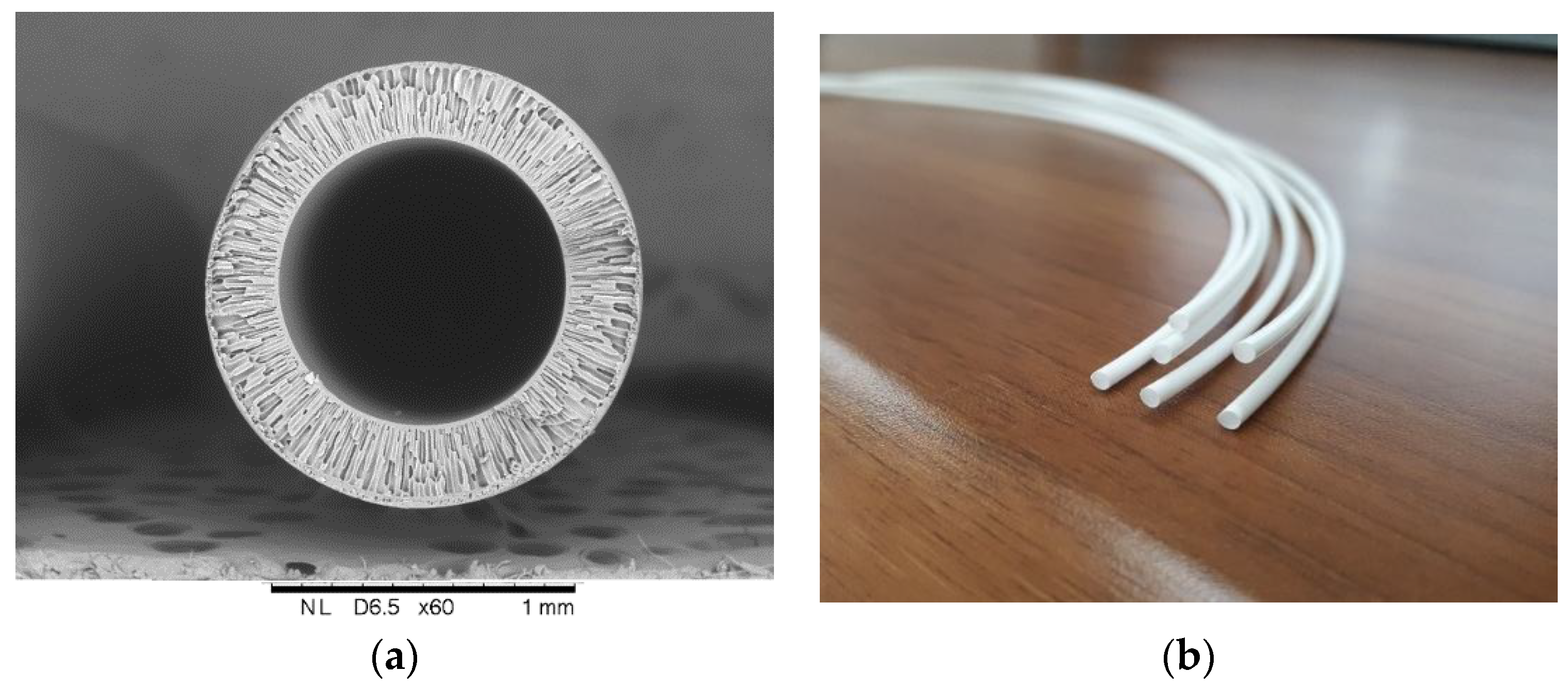
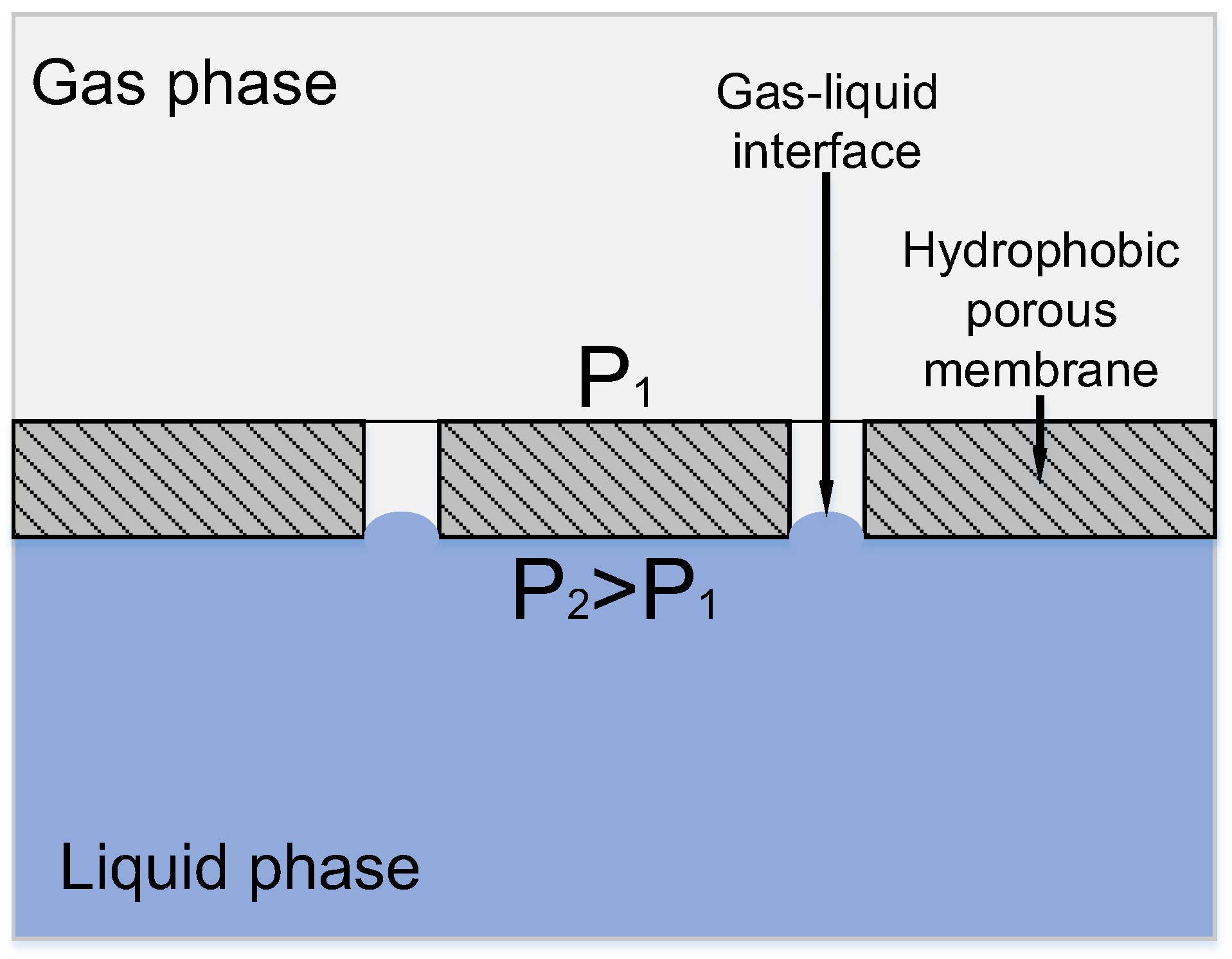
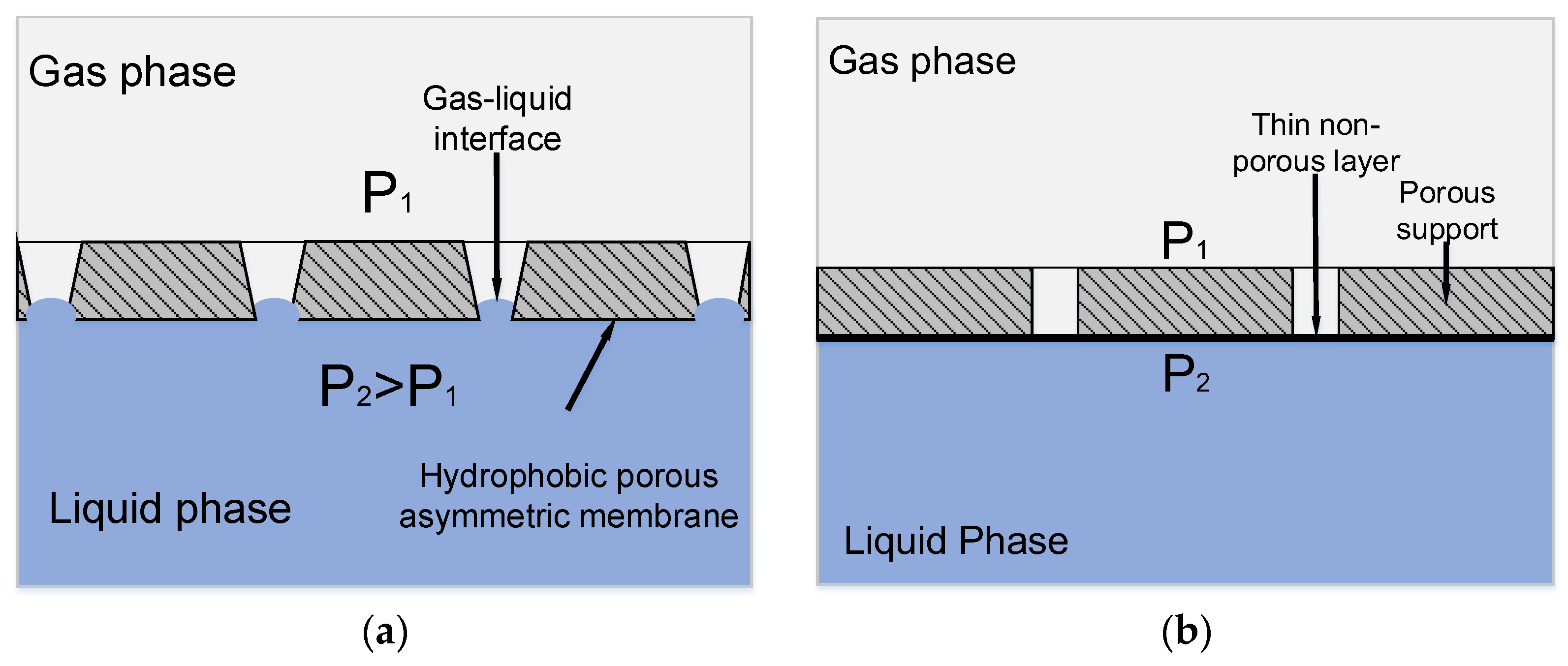
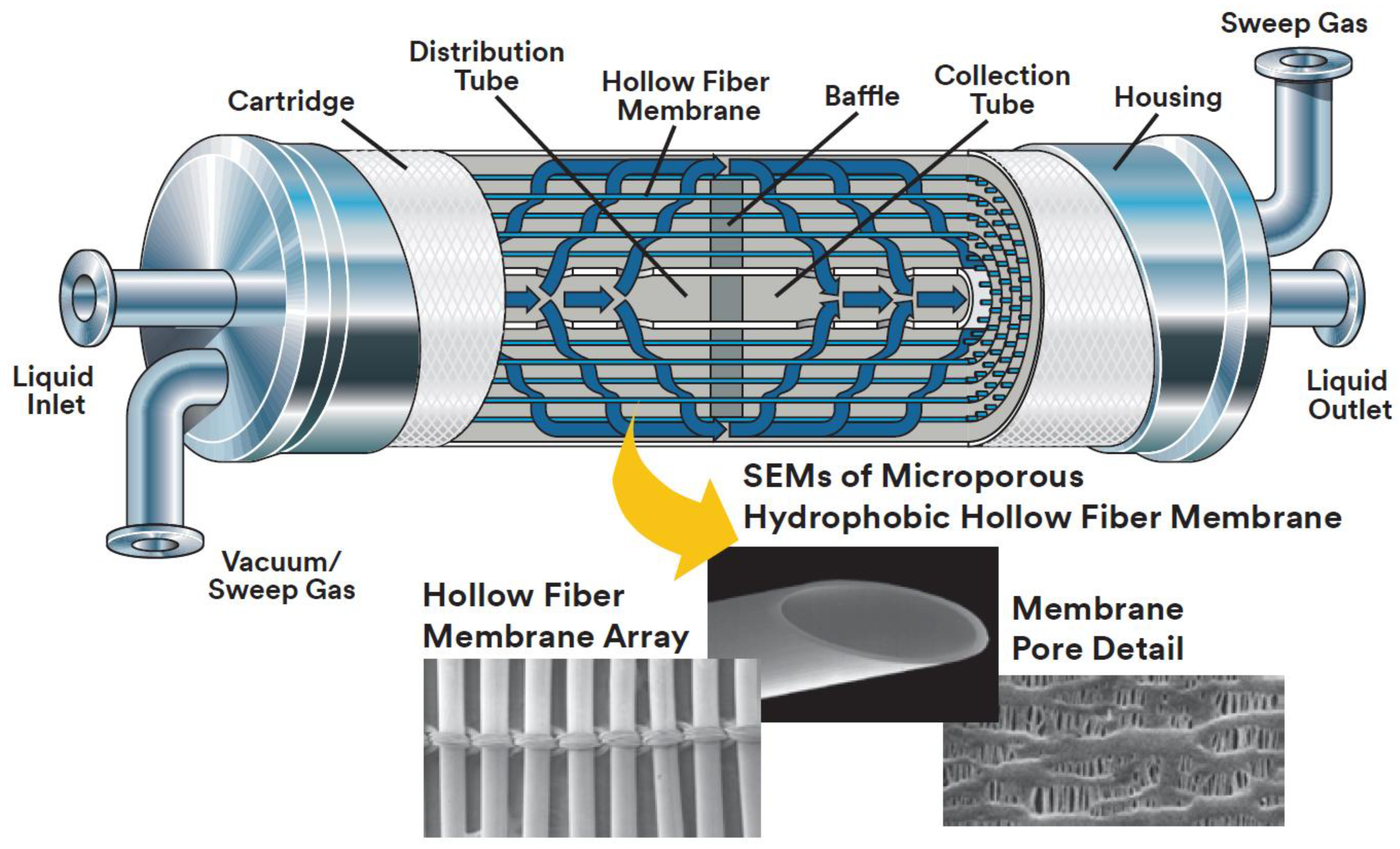
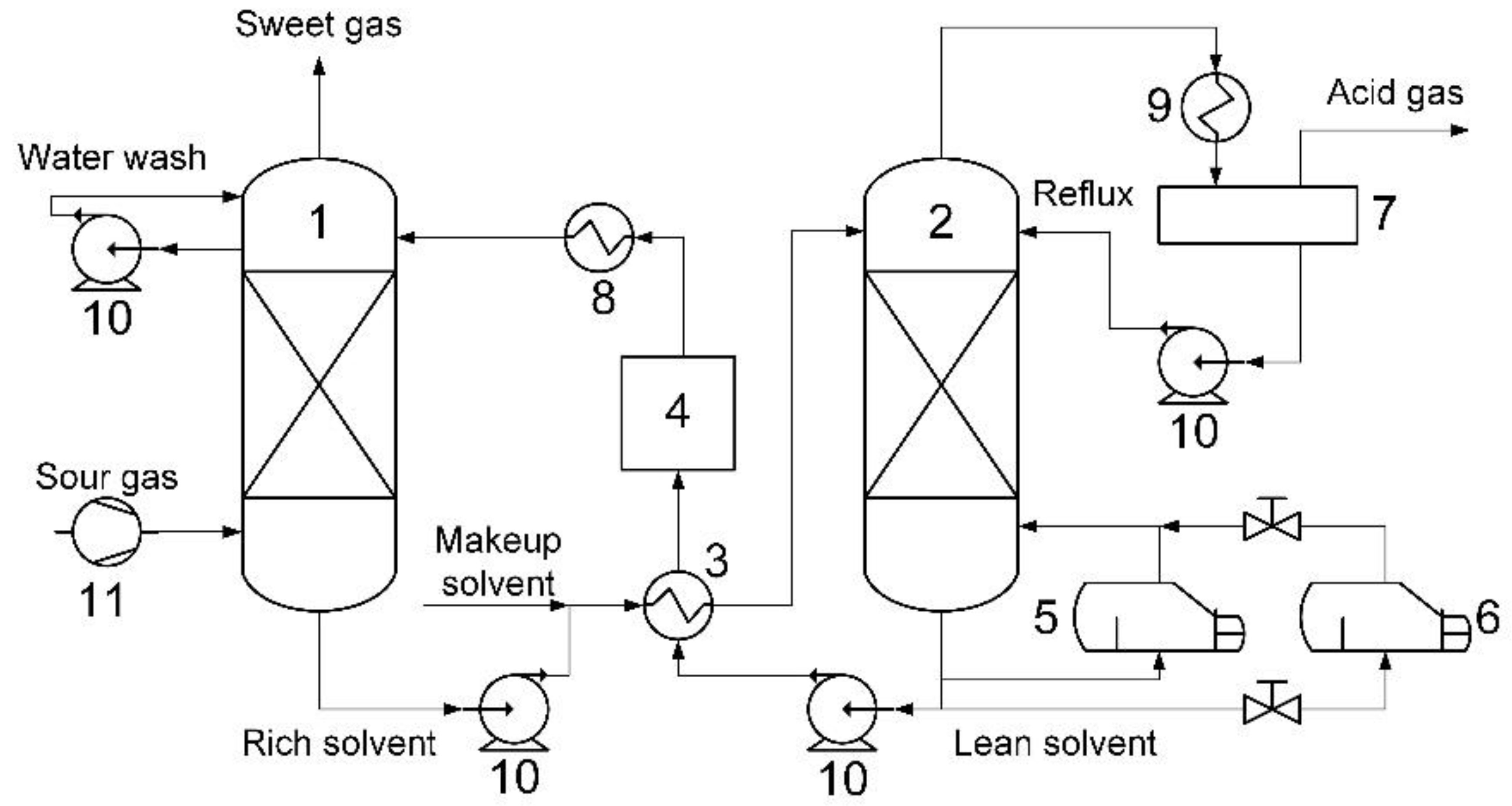
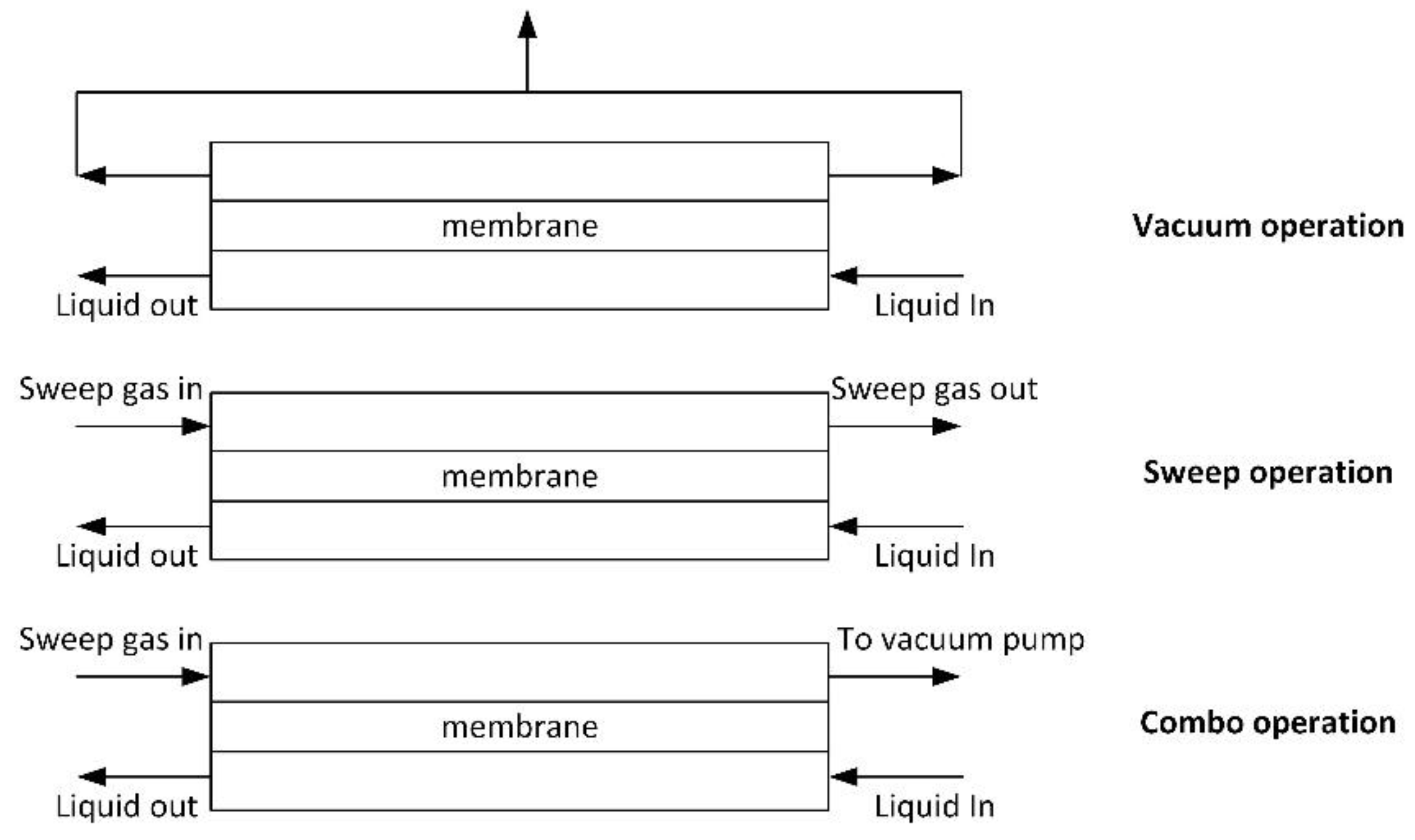
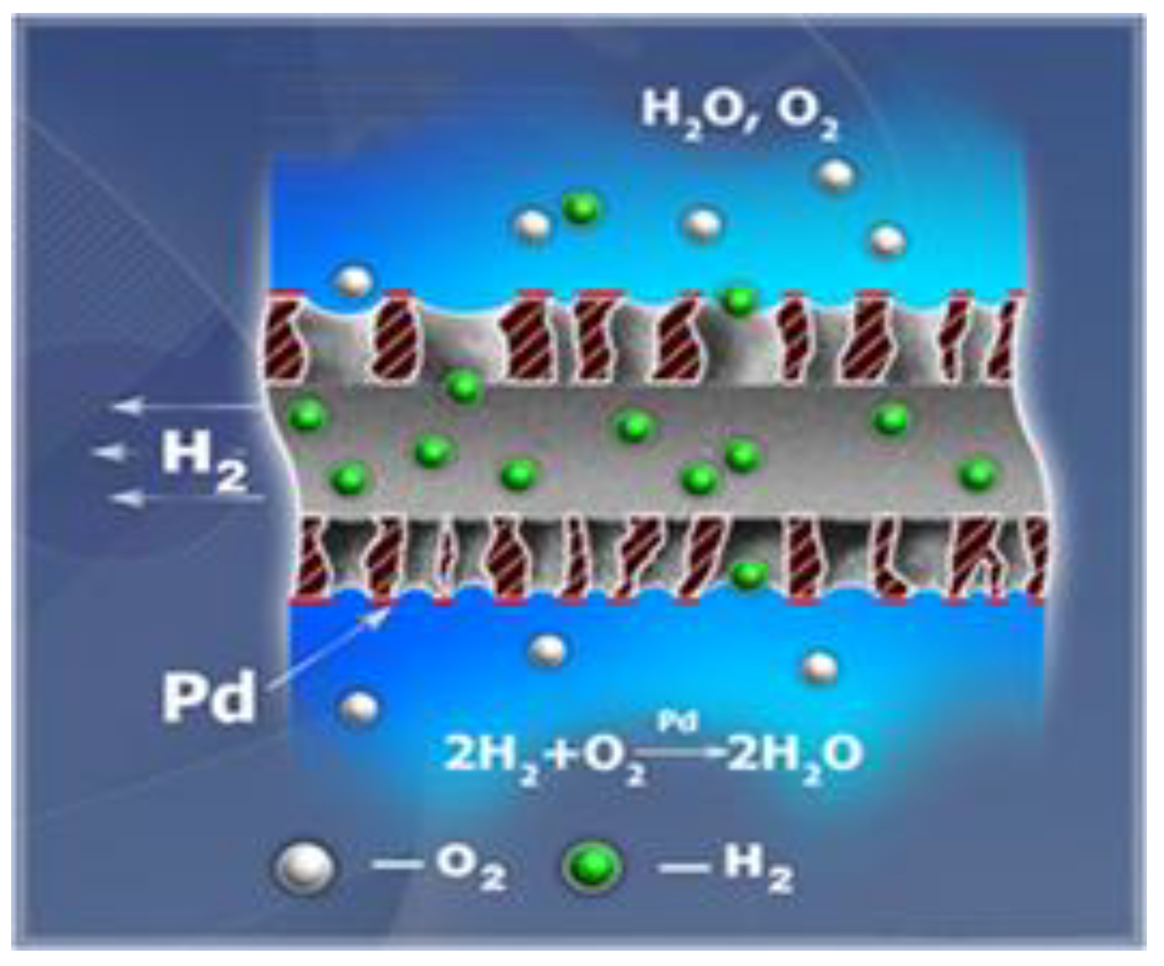
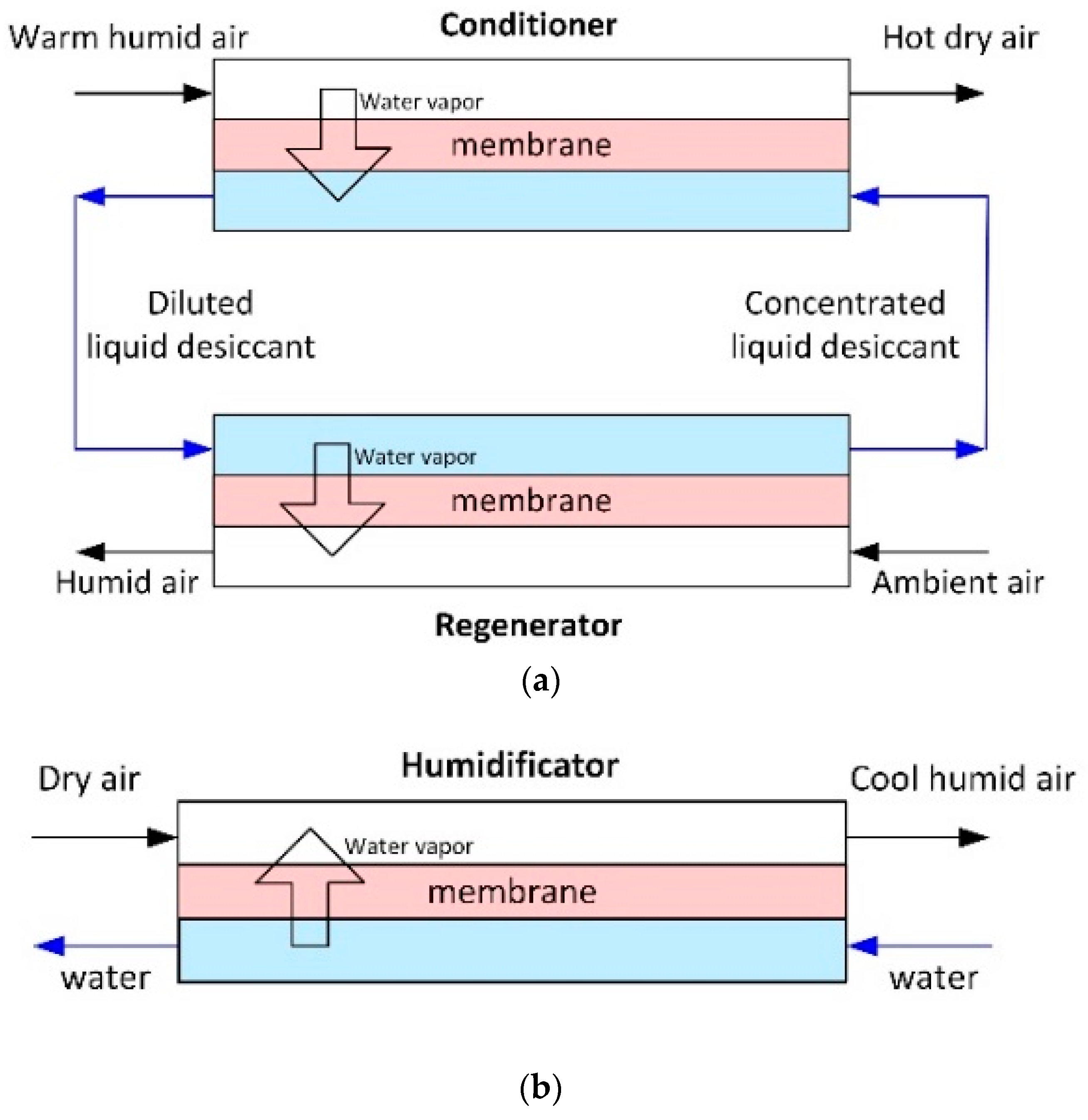
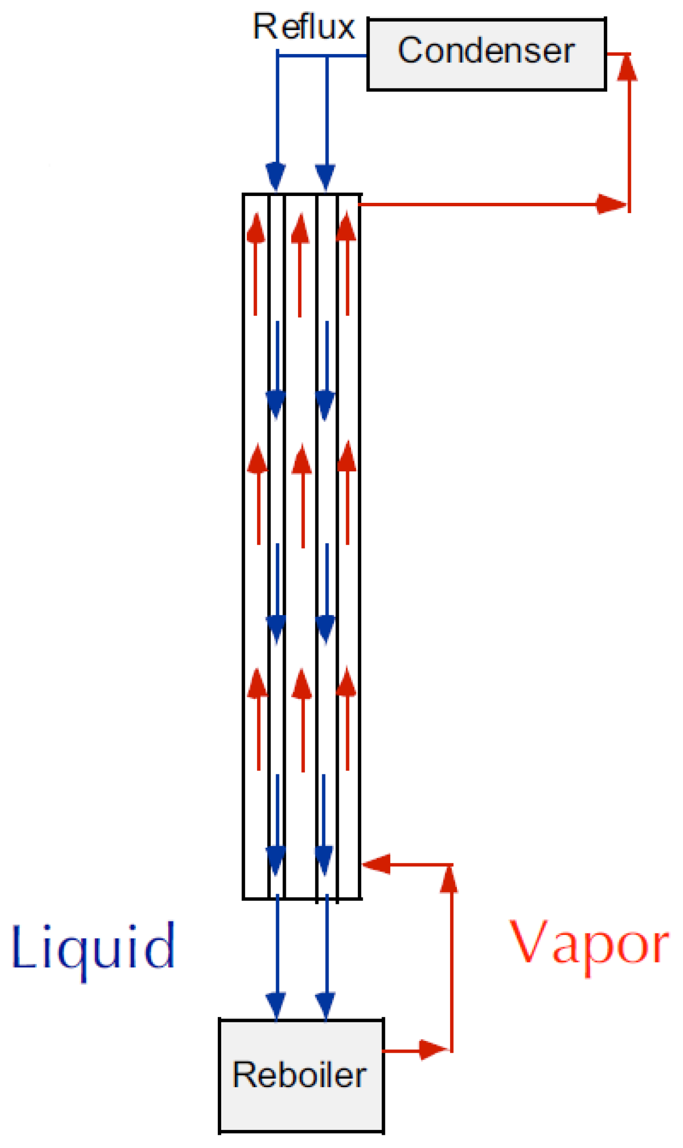
Table 1.
Chemical structures of polymer materials used for hollow fibers in membrane contactors.
| Polymer | Chemical Structure | Reference |
|---|---|---|
| Polysulfone (PSF) |  | [39] |
| Polyethersulfone (PES) |  | [40] |
| Polyether ether ketone (PEEK) |  | [41] |
| Polyetherimide (PEI) |  | [42] |
| Polyethylene (PE) |  | [43] |
| Polypropylene (PP) |  | [44] |
| Polyvinylidene fluoride (PVDF) |  | [45] |
| Polytetrafluoroethylene (PTFE) |  | [46] |
| Polymethylpentene (PMP) |  | [47] |
| Polydimethyl siloxane (PDMS) |  | [48] |
Table 2.
Studies of hydrogen sulfide removal.
| Process | Hollow Fiber Membrane Type | Contactor Design | Liquid Phase | Gas Phase | Conditions | Comments | Reference |
|---|---|---|---|---|---|---|---|
| Name of the process technology area | Name of membrane material, inner diameter/outer diameter, pore size, porosity, producer | Design of membrane contactor’s phase flow, number of membranes, active length of fibers, contact area, a—specific interfacial area (m2/m3 = m−1) | Type of liquid, content of active component, liquid flow geometry | Type of gas mixture, content of components, gas flow geometry | Gas flow rate, liquid flow rate, temperature, pressure data | Main conclusions of the work | – |
| H2S removal from natural gas | Asymmetric PVDF fiber with dense layer, 0.5/0.7 mm, Ecofine Co. (Suzhou, China); PSF, 0.25/0.55 mm, Parsian Pooya Polymer Co., (Tehran, Iran) | Parallel-flow, 91 membranes for PSF case, 56 membranes for PVDF case, length 0.2 m, contact area 0.0229 m2 for PSF case and 0.0222 m2 for PVDF case | Methyldiethanolamine (MDEA) solution in water (0.84–2.0 M), mixture of MDEA (0.84 M) and diethanolamine (1 M) in water, mixture of MDEA (0.84 M) and monoethanolamine (1 M), shell side | Gas mixtures: H2S/CO2/CH4 = (0.11–0.31)/(3–6)/(balance) vol %, lumen side | Gas flow rate 0.1–0.6 L/min, liquid flow rate 0.050–0.325 L/min, T = 298–318 K, operation pressure 0.3–0.6 bar | Both types of membranes are wetted by MDEA solution. The increasing MDEA concentration accelerates the wetting. The presence of CO2 in feed gas decreases the H2S removal. Lean MDEA solution is preferred when the goal of the system is reaching high H2S selectivity. Temperature has no significant effect on H2S removal | [52] |
| Asymmetric expanded PTFE, 1.0/2.0 mm, inner side pore size ~1–5 μm, outer side pore size ~40–80 μm, porosity 18%, Sumimoto Electric Industries (Osaka, Japan) | Counter-flow, 50 membranes, length 0.5 m, contact area 0.0785 m2 | Water, lumen side | Gas mixture: H2S/CH4 = 2/98vol %, shell side | Gas flow rate 0.4–1.0 L/min, liquid flow rate 0.025 L/min, T = 298 K, operating pressure 1–50 bar | Pseudo-wetting conditions (1–3%) of the membrane thickness show a good agreement between the H2S removal experimental data and the modelling predictions for the pressure range of 1–50 bar | [53] | |
| Poly(tetrafluoroethylene-co-perfluorinated alkyl vinyl ether) (PFA) fibers, 0.25/0.65 mm, porosity 56.8%, Entegris (Dresden, Germany) | Counter-flow, 300 or 500 membranes, length 0.14 m, contact area 0.034 or 0.055 m2 | Distilled water, NaOH solution in water (0.5 M), diethanolamine solution in water (0.5 M), K2CO3 (0.5 M), lumen side | Synthetic natural gas: H2S/CO2/CH4 = 2/5/93 vol %, shell side | Gas flow rate 1.0–4.0 L/min, liquid flow rate 0.005–0.020 L/min, T = 298–373 K, operating feed gas pressure 1–50 bar, transmembrane pressure difference 0.5 bar | The modules based on PFA hollow fibers show excellent operational stability under the conditions of high feed gas pressure and absorption liquid temperature over extended period (36 days) | [54] | |
| Asymmetric expanded PTFE, 1.0/2.0 mm, inner side pore size ~1–5 μm, outer side pore size ~40–80 μm, porosity 18%, Sumimoto Electric Industries (Japan); poly(tetrafluoroethylene-co-perfluorinated alkyl vinyl ether) (PFA) fibers, 0.25/0.65 mm, porosity 56.8%, Entegris (Germany) | Counter-flow, PTFE case: 200 membranes, length 0.5 m, contact area 0.314 m2; PFA case: 310 membranes, length 0.14 m, contact area 0.034 m2 | Distilled water, NaOH solution in water (0.1, 0.5, 1.0 M), monoethanolamine solution in water (0.5 M), diethanolamine solution in water (0.5 M), Diethylenetriamine solution in water (0.5 M), lumen side | Synthetic natural gas: H2S/CO2/CH4 = 2/5/93 vol %, shell side | Gas flow rate 0.6–1.0 L/min, liquid flow rate 0.010–0.025 L/min, T = 295 K, operating pressure 1–50 bar | PFA fibers exhibit impressive higher fluxes (9–10 times) for CO2 and H2S than those obtained with the common ePTFE fibers. Overall mass transfer coefficients are determined by the liquid phase mass transfer coefficients at low pressures, gas phase mass transfer resistance contributes considerably to the overall resistance at high pressures | [55] | |
| H2S removal from biogas | PVDF, 2.6/3.8 mm, pore size 0.2 μm, porosity 70%, Pall Corporation (New York, NY, USA) | Counter-flow, 50 membranes, length 0,2 m, contact area 0.084 m2, commercial module UMP-153 | Deionized water; monoethanolamine solution in water (0.125, 0.5, 1 M), lumen side | Gas mixture H2S/CO2/CH4 = (0–0.1)/(2–50)/(balance) vol %, shell side | Gas flow rate 0.4–0.6 L/min, liquid flow rate 0.30–1.21 L/min, T = 298 K | The use of MEA solution give much higher absorption fluxes of H2S compared to water. The absorption flux of H2S significantly increases with increasing gas flow rate and slightly increases with liquid velocity and MEA concentration. The increase in CO2 concentration decreases the H2S flux. Gas phase resistance plays the important role on the mass transfer of H2S | [56] |
| PVDF, 0.8/1.1 mm, pore size 0.2 μm, porosity 70%, Tianjin Haizhihuang Technology Co., Ltd. (Tianjin, China) | Counter-flow, 37 membranes | Water, monoethanolamine solution in water (0.05 M), K2CO3 solution in water (0.05 M), KOH solution in water (0.05 M), potassium sarcosine (PS) solution in water (0.05 M), mixed K2CO3/PS (0.025/0.025 M) solution in water, mixed K2CO3/PS (0.05/0.025 M) solution in water, mixed K2CO3/PS (0.1/0.025 M) solution in water; shell side | Gas mixtures: H2S/CO2/CH4 = (0–0.09)/(30–50)/(balance) vol %, lumen side | Gas flow rate 0.15–0.30 L/min, liquid flow rate 0.05–0.14 L/min, T = 298 K, transmembrane pressure difference 0.11 bar, operating pressure 1–4 bar | The highest H2S absorption flux is obtained when KOH and K2CO3 are used as single absorbents. H2S and CO2 absorption fluxes are higher when using promoted K2CO3 with PS than the single solvents. Increasing the concentration of CO2 and gas phase pressure increase the CO2 absorption flux and decrease the H2S absorption flux. Gas phase mass transfer resistance dominates in the mass transfer process of H2S | [57] | |
| Nonporous PDMS, 7.0/9.0 mm, EUROFLEX GmbH (Pforzheim, Germany) | Fiber immersed to absorption tank, 1 membrane, length 3.0 m, contact area 0.0659 m2 | Tap water with pH adjusted to 7, 8.5 and 10 by 1 M NaOH solution, shell side | Synthetic biogas: H2S/CO2/CH4 = 1/39/60 % vol., lumen side | Solvent stirring rate—550 rpm, gas flow rate 0.009–0.035 L/min, pH = 7–10, T = 283–318 K | Moderately high H2S fluxes (up to 3.4 g/m2⋅day) with low CH4 loss (nearly 5%) is achieved by using a robust and cost-effective tubular PDMS membrane contactor | [48] | |
| Nonporous PDMS, 7.0/9.0 mm, EUROFLEX GmbH (Germany) | Fiber immersed to absorption tank, 1 membrane, length 3.25 m, contact area 0.092 m2 | Solution of K2HPO4 (0.011 M), NH4Cl (0.0075 M), MgCl2·6H2O (0.001 M) in tap water. Solution is inoculated with two dominating sulfide oxidizing bacteria, Thiobacillus spp. and Thioalkalivibrio sulfidiphilus | Synthetic biogas: H2S/CO2/CH4 = 1/39/60 % vol., lumen side | Solvent stirring rate—550 rpm, gas flow rate 0.0056–0.0222 L/min, pH = 7–8.5, T = 303 K, operating pressure 1.01325 bar | Almost complete H2S removal (>97%) and high conversion ratio to S0 (>74%) is achieved and accordingly the calorific value of the biogas increased by about 25% | [58] | |
| H2S odor control | Asymmetric PVDF, 0.61/0.91 mm, pore size 0.0401 μm, custom-made | Counter-flow, 9 membranes, length 0.272 m, contact area 0.00699 m2, a = 1725 m−1 | 2M Na2CO3 solution in water, shell side or lumen side | Gas mixture H2S/N2 = (0.00179–0.1159)/(balance) vol %, lumen side or shell side | Gas flow rate 0.4–1.4 L/min, liquid flow rate 0.002–0.021 L/min, T = 298 K, transmembrane pressure difference 0.2 bar | When the gas mixture is fed in the shell side of contactor, the H2S removal efficiency is greatly reduced and the mass transfer coefficient is only half of that in the lumen side. The liquid velocity showed negligible influence on the outlet concentration of H2S and the mass transfer coefficient | [59] |
| PP, 0.33/0.66 mm, pore size 0.06 μm, porosity 60%, Wokingham, Berks (UK) | Counter-flow; 1st case: 1930 membranes, 0.2 m length, a = 2400 m−1; 2nd case: 120 membranes, 0.2 m length, a = 4387 m−1 | Demineralized water, pH = 7, shell side | H2S-enriched air: H2S/air = 0.01/balance vol %, lumen side | Gas flow rate 0.2–1.0 L/min, transmembrane pressure difference max. 0.345 bar gauge | Removal of H2S with substantial efficiencies of up to 89% for inlet concentrations of 100 ppm v. Gas–liquid absorption of H2S in a hollow fiber contactor is mostly membrane resistance controlled | [60] | |
| PP, 0.33/0.66 mm, pore size 0.6 μm, porosity 40% | Counter-flow, 1930 membranes, length 0.2 m, contact area 0.4 m2, a = 2400 m−1 | NaOH solutions in water, pH = 7–13, lumen side | Synthetic odorous air: H2S/N2 = (0.0003–0.01)/(balance) vol %, shell side | Gas flow rate 0.25–25.00 L/min, liquid flow rate 0.059–0.703 L/min, T = 298 K, transmembrane pressure difference 0.5 bar | A solvent concentration of pH = 11 is found to be most economically attractive. This NaOH concentration facilitates efficient H2S removal at concentrations several orders of magnitude below those proposed in previous contactor studies | [61] |
Table 3.
Studies on sulfur dioxide removal.
| Process | Hollow Fiber Membrane Type | Contactor Design | Liquid Phase | Gas Phase | Conditions | Comments | Reference |
|---|---|---|---|---|---|---|---|
| Flue gas desulfu-rization | PSF, 0.2/0.4 mm, pore size 0.05, 0.1 μm, PHILOS Co. (Pohang, Korea); PP, pore size 0.03 μm, Celgard®, Polypore International, Inc. (Charlotte, NC, USA) | PHILOS module: 0.15–0.294 m length, Liqui-Cel® membrane modules | Water, NaOH (0.02–2.0 M) solution in water, Na2CO3 (0.02 M) solution in water, Na2SO3 solution in water (0.02 M), NaHCO3 solution in water (0.02 M), lumen side | SO2–enriched air: SO2/air = (0.04–0.02)/(balance) vol %, shell side | Gas flow rate 2–16 L/min, liquid flow rate 0.001–0.060 L/min | SO2 removal efficiency decreases with increasing the gas flow rate but increases with the pore size. The performance of Na2CO3 is shown to have the highest SO2 removal efficiency among the solvents studied. | [62] |
| PP, 0.38/0.5 mm, pore size 0.16 μm, porosity 65%, Tianjin Blue Cross Membrane Technology Co., Ltd. (Tianjin, China) | Counter-flow, 600 membranes, 0.3 m length, HDMF-100–1 module type | Monoethanolamine solution (0.5 M) in deionized water, lumen side | Gas mixture: SO2/CO2/N2 = 1.6/20/78.4 vol %, shell side | Gas flow rate 0.05–0.25 L/min, liquid flow rate 0.009–0.045 L/min, T = 293 K, operating pressure 1 bar | The removal efficiencies and mass transfer rates of CO2 and SO2 are improved by increasing the liquid and gas flow rates. The existence of SO2 had a slight influence on the CO2 absorption due to the reaction competition with CO2. Membrane wetting occurred over prolonged operation. | [44] | |
| PP, 0.2/0.3 mm, pore size 0.03 μm, porosity 25%, Celgard® X-40, Polypore International, Inc. (USA) | Transverse-flow, 11100 membranes, 0.16 m length, Liqui-Cel® 2.5 × 8 Extra-Flow Module | Deionized water, shell side | Gas mixture: SO2/N2 = (0.1–0.3)/(balance) vol %, lumen side | Gas flow rate 8.3–18.1 L/min, liquid flow rate 0.194–0.463 L/min, T = 300 K, transmembrane pressure difference 0.07–0.21 bar | Experimental and modelling results show that the mass transfer resistances of membrane, shell side and lumen side are all significant along the axial position due to high gas solubility and partial wetting of fiber pores. A 9% of wetting ratio of pore length increases the membrane resistance by 5 times in comparison with that at non-wetted condition. | [63] | |
| Asymmetric PVDF, 0.765/0.986 mm, pore size 0.772 μm, custom-made | Counter-flow, 20 membranes, 0.125 m length, contact area 0.00602 m2, a = 630 m−1, 3 modules connected in series | Water, NaOH (0.01–2.0 M) solution in water, Na2CO3 (0.02 M) solution in water, Na2SO3 solution in water (0.02 M), NaHCO3 solution in water (0.02 M), shell side | Gas mixture: SO2/N2 = (0.02–0.20)/(balance) vol %, lumen side | Gas flow rate 2–15 L/min, liquid flow rate 0.0011–0.0143 L/min, gas phase pressure 0.46 bar | The SO2 removal efficiency of ~85% is achieved with 2 M NaOH solution. The absorption efficiency of aqueous solutions of various chemicals is compared and Na2CO3 is found to be the most promising absorbent among them. | [64] | |
| Ceramic fiber: α-Al2O3, 3.0/4.0 mm, pore size 0.1 μm, HyfluxTM Ceparation BV (Helmond, The Netherlands) | Counter-flow, 280 membranes, 0.44 m length, contact area 0.8 m2 | N,N-dimethylaniline, lumen side | SO2-enriched air: SO2/air = (0.15–4.8)/(balance) vol %, shell side | Gas flow rate 1 L/min, liquid flow rate 0.1–1 L/min, T = 289 K, transmembrane pressure difference 0.02 bar | 40–50% of sulfur dioxide can be recovered using a ceramic hollow fibre contactor and N,N-dimethylaniline. The main resistance is found to be the ceramic membrane. | [65,66] | |
| Ceramic fiber: α-Al2O3, 3.0/4.0 mm, pore size 0.1 μm, HyfluxTM Ceparation BV (The Netherlands) | Counter-flow, 280 membranes, 0.44 m length, contact area 0.8 m2 | Ionic liquid 1-ethyl-3-methylimidazolium ethylsulfate, lumen side | Gas mixture: SO2/CO2/air = 3.3/(0–10)/(balance) vol %, shell side | Gas flow rate 1 L/min, liquid flow rate 0.1–1 L/min, T = 289 K, liquid phase pressure 1.125 bar, gas phase pressure 1.1 bar | Higher resistance to mass transfer when the ionic liquid applied compared to N,N-dimethylaniline. Membrane resistance is the main contribution to be taken into account. Wetting fraction (ratio of the pore length wetted by liquid to the total length) is approx. 4%, compared to 74% for N,N-dimethylaniline. | [67,68] | |
| PP, 0.5/0.6 mm, pore size 0.07–0.1 μm | Counter-flow or parallel-flow, 64 membranes, 0.22 m length, contact area 0.0265 m2 | Seawater (pH = 8.2–8.35, alkalinity (1.94–2.22) × 10−3 M, tap water, NaOH solution in water (pH = 8.35), shell side | SO2-enriched air: SO2/air = (0.15–0.21)/(balance) vol %, lumen side | Gas flow rate 1.67–8.33 L/min, liquid flow rate 0.17–1.5 L/min, T = 295 K, gas phase pressure 0.1–0.2 bar, liquid phase pressure 0.09–0.21 bar | Under the same operating conditions, seawater keeps a high SO2 overall mass transfer coefficient which is about twice as large as that of the aqueous NaOH solution. The seawater absorption coupled with membrane contactor has a very low height of transfer unit value compared with conventional packed tower. | [80] | |
| Pilot studies of flue gas desulfuri-zation | PP, n.a./0.6 mm | Transverse-flow | Na2SO3 solution in water, lumen side | SO2-containing flue gas from steam boiler with combustion of H2S containing biogas of potato starch production plant of AVEBE (Veendam, The Netherlands), shell side | Gas flow rate up to 1666.67 L/min | A SO2 recovery of over 95% is obtained at a capacity of 120 m3/h. During the experiments (2 production seasons, each 6 months long) no fouling of the membranes or decline in mass transfer are observed. | [78,79] |
Table 4.
Studies on membrane oxygenation/deoxygenation.
| Process | Hollow Fiber Membrane Type | Contactor Design | Liquid Phase | Gas Phase | Conditions | Comments | Reference |
|---|---|---|---|---|---|---|---|
| Dissolved oxygen removal from water | PP, 0.24/0.3 mm, or 0.40/0.46 mm, porosity 20%, Celgard® X10 fiber mat, Hoechst Celanese Corporation, (Charlotte, NC, USA) | Parallel-flow, counter-flow, transverse flow, 0.007–0.168 m length, contact area 0.0622–0.34 m2, 29–50 fibers per inch of fabric, one-, two-, four-, five-baffle designs | Water saturated with O2 from air, shell side | Nitrogen as sweeping gas with transferred O2 and water vapors, lumen side | Liquid Re = 0.2–40 | The best performance is achieved by the module with five baffles operating in countercurrent flow. The module with two baffles operated in countercurrent flow is almost as good. | [30,104] |
| PP, 0.34/0.40 mm, pore size 0.03 μm, porosity 33%, Hoechst Celanese Corporation, Charlotte (USA) | Parallel-flow, counter-flow, 100–500 membranes, 0.06–0.71 m length, contact area 0.0081–0.409 m2 | Deionized water saturated with O2 (8 ppmw), lumen side | Nitrogen as sweeping gas with transferred O2 and water vapors, shell side | Gas flow rate 0–16.8 L/min, liquid flow rate 0.03–0.102 L/min, T = 295 K | Hollow fiber modules containing hydrophobic membranes are capable to reduce dissolved oxygen to 3 orders of magnitude to the 8 ppb (parts per billion) concentration range in ultrapure water production. The overall mass transfer coefficients of oxygen are observed to be dominated by the individual mass transfer coefficient in the liquid film. | [31] | |
| Nonporous silicone rubber, 0.2/0.32 mm, Nagayanagi Kougyou (Nagoya, Japan) | Counter-flow, 6000 membranes, length 0.14 m, contact area 0.495 m2 | Ultra pure water with adjusted O2 level (0.5–6.4 ppmw), lumen side | Vacuum with transferred O2 and water vapors; N2 as sweeping gas; shell side | Liquid flow rate 0.4–1.4 L/min, T = 293–295 K, vacuum pressure 0.05–0.60 bar absolute | Although the liquid-phase mass transfer resistance is shown to have a large effect on the removal performance of the membrane module, the non-porous membrane permeation step controls the mass transfer during vacuum oxygen removal. A gas-phase driving force model is presented based on the permeabilities of the permeates through the hollow-fibers. | [85] | |
| Hydrophilic PSF, 0.6/0.7 mm, pore size 0.2 μm, X-Flow (Almelo, The Netherlands) | Transverse-flow, 1058 membranes, length 0.14 m, contact area 0.326 m2 or 0.279 m2 | Water with adjusted O2 level (8–9 ppmw), shell or lumen side | O2 in case of oxygenation or N2 as sweeping gas in case of deoxygenation, shell or lumen side | Liquid flow rate 0.005–0.05 L/min, gas flow rate 0.33–1.0 L/min, T = 291 K, transmembrane pressure difference 0.02–0.04 bar | An increase of water flow increases the liquid mass-transfer coefficient (decreases the overall resistance) to a limiting value corresponding to the membrane resistance. For water flow inside the fibers, oxygen removals as high as 99.6% is achieved. | [39] | |
| PE, n.a./0.4115 mm, pore size ~0.1 μm, porosity ~60%, Mitsubishi Rayon Co. Ltd. (Tokyo, Japan) | Counter-flow, 1500 membranes, length 1.55 m, contact area 3.0 m2, Membran Corporation (Minneapolis, MN, USA) | Air-saturated tap water, shell side | Vacuum with transferred O2 and water vapors, lumen side | Liquid Re = 500–8000, T = 283–298 K, vacuum pressure (6–10) × 10−5 bar | The mass transfer coefficient is controlled by the resistance in the liquid phase. At Reynolds numbers below 2500–3000 the performance of the degassing system is controlled by the mass transfer across the membrane. A large component of the total gas pressure within the fiber lumen is due to the water vapor flux. | [43] | |
| 1st case: PP, 0.21/0.26 mm, Celgard X30, Membrana GmbH (Wuppertal, Germany); 2nd case: composite membrane with thin nonporous layer of perfluorodimethyldioxole-tetrafluoroethylene (PDD-TFE) on PP support (Celgard X30); 3rd case: PP, 0.24/0.30 mm, Celgard X10, Membrana GmbH (Germany) | 1st and 2nd case: cross-flow, 3300 membranes, contact area 0.8 m2, Minimax PlusTM blood oxygenator modules, Medtronic Inc., (Minneapolis, MN, USA); 3rd case: parallel-flow, 7500 membranes, contact area 1.7 m2, Liqui-Cel® module, Hoechst-Celanese | Degasification mode: water saturated with O2 (8 ppmw) or CO2. (4.4–440 ppmw). Absorption mode: deionized water. Shell side | Degasification mode: vacuum with transferred O2, CO2 and water vapors. Absorption mode: pure O2 or CO2. Lumen side | Liquid flow rate 0.03–0.85 L/min, T = 292–294 K, vacuum pressure 0.0013–0.0067 bar | Crossflow blood oxygenators are highly efficient for high vacuum-driven individual removal of O2 and CO2 as well as the simultaneous removal of O2 and CO2 from water. Fibers with PDD-TFE thin layer provide reduced degasification performance but good stability to microbiocontamination. | [91] | |
| PP, 0.39/0.65 mm, pore size 0.2 μm, MEMCOR CMF-S S10T, MEMCOR (South Windsor, Australia) | Fiber sealed-end design, counter-flow, 0.4–0.8 m length, 18 sealed-end modules, packing density 2.93–52.8% | Air-saturated water, shell side | Vacuum with transferred O2 and water vapors, lumen side | Liquid velocity 0.25–2.25 m/s, T = 293 K | The oxygen flux and mass transfer coefficient decrease with increasing module-packing density for the same water velocity. The mass transfer coefficients are independent of fiber length within study. At the same Reynolds number, pressure drops increase with increasing packing density due to an increase in friction between fibers and water. | [83] | |
| Silicon rubber fibers, 0.3/0.64 mm, SILASTIC®, DowCorning (Midland, MI, USA) | Counter-flow, 100 membranes, length 0.71 mm | Deionized water saturated with air (O2 level 7.1–8.2 ppmw), lumen side | Vacuum with transferred O2 and water vapors or N2 as sweeping gas with transferred O2 and water vapors, shell side | Liquid flow rate 0.08–0.30 L/min, sweeping gas flow rate 0.2–1.2 L/min, T = 295 K, vacuum pressure 0.04–0.75 bar | The water vapour permeation enhances the mass transfer of oxygen across the membrane, and hence favors the dissolved oxygen removal. As the module length increases, the improvement on the O2 removal due to water vapour permeation would diminish. Using the vacuum degassing, length of the hollow fibre modules has to be restricted in order to maintain the efficiency of dissolved oxygen removal. | [81] | |
| Helical fibers coiled around a core (a stainless tube), 0.5–0.7 mm or 0.8–1.1 mm, | Counter-flow, 15–82 membranes, length 0.14–0.28 m, contact area 0.0145–0.036 m2, coiled and straight modules | Air-saturated water, lumen or shell side | Pure N2 as sweeping gas, lumen or shell side | Liquid velocity 0.06–0.9 m/s | Mass transfer can be remarkably enhanced in both lumen side and shell side in coiled modules with helical hollow fibers. The maximum improvement factor obtained is 3.5 for mass-transfer coefficient. | [105] | |
| PP, 0.3/0.7 mm, pore size 0.32 μm, Shandong Zhaojin Motian Company (Zhaoyuan, China); PVDF, 0.8/1.1 mm, pore size 0.26 μm, Tianjin Motian Membrane Eng. &Tech. Company (Tianjin, China) | Parallel-flow, PP case—120 membranes, PVDF case—60 membranes; length 0.12 m, contact area 0.02125 m2, batch operation | O2-saturated water, shell side | Vacuum with transferred O2 and water vapors, lumen side | T = 298 K, vacuum pressure 0.3–0.9 bar, ultrasonic power 40–100 W, distance from the bottom of the reservoir 0.5–9.5 cm, ultrasonic frequency 40 kHz | Mass transfer is greatly improved by ultrasound stimulation for PP and PVDF membranes with enhancement factor up to 2.0. The degradation of PP and PVDF under ultrasonic influence enlarges the membrane pore, leads to the overall increase in pore density and porosity, the formation of holes and cracks. | [90] | |
| PP, 0.2/0.3 mm, Celgard X40 | Transverse-flow, 10,200 membranes, length 0.16 m, contact area 1.4 m2, Liqui-Cel® 2.5 × 8 Extra-flow module | NaCl solution in water (0.02 M, 0.82 M, 2.65 M, 4.33 M), shell side | Vacuum with transferred O2 and water vapors, lumen side | Liquid flow rate 1.67–11.67 L/min, T = 293–313 K, vacuum pressure 0.05–0.08 bar | The performance of the Liqui-Cel® 2.5 × 8 module membrane contactor shows high oxygen removal (between 60% and 98%) from NaCl solutions, leading to oxygen concentrations in salt solutions as low as 70 ppb. | [87] | |
| Asymmetric PVDF triple-bore hollow fibers, i.d. of each lumen tube 0.67 mm/1.6 mm o.d. of membrane, pore size 0.0126 μm, porosity 75%, custom-made | Counter-flow, 200 membranes, contact area 0.3 m2, 2 modules in series or in parallel | Deionized water, fish ponded water (pH = 6.4, total suspended solids 3245 mg/L, chemical oxygen demand 43 mg/L), lumen side | Vacuum with transferred O2 and water vapors, shell side | Liquid flow rate 0–0.5 L/min | High oxygen removal rate for deionized water (97.5%). Lower oxygen removal rate for aquaculture water (87.3%). Membrane fouling is observed whether the aquaculture water is pre-treated or not. Membranes could be cleaned with NaOH. | [45] | |
| Counter-flow, 200 membranes, length 0.24 m, contact area 0.3 m2, 2 modules in series | Tap water, lumen side | Vacuum with transferred O2 and water vapors, shell side | Liquid flow rate 0.02–0.90 L/min, T = 298 K, vacuum pressure 0.3725–0.982 bar | Water evaporation and water vapor condensation affect the deoxygenation performance but both are not avoidable for vacuum degassing systems. The highest oxygen removal efficiency is 82% and can be achieved with medium water flow rates and highest vacuum level. | [95,96] | ||
| Catalytic dissolved oxygen removal from water | Catalytic PP fibers with adlayered palladium nanoparticles, 0.22/0.30 mm, pore size—less than 0.03 μm, surface porosity 12–17%, initial PP membranes—Celgard X50 fabric, provided by Celgard, (USA) | Transverse flow, membrane fabric winded around polymer axial tube with large pores, contact area 0.05–0.07 m2 | Air-saturated water, shell side | Pure H2, lumen side | Liquid flow rate 0.083–0.417 L/min, T = 298 K, transmembrane pressure difference 0.1 bar | Catalytic nanoparticles are successfully deposited onto the surface of hydrophobic porous PP hollow fiber membranes by the chemical reduction of palladium acetate. The performance of catalytic membrane is controlled by the amount of the deposited catalyst. The kinetics of dissolved oxygen removal is limited by oxygen delivery to the surface of catalytic particles. | [92] |
| Catalytic PP fibers with adlayered palladium nanoparticles, 0.6/1.0 or 1.8/2.7 mm, pore size—less than 0.2 μm, initial PP membranes—Accurel Q3/2 or Accurel S6/2 provided by MEMBRANA GmbH (Germany) | Fibers immersed to water tank, length 0.22 m | Air-saturated water, shell side | Pure H2, lumen side | Constant stirring of liquid, gas flow rate 0.006 L/min, T = 293 K | Palladium is deposited on a hydrophobic porous PP fibre, while maintaining its hydrophobic nature. The hydraulics in the membrane module are rate limiting. The possibility of efficient water deoxygenation at room temperature is demonstrated. | [93,94] | |
| Pilot studies of dissolved oxygen removal from water | PP, 0.24/0.3 mm | Transverse flow, 10,200–224,640 membranes, length 0.16–0.62 m, contact area 1.2–129.7 m2, 4 different individual modules of Liqui-Cel®, Celgard LLC | Air-saturated water (O2 level—9 ppmw), shell side | N2 as sweeping gas from the inlet of fiber, vacuum from the outlet of the fiber, lumen side | Liquid flow rate 1.92–796.74 L/min or 226.7–795 L/min for 4-module system, T = 293 K, vacuum pressure 0.0667 bar | 4-module system is capable to remove O2 from water up to 5.6 ppbw at pilot water flow rate 47.7 m3/h. A simple model of mass transfer was developed for the transverse-flow design predicted the separation performance quite well. | [82] |
| PP, 0.3/0.4 mm, pore size 0.08 μm, porosity 40%, PP fibers as fabric | Transverse-flow, length 0.22–0.8 m, contact area 3.7–81 m2, Hyflux proprietary membrane contactor with woven fabric | Reverse osmosis-treated water, shell side | Vacuum with transferred O2 and water vapors, lumen side | Liquid flow rate 0–66.67 L/min, T = 298 K vacuum pressure 0.06 bar | The first pilot membrane degassing system integrated with a reverse osmosis water production line for the removal of dissolved oxygen by membrane contactors packed with woven fabric. | [84] | |
| PP, 0.1/0.3 mm, Shanghai Shenyu Scientific Corporation (Shanghai, China) | Transverse-flow, contact area 42 m2 | O2-saturated water (O2 level—8.5–11.5 ppmw), shell side | Vacuum with transferred O2 and water vapors, lumen side | Liquid flow rate 0–83.33 L/min, liquid temperature T = 283–298 K vacuum pressure 0.01–0.1 bar | Membrane module used is a highly efficient mass transfer device. The oxygen removal efficiency and mass transport coefficient decrease dramatically after long time ran using surface water as source boiler feed water due to membrane fouling by organic matter and aluminum silicate. | [86] | |
| PP, 0.2/0.3 mm, X-IN type | Transverse flow, 3 modules in series, Liqui-Cel® modules Company | Tap water (O2 level—10.98 ppmw), shell side | N2 as sweeping gas from the inlet of fiber, vacuum from the outlet of the fiber, lumen side | Liquid flow rate 333.33 L/min, gas flow rate 100 L/min per each module. T = 285 K, vacuum pressure 0.2 bar | With lower nitrogen purity, O2 concentrations in outlet water are increased, and O2 removal efficiency is decreased. With membrane process, price of treated water is 1.58 EUR/m3, while for thermal process—2.99 EUR/m3. | [89] | |
| Bubble-less membrane aeration | Untreated or alcohol-treated PP, 0.35/0.44 mm, pore size 0.15 μm, porosity 44.7%, Join Future Membrane Technology Co. (Zhejiang, China) | Cross-flow or parallel-flow, 3950 membranes, length 0.2 m | Tap water, shell side | The air, lumen side | Liquid flow rate 0.83–6.67 L/min, gas pressure 0.2–1.0 bar | The operating pressure in both cross flow and parallel flow modules are shown to be elevated up to 100 kPa without bubble formation. The oxygen transfer performance is improved significantly by designing module configurations, enhancing the operating pressure and increasing the water flow rate. | [106] |
| Membrane contactor as “artificial gill” | Ethylene-vinyl alcohol copolymer (EVAL), 0.2/0.214 mm, KF-101-1200, Kawasumi Laboratories (Tokyo, Japan) | Counter-flow, 8000 membranes, contact area 1.5 m2 | Perfluorooctylbromide (PFOB), shell side | Air, lumen side | Gas flow rate 0.6 L/min, liquid flow rate 0.3 or 0.5 L/min, T = 298 K | O2 transfer through the membrane from PFOB to air is found to be the rate determining step. Use of PFOB gives a stable supply of oxygen from water to deoxygenated air over long periods. | [107] |
| PP, 0.2/0.3 mm | Transverse-flow, length 0.889 m, contact area 20 m2, Liqui-Cel® modules | Water, shell side | Vacuum with transferred O2 and water vapors, lumen side | Separated gas flow rate 0.2–1.0 L/min, liquid flow rate 40–80 L/min, vacuum level 0.267–0.933 bar | Until 26.7 kPa, there is no permeation of water, through hollow fiber membrane module. O2 concentration in separated dissolved gases is increased in comparison with one in the air. | [108] | |
| PP, 0.2/0.3 mm | Transverse-flow, length 0.512 m, contact area 8.1 m2, two Liqui-Cel® modules in portable system | Water, shell side | Vacuum with transferred O2 and water vapors, lumen side | Separated gas flow rate 32 L/min, liquid flow rate 1.94 L/min | A portable low-weight separation system of dissolved O2 is proposed. Composition of dissolved O2 contained in gases separated from water is shown to be 29.071%. | [109] | |
| Oxygen absorption, particularly from air | PP, 0.6/1.0 mm | Counter-flow, 85 membranes, length 0.24 m, contact area 0.04 m2, LM2P-06 module, Enka-Labor (Obernburg, Germany) | Pure water, pseudo-plastic non-Newtonian sodium carboxymethylcellulose (CMC) solutions in water (5, 10, 20 kg/m3) | Pure O2, shell or lumen side | Gas flow rate 1.67 L/min, T = 295 K, operation pressure 1 bar | For both flow configurations, an increase of CMC concentration of CMC solutions leads to an increase in mass transfer resistance in the liquid phase. The liquid mass-transfer reduction is attributed to higher density and apparent viscosity of the pseudo-plastic solution. | [97] |
| PP, 0.22/0.45 mm, pore size 0.1–0.2 μm, porosity 50%, Parsian Pishro Sanat Polymer Co. (Karaj, Iran) | Counter-flow, length 0.35 m, contact area 1 m2 | Slaughterhouse wastewater including about 90% (v/v) blood, sodium citrate 4% (w/w) as anticoagulant, shell or lumen side | Humidified ambient air, shell or lumen side | Gas flow rate 0.004–0.100 L/min, liquid flow rate 0.15–1.00 L/min, T = 298 K, liquid operating pressure 1.1 bar | For mode of wastewater flowing through the lumen side, higher removal efficiencies are attributed to less dead zones, but membrane fouling is a problem. | [99] | |
| PP fibers, Celgard X50 | Transverse-flow, contact area 0.2 m2, commercial module number G543, 3M (USA) | Polyethyleneimine (PEI) cobalt complex (PEI-Co) solution in water, PEI/Co ratio—10, shell side | Air, lumen side | Liquid flow rate 0.005–0.05 L/min, gas flow rate 0.005–0.015 L/min, T = 298 K, operation pressure 1 bar | Novel hollow fiber membrane contactor with novel oxygen carrier solution produces O2 with 99.6% purity. The carrier solution has extremely high oxygen absorption capacity (up to 1.5 L per litre solution). | [98] | |
| Membrane blood oxygen-nation | 0.2/0.3 mm, fibers as fabric | Transverse-flow, 14,500 membranes, 2 modules, commercial blood oxygenators with fabric wound around a central tube in order to form a fibre bundle, Cobe Optima XP, Cobe Cardoivascular Inc., (Arvada, CO, USA) | Deionized water, water/glycerol mixtures: 95:5, 90:10, 80:20, 70:30, 60:40, 50:50 (w:w), shell side | 1st module: liquid-saturated O2, lumen side; 2nd module: liquid-saturated N2 as sweeping gas, lumen side | Gas flow rate 0.81 or 2.11 L/min, liquid flow rate 0.5–11 L/min, operation pressure 1 bar | Blood oxygenation modelling. By varying the kinematic viscosity of the liquid stream and the O2 diffusion coefficient in the liquid stream, the dependence of the Sherwood number on the Schmidt number is determined. The Sherwood number does depend on the Schmidt number raised to the one-third power. | [103] |
| Plasma-activated PMP fibers modified by grafting of 2-methacryloyloxyethyl phosphorylcholine, 0.2/0.35 mm, initial PMP membranes—QUADROXTM, provided by MAQUET Getinge Group (Rastatt, Germany) | Parallel-flow | Porcine venous blood contacted with CO2 and N2, shell side | Pure O2, lumen side | Gas flow rate 0.3 L/min, liquid flow rate 0.06 L/min | The modified PMP surface exhibited improved hemocompatibility compared with pristine surfaces. O2-CO2 gas exchange rates slightly decreases because of surface hydrophilic wetting. | [47] | |
| Asymmetric PMP, n.a./0.38 mm, PMP fibers as fabric, OXYPLUS PMP, Membrana GmbH (Germany) | Transverse-flow, 44 fibers per inch of fabric | Pure glycerol solution (average nominal kinematic viscosity-400 cSt) | n.a. | n.a. | Blood oxygenation modelling. The Darcy permeability of hollow fiber bundles made from commonly used commercial Membrana PMP hollow fiber fabric used in blood oxygenation devices is predicted within ±6% if the constant in the Blake-Kozeny equation. | [102] |
Table 5.
Studies on membrane ozonation.
| Process | Hollow Fiber Membrane Type | Contactor Design | Liquid Phase | Gas Phase | Conditions | Comments | Reference |
|---|---|---|---|---|---|---|---|
| Humic substance ozonation | Asymmetric PVDF, 0.5/1.1 mm, pore size skin ~0.020 μm, pore size lumen 0.1–1.0 μm, EMI (Twente, The Netherlands) | 375 membranes, 0.26 m length | Humic substanses solution in water (tap water from pumping station) with DOC amounts 40–400 mg/L, lumen side | O3-enriched air: O3/air = (0.36–1.52)/(balance) vol %, shell side | Gas flow rate 0.72 L/min, liquid flow rate 0.033–0.706 L/min T = 293 K, pH = 9.5 | The ozone membrane contactor is suitable for the ozonation of HS solutions. | [122] |
| Dye wastewater treatment | PVDF, 2.6/3.8 mm, pore size 0.2 μm, porosity 70%, Microza module, Pall Corporation (USA) | 50 membranes, 0.2 m length, contact area 0.084 m2 | Azo reactive dye C.I. Reactive Red 120 solution in water (0.224 × 10⁻³ M), lumen side | O3-containing oxygen: O3/O2 = 2.28/97.72 vol %, shell-side | Gas flow rate 0.047–0.284 L/min, liquid flow rate 0–9.5 L/min, T = 298 K | The main mass transfer resistance is in the liquid phase. The continuous ozonation membrane contacting system shows that the dye color is removed roughly 68% in the 4 h of continious contactor operation. | [117] |
| PVDF, 0.65/1.0 mm, pore size 0.2 μm, porosity 75%, Memcor Australia (Australia); PTFE, 1.60/1.97 mm, pore size 0.3 μm, porosity 40%, Markel Corporation (Glen Allen, VA, USA) | 70 membranes for PVDF case, 25 membranes for PTFE case, 0.32 m length, contact area 0.033–0.038 m2 | Azo reactive dyes: C.I. Reactive Red 120 solution in water (7.48 × 10⁻⁵–0.224 × 10⁻³ M), Acid Blue 113 solution in water ((0.147–0.441) × 10−3 M), Direct Red 23 solution in water ((0.123–0.369) × 10−3 M), lumen side | O3-containing oxygen: O3/O2 = 1.83/98.17 vol %, shell-side | Gas velocity 0.17–0.31 L/min, liquid flow rate 0.63–1.25 L/min, T = 301–323 K | The ozone flux is in the order of Direct red 23 > Reactive red 120 > Acid blue 113 >water. As the liquid phase temperature increases, the ozone flux is also increased. The PTFE membrane exhibits the better long-term performance than PVDF membrane in ozonation process. | [118] | |
| PVDF, 0.8/1.4 mm, pore size 0.1–0.4 μm, Tianjin Tianfang Membrane Separation Engineering Company (China) | 75 membranes, 0.38 m length, a = 12.96 m−1 | C.I. acid orange 7 solution in distilled water (0.227 × 10⁻³ M), addition of H2O2 ((0–0.45) × 10−3 M), shell side | O3-containing oxygen: O3/O2 = (2.32–3.90)/(balance) vol %, lumen side | Gas flow rate 0.04–0.20 L/min, liquid flow rate 0.012–0.107 L/min | The combination of hydrogen peroxide with ozone enhances the decolorization of C.I. Acid Orange 7 compared with ozonation alone. | [119] | |
| O3 decomposition of 4-nitrophenol | PVDF, 0.8/1.4 mm, pore size 0.1–0.4 μm, Tianjin Tianfang Membrane Separation Engineering Company (China) | 75 membranes, 0.38 m length, a = 12.96 cm−1 | 4-nitrophenol solution in distilled water (0.62 × 10⁻³ M), shell side | O3-containing oxygen: O3/O2 = (0.31–2.40)/(balance) vol %, lumen side | Gas flow rate 0.015–0.115 L/min, liquid flow rate 0.012–0.108 L/min | Increase of liquid flow rate, gas flow rate, and gaseous ozone concentration leads to an increase of removal rate. However, ozone effectiveness decreases with the increase of gas flow rate as well as gaseous ozone concentration. | [120] |
| Ozone-coupled biodegradation of VOCs | PVDF, 1.0/1.5 mm, pore size 0.1–0.2 μm, porosity 40% | Bundle of 84 membranes, 0.23 m length, contact area 738 cm2 | Nutrient solution—aerobic activated sludge, mixed liquid suspended solids—5.0 g/L, shell side | Gas mixture: xylene/O3/oil-free air = (0.009–0.031)/(0.009–0.030)/(balance) vol %, lumen side | Residence time 8–10 s, T = 293–297 K | The ozonation coupled with hollow fiber membrane bioreactor avoids the formation of excess biomass which ensures the stability of the long-term membrane bioreactor operation. | [121] |
| Polymeric material testing for water treatment by O3 | PEI—porosity 75% (PAM Membranas Seletivas Ltda., Rio de Janeiro, Brazil), PES—porosity 65% (Praxair Co., Danbury, CT, USA), PP—porosity 30% (Minntech Co., Minneapolis, MN, USA), PDMS—non-porous self-standing (Medicone Ltda., Rio Grande do Sul, Brazil) n/a | n/a | n/a | n/a | PP and PDMS show a certain resistance to ozone oxidation with structural modifications after extended contact time. PEI and PES are easily degraded by ozonation. | [110] | |
| Ozonation of bromide-containing waters (MEMBRO3X process) | PTFE, 0.45/0.87 mm, Polymem (Castanet-Tolosan, France) | 40 membranes, 0.19 m length, contact area 0.0107 m2 | Natural water samples spiked with 100 μg/L Br- and 0.5 × 10⁻⁶ M of p-chlorobenzoic acid (p-CBA), lumen side | O3-containing oxygen: O3/O2 = (≤0.23–0.46)/(balance) vol %, shell side | Gas flow rate 6 L/min, liquid flow rate 0.00025–0.010 L/min | When compared to the conventional peroxone process (O3/H2O2), the MEMBRO3X process shows better performance in terms of p-CBA abatement and bromate minimization for groundwater and surface water treatment. | [46] |
| Mass-transfer study of O3 physical and chemical absorption | PTFE, 0.97/2.23 mm—0.69/1.53 mm, pore size 0.15–0.35 μm, DD Water Group Co. Ltd. (Shenzhen, China); PVDF, 0.89/1.40 mm, pore size 0.17 μm, custom-made | 10–20 membranes, 0.155 m length | Acidified deionized water, aqueous solutions of phenol, NaNO2, H2O2, and oxalate ((0.5–5) 10−3 M for each solution), lumen side | O3-containing oxygen: O3/O2 = (0.46–4.46)/(balance) vol %, shell side | Gas velocity 0–0.12 m/s, liquid flow rate 0.037–0.522 L/min, T = 275–320 K | For the physical absorption process, the O3 mass transfer is liquid film controlled, while the membrane properties are not a vital factor. For chemical absorption, the gas film and the membrane resistance are no longer negligible, thus, the membrane properties affect the mass transfer to a large extent. | [123] |
Table 6.
Studies on gas humidity control.
| Process | Hollow Fiber Membrane Type | Contactor Design | Liquid Phase | Gas Phase | Conditions | Comments | Reference |
|---|---|---|---|---|---|---|---|
| Air dehumidification | Composite PEI fibers with PDMS inner thin dense layer (thickness—1.1 μm), (0.61–0.71)/1.0 mm, pore size of support 0.0016–0.0046 μm, custom-made | Transversal design with different number of stacked parallel-arranged hollow fiber frames, contact area 0.130–0.338 m2 | LiCl solution in water (11.1–11.8 M), lumen side | Air, shell side | Gas flow rate 333.33–10,500 L/min, liquid velocity 0.05–0.25 m/s, T = 295 K | It is shown that a possibly required upscaling of the membrane area can easily be realized by increasing the number of fiber frames and/or the diameter of the frames. The negative effect of the silicone coating on the water vapor transfer could be restricted to a loss in permeance of about 20% in comparison with the value of the uncoated membrane by applying a coating layer of very low thickness. | [42] |
| Composite PVDF fibers with outer thin dense silicone layer, 1.2/1.5 mm, pore size of support 0.45 μm, porosityof support—65% | Dehumidifier and regenerator: cross-flow, 6000 membranes | LiCl solution in water (10.1 M), lumen side | Air (RH = 60.1%), shell side | Gas flow rate 2442.3–4174.1 L/min, liquid flow rate 2.13–5.00 L/min, T = 298 K (solution), T = 308 K (air) | The cross-flow air side Nusselt and Sherwood numbers are larger than those in the counter flow arrangement when the Reynolds numbers are higher than 35. The air side pressure drops are much less than those for the counter flow contactors. | [130] | |
| Elliptical PVDF fibers modified by daubing a layer of silica gel on the membrane two surfaces, highest diameter—1.94 mm/lowest diameter - 0.97 mm, wall thickness 0.15 mm | Counter-flow, 172 membranes, 0.3 m length, a = 759 m−1 | LiCl solution in water (10.1 M), lumen side | Air (RH = 60.1%), shell side | Gas flow rate 62.2–125.8 L/min, liquid flow rate 0.081–0.243 L/min, T = 298 K (solution), T = 308 K (air) | In order to avoid the heat and mass transfer deteriorations in the hollow fiber membrane contactor used for liquid desiccant air dehumidification, it is not recommended to change the hollow fibers to be an elliptical one. | [131] | |
| PVDF, 0.8/1.4 mm, pore size 100 nm; PP, 0.275/0.375 mm, pore size 0.2 μm, Parsian Pooya Polymer Co. (Tehran, Iran) | Parallel flow and counter-flow; PVDF case: 200 membranes, 0.32 m length, contact area 0.281 m2; PP case: 1200 membranes, 0.36 m length, contact area 0.373 m2 | 98–99.9 wt.% triethylene glycole with water, lumen side | Ambient air, shell side | Gas flow rate 0.4–2.0 L/min, liquid flow rate 0.009–0.036 L/min, T = 298 K (solution), T = 308 K (air) | It is found that gas flow has a significant effect on the efficiency and outlet water dew point, while changing the liquid flow rate has not a considerable effect. The performance of counter-current flow process is better than parallel flow. | [134] | |
| PVDF, 1.2/1.5 mm, pore size 0.05 μm, porosity 78% | Cross-flow, 853 membranes, 0.22 m length | Chilled water, lumen side | Air (RH = 70–85%), shell side | Gas flow rate 1666.67–4166.67 L/min, liquid flow rate 0.4–1.1 L/min, T = 288–289 K (chilled water), T = 304–306 K (air) | The membrane dehumidification technology using chilled water as the working fluid is proven to be feasible with a maximum dehumidification rate of 45 g/h. | [135] | |
| PVDF triple-bore hollow fibers, i.d. of each lumen tube ~0.8 mm/~2.0 mm o.d. of membrane, pore size 0.24–0.42 μm, custom-made | Counter-flow, 1 membrane, 0.15–0.7 m length | CaCl2 solution in water (5.52 M), lumen side | Hot humid air (RH = 70%, shell side | Gas velocity 1.1 m/s, liquid flow rate 0.001–0.005 L/min, T = 308 K | PVDF hollow fiber membranes are used successfully with CaCl2 desiccant solution to dehumidify air without any liquid desiccant carry over to the surrounding environment. | [132] | |
| Nonporous Pebax®1074 fiber, outer diameter 1.5 mm, Foster Corporation (Putnam, CT, USA) | Parallel flow or counter-flow, 1 membrane, 0.675 m length | Alkoxylated siloxane (Dow CorningXX-8810), lumen side | Air (RH = 80–84%), shell side | Gas flow rate 0.035–2 L/min, liquid flow rate 0.0003–0.00798 L/min, T = 297–305 K (air) | The use of a noncorrosive liquid desiccant eliminates the need for expensive metal parts. Moisture removal is weakly dependent on desiccant flow rate due to a persistent laminar boundary layer within the fiber. | [126] | |
| Liquid desiccant regeneration during air humidity control | PVDF, 0.6/0.87 mm, pore size 0.29 μm, custom-made | Parallel flow, 1 membrane, length 0.395 m; contact area 0.00074 m2 | CaCl2 solution in water (1.53–5.03 M); MgCl2 solution in water (1.65–4.61 M), lumen side | Water vapor to condensate, shell side | Liquid flow rate 0.012–0.019 L/min, T = 298–338 K, absolute pressure in shell side 0.025–0.10 bar | Increasing the inlet temperature of the solutions and reducing the vacuum set point increase the water wapor flux and improve condensed fresh water quality. Desalinated water collected during liquid desiccant regeneration has very low salt concentration and is suitable for use in irrigation. | [133] |
| Evaporative cooling-membrane humidification | PP, 0.24/0.3 mm, pore size 0.03 μm, porosity 40%, X-30, Membrana GmbH (Germany) | Rectangular transverse-flow, membrane array with a density of 14 fibers per cm, length 0.61 m | Distilled water; CaSO4 solution in water ((2.9–5.4) × 10−3 M), CaCO3 solution (0.1 × 10⁻³ M) in water, tap water, lumen side | Air, shell side | T = 294 K (air), water feed pressure 1.3 bar | The precipitates during evaporative cooling form needle-like structures within the membrane lumen that blocked the membrane pores, leading to reduced water vapor flow. Air side fouling has limited affect on water vapor transfer but biological fouling and wetting are observed due to biological growth on the air side of the membranes. | [128] |
| PP, 0.22/0.3 mm, pore size 0.04 μm, porosity 40%, X-50, Membrana GmbH (Germany) | Counter-flow, 50 membranes, length 0.3 m | Distilled water, lumen side | Air (RH > 90%) with formaldehyde (4.7–31 μg/L), shell side | Liquid velocity 0.001 L/min, gas flow rate 0.1–4.9 L/min, T = 296 K, liquid pressure 1.1–1.35 bar, air pressure 1.04–1.15 bar | Membrane contactors are studied to estimate likely formaldehyde removal rates from air occurring during membrane air humidification evaporative cooling. Single pass removal efficiencies are 34% at ReAir = 256 and increase to 65% at ReAir = 51. | [129] | |
| Composite PVDF fibers with polyvynil alcohol outer thin dense layer (thickness—40 μm), 1.2/1.5 mm, pore size of support 0.15 μm, porosity of support—65% | Counter-flow, 200 membranes, 0.3 m length | Water, lumen side | Air (RH = 52%), shell side | Liquid flow rate 0.068–0.134 L/min, gas flow rate 5.1–12.0 L/min, T = 288.8 K | The air side resistance accounts for 98% of the total heat transfer resistance. The total mass transfer coefficients are co-determined by membrane properties and the air side convective mass transfer coefficients. The cooling energy induced by evaporation can be transported away by the water flow effectively, which is beneficial for air humidification in winter. | [146] | |
| PES, ~0.6/0.8 mm, pore size 0.653 μm, porosity 83.4%, custom-made | Counter-flow design | Water, lumen side | Dry nitrogen gas, shell side | Liquid velocity 0–2.0 m/s, gas flow rate 1–5 L/min, T = 303–348 K (water), gas pressure 1–3 bar | The fabricated membrane showed higher water flux than any of in-house made and commercial humidifers, e.g. at T = 30 °C, P=1 bar and gas flow rate 5 L/min the water flux of PES membrane is 2700% higher than a commercial humidifier, Perma Pure®1 model PH-60T-24SS. | [40] | |
| PVDF, 0.6/0.8 mm, pore size 0.5 μm, porosity 60%, ZENA Ltd. (New York, NY, USA) | Transverse-flow, 5 fiber spindle-shape bundles, 100 membranes per bundle | Water, lumen side | Air (RH = 23–40%), shell side | Liquid flow rate 0.05 L/min, gas velocity 106–5299 L/min, T = 300–312 K (air) | The fibres are compressed into a spindle shape to allow maximum contact between the incoming air and the fibres and to avoid the flow channelling or shielding of adjacent fibres. Mass transfer performance of the proposed system demonstrates significant improvement compared with other devices reported in literature. | [147] | |
| Pilot studies of air humidity control | Composite PVDF fibers with polyvynil alcohol outer thin dense layer (thickness—40 μm), 1.2/1.5 mm, pore size of support 0.15 μm, porosity of support—65% | Pilot rectangular cross-flow, 2900 membranes, a = 759 m−1 | Water, lumen side | Air (RH = 30.6%), shell side | Gas flow rate 1666.67 L/min, liquid flow rate 0.84 L/min, T = 286 K (water), T = 303 K (air) | The module is successful in air humidification, with acceptable pressure drops. Packing density is a dominant factor influencing performance while bundle arrangement is not due to the dominant resistance in membrane side. | [127] |
| PVDF, 1.3/1.45 mm, pore size 0.2 μm, porosity 69% | Transverse-flow, pilot module scaled-up with small elements, 100–150 membranes per element, length 0.3 m per element, 25 elements | Water, lumen side | Air (RH = 45–55%), shell side | Gas velocity 0.1–1 m/s, liquid flow rate 1.67 L/min, T = 298 K (water), T = 298 K (air) | A modular scaled up contactor which is assembled with standard and batch made small elements. The performances of the novel contactor is slightly higher than the traditional contactor. | [136] | |
| Natural gas dehydration | PTFE fibers | Counter-flow, 10,000 membranes, 1.8 m length | 80–90 mol. % triethylene glycole with water, lumen side | Natural gas with water (500–2000 ppm), shell side | Gas velocity 0.3 m/s, liquid velocity <0.01 m/s, T = 298–308 K, total operation pressure 30–80 bar | The model predicts well the amount of H2O removed from the gas compared with high pressure experimental data within an average mean error of 3–7%. Membrane wetting has significant effect on the separation performance, even with only 1% wetting. | [141] |
| Water recovery from humidified gas streams | Commercial microporous PVDF fiber, MEMBRANA GmbH (Germany) | Parallel flow, 10 membranes, contact area 0.005 m2 | Condensed water vapor, shell side | Synthetic flue gas—N2/CO2/O2 = 78/17/5 vol %, RH = 100%, shell side to lumen side | Gas flow rate 0.2539–0.5078 L/min, T = 313–328.2 K, gas pressure 1.0–1.3 bar | Water condensation and recovery occurs in the retentate side of the membrane module, whereas the dehydrated stream is recovered on the permeate side of the membrane. 20% water recovery can be achieved for a flue gas in the most common conditions (i.e., 50 °C < T < 90 °C and 90% < RH < 100%). | [142] |
| PVDF, 0.25/0.6 mm, pore size 0.2 μm, porosity 80%, MEMBRANA GmbH (Germany) | Parallel flow, 5 membranes, contact area 0.0017 m2 | Condensed water vapor, shell side | Synthetic flue gas: - N2/CO2/O2 = 78/17/5 vol %, RH = 100%, shell side to lumen side | Gas flow rate 0.076–0.380 L/min, T = 328 or 338 K, feed gas pressure 1.1 bar | Hollow fiber contactor with the PVDF fibers exhibits high rejection toward liquid water, operating for > 150 days and showing high water recoveries. More than 25% of water vapor initially contained in the flue gas stream is recovered. | [143] |
Table 7.
Studies on olefin/paraffin separation.
| Process | Hollow Fiber Membrane Type | Contactor Design | Liquid Phase | Gas Phase | Conditions | Comments | Reference |
|---|---|---|---|---|---|---|---|
| Ethylene/ethane separation | PSF, 0.206/0.415 mm, 0.216/0.356 mm, 0.170/0.260 mm, custom-made | Counter-flow, length 0.17 m, contact area 0.002–0.005 m2 | AgNO3 solution in water (0.5–5 M), lumen side | Gas mixture: C2H4/C2H6 = 74/26 vol %, lumen side | Liquid flow rate 0–0.01 L/min, gas flow rate 0.05 L/min, T = 298 K, liquid pressure up to 13.79 bar, feed gas pressure 1.72–8.62 bar | Ethylene flux increases with increasing driving force and gradually levels off at higher driving forces (>l00 psi) due to the limitation of the ethylene-silver complexation equilibrium. At high liquid flow rates the ethylene flux is at a maximum and is limited by diffusion through the membrane wall. Ethylene transport is affected by the fiber morphology (porosity and tortuosity) resulting from different spinning conditions. | [152] |
| Custom-made composite membranes with nonporous thin sulfonated poly(ether ether ketone) (SPEEK) layer on PP fibers, SPEEK layer thickness 10 μm; support: PP, 1.8/2.7 mm, pore size 0.2 μm, porosity 69%, Accurel® S6/2 | Counter-flow, 10 membranes, contact area 0.0102 m2 | AgNO3 solution in water (3.5 M), shell side | Gas mixture: C2H4/C2H6 = 80/20 vol %, lumen side | Liquid flow rate 0.05–0.60 L/min, T = 298 K, operation pressure 1–3 bar | Gas–liquid membrane contactor with composite SPEEK/PP membranes has high selectivities (>2700) with reasonable good productivities 1 × 10⁻⁶ cm3/cm2 s cmHg. Membrane performance does not change during a period of 10 weeks. | [41] | |
| Custom-made composite membranes with nonporous thin ethylene propylene diene terpolymer (EPDM) layer on PP fibers, EPDM layer thickness 8 μm; support: PP, 1.8/2.7 mm, pore size 0.2 μm, porosity 69%, Accurel® S6/2 | Counter-flow, 10 membranes, length 0.12 m, contact area 0.0102 m2 | AgNO3 solution in water (1.8 or 3.5 M), shell side | Gas mixture: C2H4/C2H6 = 80/20 vol %, lumen side | Liquid flow rate 0.03–0.35 L/min, Re=11–135, T = 298 K, operation pressure 1–3 bar | Membrane performance is constant for 20 weeks. Ethylene productivities are in the range of 2.1 × 10⁻⁶ to 6.1 × 10⁻⁶ cm3/cm2 s cmHg and gas mixture selectivities in the range of 72.5–14.7. | [153] | |
| Custom-made composite membranes with nonporous thin copolymer of poly(ethylene oxide) (PEO) and poly(butylene terephthalate) (PBT) (PEO/PBT) layer on PP fibers, EPDM layer thickness 8 μm; support: PP, 1.8/2.7 mm, pore size 0.2 μm, porosity 69%, Accurel® S6/2 | Counter-flow, 10 membranes, length 0.12 m, contact area 0.0102 m2 | AgNO3 solution in water (3.5 M), shell side | Gas mixture: C2H4/C2H6 = 80/20 vol %, lumen side | Liquid flow rate 0.05–0.35 L/min, Re=19–135, gas flow rate 0.1 L/min, T = 298 K, operation pressure 1–3 bar | The membrane performance in a membrane contactor is constant for a period of 4 weeks. Ethylene permeabilities are comparable to the values found for membranes with nonselective, elastomeric top layers (40–50 barrer) but selectivities are more than 20 times higher. | [154] | |
| PVDF, 0.24/0.5 mm, pore size 0.302 μm, porosity 56,57%, custom-made | Counter-flow, 20 membranes, length 0.245 m, contact area 0.0034 m2 | AgNO3 solution in water (1, 3, 4 M), lumen side | Gas mixture: C2H4/C2H6 = (10–80)/(balance) vol %, shell side | Liquid flow rate 0.01–0.05 L/min, gas flow rate 0.3–0.5 L/min, T = 298 K, operation pressure 1 bar | The various parameters (initial ethylene concentration in feed gas, silver nitrate concentration, gas flow rate, liquid flow rate) effects on separation performance are investigated. AgNO3 concentration and liquid flow rate increases removal flux and percent separation of ethylene increases. The mathematical model is developed and verified with the experimental data. | [162] | |
| Asymmetric mesoporous PSF fibers with surface hydrophobized by perfluorinated acrylic copolymer (PAC) Protect Guard® Pro, 0.8/1.7 mm, pore size 0.002–0.024 μm, custom-made | Counter-flow/parallel-flow, 3 membranes, length 0.5 m, a = 533 m−1 | AgNO3 solution in water (1, 3, 4 M), lumen side | Mixture C2H4/C2H6 = 20/80 % vol., shell side | Liquid flow rate 0.004–0.036 L/min (Re = 160–1300), gas flow rate 0.58–1.75 L/min, T = 295 K | Maximum ethylene permeance value is 185 L (STP)/(m2 h bar) which is order of magnitude higher than that available in literature for composite membranes. Pore space of membranes is partially clogged by silver nitrate crystals which may be because of the liquid absorbent penetration in the pores. No noticeable change of membrane contactor performance is observed. The model of ethylene absorption in the developed membrane contactor is proposed. | [155,163] | |
| Propylene/propane separation | PP, 0.22/0.3 mm, pore size 0.04 μm, porosity 40%. Celgard® X50 | Transverse-flow, 10200 membranes, length 0.16 m, contact area 1.4 m2, Liqui-Cel® 2.5 × 8 Extra-flow module, Charlotte (USA) | Ionic liquid 1-buty-l-3-methylimidazolium tetrafluoroborate BmimBF4, shell side | Pure C3H6, lumen side | Liquid flow rate 0.385–0.714 L/min, gas flow rate 0.858 L/min, T = 293 K, gas operation pressure 1 bar, liquid operation pressure 1.2 bar | Main mass transfer resistance in the system is located in the ionic liquid boundary layer (contribution higher than 97.8% to the overall mass transfer resistance). Overall mass transfer coefficient is 17.6 times higher than that for a parallel-flow contactor. | [156] |
| Asymmetric PVDF: 0.72/1.18 mm, 0.81/1.19 mm, 0.65/1.19 mm, 0.75/1.18 mm, 0.93/1.3 mm, custom-made; PTFE, 1.0/2.0 mm | Parallel-flow, 1 membrane, length 0.25 m, | AgNO3 solutions in water (1, 2, 4 M), lumen side | Pure C3H6, shell side | Liquid flow rate 0.006–0.016 L/min, gas flow rate 0.0313 L/min, T = 298 K, operation pressure 1 bar, transmembrane pressure difference 0.045 bar | Propylene absorption performances of prepared PVDF membranes, except a membrane with a top skin layer, are similar and comparable to that of the commercial PTFE membrane. Membrane with a smaller inner diameter shows a higher propylene absorption flux, while propylene absorption rates per fiber are almost the same for all membranes except a membrane with a skin layer. | [164] | |
| PP, 5.5/8.6 mm, pore size 0.2 μm, porosity 75% | Counter-flow, 3 membranes, length 0.75 m, contact area 0.039 m2, MD020 TP 2N module, Enca-Microdyne | AgBF4 solution in water (0–0.25 M), AgBF4 solution in ionic liquid 1-buty-l-3-methylimidazolium tetrafluoroborate BmimBF4 (0–0.25 M), shell side | Gas mixture: C3H6/C3H8 = (30–70)/(balance) vol %, lumen side | Liquid flow rate 0.3 L/min, gas flow rate 0.0167 L/min, T = 298 K, gas operation pressure 1.2 bar, liquid operation pressure 1.25 bar | Propylene flux reaches higher values using the ionic liquid media than aqueous solutions for low silver concentrations (0.1 M), whereas at higher silver concentrations (0.25M) the aqueous media behaves more efficiently due to lower viscosity. | [165] | |
| PP, 5.5/8.6 mm, pore size 0.2 μm, porosity 75% | Counter-flow, 3 membranes, length 0.75 m, contact area 0.036 m2, Enca-Microdyne module | AgBF4 solution in ionic liquid 1-buty-l-3-methylimidazolium tetrafluoroborate BmimBF4 (0.25 M), shell side | Gas mixture: C3H6/C3H8 = (30–70)/(balance) vol %, lumen side | Liquid flow rate 0.3–0.9 L/min, Re = 2.75–8.25, gas flow rate 0.0167 L/min, T = 298 K, gas operation pressure 1.2 bar, liquid operation pressure 1.25 bar | The rate-controlling step is dominated by the diffusional resistance on the liquid film, while membrane mass transfer resistance represents less than 1% of the total. The absorption rates of propylene increase with the increasing of liquid flow rates. | [157] | |
| PTFE, 1.5/1.9 mm, mean pore size 0.426 μm, porosity 60%; PVDF 0.752/1.268 mm, mean pore size 0.2 μm, porosity 73%; Memcor (Australia) | Counter-flow, 5 membranes, length 0.22 m | AgNO3 solution in water (0.2 M), lumen side | Gas mixture: C3H6/C3H8 = (0–50)/(balance) vol %, shell side | Liquid flow rate 0.1–0.4 L/min, gas flow rate 0.02 L/min, T = 298 K, gas operation pressure 1 bar, liquid operation pressure 1.2 bar | PTFE membranes show the best performance with no wetting problem, while PVDF has higher mass transfer resistance. Also PTFE membranes are stable during 2 months of experiments, while PVDF performance degrades continuously. Noticeable silver deposition is observed on the membrane surface for both materials. | [166] | |
| Asymmetric ceramic Al2O3 fibers modified with 1H,1H,2H,2H-perfluorooctylethoxysilane, 0.9/2.2 mm, pore size of dense layer 0.15 μm, pore size of support layer 1 μm, custom-made | Counter-flow, 5 membranes, length 0.22 m, contact area 0.05 m2 | AgNO3 solution in water (0.2 M), shell or lumen side | Gas mixture: C3H6/C3H8 = (10–50)/(balance) vol %, lumen or shell side | Liquid flow rate 0.008–0.401 L/min, gas flow rate 20 mL/min, T = 298 K, gas operation pressure 1 bar, liquid operation pressure 1.2 bar | The separation performance remains unchanged for a continuous operating period of 2 months. Silver deposition on the membrane surface starts to appear gradually as small dark particles with complete covering of membrane surface after 6 months of contact with AgNO3. Intensive treatments with strong nitric acid, followed by the remodification of silane solutions are applied as membrane regeneration step. | [158] | |
| Hollow fibers as structured packings for olefin/paraffin separation | 1.5/2.7 mm, 0.626/1.20 mm, 0.24/0.3 mm (PP), 0.612/0.914 mm | Counter-flow, 19, 20, 198 or 104 membranes, length 0.368 m, a = 623, 298, 141 or 151 m−1, 4 different modules | Condensate of C3H6/C3H8 distillation process, lumen side | Mixture C3H6/C3H8 = 70/30 % vol., lumen side | Gas velocity 0–0.70 m/s, T = 295–300 K, operation pressure 9.65–10.48 bar | Demonstration of the possibility of using hollow fibers as structured packing for olefin/paraffin separations. The flooding and loading problems common for the conventional packing materials are minimized. | [159] |
| PVDF, 0.625/1.2 mm, pore size 0.1 μm, Pall AccuSep®; PSF, 0.480/0.630 mm, pore size 0.5 μm, Spectrum®; PP, 0.24/0.3 mm, pore size 0.04 μm, Celgard®; Mixed Ester (ME), 0.68/0.85 mm, pore size 0.5 μm, Spectrum® | Counter-flow, 20 (PVDF), 70 (PSF), 198 (PP), 47 (ME) membranes, length 0.368 m, a = 586, 1077, 1462 or 975 m−1, 4 different modules | Condensate of C3H6/C3H8 distillation process, lumen side | Mixture C3H6/C3H8 = 70/30 % vol., lumen side | T = 283–293 K, operation pressure < 10.5 bar | Highly connective porous structure of fiber promotes the intimate interaction between the vapor and liquid phases, and enhance the mass transfer rate. Hydrophobic micro-porous membrane is preferable for this application, while an asymmetric membrane with sub-micron pore size on the liquid side is more suitable for long-term stability of the distillation operation. A stable operation zone without flooding and loading problems is obtained when the pressure drop across the membrane is in a certain range. | [160] | |
| Pilot studies for hollow fibers as structured packings for olefin/paraffin separation | PP, 0.24/0.3 mm, pore size 0.03 μm, porosity 40%, Celgard® X50 | Counter-flow, 396–1980 membranes, length 0.904 m, a = 737–3683 m−1 | Condensate of iso-butane/n-butane distillation process, lumen side | Vapors of mixture: iso-butane/n-butane = (50–80)/(balance) vol %, shell side | Gas velocity 0.1–0.55 m/s, liquid velocity 0.014–0.25 m/s, T = 293–343 K, operation pressure < 9 bar | Reliable experimental data for the demonstration of technology and proof of the long-term operating stability with the high column capacity and separation efficiency in the olefin/paraffin distillation. Increase in fiber packing density brings several constructive effects: (1) increases the column capacity; (2) reduces the liquid velocity and prolongs the retention time of the liquid phase. As a result, the increased packing density enhances the separation and energy efficiency, and operating stability. | [161] |
© 2018 by the authors. Licensee MDPI, Basel, Switzerland. This article is an open access article distributed under the terms and conditions of the Creative Commons Attribution (CC BY) license (http://creativecommons.org/licenses/by/4.0/).
Share and Cite
MDPI and ACS Style
Bazhenov, S.D.; Bildyukevich, A.V.; Volkov, A.V. Gas-Liquid Hollow Fiber Membrane Contactors for Different Applications. Fibers 2018, 6, 76. https://0-doi-org.brum.beds.ac.uk/10.3390/fib6040076
AMA Style
Bazhenov SD, Bildyukevich AV, Volkov AV. Gas-Liquid Hollow Fiber Membrane Contactors for Different Applications. Fibers. 2018; 6(4):76. https://0-doi-org.brum.beds.ac.uk/10.3390/fib6040076
Chicago/Turabian StyleBazhenov, Stepan D., Alexandr V. Bildyukevich, and Alexey V. Volkov. 2018. "Gas-Liquid Hollow Fiber Membrane Contactors for Different Applications" Fibers 6, no. 4: 76. https://0-doi-org.brum.beds.ac.uk/10.3390/fib6040076
Note that from the first issue of 2016, this journal uses article numbers instead of page numbers. See further details here.