Article

Highly Conductive Carbon Fiber-Reinforced Polymer Composite Electronic Box: Out-Of-Autoclave Manufacturing for Space Applications

1
INEGI—Institute of Science and Innovation in Mechanical and Industrial Engineering, 4200-465 Porto, Portugal
2
HPS—High Performance Space Structure Systems GmbH, 81379 München, Germany
3
ESA—European Space Research and Technology Centre (ESTEC), 2201 AZ Noordwijk, The Netherlands
*
Author to whom correspondence should be addressed.
Submission received: 29 October 2018 / Revised: 16 November 2018 / Accepted: 19 November 2018 / Published: 30 November 2018

Abstract

:
One of the main advantages of carbon fiber-reinforced polymer (CFRP) electronic housings, when compared with traditionally used aluminum ones, is the potential for mass savings. In recent years, the power consumption of electronics has been growing, resulting in the need for higher thermal dissipation of electronic housings, requiring the use of highly thermally conductive materials. In this work, the manufacturing of a highly conductive CFRP electronic housing is reported. With a view to reducing total energy costs on manufacturing, an out-of-the autoclave manufacturing process was followed. Due to the inherent low thermal conductivity of typical raw materials for composite materials, strategies were evaluated to increase its value by changing the components used. The use of pitch-based carbon fibers was found to be a very promising solution. In addition, structural, thermal and manufacturing simulations were produced in the design phase. Improved performance was demonstrated from materials manufacturing to final breadboard testing. The results indicate potential gains of around 23% in mass reduction when compared to conventional aluminum electronic boxes. Moreover, the proposed design and the manufactured breadboard showed good compliance with mechanical and electrical requirements for spacecraft structures. The thermal balance results showed a performance slightly below to what would be expected from the detailed design.

1. Introduction

The use of carbon fiber-reinforced polymer (CFRP) materials in aerospace applications is continuously spreading. These materials are widely used in aerospace structures due to their unique characteristics of low weight, low coefficient of thermal expansion (CTE) and high stiffness and strength.
In a spacecraft electronic housing, heat is generated by electronics located inside and this heat must be dissipated through the conductive environment. Therefore, the material in the housing structure needs to be thermally conductive [1]. Electronic boxes are usually made from aluminum alloys but, in theory, a substantial weight saving in the order of 30% can be achieved when CFRP composites are used as structural materials for electronic boxes [2]. For electronic housings, usually aluminum is used because of the well-known and characterized electromagnetic properties and the comparatively cheap manufacturing costs [3]. Recent interest in using composites for electronics enclosures has led to higher thermal loads being placed on composite structures. In fact, in electronics enclosure applications for spacecraft, the thermal demands are often more important than mechanical considerations. Pitch-based fibers with thermal conductivity values exceeding that of aluminum have been developed to help meet these demands.
Extreme conditions in the space environment include exposure to extreme heat and cold cycles, vacuum—which can create problems for spacecraft such as out-gassing (release of gasses) or cold welding (fusing of metal components)—atomic oxygen and high electromagnetic (EM) radiation that can lead to heating ox exposed surfaces, degradation or damage of electronic components and solar pressure [4].
However, the advantages of composite materials are only valid in the direction of the fibers. CFRP laminates are highly anisotropic due to their lamellar structure, with continuous fibers in the plane of the lamellae. Within a lamina, the fibers are typically all in the same direction (Figure 1).
The through-thickness thermal conductivity is much lower than that in-plane conductivity, due to (i) absence of fibers in this direction and (ii) the interface between lamellae is relatively rich in resin polymer, which is a poor conductor. Thus, the main problem in the thermal conductivity of the composite lies in the through-the-thickness direction [6]
In poorly electrically conductive materials, the charges build up and may result in high-voltage arching that can damage any electronic component inside the box [7,8]. Moreover, the degree of shielding (i.e., the ability to protect the inside electronics from environmental radiation) of CFRP is very poor because of the very low overall electrical conductivity and of the typical very small wall thickness.
Carbon fibers are produced through the conversion of several fiber precursors such as polyacrylonitrile (PAN) fibers, pitch made from coal tar and petroleum products (isotropic and mesophase types), cellulosic fibers (viscose rayon, cotton) and certain phenolic fibers. PAN-based carbon fibers are considered the preferred raw material for obtaining carbon fiber, as it allows a better homogeneity of its final properties [9].
PAN-based carbon fibers have a very small crystal size, having flexibility, high tensile strength and good electrical conductivity. Pitch fibers possess a large crystal size, having higher modulus/stiffness than PAN fibers and excellent electrical and thermal conductivities (Table 1).
As well as the selection of the right type of fiber, a current interesting approach for improving the thermal conductivity of CFRP materials is the selective addition of nanofillers, with high thermal conductivity, to the resin matrix. The addition of fillers such as carbon based species, ceramics (silica, alumina, aluminum nitride, etc.) and metallic powders is commonly used to induce thermal conductivity into conventional polymers [10]. The thermal conductivity reported in literature of some of the most commonly used fillers for epoxy resins is shown in Table 2. As a reference, the conductivity of an epoxy resin is also shown in the table (0.17 W/mK).
One of the major drawbacks of the implementation of CFRP housings for a spacecraft’s components is the still high technological costs for small series or one-off productions due to the high level of customization of the missions. In the framework of ESA (European Space Agency) activities, different manufacturing technologies have been used for CFRP housings, such as the use of prepreg laminates [14], filament winding [7,8] and light resin transfer moulding (RTM) [15]. The high cost of parts is mainly related to tooling development. A promising technology for the low-cost production of CFRP components for space applications is the RTM process and, therefore, in this study, not only the different material solutions are explored but also the potential of using RTM for their production. Pitch fibers are usually brittle and difficult to bend and process by traditional RTM manufacturing techniques. Furthermore, these high thermally conductive carbon fibers are available in limited forms, normally as bobbins and unidirectional tapes.
The main objective of the work described here was to design, develop and validate by test a thermally conductive CFRP material to be used in housings for electronic equipment box, and manufactured by the RTM process. The activities included the definition of a target reference application and the associated requirements, the development of the breadboard concept and of the CFRP material system, a detailed design of the breadboard and the definition of the manufacturing process, and finally the manufacturing and testing of the breadboard.

2. Materials and Methods

2.1. Materials

For obtaining a CFRP housing that fulfills the requirements specified, the following raw materials or components were selected. Highly conductive pitch-based carbon fibers—K13D2U, from Mitsubishi (supplied by Sumitomo Corporation, London, UK)—offering a high thermal conductivity in the range of 800 W/mK along the fiber, were selected. The breadboard feet were produced using a T300 fabric from Toray (supplied from Rebelco, Lisboa, Portugal). K13D2U and T300 fibers properties are summarized in Table 3.
The fibers were used in the form of fabric with two different areal weights: samples were manufactured with 240 g/m2 and the final electronic box with 130 g/m2 (to increase the potential of further reducing the final weight), both fabrics being manufactured by C. Cramer & Co. Industrial Fabrics (CCC) (Heek, Germany). Table 4 presents the characteristics of both carbon fiber fabrics used.
The main types of thermosetting resins used in composites for space are epoxies, bismaleimide, cyanate esters and thermosetting polyimides. For this work, an araldite LY556 epoxy system (Huntsman, Bad Säckingen, Germany) was selected, since this system is suitable for the RTM process when heated to about 80 °C. The resin system is built with three components and their properties and viscosities at room temperature are shown in Table 5. The viscosity of the selected resin system can be adjusted by the processing temperature, due to the significant temperature susceptibility of the epoxy component.
The nanofillers used were graphite nano-sized and graphite micro-sized powders, from PlasmaChem (Adlershof, Germany). Carbon nanotube (CNT) skeletons in a paper form (buckypapers (BP)), containing carboxylate multi-walled carbon nanotubes (MWCNT), were supplied by Future Carbon GmbH (Bayreuth, Germany) were also used. Table 6 presents the main characteristics and suppliers of these materials.
For the integration of the PCBs (Printed Circuit Boards) in the breadboard box, a Sigraflex adhesive was used in the contacts between the PCBs support and the breadboard walls. This approach guaranteed a reduced loss of conductivity in the contact areas. The Sigraflex foil (Table 7) with adhesive layer was purchased from SGL (Wiesbaden, Germany).

2.2. Equipment and Methods

The viscosity of the resin system was performed on a rheometer equipment (HR1 from TA Instruments, New Castle, PA, USA) to evaluate the influence of the infusion temperature and its processing stability. The measurements were performed at a shear rate of 1.25 s−1.
Specific heat capacity (Cp) of the resin system was evaluated as a function of the temperature, since this parameter is required to determine the thermal conductivity from the LFA (Laser Flash) analysis [16]. The Cp values were determined using a simultaneous TGA-DSC (thermogravimetric–differential scanning calorimeter) equipment (TA Instruments, New Castle, PA, USA), based on the standard ASTM E1269-99 [17]. Based on the measurement of thermal diffusivity, performed using a LFA equipment (Netzsch, LFA 447 NanoFlash, Selb, Germany), and considering the Cp values, the thermal conductivity values were determined.
For the through-thickness thermal conductivity, the measurements were carried out directly on specimens cut from technological samples. Since LFA standard test method is established to measure the thermal diffusivity in the through-thickness direction in 0.5–5.0 mm thick samples, in order to evaluate the in-plane thermal conductivity, samples geometry needed to be adapted and, therefore, an in-house preparation methodology was developed.
The RTM process used in the manufacturing of the breadboard, can be divided roughly in three stage levels: feeding and injection, press moulding, and post-curing. Each stage requires specific equipment.
The feeding stage consists in a system of two storage tanks for the resin components storage coupled with a system that allows injecting simultaneously from both tanks at a pre-determined pressure (10–20 bar). The injection process is carried out by the action of two independent motors. This allows affording pre-determined mixing rates of the two tanks (one filled with the epoxy resin and the other containing a mixture of hardener and accelerator), which guarantees that the required composition is achieved. The injection system can provide injection pressures up to 30 bar.
For the press moulding stage, the dry fabrics are placed on a mould that dictates the final geometry of the part to be produced. A metallic mould for the preform of the final product was developed for each part of the final assembly. The breadboard mould needs to be closed with another mould to ensure that the targeted compaction is achieved and that the injection pressure is maintained throughout the process, requiring the use of a vertical press. The press guarantees a working area of 1 m2 and a maximum force of 200 tons.
The post curing cycle required is of 2 h at 180 °C. Due to the relevant CTE value of the mould materials, this process was carried out in a climatic chamber (Weiss WK3 1500/70). This equipment can guarantee controlled temperature (from −72 to 180 °C) and humidity (from 10 to 98%) levels. Figure 2 presents pictures of the injection and press equipment, and also of the climatic chamber used.

3. Results

3.1. Definition of Application and Associated Requirements

The selection of the reference application was performed based on the previous experience of the project team. Eight reference applications were evaluated based on selection criteria such as the availability of performance data and of geometrical data, being generic application, and other functional requirements such as its size, potential for modularity and scalability, production volume, and relevance for space applications. The electronic housing selected has the following shape (Figure 3) [18]:
As this CFRP-based box was designed to replace a metallic electronic box, a set of requirements (Table 8) were established in the beginning of the project.

3.2. Development of Resin and Carbon Fiber-Reinforced Samples

3.2.1. Graphite and Carbon Nanotube (CNT) Buckypaper-Based Samples

Table 9 presents the conditions used in the preparation of epoxy resin filled with graphite powders. These powders were dispersed in the resin by manual mixing followed of high shear mechanical mixer (500 rpm-5 min; 1000 rpm-5 min) at room temperature, followed by immersion in an ultrasonic bath for 10 min. After being transferred into small plastic moulds, samples were cured in the oven for 2 h at 120 °C and post-cured 2 h at 180 °C. The pouring process was one of the most critical steps in producing graphite-based samples, due to poor dispersion of the filler. Several production batches were carried out before achieving samples with good quality.
The conditions used in the preparation of CNT buckypapers with epoxy resin are summarized in Table 10. Buckypapers with 250 µm thickness were impregnated with resin by hand lay-up at room temperature and then cured at 120 °C (2 h) + 180 °C (2 h) in the autoclave under vacuum (900 mbar) and a positive pressure of 3 bar.
During the preparation of graphite-filled samples, significant problems in the homogeneity of the dispersion were encountered. In fact, after the mixing procedure (mechanical mixing and ultrasounds), the graphite fillers were found to segregate and settle progressively. This inferior dispersion of graphite in the epoxy resin limits the suitability of these formulations for the RTM process. 
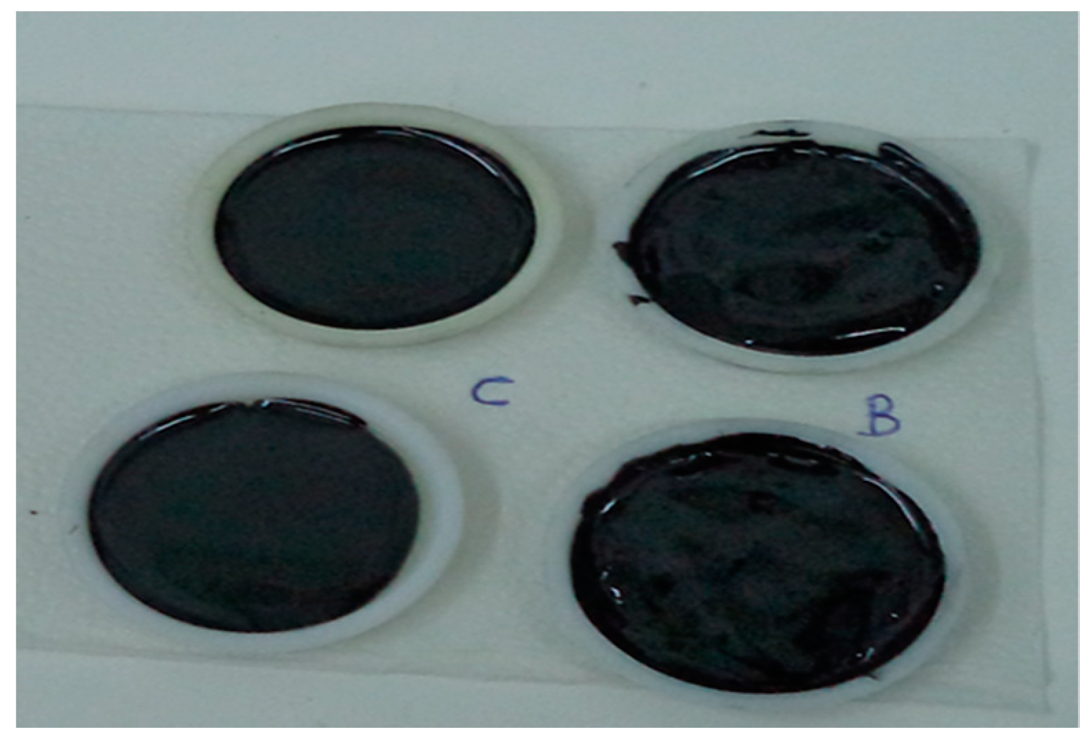
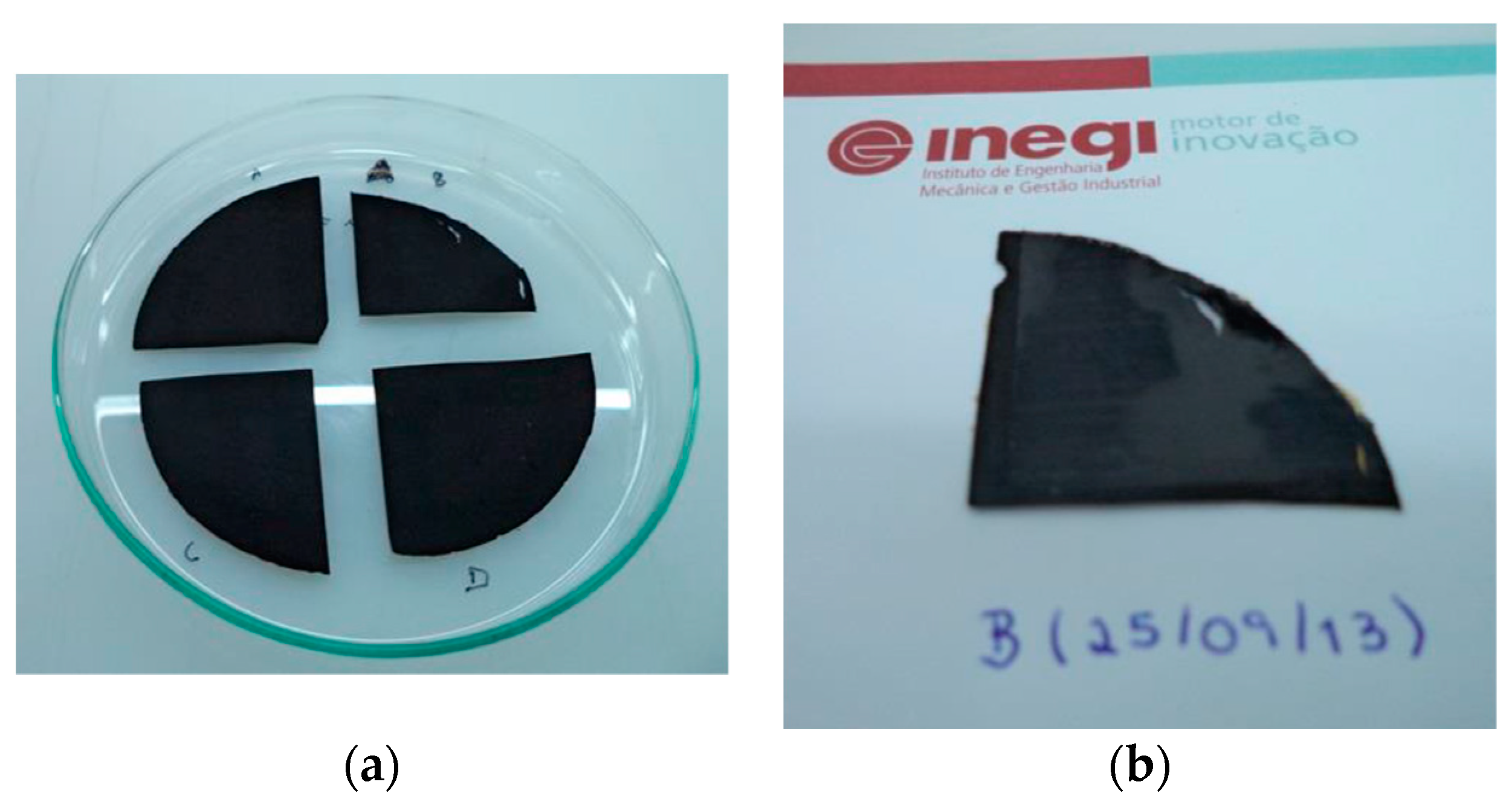
Figure 4 shows pictures of some of graphite and MWCNT resin filled samples inside small plastic moulds, before the curing stage. As one can observed, MWCNT-based samples have presented an extremely rough surface (maintained after curing), which was attributed to the high viscosities of the formulations.
Graphite based samples produced were observed by scanning electronic microscopy (SEM) (FEI Quanta 400FEG ESEM / EDAX Genesis X4M, Thermo fisher Scientific, Hillsboro, OR, USA) for assessing the overall dispersion of the graphite phase in the epoxy matrix. Two representative pictures are shown in Figure 5, where the SEM images show a structure without visible bubbles or fractures near the epoxy–graphite interface. Moreover, a more homogeneous composite structure seems to be obtained for GNP-filled composites when compared with those for GP. This provides evidence for an enhanced distribution of graphite in the composite structure when graphite nanoplatelets are used.
The major conclusion for graphite-filled resins is that they show a very unstable behaviour with the fillers segregating and settling progressively. This was assumed as a major limitation for further use of graphite-filled formulations in the RTM process.
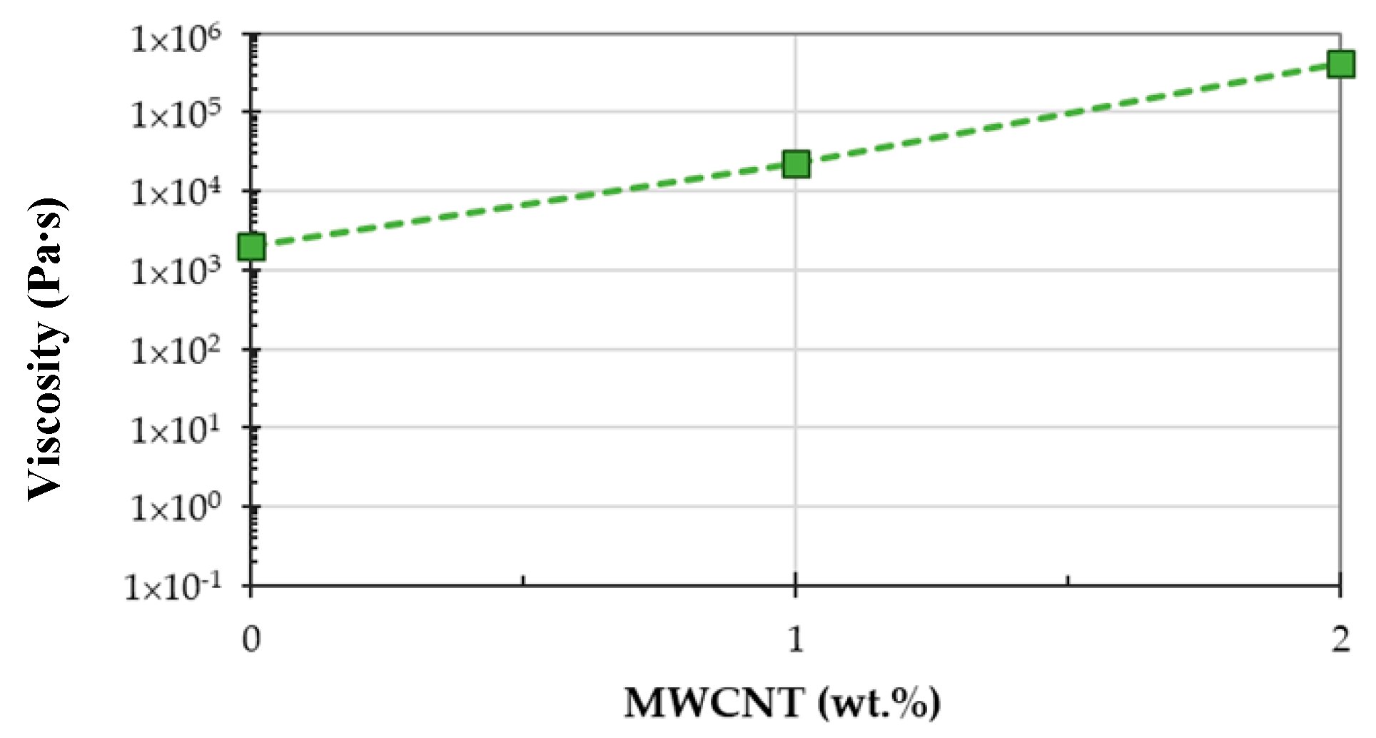
Figure 6 shows that the resin formulation increases its viscosity to about one order of magnitude for each increase of 1 wt.% of MWCNT content in the overall formulation. This very significant increase in the resin viscosity makes it nearly impossible the use of modified resin using RTM technology.
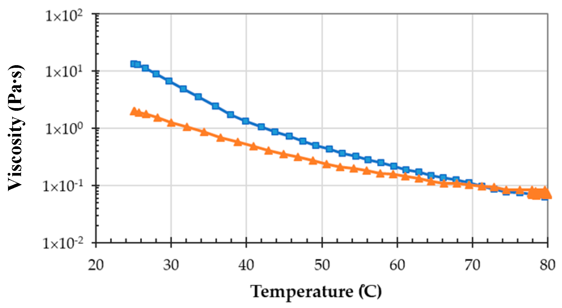
To evaluate the effect of increasing the resin infusion temperature to 80 °C, the viscosity of the resin system was evaluated as a function of the temperature. The results presented in Figure 7 show that the decrease of the viscosity for the curing system is mainly due to the decrease of the LY556 resin viscosity with the temperature. By increasing the infusion temperature from the room temperature to 80 °C, the viscosity decreases in about one order of magnitude, making it suitable for RTM processing. A further isothermal at 80 °C during 20 min (the resin is pre-heated 10 min before infusion) did not show any variation in the viscosity during the testing time, which was expected since gel-time at 80 °C is of approximately 100 min [19].
Table 11 summarizes the obtained viscosity values at 25 and 80 °C for both evaluated systems, showing the significant decrease of the viscosity at the applied infusion temperature.
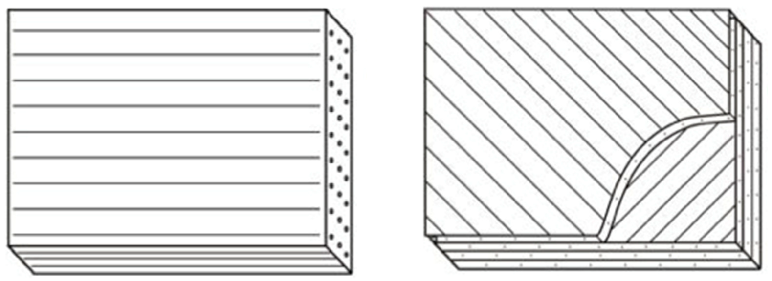
Figure 8 presents photographs of the buckypaper before (a) and after impregnation (b) with the epoxy resin by hand lay-up and further curing in the autoclave (right side).
When the resin is spread manually on the top of buckypaper, it is very difficult to obtain a uniform surface, due to the apparent fragility and permeability of BP. However, the buckypapers could be reasonably impregnated with the resin and the thickness reduced after curing. The CNT content for the buckypaper based samples is in the range of 20–25% (Table 12).
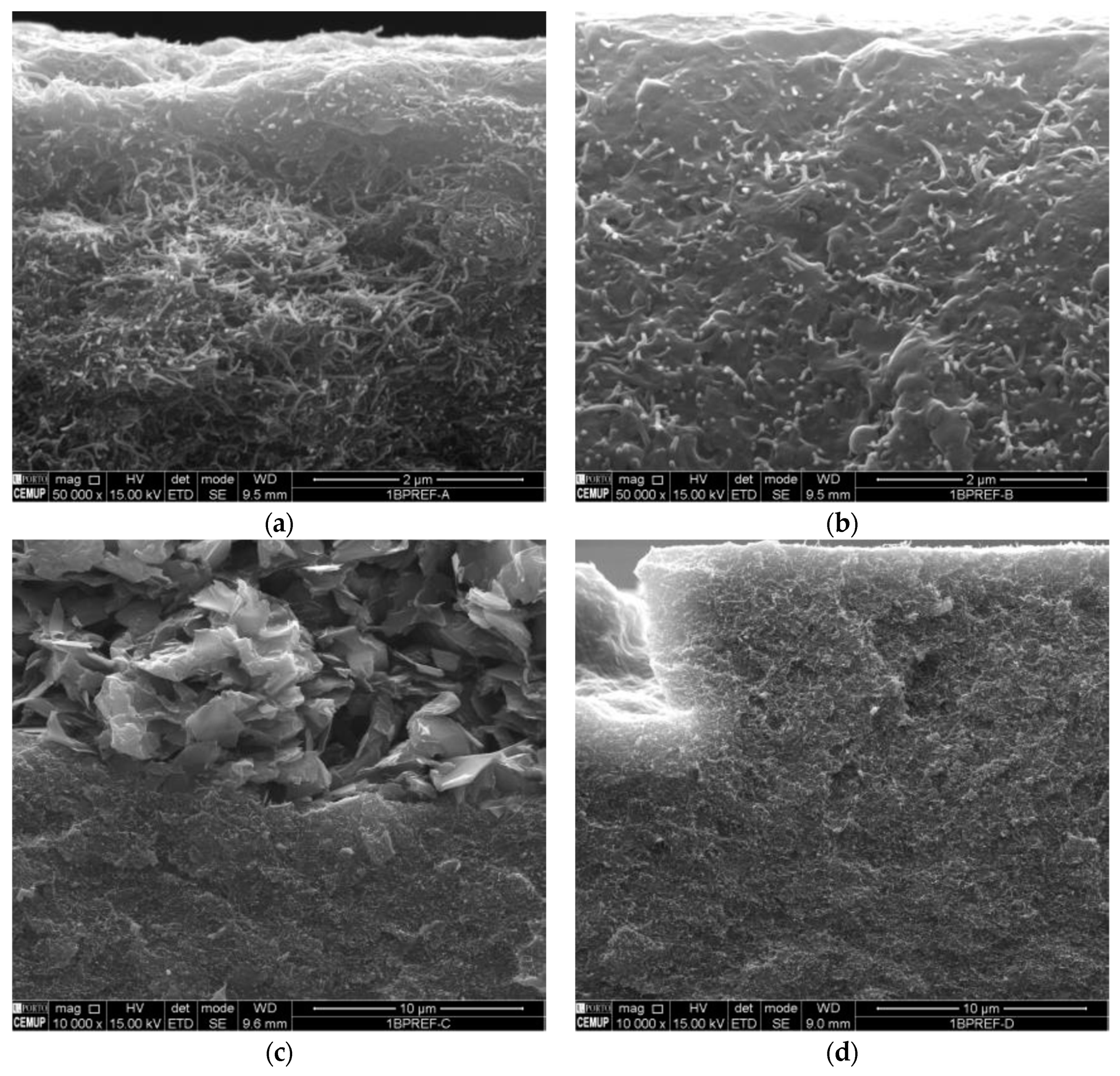
SEM micrographs of buckypaper-based samples are presented in Figure 9. They provide evidence for an enhanced dispersion for the buckypapers impregnated with non-filled epoxy resins. The samples impregnated with modified epoxy resins (BP-3 and BP-4) present a good impregnation, however, phase segregation is evident for the graphite-filled sample.
The main characteristics of the samples with different nanofillers, including the values of thermal diffusivity, are summarized in Table 13. Although changing the type of graphite-filler and its loading does not cause a significant change in the composite specific heat, a significant change is in fact observed in the thermal diffusivity. As one could expect, the thermal diffusivity is enhanced by the increase in the graphite-filler content and by the use of the nano-size graphite.

3.2.2. Carbon Fiber-Reinforced Polymer (CFRP) Samples

For manufacturing CFRP sample plates, three impregnation processes were tested. Initially, due to material availability issues and for reference purposes, PAN-based carbon fibers were used to prepare the CFRP-based panels. Different processing parameters were evaluated, such as the fibers’ nature, curing pressure, number of layers and apparatuses used.
Further manufacturing runs were performed, incorporating CNT buckypapers with pitch fibers, aiming to increase the thermal conductivity.
Table 14 presents the process conditions and observations taken during the manufacturing of CFRP samples. The pitch fibers were handled and cut with careful attention. The resin was prepared by manual mixing and then put inside an oven at 80 °C, during 10 min. This allowed the viscosity of the resin to be significantly decreased, easing the infusion process. The infusion vacuum pressure pushes slowly the resin across pitch fibers.
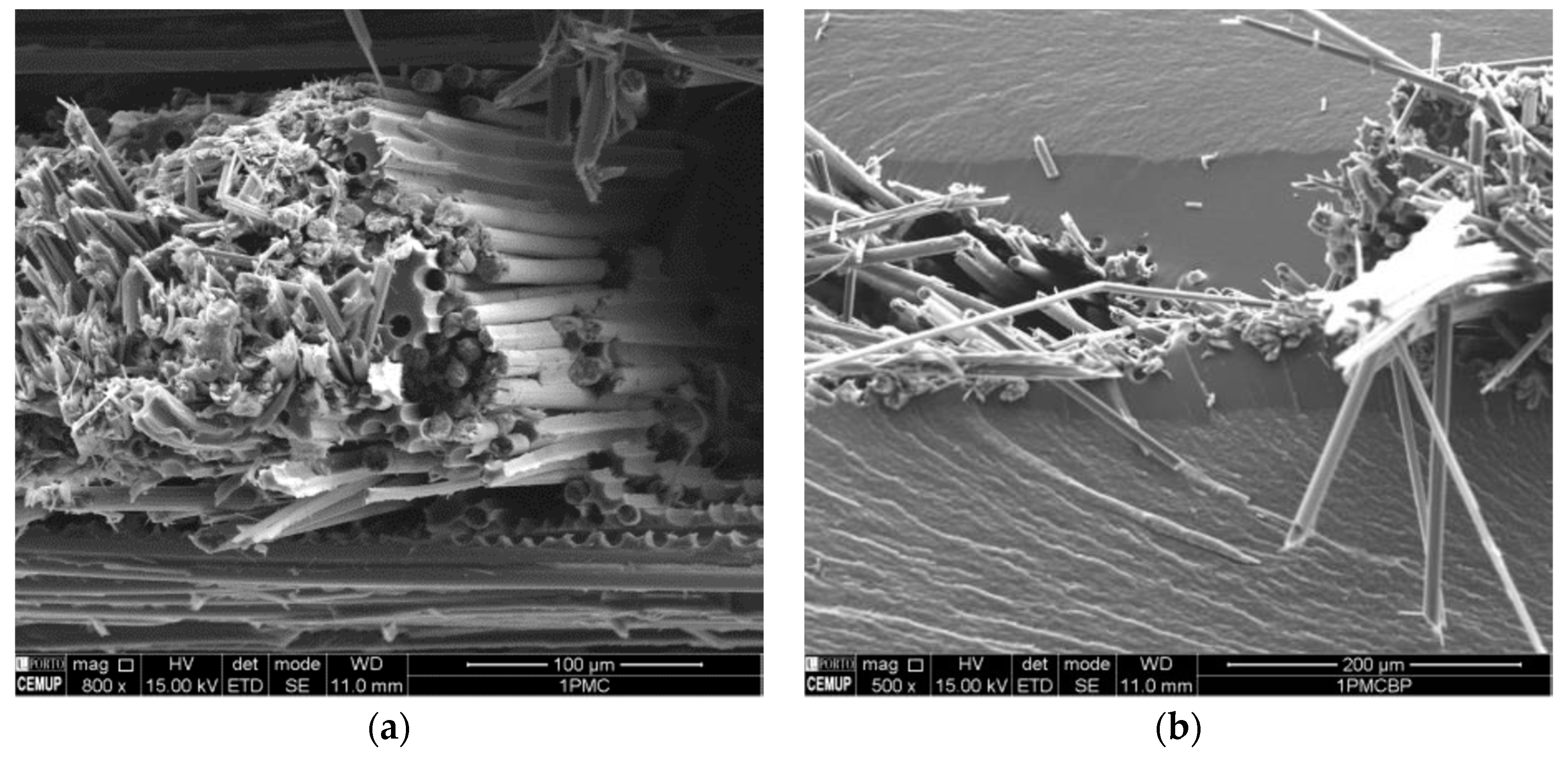
SEM images of CFRP plates PiCF-3b and PiCFBP-3b are provided in Figure 10. Although the image provides some evidence for the fragility of the fibers, the existence of resin between fiber filaments is indicative for the good impregnation. The sample with the buckypaper (PiCFBP-3b) provides evidence for the resin filling of the buckypaper phase.
Based on the thermal diffusivity and conductivity obtained values, especially considering that significant improvements were obtained with high compaction pressures, a material configuration based on K13D2U-carbon fibers and epoxy-based resin system was selected, without the inclusion of any nanomaterial that, not only would make difficult the implementation of the RTM process, but also would not lead to significant improvements in through-thickness conductivity. Three CFRP panels were produced for complete characterization before breadboard manufacturing (Table 15).
For Panel C (±45° lay-up), a 0°/90° lay-up of 16,210 mm-side squared plies was manufactured. From this lay-up, a rectangle at ±45° orientation with maximum dimensions of 200 mm × 100 mm for mechanical testing was obtained, but smaller specimens could be taken from the remaining panel for other testing. A total of 10 carbon fiber fabric layers were used to achieved an approximate thickness of 2 mm in the unidirectional panels (Panels A and B).
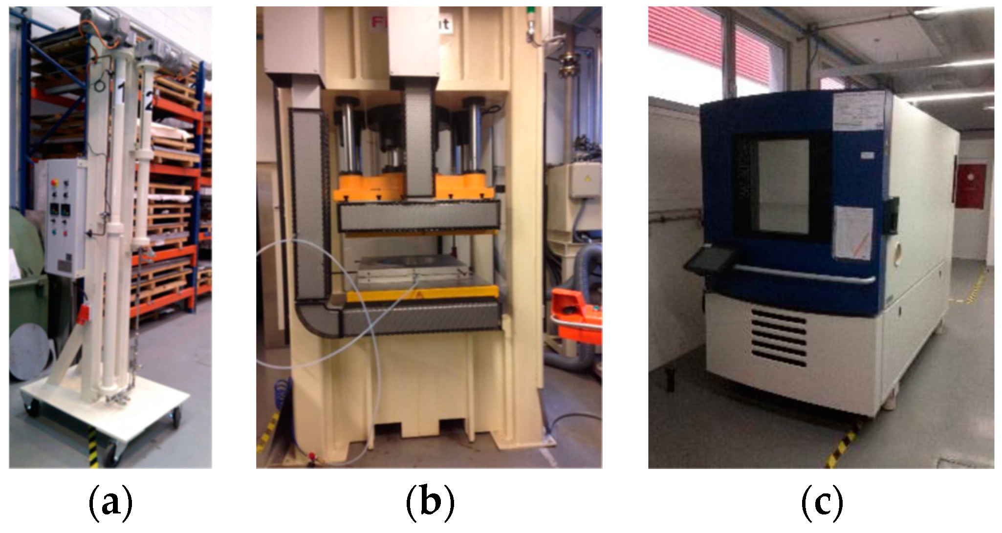
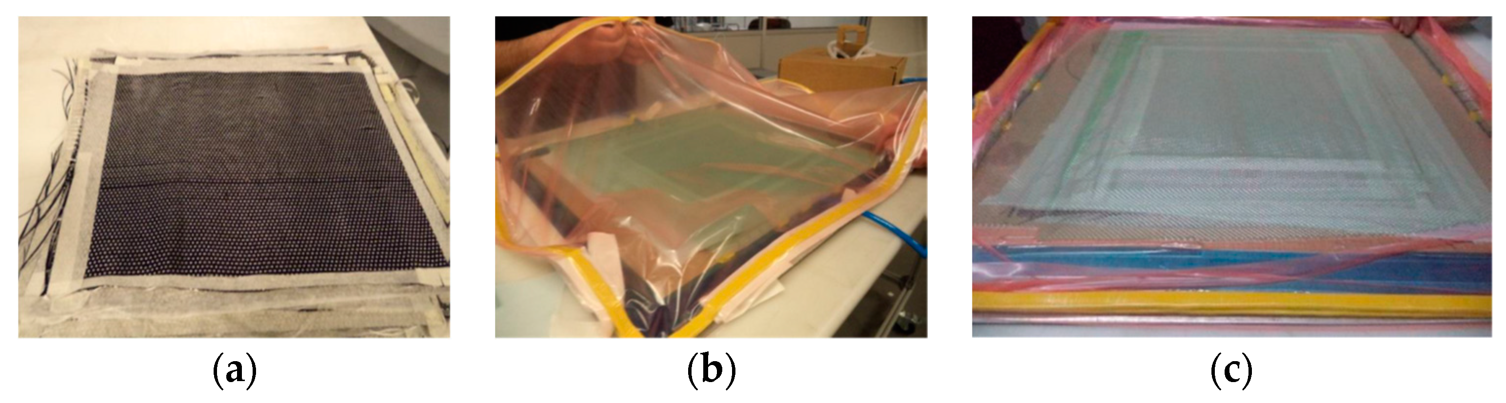
Figure 11 shows some representative images of the manufacturing process, which can be summarized in the following steps. Initially, each fabric layer is carefully handled and correctly placed to guarantee an accurate lay-up. The lay-up is then placed into a flat mould and further sealed in a vacuum bag system. Afterwards, the system is subjected to vacuum to guarantee a homogeneous vacuum pressure inside the vacuum bag. The materials are then placed inside the hot-press which is, pre-heated to 80 °C, while the resin is heated to 80 °C for 10 min and then infused with the application of the vacuum. After the infusion process, the press is closed at the defined pressure and the temperature cycles are initiated. The panels were demoulded the day after.
Lower magnification images of the produced CFRP panels (A, B, C) were taken with a light optical microscope (LOM) (Olympus PMG3 equipped with an Olympus Dp-12 camera) (Tokyo, Japan) to provide an overview of their structure. 
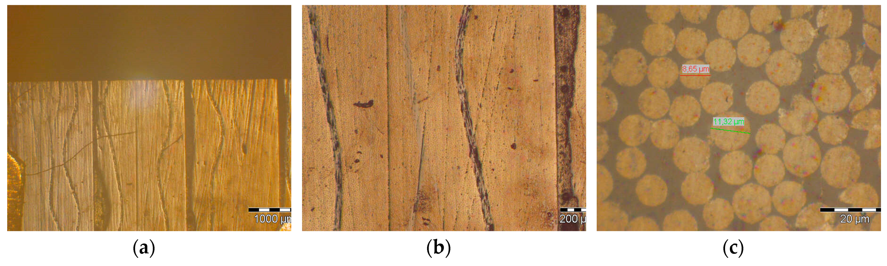
Figure 12 presents LOM images of a stack produced with 4 samples from Panel A. The darker 100–200 µm layer (aligned with the fibers direction) is due to the use of structural adhesive to produce the stacks. Figure 12a indicates a well-defined orientation of the carbon fiber and reasonably uniform CFRP samples. Figure 12b shows a closer inspection of a thinner resin layer that can result from compaction defects during their processing, which may also be associated with some defects found in the manufactured pitch-based fabrics. Finally, Figure 12c was taken at the top surface and shows the fibers perfectly aligned in the same direction.
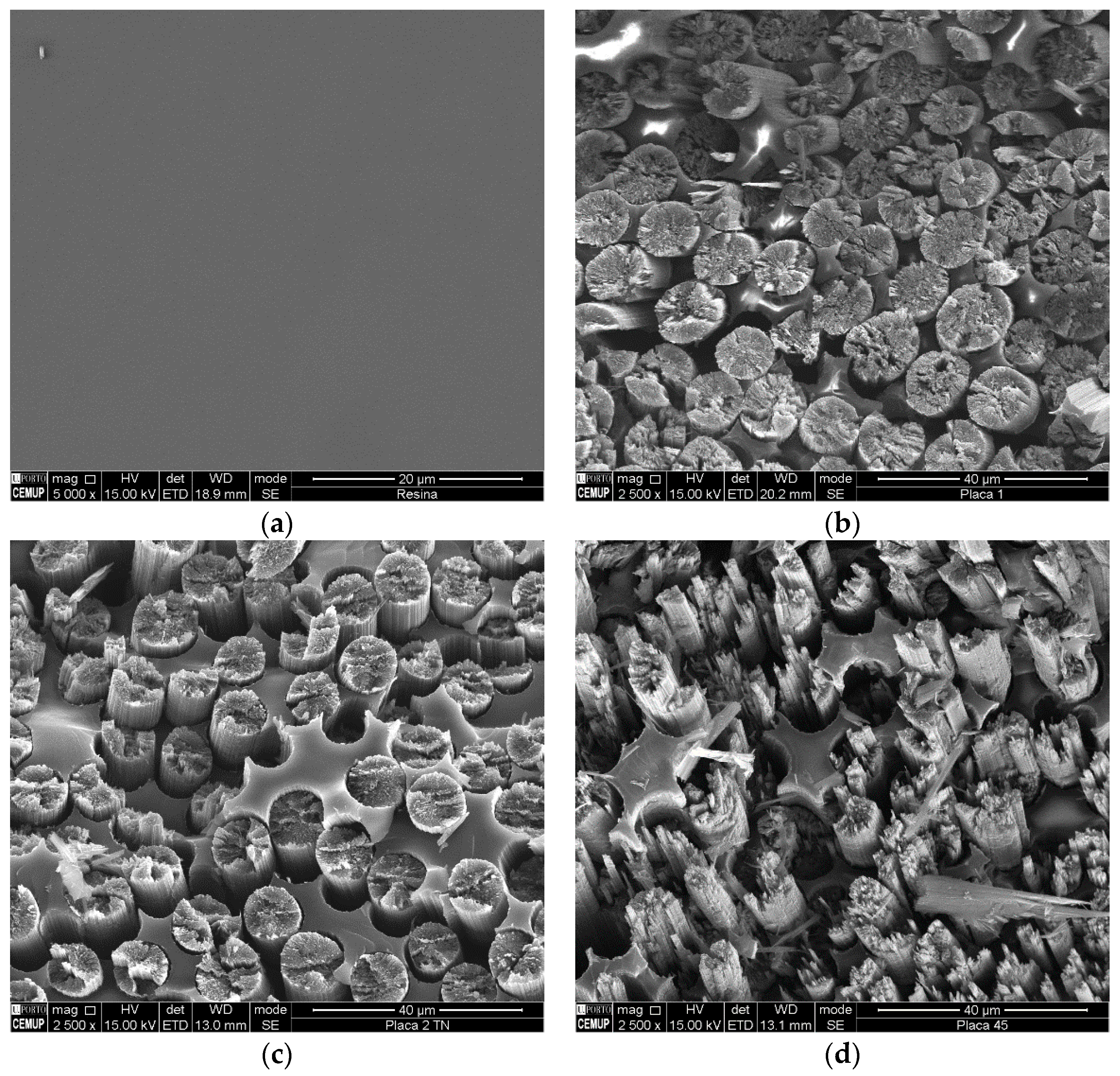
A closer inspection of the fibers and the quality of their coating with the epoxy-based resin can be provided through SEM (Figure 13). For comparative purposes, Figure 13a provides a micrograph for the blank sample (only resin). The micrographs for the CFRP panels shows that the fibers are well aligned in a single direction and provide evidence for a well-coating of the fibers. In addition, these micrographs also suggest the existence of a significant number of contact points between fibers, which may be responsible for an increase in the thermal conductivity in the through thickness direction when compared to a pure series model. Table 16 presents a summary of the structural observation of the samples.

3.2.3. Breadboard Manufacturing and Testing

Taking into concern the electronic box requirements (Table 8), the following considerations were further used for the preliminary breadboard design:
  • Box with no undercuts or chamfers for the accommodation of the PCBs;
  • Round edges with a minimum radius of 8 mm to allow smooth bending of fibers;
  • Single thin wall technology, no sandwich structure for ease of manufacturing and good thermal control;
  • The initial aluminum design was split up into several components for manufacturing reasons;
  • The mechanical interface PCB to the frame is solved by laminating brackets into the frame on which the PCB’s can be screwed;
  • A focus is put on modularity of the geometry and modularity.
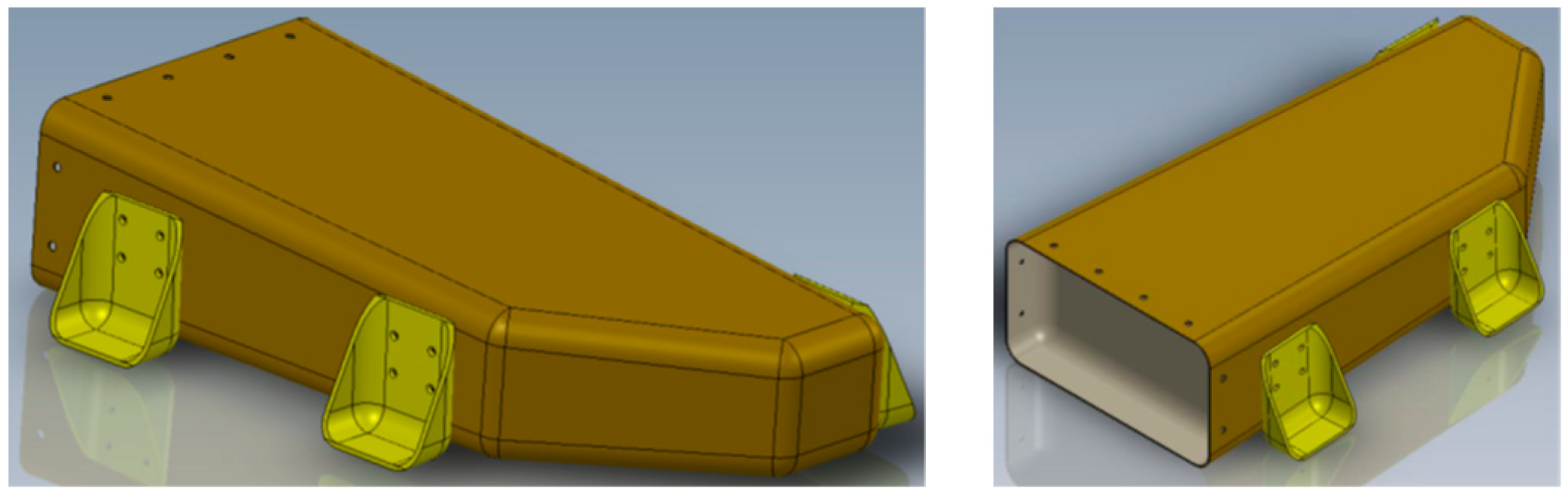
Figure 14 presents the breadboard assembly which resulted from the preliminary design. This design considered four main parts: PCB-frames, housing, lid, and feet. In the preliminary design, the PCB-frames were considered to be made in CFRP, but due to the difficulty to manufacture these CFRP structures, at a later stage it was decided to use aluminum stiffeners. The lid assembly would ensure good electrical contact and avoid electromagnetic poor joint. The feet would be glued to the housing and then bolted to the panel.
To further guarantee a reduction of the weight, while maintaining the same level of thermal and mechanical performance, the following aspects were considered to proceed for the detailed design:
  • Reduction of the areal weight of the K13D2U-based UD (unidirectional) fabric was expected to be able to provide enhanced mechanical performance at lower mass;
  • Optimization of the mass through improved design of bolted joints, PCB I/F inserts, and PCB support structures, which was also expected to be enhanced by lower areal weight fabric.
The draping of the carbon fiber fabrics into the desired lay-up was recognized as a critical phase of the process. The very low areal weight of the fabric, combined with the high susceptibility for breaking, makes its handling a difficult task. Figure 15 presents some photographs of the initial draping tests that were carried out, highlighting the difficulty in handling and positioning the fabrics.
From these initial trials, two important factors were evident:
  • The importance of creating flat patterns to pre-cut the fabric into the desired shape and to support them with paper tape;
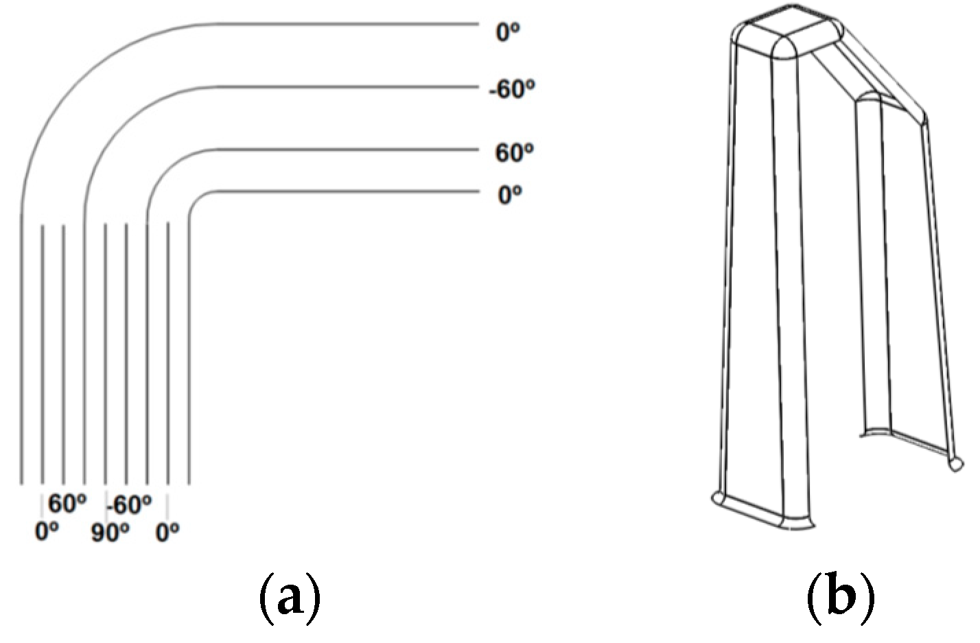
  • The impossibility of using a single fabric to go from the top surface towards the cut-corner of the box, due to the need for increased width of the fabric at the cut-corner.
The second factor has created the need to divide the breadboard box into two parts for draping: one covering the bottom surface, the flat wall and the top surface, and the other part covering the side wall with the cut-corner and the wall opposite to lid. To guarantee sufficient structural performance of the box, these two parts need to be overlapped at some point. Considering the ease of draping and the required structural stability, this overlapping was carried out at the top surface. Based on the breadboard detailed design activity, the top and bottom surface was manufactured with 4 layers of fabric, whereas all the walls possess 9 layers. This means that 5 additional layers were placed between the 4 layers used for the bottom and top surfaces. These additional layers were placed from the top of the mould covering all the side walls, using a pre-cut fabric for draping as shown in Figure 16.
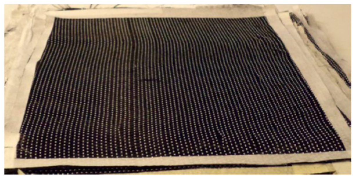
The fabric was cut to the desired size with the help of tape support (Figure 17) to guarantee the stability of the part on handling, due to the high susceptibility for damaging on handling of the pitch fibers.
After the definition of the critical factors in terms of component production, the manufacturing steps of the CFRP electronic box were defined. The first steps were to fill the tanks with resin and hardener with accelerator mixture, respectively, and then preheat the resin tank to 50 °C. After fiber trimming, cleaning and preparation of the manufacturing moulds, the fibers were applied in the mould. The resin injection pipe was connected to the mould and the press closed with different pressures: 31.8, 15.4 and 14.2 tons for box, lid and feet moulds, respectively. The heating electrical resistances and temperature controller were connected in the pre-heated tank, in the mould, and in the mixing zone. The resin injection was then started, under a pressure of 10 bar, and stopped when the resin exits the mould through the vacuum gate. The moulds were then heated to 120 °C during 2 h. The materials were allowed to cool down to 45 °C and before the post-curing process (2 h at 180 °C), the product was trimmed to the desired shape.
This manufacturing process required control of several processing parameters, such as the injection pressure and temperatures profile. The injection pressure was continuously monitored through the process with the manual registry and re-adjusted, when necessary, to guarantee that the resin was injected at the same pressure during the entire process. The temperature was controlled at several critical points, considering the high sensitivity of the resin components and of the process itself to this parameter. The critical temperature measuring points are the storage (feeding) system, mixing zone, and moulds.
Based on simulation processing models and on critical processing parameters, the manufacturing conditions were established and are summarized in Table 17.
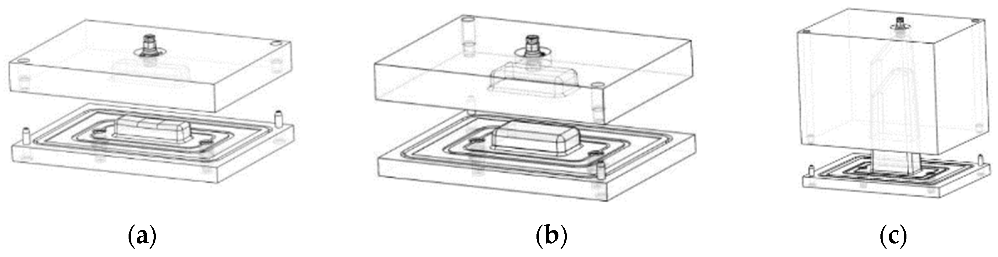
The moulds were designed based on the defined geometry of each CFRP component (box, lid, and feet) and considered to be five key parameters of the process: injection gates, runner, pinch-off, sealing, and vents. Figure 18 shows the 3D models of the moulds required to manufacture the three CFRP components. Photographs of each of the manufactured moulds and of their assembly are shown in Figure 19.
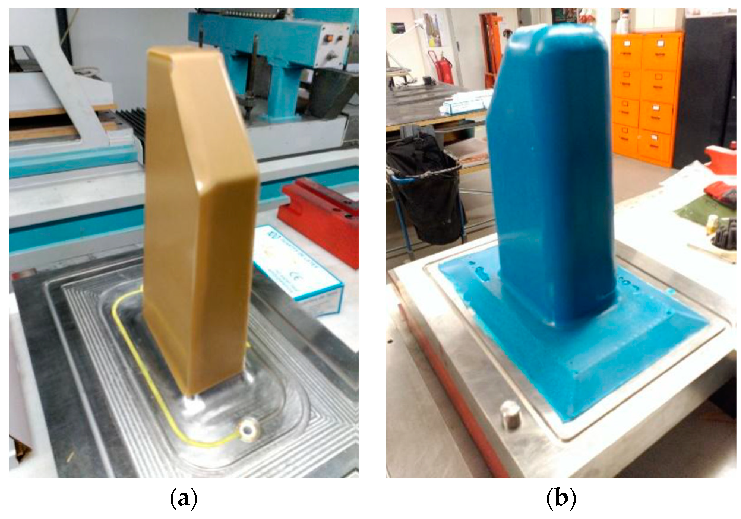
The additional silicone mould for the box manufacturing was produced (Figure 20), using calibrated wax to define the target spacing gap between this new mould component and the male mould.
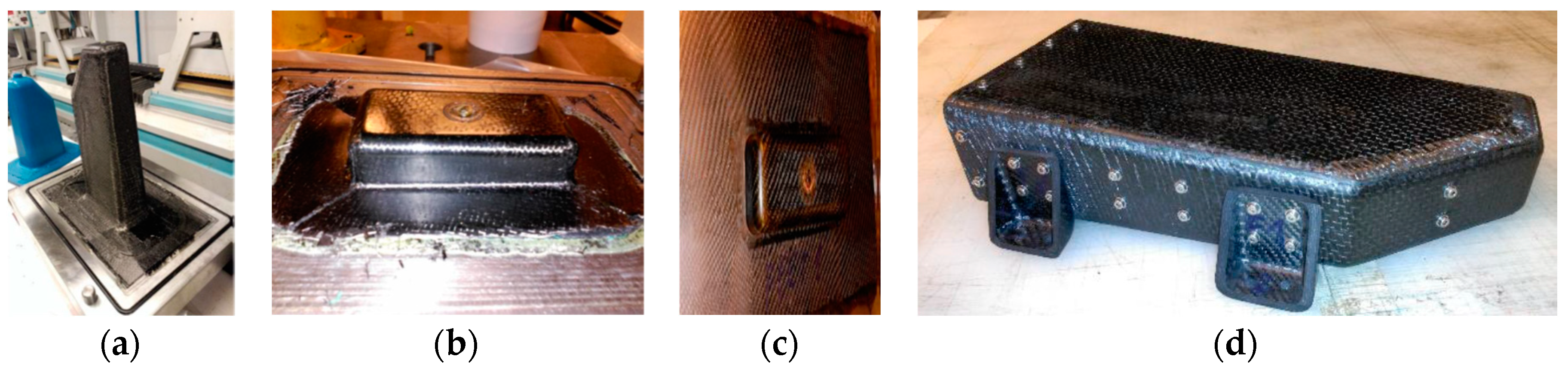
The final manufactured parts, as well as of the assembled breadboard, are shown in Figure 21.
To finally demonstrate the thermal performance of the assembled electronic box, two thermal balance tests were performed. In the first test, a maximum temperature of 100 °C was obtained in the PCBs, which was significantly higher than that predicted in the design. This was associated with the poor interface between the PCBs and stiffener, which was not able to transfer properly the heat to the stiffener. To improve this conductivity between electrical resistances, PCB and stiffener, steel weights (that simulate electrical components of the PCB) were added on the top of the PCB and a copper plate was positioned between the PCB and stiffener to transmit more efficiently the heat in the PCB to the stiffener (Figure 22).
With the improved PCBs design, the maximum temperature obtained was 92 °C, which, although being above what was predicted by the design, is closer to an acceptance range. Table 18 presents a summary of the thermal balance test results obtained in the two tests (Test1—original configuration; Test 2—improved PCBs design).
Table 19 compares the maximum temperature that was obtained for the electronic housing concept using a CFRP and aluminium concept, showing that with the current design a gain in about 3.5 °C could be obtained.
The thermal tests included a thermal cycling (with the following cycle: RT − 60 °C − –40 °C − 60 °C − –40 °C − RT), which showed no visible damage in the breadboard (Figure 23).
Based on thermal sensitivity analysis, this thermal performance is highly dependent on the efficiency of thermal contact areas and the increased temperature seems to be in agreement with the simulations that were considered inferior contact areas. This is a critical aspect to be considered in future development activities.
The final mass of the breadboard was compared with the values obtained in the design and with the requirements in Table 20, providing evidence of compliance with the mass requirement, if one considers that more than 20% of mass is reduced, excluding the non-variable item of the reference application, the PCBs mass. Moreover, one should note that the manufactured feet may be overperforming due to the higher mass obtained, as a consequence of a lower thickness considered during the design phase. It is, thus, expected that a further reduction of approximately 40 g can be obtained. When compared to the design, the lower mass obtained for the box and the greater for the lid can be associated, respectively, with higher and lower fiber volume fractions obtained. This was also already expected, due to lower than expected thickness at the box and excessive gap correction in the lid moulds.
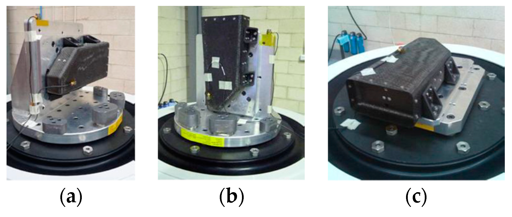
The mechanical performance of the breadboard was evaluated in a shaker table according to the parameters defined in the requirements. Figure 24 shows the breadboard mounted for testing in the three different directions and Table 21 provides a summary for the mechanical test results that were obtained.
Due to the lid manufacturing process difficulties at the corners, a very small fracture was present in one of the lid corners. This fracture was found to propagate slightly with the progress of the mechanical testing, but it should be stressed that still no failure was observed.
Overall, the mechanical test results were shown to be compliant with the breadboard requirements, providing evidence for successful mechanical design and manufacturing and assembly processes.

4. Conclusions

The final performance of the breadboard indicated that it is possible to have a significant mass reduction through the use of pitch-based CFRP material with high fiber volume contents for the production of thermally conductive CFRP electronic boxes. In fact, a mass reduction of 23% was obtained when compared to an equivalent aluminum housing, but further reduction can be expected due to oversizing of the feet-supporting structures and the potential to optimize the breadboard design. Moreover, the proposed design and the manufactured breadboard showed good compliance with mechanical and electrical requirements for spacecraft structures.
This study showed the feasibility to obtain thermally conductive CFRP materials using an out-of-autoclave RTM process with demanding characteristics typically obtained in autoclave processes, such as high fiber volume fraction, while being able to provide significant mass savings, when compared to equivalent aluminum housings. These mass savings can represent a cost saving of approximately 50% for 10 unit series.
However, for future development of these technologies and to make it possible to fully achieve the objectives, some identified issues need to be addressed.
Considering the low through-thickness conductivity improvements and the resulting increased difficulties for RTM processing when the resin is modified with nanomaterials (in addition to the current low level of maturity of such technologies), the design should be focused in the in-plane conductivity of the carbon fibers.
Considering the extremely high price of the thermally conductivity pitch-based carbon fibers, lay-up and draping methodologies should be optimized to minimize the generation of wastes.

Author Contributions

M.M. was involved in materials selection, development and testing; R.G. lead the process simulation and manufacturing of the CFRP electronic box; L.P. was responsible for the CFRP breadboard testing. C.P. was involved in the definition of project approach and initial stage developments. O.R. was responsible for the electronic box design. D.T. was responsible for the project concept and monitoring. N.C. was responsible for technical approach integration. N.R. was responsible for technical coordination.

Funding

This research was funded by the European Space Agency (ESA), under the contract AO/1-7543/12/NL/CP, in the frame of the project “Thermally Conductive RTM CFRP”.

Acknowledgments

Authors are grateful to financial support from European Space Agency (ESA), under the contract AO/1-7543/12/NL/CP, in the frame of the project “Thermally Conductive RTM CFRP”.

Conflicts of Interest

The authors declare no conflicts of interest.

References

  1. Pereira, C.; Silva, S.I.; Rocha, N.; Vasques, C. Manufacturing Process Report; RTMEBOX-INE-TN080, Thermally Conductive RTM CFRP; ESA contract no. 4000107706/13/NL/CP; INEGI—Institute of Mechanical Engineering and Industrial Management: Porto, Portugal, May 2014. [Google Scholar]
  2. Katajisto, H.; Brander, T.; Wallin, M. Structural and Thermal Analysis of Carbon Composite Electronics Housing for a Satellite. In Proceedings of the NAFEMS Seminar—Component and System Analysis Using Numerical Simulation Techniques—FEA, CFD, MBS, Gothenburg, Sweden, 23–24 November 2005. [Google Scholar]
  3. Vanaja, A.; Jayasankar, S.; PAdmavathi, T.; Jyotsna, K.M.; Madhusudhana, V.; Balaji, G. Light Weight Conductive Polymer Composites Enclosure for Avionics. Int. J. Mech. Prod. Eng. 2007, 5, 57–61. [Google Scholar]
  4. Finckenor, M.M.; Groh, K.K. Space Environmental Effects, a Researcher´s Guide to International Space Station, NASA (2015). Available online: https://www.nasa.gov/sites/default/files/files/NP-2015-03-015-JSC_Space_Environment-ISS-Mini-Book-2015-508.pdf (accessed on 1 October 2018).
  5. Composites Materials. Available online: https://commons.wikimedia.org/wiki/File:Composites_Materials.png (accessed on 5 November 2018).
  6. Gaier, J.R.; YoderVandenberg, Y.; Berkebile, S.; Stueben, H.; Balagadde, F. The electrical and thermal conductivity of woven pristine and intercalated graphite fiber–polymer composites. Carbon 2003, 41, 2187–2193. [Google Scholar] [CrossRef] [Green Version]
  7. Spacecraft EMI Control in the Presence of Composite Materials: Summary Report; SECC-HPS-RP-0001, ESA Contract 18985/05/NL/JA; HPS GmbH: München, Germany, 2007.
  8. Leininger, M.; Thurecht, F.; Pfeiffer, E.; Ruddle, A.R. Spacecraft EMI Control in the Presence of Composite Materials: Manufacturing Report and Photographs; SECC-INV-TN-0142, Technical Note 14-2; HPS—High Performance Structures: München, Germany, June 20.
  9. Silva, S.; Pereira, C.; Rocha, N. D3.1—1st Progress Report; WP3—Pre-impregnated materials development, EUCARBON project, Project ID: 284500, Funded under: FP7-SPACE; INEGI—Institute of Mechanical Engineering and Industrial Management: Porto, Portugal, June 2012. [Google Scholar]
  10. Han, S.; Chung, D.D.L. Increasing the through-thickness thermal conductivity of carbon fiber polymer-matrix composite by curing pressure increase and filler incorporation. Compos. Sci. Technol. 2011, 71, 1944–1952. [Google Scholar] [CrossRef]
  11. Naito, K.; Yang, J.-M.; Xu, Y.; Kagawa, Y. Enhancing the thermal conductivity of polyacrylonitrile- and pitch-based carbon fibers by grafting carbon nanotubes on them. Carbon 2010, 48, 1849–1857. [Google Scholar] [CrossRef]
  12. Pilling, M.W.; Yates, B.; Black, M.A.; Tattersall, P. The thermal conductivity of carbon fibre-reinforced composites. J. Mater. Sci. 1979, 14, 1326–1338. [Google Scholar] [CrossRef]
  13. Rolfes, R. Transverse thermal conductivity of CFRP laminates: A numerical and experimental validation of approximation formulae. Compos. Sci. Technol. 1995, 54, 45–54. [Google Scholar] [CrossRef]
  14. Atxaga, G.; Marcos, J. AED Executive Summary, Advanced Equipment Design. ESTEC Co.: No.16725/02/NL/CK. 2005. Available online: http://gsp.esa.int/documents/10192/43064675/C16725-C-ExS.pdf/8f07df22-9a29-4174-916f-9b62bc530cc1 (accessed on 1 July 2018).
  15. Thurecht, F.; Pfeiffer, E.; Ihle, A.; Marioli-Riga, Z. Space RTM: Final Report, Synthesis; SRTM-HAI-TN10.2; HAI, H2009; HPS—High Performance Structures: München, Germany, May 2007. [Google Scholar]
  16. ASTM. Standard Test Method for Thermal Diffusivity by the Flash Method; ASTM E 1461-11; ASTM: West Conshohocken, PA, USA, 2011. [Google Scholar]
  17. ASTM. Standard Test Method for Determining Specific Heat Capacity by Differential Scanning Calorimetry; ASTM E1269-99; ASTM: West Conshohocken, PA, USA, 2001. [Google Scholar]
  18. Sousa, A.; Silva, T.; Rebelo, D.; Martins, R.; Pinto, I. EVO-RTMEBOX-RP-010-1, Dummy Boards Design; EVOLEO Technologies: Maia, Portugal, 2014 December. [Google Scholar]
  19. Pereira, C.; Silva, S.I.; Rocha, N.; Vasques, C. RTMEBOX-INE-TN080, Issue 2, Manufacturing Process Report; Thermally Conductive RTM CFRP, ESA contract no. 4000107706/13/NL/CP; INEGI—Institute of Mechanical Engineering and Industrial Management: Porto, Portugal, April 2014. [Google Scholar]
Figure 1. Representation of composite materials, showing the reinforcement fibers in different directions [5].
Fibers 06 00092 g001
Figure 2. (a) Injection equipment; (b) press equipment; (c) climatic chamber.
Fibers 06 00092 g002
Figure 3. Electronic box design.
Fibers 06 00092 g003
Figure 4. Photos of the epoxy resin filled samples (C: with graphite powder; B: with MWCNT).
Fibers 06 00092 g004
Figure 5. Scanning electron microscope (SEM) images (through thickness) of the samples. (a) Resin with 20% graphite powder (GP); (b) resin with 20% graphite nanoplatelets (GNP).
Fibers 06 00092 g005
Figure 6. Resin system viscosity containing different amounts of MWCNT.
Fibers 06 00092 g006
Figure 7. Viscosity of the resin and resin system (plus hardener) as a function of the temperature, at a shear rate of 1.25 s−1.
Fibers 06 00092 g007
Figure 8. Photos of the buckypaper before (a) and after (b) impregnation and curing.
Fibers 06 00092 g008
Figure 9. SEM images (through thickness) of the CNT-BP samples: (a) BP-1, (b) BP-2, (c) BP-3, (d) BP-4.
Fibers 06 00092 g009
Figure 10. SEM images (through thickness) of samples PiCF-3b (a) and PICFBP-3 (b).
Fibers 06 00092 g010
Figure 11. Photographs of technological samples manufacturing (a) applied vacuum; (b) resin transfer moulding (RTM) system inside the hot-press; (c) closed hot press.
Fibers 06 00092 g011
Figure 12. Light optical microscope (LOM) images of stacks of Panel A at different magnifications (a) 23×, (b) 75×, (c) 1500×.
Fibers 06 00092 g012
Figure 13. SEM micrographs of technological samples (a) resin (b) panel A (c) panel B (d) Panel C.
Fibers 06 00092 g013
Figure 14. (a) Breadboard assembly, result of the preliminary design (b) Front view of the breadboard (without the lid) with detail of the CFRP-based PCB (printed circuit board)-frames.
Fibers 06 00092 g014
Figure 15. Initial draping tests.
Fibers 06 00092 g015
Figure 16. (a) Positioning of the additional carbon fabric layers; (b) pre-cut fabric for draping the additional 5 layers for the side walls.
Fibers 06 00092 g016
Figure 17. Fabric pre-cut to size with tape paper support.
Fibers 06 00092 g017
Figure 18. 3D models of the moulds for CFRP breadboard components manufacturing (a) feet (b) lid (c) box.
Fibers 06 00092 g018
Figure 19. Manufactured moulds (a) breadboard female (b) breadboard male (c) breadboard assembly (d) lid female (e) lid male (f) lid assembly (g) feet female (h) feet male (i) feet assembly.
Fibers 06 00092 g019
Figure 20. Silicone mould manufacturing. (a): Calibrated wax applied to the mould.; (b): Cured silicon rubber.
Fibers 06 00092 g020
Figure 21. Photographs of final CFRP parts (a) box (b) lid (c) feet (d) breadboard.
Fibers 06 00092 g021
Figure 22. New PCB design for improved heat transfer from the PCB to the stiffener (a) top view (b) bottom view.
Fibers 06 00092 g022
Figure 23. Breadboard inside the vacuum chamber fully integrated for thermal balance.
Fibers 06 00092 g023
Figure 24. Breadboard mounted on the shaker table for testing in different directions (a) X direction (b) Y direction (c) Z direction.
Fibers 06 00092 g024
Table 1. Comparison of polyacrylonitrile (PAN) and pitch-based carbon fibers data values from [11,12,13].
PropertyPAN-Based FiberPitch-Based Fiber
Morphology Fibers 06 00092 i001 Fibers 06 00092 i002
Density (g/cm3) 1.73–1.932.10–2.19
Axial Thermal conductivity (W/mK)14–100320–800
Radial Thermal conductivity (W/mK)0.5–100.5–10
Table 2. Thermal conductivity of different fillers.
FillerEpoxy ResinCarbon nanotubes (CNTs)Carbon nanofibers (CNFs)Carbon BlackCNT BuckypaperGrapheneGraphiteCopperBorn NitrideAluminiumAluminum OxideAluminum NitrideAluminun, Pure
Thermal conductivity (W/mK)0.172000–600019506–17415–455300100–40048330–40024020–29180–200200
Table 3. Properties of carbon fibers used.
PropertyFiber
K13D2UT300
Tensile Strength (MPa)3.73.5
Tensile Modulus (GPa)935230
Density (g/cm3)2.21.8
Electrical Resistivity (·.m)1.5 × 10−61.7 × 10−5
Thermal Conductivity (W/mK)80010.4
Sizing (%)20.7; 1
Filament Diameter (μm)117
Filament Number20003000
TwistuntwistedTwisted, untwisted, or never twisted
Carbon Content (%)>9993
Ultimate Elongation (%)0.41.5
Table 4. Nominal properties of carbon fiber fabrics used.
PropertyK13D2UT300
Warp3.45 thr/cm12.5 pc(s)/25 mm
Weft1.00 thr/cm12.5 pc(s)/25 mm
Warp raw-materialK13D2U 365 texT300–3000
Weft raw-materialEC 9 34 texT300–3000
Weave patternPlain weavePlain weave
Areal weight130 g/m2200 g/m2
Maximum width80 cm100 cm
Table 5. Properties of the epoxy resin system used.
ComponentTypewt.%vol%Viscosity (Pa·s, 25 °C)
LY556Epoxy resin10010010,000–12,000
HY906Anhydride hardener95921–1.25
DY070Imidazole accelerator0.50.60.95–1.05
Table 6. Fillers characteristics and suppliers.
ComponentCharacteristicsSupplier
Buckypaper (CNT Skeleton)Carboxylate MWCNT; n-hexane treated; paper form with random oriented MWCNT; thickness = 250,500 μm.Future Carbon GmbH
Multi-walled carbon nanotubes (MWCNT)MWCNT Masterbatch in LY556 resin at 2 wt.%Future Carbon GmbH
GraphiteGraphite powder (GP): D10: 1–5 μm; D50–3 μm; D90–6 μm Graphite nanoplatelets (GNP): 200–800 nm Purity higher than 98%PlasmaChem
Table 7. Typical properties of Sigraflex foil.
PropertyValue
TypeFlexible foil
Chemical compositionExpanded natural graphite
AdhesiveSelf adhesive
Thickness (mm)0.1–1
Density (g/cm3)0.7–1.3
Thermal conductivity (W/mK)180–200 (in plane), 4–6 (perpendicular)
Thermal stability (°C)−250 to 3000
Tensile Strength (GPa)≥4
Elongation at break (%)1
OutgassingTML 0.92%, RML 0.88%, CVCM 0.01%
Table 8. Electronic box requirements.
RequirementSpecificationValue
Mass20% lower than of the equivalent aluminum solution≤1607 g
volume equal to reference housing
SizeHousing size263 × 132 × 50 mm³
Thermal conductivityHeat transfer capabilitiesin-plane ≥ 150 W/mK
through-thickness ≥ 10 W/mK
Service temperaturesTemperature range for materials−120 °C–+120 °C
Operation requirements qualification−40 °C–+60 °C
OutgassingCompatibility with the typical space environmentSpace proven materials in compliance with low outgassing requirements.
Table 9. Manufacturing runs and resume of the characteristics of graphite based samples.
ReferenceFiller TypeFiller wt.%
10% GPGraphite powder10
20% GPGraphite powder20
10% GNPGraphite nano-powder10
20% GNPGraphite nano-powder20
Table 10. Manufacturing runs and characteristics of buckypaper (BP).
ReferenceImpregnation methodAutoclave conditions
BP-1Resin spread manually on the top of CNT structurePressure 3 bar Vacuum pressure 900 mbar
BP-2Resin spread manually more rapidly and homogeneously on the top of CNT structure
BP-3Resin + 10% graphite filled resin spread
BP-4Resin + 2 wt.%-MWTCNTs masterbatch spread manually on the top of CNT structure
Table 11. Viscosity of resin system at different temperatures.
SampleTemperature (°C)Viscosity (Pa·s)
LY556 (epoxy resin)25.013–150
79.60.060
Resin + Hardener (resin system)25.11.960
79.60.080
Table 12. Properties of manufactured CNT buckypaper samples.
ReferenceBP Thickness after Impregnation (µm)Visual InspectionCNT wt.%
BP-1145damaged corner; not fully impregnated; with some flexibility; some apparent dry areas, mat surfaces22.2
BP-2173Some apparent dry areas, mat surfaces; flexible21.0
BP-3158Seems fully impregnated; mat surface; flexible23.7
BP-4143Seems fully impregnated, but some apparent dry areas and mat surfaces; flexible25.4
Table 13. Thermal diffusivity and conductivity values of graphite and CNT-based samples.
SampleThickness (mm)Density (g/m3)Visual InspectionDiffusivity (mm2/s)Thermal Conductivity (W/mK)
Epoxy Resin-1.21-0.120.17
10% GP1.031.27no bubbles0.210.75
20% GP1.141.32higher viscosity;
no bubbles
0.351.28
10% GNP0.901.26no bubbles0.250.91
20% GNP1.231.30higher viscosity;
no bubbles
0.421.58
BP-10.11-0.250.35
BP-20.180.600.82
BP-30.150.390.54
BP-40.110.180.28
Table 14. Manufacturing conditions and observations of CFRP sample plates.
SampleFiber TypeLayersBP Thickness (µm)EquipmentPressure
PaCF-0bPAN3-Oven0.1 bar (infusion)
PaCF-3bPAN3-Autoclave0.1 bar (infusion); 3 bar (cure)
PiCF-5bPitch3-Autoclave0.1 bar (vacuum); 5 bar (cure)
PiCF-3bPitch3-Autoclave0.1 bar (vacuum); 3 bar (cure)
PiCFBP-3bPitch3 + 2 BP500Autoclave0.1 bar (vacuum); 3 bar (cure)
PiCF-10bPitch3-Hot press0.1 bar (vacuum); 10 bar (cure)
PiCFBP-10bPitch3 + 2 BP500Hot press0.1 bar (vacuum); 10 bar (cure)
PiCF1-10bPitch3500Hot press0.1 bar (vacuum); 20 bar (cure)
Table 15. Dimensions and lay-up of manufactured technological samples.
PanelLay-UpLength (mm)Width (mm)Fabric LayersThickness (mm)FVF (%)
AUnidirectional (0° testing)280173101.86 ± 0.01558.9 ± 2.4
BUnidirectional (90° testing)247175101.86 ± 0.02459.5 ± 3.1
C0°/90°210210102.83 ± 0.02063.4 ± 1.3
Rotation to ±45°Rectangle: 200 mm × 100 mm
Table 16. Summary of structure observation of CFRP technological samples.
SampleObservations
ResinClear resin (without fillers)
Panel AUnidirectional fibers, well coated by the resin, existence of contact points between fibers
Panel BUnidirectional fibers, well coated by the resin, existence of contact points between fibers
Panel CUnidirectional alignment for a single fabric layer, well coated by the resin, existence of contact points between fibers
Table 17. Manufacturing conditions of the electronic box.
Parts to be Manufactured1 Box, 1 Lid, 5 Feet
MouldsOne per each part
Mouds configuration2 injection gates, runner, venting port at lower pressure point
Compaction98 μm/layer
Storage temperatureResin: 50 °C, Hardener/Accelerator: RT
Injection temperature60 °C
Resin Viscosity150 Pa·s
Injection pressure10 bar
Injection time4 min (box)
Close force of the press31.8 ton (box); 15.4 ton (lid); 14.2 ton (feet)
Table 18. Summary of thermal balance test results.
Relative PositionTest 1 Temperature (°C)Test 2 Temperature (°C)
Outside the box(60.99, 70.71)(61.99, 69.43)
Inside the box(76.90, 79.28)(72.82, 77.94)
Power PCB(73.00, 100.41)(69.55, 92.64)
Switch PCB(74.20, 99.40)(68.28, 92.37)
Heat sink(55.65, 57.51)(54.24, 57.14)
Table 19. Maximum temperature for CFRP and aluminum box concepts.
Maximum Temperature (°C)CFRPAluminum
Part
Box65.668.2
Plates78.883.3
Feet64.365.9
Cover64.166.4
PCBs89.192.5
overall89.192.5
Table 20. Mass budget of breadboard.
Item Mass (g)DesignMarginBreadboard
Box132.0158.4117.4
Lid12.214.613.9
Feet86.1103.3128.6
Sigraflex30.036.034.9
Screws79.895.833.5
Frame-switch82.498.975.1
Frame-power99.9119.9101.7
Box only522.4626.9505.1
Requirement660.0660.0660.0
Reduction PCB switch20.8%5.0%23.5%
267.0267.0267.0
PCB power680.0680.0680.0
Equipment1469.41573.91452.1
Requirement1607.01607.01607.0
Reduction8.6%2.19.6%
Table 21. Summary of breadboard mechanical test results. Freq.: Frequency.
Natural Frequencies
DescriptionFreq. 1 (Hz)Freq. 2 (Hz)Freq. 3 (Hz)
Y-translation780.001878.75-
X-translationNo defined resonant frequency could be detected
Z-translation423.75500.75567.5
Damage Report
DescriptionFreq. 1 (Hz)Freq. 2 (Hz)Freq. 3 (Hz)Notes
Initial inspection795.47445.01418.49Small weak spot on the corner of the lid without fracture.
Y—Sine Vibration796.63--No visible damage
Y—Random Vibration787.36--No visible damage. Some loose screws could not be re-tightened before the next test.
X—Sine Vibration-444.36-No visible damage. Some screws were bouncing inside the box. These screws were removed before the following test.
X—Random Vibration-579.93-No visible damage. Loose screws inside the box.
Z—Sine Vibration--416.05No visible damage. The screws were re-tightened before this test
Z—Random Vibration--416.05No visible damage. No loose screws found.

