Article

Surface Modified Polysulfone Hollow Fiber Membranes for Ethane/Ethylene Separation Using Gas-Liquid Membrane Contactors with Ionic Liquid-Based Absorbent

1
A.V. Topchiev Institute of Petrochemical Synthesis, Russian Academy of Sciences, 119991 Moscow, Russia
2
Institute of Physical Organic Chemistry, National Academy of Sciences of Belarus, 220072 Minsk, Belarus
*
Author to whom correspondence should be addressed.
Submission received: 7 December 2018 / Revised: 21 December 2018 / Accepted: 25 December 2018 / Published: 4 January 2019
(This article belongs to the Special Issue Polymer Hollow Fiber Membrane 2019)

Abstract

:
Olefin/paraffin separation is an important technological process. A promising alternative to conventional energy-consuming methods is employment of gas-liquid membrane contactors. In the present work, the membranes used were polysulfone (PSf) asymmetrical porous hollow fibers fabricated via the NIPS (non-solvent induced phase separation) technique in the free spinning mode. The surface of the fine-pored selective layer from the lumen side of the fibers was modified by layer-by-layer deposition of perfluorinated acrylic copolymer Protect Guard® in order to hydrophobized the surface and to avoid penetration of the liquid absorbent in the porous structure of the membranes. The absorbents studied were silver salts (AgNO3 and AgBF4) solutions in five ionic liquids (ILs) based on imidazolium and phosphonium cations. The membranes were analyzed through gas permeance measurement, SEM and dispersive X-ray (EDXS). Contact angle values of both unmodified and modified membranes were determined for water, ethylene glycol, ILs and silver salts solutions in ILs. It was shown that the preferable properties for employment in membrane contactor refer to the PSf hollow fiber membranes modified by two layers of Protect Guard®, and to the absorbent based on 1 M AgNO3 solution in 1-ethyl-3-methylimidazolium dicyanamide. Using the membrane contactor designed, ethylene/ethane mixture (80/20) separation was carried out. The fluxes of both components as well as their overall mass transport coefficients (MTC) were calculated. It was shown that the membrane absorption system developed provides absorption of approx. 37% of the initial ethylene volume in the mixture. The overall MTC value for ethylene was 4.7 GPU (gas permeance unit).

1. Introduction

Separation of olefin/paraffin mixtures is one of the key tasks for the petrochemical industry, since olefins are used as precursors to produce numerous chemical compounds and materials, i.e., amines, aldehydes, alcohols, cycloalkenes, polyolefins (among which polyethylene, polypropylene, and poly methyl pentene are the most prominent), etc. [1,2,3]. The conventional technology employed for this separation is a cryogenic distillation, but given the close boiling temperatures of the components, tall towers with high reflux ratios are needed [4,5]. Therefore, cryogenic distillation is viable only for separation of streams containing large quantities of olefins—e.g., for downstream from large-scale catalytic cracking plants [6]. Other separation technologies such as extractive distillation and physical adsorption exist, but they are also expensive and energy-consuming [7].
Currently, membrane technologies are widely used for olefin-paraffin separation. They possess a number of advantages and provide means for reducing operational costs on average by four times compared to distillation processes [8]. One of the techniques employed for this purpose is membrane gas separation using nonporous membranes [9,10,11]. The technique is based on the difference between the diffusion rates of olefins and paraffins in membrane materials. However, the industrial application of gas separation modules is limited because the sizes of the molecules of olefins and paraffins are very close [9,10]. In order to increase the separation selectivity and permeability of the target component, researchers were developing schemes employing liquid membranes, i.e., a solvent mixture immobilized in the pores of support membrane (facilitated olefin transport mechanism) [12,13,14,15,16]. Nevertheless, despite numerous attempts to enhance the process design, the main disadvantage of such systems is poor stability over time, which leads to degradation of the solvent and drying-out of the membranes within several days [17].
One of the most promising approaches to olefin/paraffin mixtures separation is gas-liquid membrane contactor. In this case, a membrane does not possess selective properties, it acts as an interface between the gas and liquid phases [18,19]. The main advantages of membrane contactors are the high specific surface area, the possibility of independent control of gas and liquid flows, and small equipment sizes [20]. Olefin/paraffin separation in gas-liquid membrane contactor is performed employing liquid absorbent capable of reversible chemical interaction with only one component of the mixture (with olefin) [17,21,22,23]. These absorbents are usually solutions of transition metals salts, which interact reversibly with the double bond of olefin molecule (silver, copper; less commonly—platinum, palladium, and mercury) [24]. The ability of a transition metal to act as facilitator strongly depends on the strength of π-complexation between metal and olefin, which is determined primarily by the electronegativity value of the respective metal [25]. The most studied absorbent for olefin/paraffin separation is aqueous silver nitrate (AgNO3) solution [26,27,28,29]. Copper (Cu (I)) solutions were also studied, but in copper-based systems, olefin desorption takes place at higher temperatures than in the case of silver [30].
Recently, it has been proposed to use a novel type of absorbents—solutions of metal salts in ionic liquids. Ionic liquids are salts with melting temperature less than 100 °C. They are comprised of a bulky organic cation and an organic or inorganic anion. The high potential of ionic liquids in the separation process is accounted by zero vapor pressure which prevents sorbent evaporation in the membrane pores and their clogging by silver nitrate crystals. Other ionic liquids benefits are high chemical stability, a wide range of physical-chemical properties under varying ionic liquid cation or anion, and high olefins affinity [7,30,31,32,33]. For the purposes of olefin/paraffin separation, imidazolium liquids are widely used: 1-ethyl-3-methylimidazolium dicyanamide ([Emim][DCA]), 1-ethyl-3-methylimidazolium tetrafluoroborate ([Emim][BF4]), and 1-butyl-3-methylimidazolium tetrafluoroborate ([Bmim][BF4]) [34,35,36,37,38]. These ionic liquids (ILs) are easy to obtain and therefore they are commonly used to solve various technological tasks, including different absorption-based separation processes [38]. In [7], one of the most widely used silver salt solutions—silver nitrate—was dissolved in 1-butyl-3-methylimidazolium nitrate ([Bmim][NO3]); the concentration of AgNO3 was up to 5 M, thus providing high ethylene absorption values.
In order to decrease mass transfer resistance, it is preferable to use porous hollow fiber membranes. However, such configuration of the process is connected with the problem of membrane wetting and penetration of liquid absorbent in the membrane pores, which in turn increases the membrane resistance and decreases its mass transfer properties [39,40,41]. There are the following approaches to avoid this phenomenon:
  • Employment of hydrophobic membranes or surface hydrophobization of the membranes [42,43];
  • Employment of composite membranes with a thin nonporous layer facing the absorbent [44,45,46];
  • Selection of liquid absorbents with surface tension enough to prevent pore wetting [31,47].
In the present work, ethylene separation from a model mixture with ethane is implemented using silver salt solutions in ionic liquids as liquid absorbent. In order to avoid penetration of absorbent into the gas phase, we propose to use polysulfone hollow fiber membranes hydrophobized via impregnation by perfluorinated acrylic copolymer.

2. Materials and Methods

2.1. Materials

The main membrane polymer used was polysulfone (PSf) Ultrason® S 6010 purchased from BASF (Ludwigshafen, Germany); N-methylpyrrolidone (NMP) 99% extra pure (Acros Organics, Geel, Belgium) was used as a solvent, and polyethylene glycol (PEG) with average molecular weight 400 g/mole (Acros Organics, Geel, Belgium) was used as pore-forming additive.
Surface modification of membranes was performed using perfluorinated acrylic copolymer Protect Guard® (Guard Industrie, Montreuil, France).
The ionic liquids studied were purchased from Sigma Aldrich Chemie GmbH (Saint Louis, MO, USA): 1-ethyl-3-methylimidazolium dicyanamide ([Emim][DCA], Aldrich #713384), 1-ethyl-3-methylimidazolium tetrafluoroborate ([Emim][BF4], Aldrich #711721), 1-butyl-3-methylimidazolium tetrafluoroborate ([Bmim][BF4], Aldrich #711748), trihexyltetradecylphosphonium bromide ([P66614][Br], Aldrich #96662), trihexyltetradecylphosphonium bis (2,4,4-trimethylpentyl)phosphinate ([P66614][Phos], Aldrich #28612). Table 1 lists their chemical structures and physical/chemical properties [48]. Also, the following silver salts were studied: silver nitrate (chemically pure, AgNO3 content 99.9%, Chimmed, Moscow, Russia) and silver tetrafluoroborate (chemically pure, AgBF4 content 99.9%, Sigma Aldrich Chemie GmbH, Saint Louis, MO, USA).
Ethylene (99.9%) and ethane (99.9%) were purchased from JSC “Moscow’s Gas Refinery Plant” (Moscow, Russia).

2.2. Fabrication of Hollow Fiber Membranes

Asymmetric porous hollow fiber PSf membranes were fabricated using lab-scale hollow fiber spinning setup via phase inversion technique described in details elsewhere [49]. The spinning solution consisted of PSf, NMP, and PEG in ration 1.0:2.4:0.8, respectively, and was filtered and degassed prior to membrane fabrication. The bore liquid used was distilled water at 70 °С. The air gap length was 1 m; the spinneret ring sectional area was 1.77 mm2. The membranes after spinning were washed consequently in distilled water, ethanol and n-hexane and then dried at ambient conditions for 24 h.

2.3. Membrane Modification

Surface modification of asymmetric porous hollow fiber PSf membranes was performed through deposition of perfluorinated acrylic copolymer Protect Guard® on the lumen surface of the fibers. A hollow fiber was fixed in a polypropylene housing, then the module was connected to the dosage device (syringe), and 10 mL of liquid Protect Guard® were pumped through the fiber. After the treatment, the module was dried for 24 h under a permanent stream of air flowing through the fiber lumen side (air flow rate—10 mL/min). According to the described procedure, the fibers were covered by 1 to 5 layers of modifying liquid.

2.4. Membrane Characterization

2.4.1. Gas Permeance of Hollow Fibers

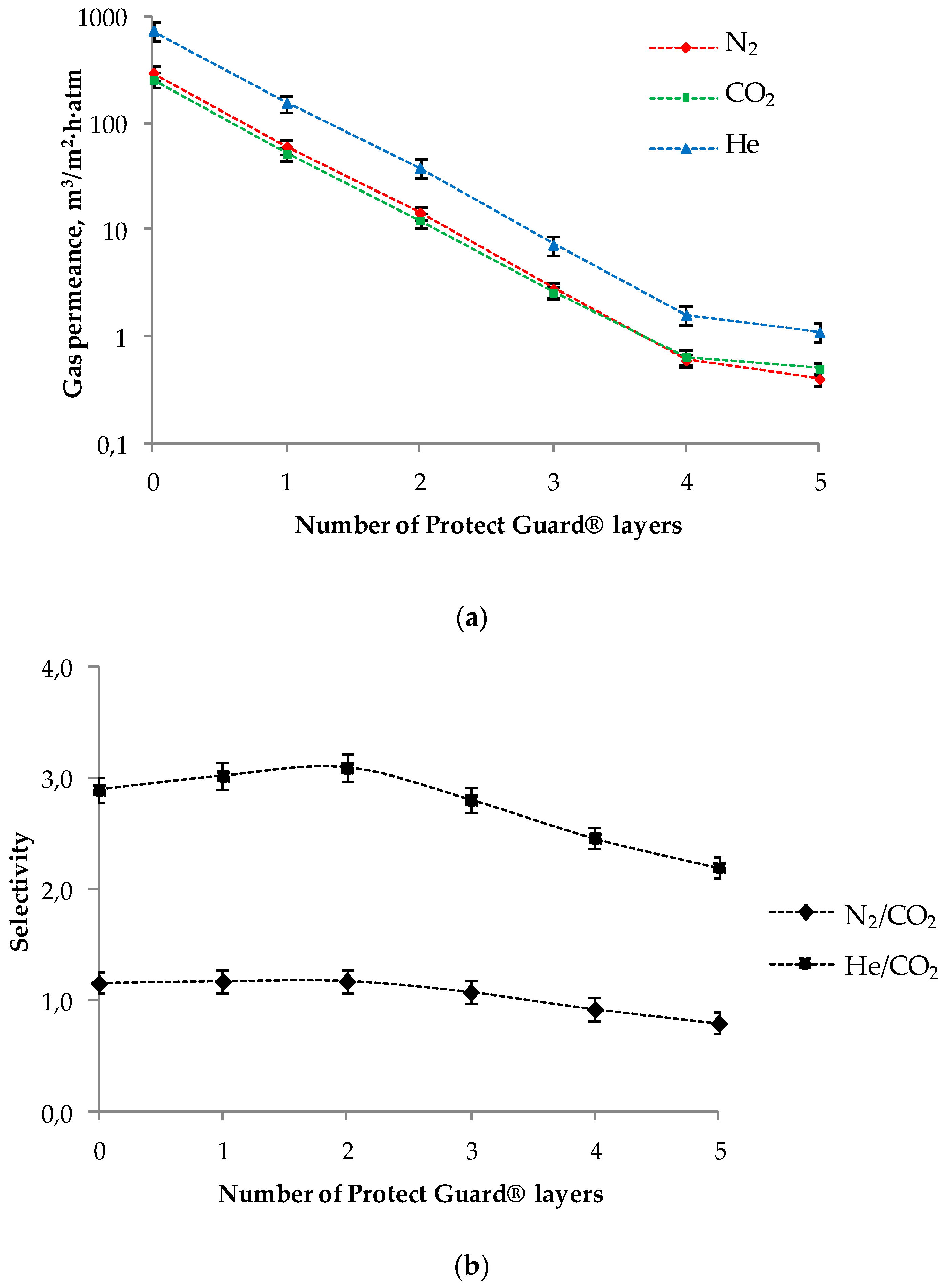
Gas permeance of the membranes was measured for nitrogen, carbon dioxide and helium using the constant pressure/variable volume method, on a laboratory setup described in [49]. The feed pressure was 0.5–2 bar, the permeate pressure was atmospheric. All experiments were carried out at room temperature (23 ± 2 °C). The molecular mass difference of these gases allows detecting the Knudsen flow regime based on ideal selectivity value (individual gases permeance coefficients ratio). Gas permeance of the membranes was calculated as follows:
P l = Q p S ,
where Q is the volumetric flow rate of the gas passed through the membrane, m3/h; p is the transmembrane pressure, atm; and S is the membrane area, m2.
As a result, the value of P/l (m3/(m2∙h∙atm)) was obtained.
Ideal selectivity value α was determined according to the equation:
α = P 1 P 2 ,
where Р1 and Р2 are the permeance values for the respective gases.

2.4.2. Surface Properties of the Hollow Fibers

Contact angle values were measured via the conventional sessile drop technique using the LK-1 goniometer (RPC OpenScience Ltd, Moscow, Russia). To determine the surface properties of unmodified and modified membranes and to find their surface energy values, water and ethylene glycol (Chimmed, Moscow, Russia) were used as test liquids. Furthermore, the membrane contact angle values were determined for chosen ionic liquids and silver salt solutions in ILs. All measurements were performed at room temperature (23 ± 2 °C). The contact angle value was determined as an arithmetical mean for three measurements. For image capture and digital processing of the drop images, the DropShape® software (Version 1.0, RPC OpenScience Ltd, Moscow, Russia) was used providing Laplace-Young contact angle calculation. Membrane surface energy value was determined according to the Owens-Wendt method [50]. This technique allows calculating the surface energy value γ as a sum of polar γp and γd dispersive components using two different liquids. The relation between surface energy and equilibrium contact angle of the liquid phase placed onto solid phase is derived from the Fowkes equation [51]:
γ 1 ( 1 + cos θ ) = 2 ( γ l d γ s d ) 1 / 2 + 2 ( γ l p γ s p ) 1 / 2 ,
where d and p subscripts relate to the dispersive and polar components of the liquid surface energy (γl) and the membrane surface (γs).
We used water and ethylene glycol as test liquids, as surface energy components of both these liquids are well known and widely described in the literature [52,53].

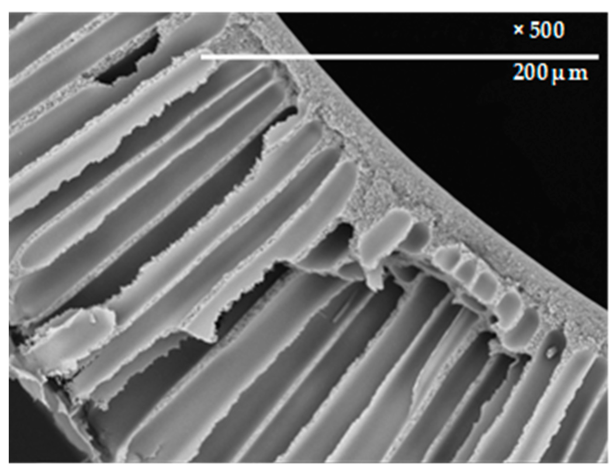
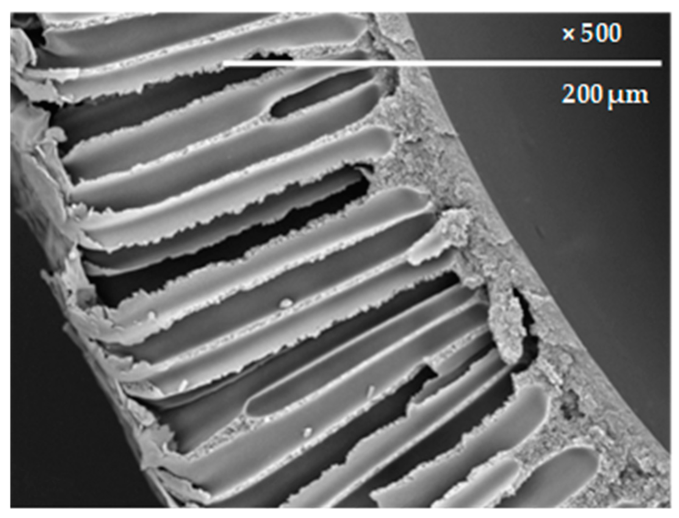
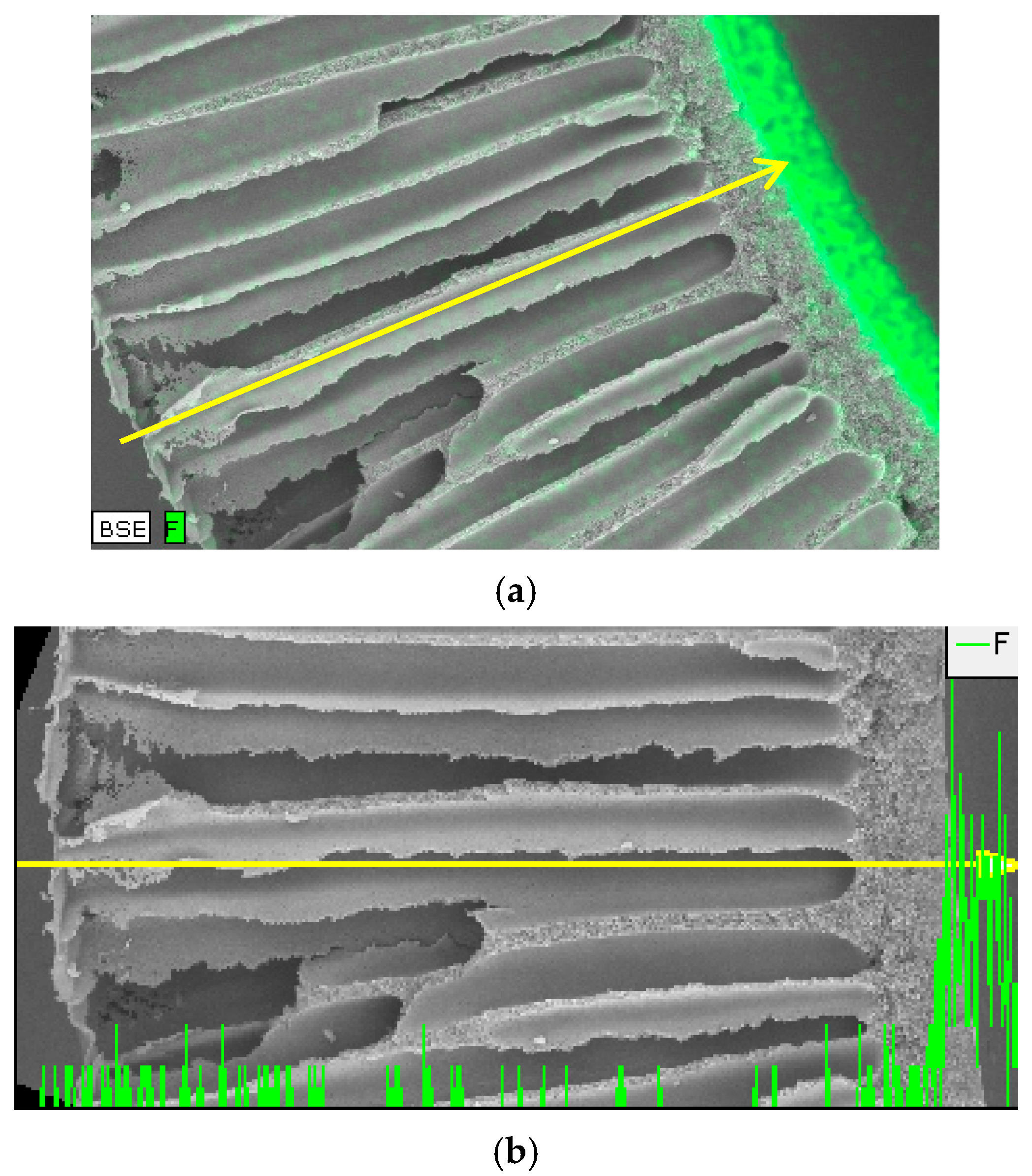
2.4.3. Scanning Electron Microscopy and EDXS Analysis

Cross sections and inner surface specimens of the hollow fiber membranes (both unmodified and modified) were studied via the scanning electron microscopy technique using Hitachi Table-top Microscope TM 3030 Plus with proprietary highly sensitive low-vacuum secondary electron detector (Hitachi High Technologies America Inc., Greenville, SC, USA), accelerating voltage was equal to 15 kV. For dispersive X-ray (EDXS) measurements, Bruker Quantax 70 EDXS system (Version ESPRIT 2, Bruker Ltd., Moscow, Russia) was used. Prior to image capture, the fibers were coated with gold (5 nm particles) by vacuum sputtering. The SEM images were processed with the Quantax 70 Microanalysis software (Version ESPRIT 2, Bruker Ltd., Moscow, Russia).

2.5. Dense PSf Membrane Preparation

The PSf pellets were exposed in a vacuum oven at 90 °C for 24 h in order to remove absorbed particles (e.g., water). After this procedure, the pellets were dissolved in chloroform under constant stirring by a magnetic stirrer for 4 h until the transparent solution with PSf content 1 wt. % was formed. The solution was filtered through filtering paper in nitrogen medium at 0.2 bar pressure. The transparent PSf films of ~70 µm width were fabricated by casting polymer solution onto the cellophane support with following slow evaporation of chloroform at room temperature for 7 days to constant weight.

2.6. Measurements of IL Sorption and Swelling in Dense PSf Membranes

The specimens of dense PSf membranes (films) with known size and weight were placed into pressurized vessels containing ILs studied and exposed under room temperature for 150 h. After the films were removed from the liquids, they were blotted with filtering paper in order to remove residual IL, and then the specimen weight and dimensions were determined. ILs sorption in PSf was calculated as
S = m m 0 m 0 ,
where m is the weight after exposure in IL, m0 is the initial weight of the specimen.
Polymer swelling degree (SD) was calculated as:
S D = d 1 · d 2 · l d 10 · d 20 · l 0 d 10 · d 20 · l 0 ,
where d10, d20 and l0 are the dimensions and width of the initial sample; d1, d2 and l are the dimensions and width of the sample after exposure in IL.

2.7. Preparation of Liquid Absorbents Based on ILs

Silver salts (AgBF4 and AgNO3) were dissolved in ionic liquids listed in Table 1 to concentration 0.2; 0.5; 0.9 and 1 M. All solutions were stirred for 24 h. The presence of opaque precipitates was checked visually. The resulting solutions were used to determine contact angle values for unmodified and modified membranes.

2.8. Ethylene/Ethane Separation in Membrane Contactor

The parameters of membrane contactor module are given in Table 2. The module was comprised by three hollow fibers placed into a stainless steel pipe with hot-melt end seals.
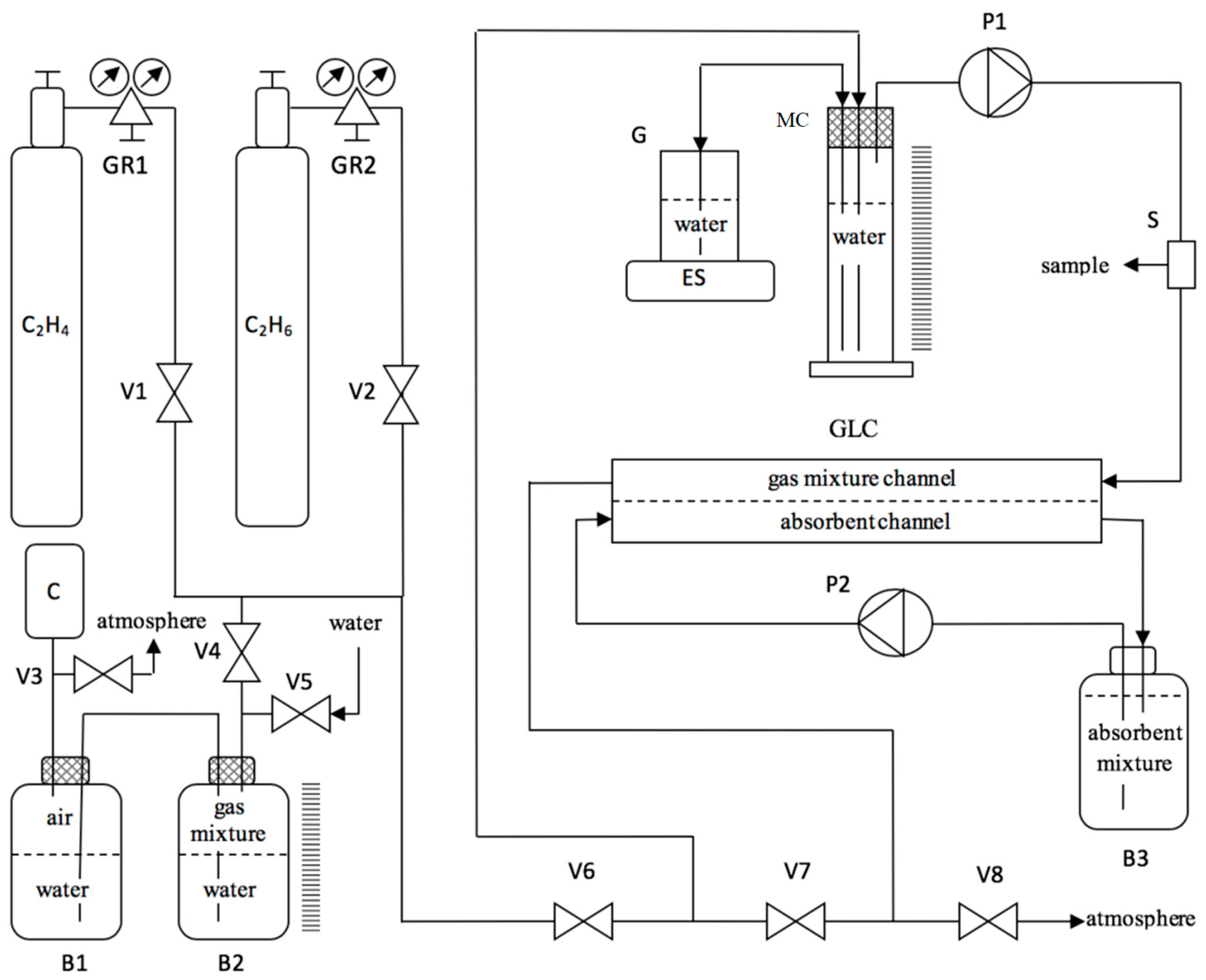
Gas-liquid membrane contactor experiments were carried out using the laboratory setup shown in Figure 1. Initial gas mixture volume was 270 mL, ethylene to ethane ratio in the mixture was 4:1, respectively. Liquid absorbent (500 mL) was put into the fibers lumen using peristaltic pump LS-301 (JSC “LOIP”, St. Petersburg, Russia). The experiments were performed at room temperature.
The experiments were carried out as follows: reservoir B3 was filled with water through valve V5 until water appeared in reservoir B2. After that, the outlet pressure of gas reducers GR1 and GR2 (model RPA1, Hy-Lok Corporation, Busan, Korea) was preset to 0.5 bar. A calculated amount of ethylene was brought into reservoir B2 using valves V1 and V4, and the respective volume of water passed from reservoir B2 to reservoir B1. Then, peristaltic pump P1 was turned off and valve V8 was closed, followed by the opening of valves V4 and V6, in order to put the preset volume of the gas mixture into measuring cylinder MC, using compressor C Schego Optimal (Schego, Leipzig, Germany). After that, the compressor C was turned off and valves V4 and V6 were closed. To blow down the gas channel of the contactor (GLC) with the gas mixture from measuring cylinder MC, valve V8 was opened and the peristaltic pump was turned on. After several (3–4) repeating cycles of blow down, valves V6 and V8 were closed, valve V7 was opened, and peristaltic pumps P1 and P2 were turned on. During the whole time of experiments, chromatographic samples were regularly collected from sampler S with simultaneous measuring of decreasing weight of water in glass G, according to the readings of electronic scales ES (model LN420 2CE, Vibra, Moscow, Russia)—in other words, the decrease of gas mixture volume in gas channel of the contactor GLC was measured.
Gas mixture composition during the experiments was analyzed using gas chromatograph Crystallux-4000M with a TCD detector (SDB “Meta-Chrom”, Yoshkar-Ola, Russia). The GC parameters were as follows: injection port temperature was 230 °C, the column temperature was 60 °C, and the detector temperature was 230 °C. The mixtures were analyzed on a Porapak N packed column (Agilent Technologies Inc., Santa Clara, CA, USA). The sample volume was 0.2 mL.

3. Results and Discussion

3.1. Characterization of Initial Membranes Using SEM

As can be seen from Figure 2, unmodified polysulfone hollow fibers have an asymmetrical structure consisting of thick drainage layer with finger-like channels, transitional layer with spongy structure and thin (2–3 µm) selective layer from the lumen side.

3.2. Gas Permeance of the Membranes

Figure 3a,b provides the results of gas permeance measurement for the unmodified PSf hollow fiber and the fibers modified by the hydrophobizing agent.
The unmodified membranes showed high gas permeance values. Ideal selectivity value α = 2.9 for He/CO2 indicates mixed gas flow regime between Poiseuille (α = 1) and Knudsen (α = 3.3) flows.
Gas permeance of the membranes modified by Protect Guard® is significantly lower than that of the initial sample even after the first deposition. With an increase in the number of modifying agent layers at the lumen surface of the fibers, their gas permeance declines monotonically (Figure 3a). At the same time, the selectivity does not change monotonically (Figure 3b): when the first and second layers are deposited, the selectivity tends to increase. For example, He/CO2 selectivity increases from 2.9 to 3.0–3.1, approaching to Knudsen flow regime (3.3). This fact indicates that deposition of first and second layers decreases the pore size. However, the selectivity under Knudsen flow regime begins to decrease when third, fourth and fifth layers of Protect Guard® are deposited. Probably, this can be accounted for by gradual closing of smaller pores by Protect Guard® layers.
A porous membrane for a gas-liquid membrane contactor should possess: (i) the minimum possible pore size in order to prevent penetration of absorbent in the membrane pores and (ii) maximum gas permeance to maintain high mass exchange properties of the contactor. Therefore, as follows from the gas permeance data (Figure 3a,b), deposition of two layers of Protect Guard® on the lumen surface of asymmetric PSf hollow fibers provides optimal trade-off between pore size and gas permeance of the membrane.

3.3. Surface Properties of the Membranes

The contact angle values for water and ethylene glycol of the unmodified and modified hollow fiber membranes are given in Table 3.
As can be seen from the data, even first deposition of Protect Guard® onto the lumen side of the fibers increases their contact angle values for both test liquids compared to the unmodified membranes, and the membrane becomes hydrophobic (water contact angle >90°). Due to the fluorine-containing group’s presence on the membrane surface, the contribution of polar surface energy component decreases significantly, whereas the dispersive component increases. Generally, the surface energy value of the membrane increases after modification. Further deposition of Protect Guard® layers does not lead to the decline of the surface energy.

3.4. IL Sorption and Swelling in Dense PSf Membranes

In the present works, ILs based on imidazolium cation were used, namely 1-ethyl-3-methyimizadolium dicyanamide ([Emim][DCA]), 1-ethyl-3-methylimidazolium tetrafluoroborate ([Emim][BF4]) and 1-butyl-3-methylimidazolium tetrafluoroborate ([Bmim][BF4]), and also those based on phosphonium cation: trihexyltetradecylphosphonium bis(2,4,4-trimethylpentyl)phosphinate ([P66614][Phos]) and trihexyl(tetradecyl)phosphonium bromide ([P66614][Br]). ILs based on imidazolium cation are easy to obtain and therefore are widely used in a number of applications, including absorption separation processes [18]. On the other hand, as shown in recent works [54,55], ILs based on phosphonium cation possess higher thermal and chemical resistance compared to imidazolium-based ones, which makes them promising for membrane contactor applications, considering the necessity of absorbent recovery at elevated temperatures.
The sorption and swelling degree values of PSf in the chosen ILs are given in Table 4.
As can be seen from Table 4, PSf shows very low sorption values in all the ILs studied: all sorption values are within the range of 0–0.02 g IL per g polymer. The polymer swelling degree in these ILs is also very low: 0–2%. Therefore, the data on sorption and swelling indicate that PSf is resistant towards the chosen ILs. The same observation was made in our work on another membrane material—PTMSP [56].

3.5. Contact Angle Values of Ionic Liquids for the Unmodified and Modified Membranes

Table 5 provides the data on contact angle values of ionic liquids for the unmodified and modified membranes.
It can be seen that membrane modification by Protect Guard® significantly decreases wetting by ILs. However, it should be noted that in the case of phosphonium-based ILs, even five layers of modifying agent do not provide sufficient decline of wettability, which is accounted for by low surface tension of these ILs. Therefore, we decided to choose imidazolium-based liquids for further study.

3.6. Silver Salt Solutions in the Ionic Liquids Based on Imidazolium Cation

Solutions with different silver salts (AgBF4 and AgNO3) concentration in three ionic liquids were prepared (Table 6). It can be seen that, in the case of [Emim][BF4], it is not possible to obtain a true solution of AgNO3. True solutions of AgBF4 exist at salt concentrations 0.9 M and lower. As mentioned in [35], the anion of [Emim][DCA] forms an insoluble precipitant with AgNO3. However, we did not observe precipitation for the 1 M solution of AgNO3 in [Emim][DCA].

3.7. Contact Angle Values of Silver Salts Solutions in Ionic Liquids for the Unmodified and Modified Membranes

Table 7 lists the contact angle values of silver salts solutions in ionic liquids for the unmodified and modified membranes.
A comparison between the data from Table 5 and Table 7 allows for the conclusion that the introduction of silver salts leads to the decreasing in the contact angle value. Generally, the introduction of salts shows the same tendency as for pure ILs: deposition of modifying agent significantly increases the contact angle. Also, AgNO3 solutions in [Emim][DCA] provide higher contact angle values than in case of AgBF4 solutions in [Emim][BF4]. Therefore, one can expect that the possibility of wetting and penetration of absorbent liquid for the modified membrane is less probable for AgNO3 solution in [Emim][DCA]. Furthermore, since ethylene/ethane separation is based on ethylene complexation with silver ions, systems with higher silver salt concentration seem to be more promising. Taking this into account, further research of membrane contactor was carried out using the 1 M solution of AgNO3 in [Emim][DCA].
Analysis of the results for gas permeance and contact angle measurements allows choosing an optimal technique for modification of membranes for contactor application. As can be seen from Table 3, Table 5 and Table 7, deposition of three and more layers of the modifying agent does not result in significant increase of membrane hydrophobicity and decrease in wetting by silver salt solutions in ILs. Deposition of two layers provides the necessary hydrophobicity while leaving the membrane structure porous and thus enabling the Knudsen regime of gas transport (see Figure 3a). Therefore, further research on ethylene/ethane separation in membrane contactor was carried out using porous asymmetric PSf membranes modified by deposition of two layers of Protect Guard® and 1 M solution of AgNO3 in [Emim][DCA] as liquid absorbent.

3.8. SEM and EDXS Analysis of the Modified Membranes

Figure 4 shows cross-sectional SEM of PSf hollow fiber membrane modified by 2 layers of hydrophobizing agent Protect Guard®.
As well as the unmodified membranes (Figure 2), the modified hollow fibers have an asymmetrical structure consisting of thick drainage layer with finger-like channels, transitional layer with spongy structure and thin (2–3 µm) selective layer from the lumen side. This indicates that the modifying agent does not affect the morphology of the membranes. Additional EDXS analysis (Figure 5) illustrates the fluorine distribution by the membrane width. Fluorine is an illustrative element since it is present only in the liquid modifier Protect Guard®, which is a perfluorinated acrylic copolymer. Figure 5 shows that Protect Guard® does not penetrate into the membrane pores, being therefore present only in the lumen side.

3.9. Ethylene/Ethane Separation in Membrane Contactor

Figure 6 shows the correlation between the concentration of gas mixture components and the duration of the experiment on ethylene/ethane separation in membrane contactor based on PSf hollow fibers modified by two layers of the hydrophobizing agent Protect Guard®. The 1 M solution of AgNO3 in [Emim][DCA] was used as a liquid absorbent.
When flowing in the shell side of the fibers, some amount of gas mixture penetrates through the membrane and becomes absorbed by aqueous AgNO3 solution. It should be pointed out that ethylene is absorbed preferentially due to the complexation reaction with silver ions. Therefore, the mole fraction of ethylene at the output of the contactor decreases, whereas ethane fraction increases.
The fluxes of both mixture components and the overall mass transfer coefficients were calculated for the studied system (Figure 7).
The flux of a gas mixture component (сm3 (STP)/сm2∙s) in the contactor was determined as
J = V 0 V t t S 273 T ,
where V0 (cm3) is the initial volume of a component in the mixture, Vt is the volume of a component to the moment of time t (s), S (cm2) is the interfacial area of hollow fibers in contactor, and T is the temperature (K). In our experiments, T was equal to 298 K.
The mass transfer coefficient (MTC) (cm/s) was calculated as:
K = J / 22,414 Δ χ ¯ R T p ,
where J/22,414 (mol/cm2·s) is the molar gas flux of a component from Equation (5), Δχ is the log-mean of the molar fraction difference of ethylene between feed and permeate phases, R is the gas constant and p is the total gas pressure in the feed phase (in our case p is ~0.1 MPa). To obtain the MTC value expressed in GPU (1 GPU = 10−6 cm3 (standard T and p)/(cm2·s·cm Hg), one should use the expression K (GPU) = K (cm/s)∙3.594∙106/T.
As can be seen from Figure 7, the values of J and MTC decrease with time, particularly, MTC decreases from 4.7 to 2.2 GPU. This is accounted for by the fact that the experiments were carried out in a closed system and the driving force was decreasing due to ethylene sorption.
It should be noted that, despite the decrease in MTC value with time, the values obtained in the present work are generally comparable with those described in the literature. The following MTC values were obtained in the works on ethylene/ethane separation in gas-liquid membrane contactors with aqueous silver salt solutions as absorbent: 18.3 GPU [13], 8.5 GPU [23], 2.8 GPU [57], and 11.5 GPU [58]. All the values mentioned are calculated based on experimental data obtained in corresponding works and represent the best data achieved under highest silver concentrations. As for silver salts solutions in ionic liquids, to the best of our knowledge, only Ortiz and Fallanza studied the performance of gas–liquid membrane contactors with these absorbents. In [57], propylene/propane separation is performed using not only aqueous AgBF4 solution, but also AgBF4 solution in ionic liquid BmimBF4, and in this case, the mass transfer coefficient value was ~2.3 GPU.

4. Conclusions

In the present work, porous hollow fiber PSf membranes were obtained and their surface was modified by perfluorinated acrylic copolymer Protect Guard®. The membranes were analyzed through gas permeance measurement, SEM and EDXS, and contact angle measurement. Analysis of the data obtained showed that deposition of two layers of the modifying agent onto the lumen surface of asymmetric hollow fiber PSf membranes provides necessary hydrophobicity and the optimal trade-off between gas permeance and porous structure, the latter providing Knudsen gas flow regime. Furthermore, the modification significantly increases the contact angle value for both pure ILs and silver salts solutions in ILs, thus decreasing the probability of membrane wetting and absorbent penetration. The experiments on sorption and swelling confirmed that polysulfone is resistant towards the ionic liquids studied. According to the SEM data, the structure of modified membranes remains the same as in the case of the unmodified membranes, which means that the modifying agent does not affect the membrane morphology. EDXS analysis showed that the modifying agent does not penetrate into the membrane thus being present only on the lumen surface.
The optimal absorbent composition was found—silver salt solution in the ionic liquid, namely, 1 M solution of AgNO3 in [Emim][DCA], since it was possible to dissolve the highest amount of silver salt in this IL, and furthermore, this solution provides the highest contact angle values.
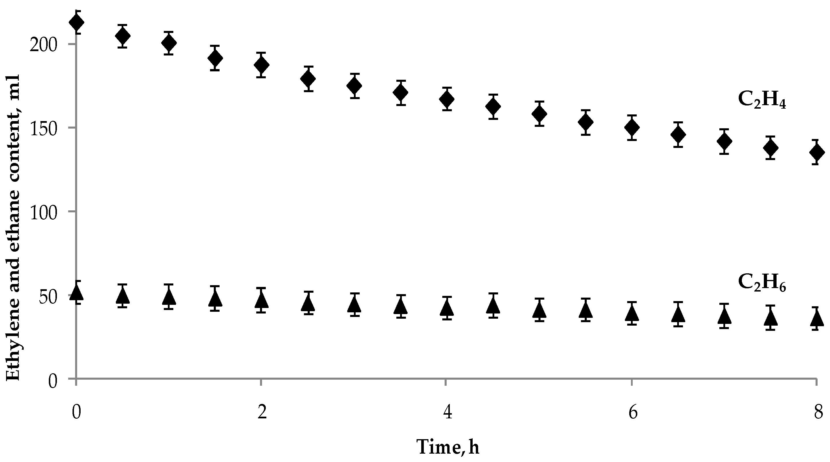
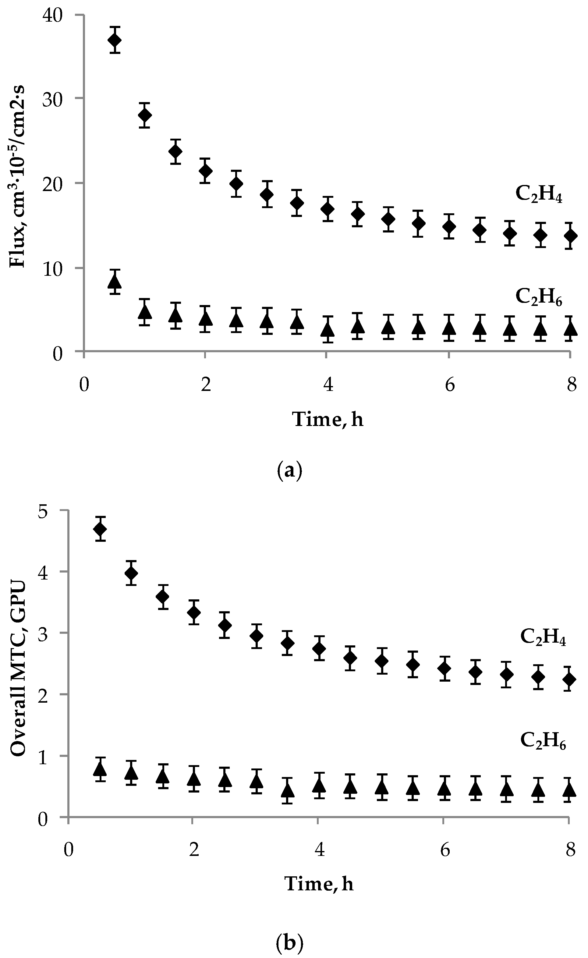
The membranes modified by deposition of two layers of the hydrophobizing agent were employed in ethylene/ethane separation in gas-liquid membrane contactor using 1 M solution of AgNO3 in [Emim][DCA] as liquid absorbent. It was shown that approximately 37% of the initial ethylene volume is absorbed during 8 h of the experiment, given the initial ethylene to ethane ratio 80:20. The mass transfer value differs from 2.2 to 4.7 GPU.

Author Contributions

Conceptualization, V.V. and S.B.; methodology, V.V. and S.B.; investigation, M.K.; data analysis, S.B., M.K., I.B., T.P. and V.V.; writing—original draft preparation, M.K.; writing—review and editing, T.P., S.B. and V.V.

Funding

This work was carried out in A.V. Topchiev Institute of Petrochemical Synthesis (Russian Academy of Sciences) and was funded by Russian Science Foundation, grant number 14-49-00101. Part of this work (study of dense PSf membranes and their compatibility with ionic liquids) was carried out within the State Program of TIPS RAS.

Acknowledgments

Authors thank K.A. Kutuzov and D.S. Bakhtin for experimental research assistance.

Conflicts of Interest

The authors declare no conflict of interest. The funders had no role in the design of the study; in the collection, analyses, or interpretation of data; in the writing of the manuscript, or in the decision to publish the results.

References

  1. Amin, S.; Amin, M. Thermoplastic elastomeric (TPE) materials and their use in outdoor electrical insulation. Rev. Adv. Mater. Sci. 2011, 29, 15–30. [Google Scholar]
  2. Fu, G.C.; Grubbs, R.H. The synthesis of nitrogen heterocycles via catalytic ring-closing metathesis of dienes. J. Am. Chem. Soc. 1992, 114, 7324–7325. [Google Scholar] [CrossRef]
  3. Fu, G.C.; Grubbs, R.H. Synthesis of cycloalkenes via alkylidene-mediated olefin metathesis and carbonyl olefination. J. Am. Chem. Soc. 1993, 115, 3800–3801. [Google Scholar] [CrossRef] [Green Version]
  4. Eldridge, R.B. Olefin/paraffin separation technology: A review. Ind. Eng. Chem. Res. 1993, 32, 2208–2212. [Google Scholar] [CrossRef]
  5. Baker, R.W.; Low, B.T. Gas separation membrane materials: A perspective. Macromolecules 2014, 47, 6999–7013. [Google Scholar] [CrossRef]
  6. Bessarabov, D.G.; Sanderson, R.D.; Jacobs, E.P.; Beckman, I.N. High-efficiency separation of an ethylene/ethane mixture by a large-scale liquid-membrane contactor containing flat-sheet nonporous polymeric gas-separation membranes and a selective flowing-liquid absorbent. Ind. Eng. Chem. Res. 1995, 34, 1769–1778. [Google Scholar] [CrossRef]
  7. Mortaheb, H.R.; Mafi, M.; Mokhtarani, B.; Sharifi, A.; Mirzaei, M.; Khodapanah, N.; Ghaemmaghami, F. Experimental kinetic analysis of ethylene absorption in ionic liquid [Bmim]NO3 with dissolved AgNO3 by a semi-continuous process. Chem. Eng. J. 2010, 158, 384–392. [Google Scholar] [CrossRef]
  8. Faiz, R.; Li, K. Polymeric membranes for light olefin/paraffin separation. Desalination 2012, 287, 82–97. [Google Scholar] [CrossRef]
  9. Staudt-Bickel, C.; Koros, W.J. Olefin/paraffin gas separations with 6FDA-based polyimide membranes. J. Membr. Sci. 2000, 170, 205–214. [Google Scholar] [CrossRef]
  10. Krol, J.J.; Boerrigter, M.; Koops, G.H. Polyimide hollow fiber gas separation membranes: Preparation and the suppression of plasticization in propane/propylene environments. J. Membr. Sci. 2001, 184, 275–286. [Google Scholar] [CrossRef]
  11. Bachman, J.E.; Smith, Z.P.; Li, T.; Xu, T.; Long, J.R. Enhanced ethylene separation and plasticization resistance in polymer membranes incorporating metal–organic framework nanocrystals. Nat. Mater. 2016, 15, 845–849. [Google Scholar] [CrossRef] [PubMed]
  12. Kovvali, A.S.; Chen, H.; Sirkar, K.K. Glycerol-based immobilized liquid membranes for olefin−paraffin separation. Ind. Eng. Chem. Res. 2002, 41, 347–356. [Google Scholar] [CrossRef]
  13. Tsou, D.T.; Blachman, M.W.; Davis, J.C. Silver-facilitated olefin/paraffin separation in a liquid membrane contactor system. Ind. Eng. Chem. Res. 1994, 33, 3209–3216. [Google Scholar] [CrossRef]
  14. Krull, F.F.; Fritzmann, C.; Melin, T. Liquid membranes for gas/vapor separations. J. Membr. Sci. 2008, 325, 509–519. [Google Scholar] [CrossRef]
  15. Li, N.N. Separating Hydrocarbons with Liquid Membranes. U.S. Patent 3410794, 12 November 1968. [Google Scholar]
  16. Tsou, D.T.; Blachman, M.W. Facilitated Liquid Membranes for Olefin/Paraffin Gas Separations and Related Process. U.S. Patent No. 5135547, 4 August 1992. [Google Scholar]
  17. Ghasem, N.; Al-Marzouqi, M.; Ismail, Z. Gas–liquid membrane contactor for ethylene/ethane separation by aqueous silver nitrate solution. Sep. Purif. Technol. 2014, 127, 140–148. [Google Scholar] [CrossRef]
  18. Pabby, A.K.; Sastre, A.M. State-of-the-art review on hollow fibre contactor technology and membrane-based extraction processes. J. Membr. Sci. 2013, 430, 263–303. [Google Scholar] [CrossRef]
  19. Demontigny, D.; Tontiwachwuthikul, P.; Chakma, A. Comparing the absorption performance of packed columns and membrane contactors. In. Eng. Chem. Res. 2005, 44, 5726–5732. [Google Scholar] [CrossRef]
  20. Roizard, D. Gas–Liquid Membrane Contactor. In Encyclopedia of Membranes; Drioli, E., Giorno, L., Eds.; Springer: Berlin/Heidelberg, Germany, 2016; ISBN 978-3-642-40872-4. [Google Scholar]
  21. Rajabzadeh, S.; Teramoto, M.; Al-Marzouqi, M.; Kamio, E.; Yoshikage, O.; Maruyama, T. Experimental and theoretical study on propylene absorption by using PVDF hollow fiber membrane contactors with various membrane structures. J. Membr. Sci. 2010, 346, 86–97. [Google Scholar] [CrossRef]
  22. Chilukuri, P.; Rademakers, K.; Nymeijer, K.; van der Ham, L.; van den Berg, H. Propylene/propane separation with a gas/liquid membrane contactor using a silver salt solution. Ind. Eng. Chem. Res. 2007, 46, 8701–8709. [Google Scholar] [CrossRef]
  23. Faiz, R.; Fallanza, M.; Ortiz, I.; Li, K. Separation of olefin/paraffin gas mixtures using ceramic hollow fiber membrane contactors. Ind. Eng. Chem. Res. 2013, 52, 7918–7929. [Google Scholar] [CrossRef]
  24. Safarik, D.J.; Eldridge, R.B. Olefin/paraffin separations by reactive absorption: A review. Ind. Eng. Chem. Res. 1998, 37, 2571–2581. [Google Scholar] [CrossRef]
  25. Herberhold, M. Metal π-Complexes: Complexes with Mono-Olefinic Ligands; Elsevier Publishing Company: Amsterdam, The Netherlands, 1972. [Google Scholar]
  26. Keller, G.E.; Marcinkowsky, A.E.; Verma, S.K.; Williamson, K.D. Olefin recovery and purification via silver complexation. In Separation and Purification Technology; Li, N.N., Calo, J.M., Eds.; Marcel Dekker, Inc.: New York, NY, USA, 1992; Volume 1, pp. 59–83. ISBN 0-8247-8721-8. [Google Scholar]
  27. Nymeijer, K.; Visser, T.; Brilman, W.; Wessling, M. Analysis of the complexation reaction between Ag+ and ethylene. Ind. Eng. Chem. Res. 2004, 43, 2627–2635. [Google Scholar] [CrossRef]
  28. Muhs, M.A.; Weiss, T.F. Determination of equilibrium constants of silver-olefin complexes using gas chromatography. J. Am. Chem. Soc. 1962, 84, 4697–4705. [Google Scholar] [CrossRef]
  29. Bennett, M.A. Olefin and Acetylene Complexes of Transition Metals. Chem. Rev. 1962, 62, 611–652. [Google Scholar] [CrossRef]
  30. Agel, F.; Pitsch, F.; Krull, F.F.; Schulz, P.; Wessling, M.; Melin, T.; Wassercheid, P. Ionic liquid silver salt complexes for propene/propane separation. Phys. Chem. Chem. Phys. 2011, 13, 725–731. [Google Scholar] [CrossRef] [PubMed]
  31. Sanchez, L.; Meindersma, G.; Haan, A. Potential of Silver-Based Room-Temperature Ionic Liquids for Ethylene/Ethane Separation. Ind. Eng. Chem. Res. 2009, 48, 10650–10656. [Google Scholar] [CrossRef]
  32. Seddon, K.R. Ionic Liquids-A Taste of the Future. Nat. Mater. 2003, 2, 363. [Google Scholar] [CrossRef]
  33. Earle, M.J.; Esperanca, J.; Gilea, M.A.; Lopes, J.N.C.; Rebelo, L.P.N.; Magee, J.W.; Seddon, K.R.; Widegren, J.A. The Distillation and Volatility of Ionic Liquids. Nature 2006, 439, 831. [Google Scholar] [CrossRef]
  34. Azhin, M.; Kaghazchi, T.; Rahmani, M. A review on olefin/paraffin separation using reversible chemical complexation technology. J. Ind. Eng. Chem. 2008, 14, 622–638. [Google Scholar] [CrossRef]
  35. Camper, D.; Scovazzo, P.; Koval, C.; Noble, R. Gas Solubilities in Room-Temperature Ionic Liquids. Ind. Eng. Chem. Res. 2004, 43, 3049–3054. [Google Scholar] [CrossRef]
  36. Zhao, H.; Xia, S.; Ma, P. Use of ionic liquids as ‘green’ solvents for extractions. Chem. Technol. Biotechnol. 2005, 80, 1089–1096. [Google Scholar] [CrossRef]
  37. Moura, L.; Darwich, W.; Santini, C.; Gomes, M. Imidazolium-based ionic liquids with cyano groups for the selective absorption of ethane and ethylene. Chem. Eng. J. 2015, 280, 755–762. [Google Scholar] [CrossRef]
  38. Ramdin, M.; de Loos, T.W.; Vlugt, T.J.H. State-of-the-Art of CO2 Capture with Ionic Liquids. Ind. Eng. Chem. Res. 2012, 51, 8149–8177. [Google Scholar] [CrossRef]
  39. Dindore, V.Y. Gas Purification Using Membrane Gas Absorption Processes. Ph.D. Thesis, University of Twente, Enschede, The Netherlands, 19 November 2003. [Google Scholar]
  40. Rajabzadeh, S.; Yoshimoto, S.; Teramoto, M.; Al-Marzouqi, M.; Ohmukai, Y.; Maruyama, T.; Matsuyama, H. Effect of membrane structure on gas absorption performance and long-term stability of membrane contactors. Sep. Purif. Technol. 2013, 108, 65–73. [Google Scholar] [CrossRef]
  41. Kirsch, V.A.; Roldugin, V.I.; Bildyukevich, A.V.; Volkov, V.V. Simulation of convective-diffusional processes in hollow fiber membrane contactors. Sep. Purif. Technol. 2016, 167, 63–69. [Google Scholar] [CrossRef]
  42. Faiz, R.; Fallanza, M.; Boributh, S.; Jiraratananon, R.; Ortiz, I.; Li, K. Long term stability of PTFE and PVDF membrane contactors in the application of propylene/propane separation using AgNO3 solution. Chem. Eng. Sci. 2013, 94, 108–119. [Google Scholar] [CrossRef]
  43. Kanezashi, M.; Matsutani, T.; Nagasawa, H.; Tsuru, T. Fluorine-induced microporous silica membranes: Dramatic improvement in hydrothermal stability and pore size controllability for highly permeable propylene/propane separation. J. Membr. Sci. 2018, 549, 111–119. [Google Scholar] [CrossRef]
  44. Nymeijer, K.; Visser, T.; Assen, R.; Wessling, M. Composite hollow fiber gas-liquid membrane contactors for olefin/paraffin separation. Sep. Purif. Technol. 2004, 37, 209–220. [Google Scholar] [CrossRef]
  45. Nymeijer, K.; Visser, T.; Assen, R.; Wessling, M. Olefin-selective membranes in gas-liquid membrane contactors for olefin/paraffin separation. Ind. Eng. Chem. Res. 2004, 43, 720–727. [Google Scholar] [CrossRef]
  46. Nymeijer, K.; Visser, T.; Assen, R.; Wessling, M. Super selective membranes in gas–liquid membrane contactors for olefin/paraffin separation. J. Membr. Sci. 2004, 232, 107–114. [Google Scholar] [CrossRef]
  47. Sanchez, L.M.G. Functionalized Ionic Liquids: Absorption Solvents for Carbon Dioxide and Olefin Separation; Gildeprint: Enschede, The Netherlands, 2008; ISBN 978-90-386-1468-7. [Google Scholar]
  48. Ionic Liquids Database—IL Thermo. Available online: http://ilthermo.boulder.nist.gov (accessed on 29 October 2018).
  49. Ovcharova, A.; Vasilevsky, V.; Borisov, I.; Bazhenov, S.; Volkov, A.; Bildyukevich, A.; Volkov, V. Polysulfone porous hollow fiber membranes for ethylene-ethane separation in gas-liquid membrane contactor. Sep. Purif. Technol. 2017, 183, 162–172. [Google Scholar] [CrossRef]
  50. Owens, D.K.; Wendt, R.C. Estimation of the surface free energy of polymers. J. Appl. Polym. Sci. 1969, 13, 1741–1747. [Google Scholar] [CrossRef]
  51. Fowkes, F.M. Calculation of work of adhesion by pair potential summation. J. Colloid Interface Sci. 1968, 28, 493–505. [Google Scholar] [CrossRef]
  52. Volkov, V.V.; Lebedeva, V.I.; Petrova, I.V.; Bobyl, A.V.; Konnikov, S.G.; Roldughin, V.I.; Van Erkel, J.; Tereshchenko, G.F. Adlayers of palladium particles and their aggregates on porous polypropylene hollow fiber membranes as hydrogenization contractors/reactors. Adv. Colloid Interface Sci. 2011, 164, 144–155. [Google Scholar] [CrossRef] [PubMed]
  53. Kwok, D.Y.; Neumann, A.W. Contact angle measurement and contact angle interpretation. Adv. Colloid Interface Sci. 1999, 81, 167–249. [Google Scholar] [CrossRef]
  54. Ramdin, M.; Olasagasti, T.Z.; Vlugt, T.J.; de Loos, T.W. High pressure solubility of CO2 in non-fluorinated phosphonium-based ionic liquids. J. Supercrit. Fluids 2013, 82, 41–49. [Google Scholar] [CrossRef]
  55. Ramdin, M.; Amplianitis, A.; Bazhenov, S.; Volkov, A.; Volkov, V.; Vlugt, T.J.; de Loos, T.W. Solubility of CO2 and CH4 in ionic liquids: Ideal CO2/CH4 selectivity. Ind. Eng. Chem. Res. 2014, 53, 15427–15435. [Google Scholar] [CrossRef]
  56. Bazhenov, S.; Malakhov, A.; Bakhtin, D.; Khotimskiy, V.; Bondarenko, G.; Volkov, V.; Ramdin, M.; Vlugt, T.J.H.; Volkov, A. CO2 stripping from ionic liquid at elevated pressures in gas-liquid membrane contactor. Int. J. Greenh. Gas Control 2018, 71, 293–302. [Google Scholar] [CrossRef]
  57. Ortiz, A.; Gorri, D.; Irabien, Á.; Ortiz, I. Separation of propylene/propane mixtures using Ag+–RTIL solutions. Evaluation and comparison of the performance of gas–liquid contactors. J. Membr. Sci. 2010, 360, 130–141. [Google Scholar] [CrossRef]
  58. Ghasem, N.; Al-Marzouqi, M.; Sheta, N. Effect of Pressure on the Separation of Ethylene from Ethylene/Ethane Gas Mixture Using Hollow Fiber Membrane. Am. J. Polym. Sci. 2017, 7, 30–37. [Google Scholar] [CrossRef]
Figure 1. Scheme of the experimental setup for ethylene/ethane separation. GR1, GR2—gas reducers; P1, P2—peristaltic pumps; G—glass; ES—electronic scale; MC—measuring cylinder; S—sampler; GLC—gas-liquid contactor; C—air compressor; V1–V8—valves; B1–B3—technological reservoirs.
Fibers 07 00004 g001
Figure 2. Cross-sectional SEM images of polysulfone (PSf) hollow fiber membrane, magnification 500×.
Fibers 07 00004 g002
Figure 3. (a) Correlation between the number of the hydrophobizing agent layers and the gas permeance value and (b) correlation between the number of the hydrophobizing agent layers and the selectivity value.
Fibers 07 00004 g003
Figure 4. Cross-sectional SEM image of PSf hollow fiber membrane modified by two layers of the hydrophobizing agent Protect Guard®, magnification 500×.
Fibers 07 00004 g004
Figure 5. Dispersive X-ray (EDXS) analysis results for PSf membranes modified by Protect Guard®: (a) fragment of the selective layer, magnification 500× (fluorine is shown by green); (b) fluorine distribution by the membrane width.
Fibers 07 00004 g005
Figure 6. Change of gas components concentration with time.
Fibers 07 00004 g006
Figure 7. (a) Change in the gas flux; (b) the overall mass transfer coefficient values during the time of experiment.
Fibers 07 00004 g007
Table 1. Chemical structures and physico-chemical properties of the chosen ionic liquids (ILs).
NameChemical StructureViscosity, mPa∙sMol. Weight, g/moleDensity, g/cm3Henry’s Constant of Ethylene at 40 °C, kPa
[Emim] [DCA] Fibers 07 00004 i00114.5177.21.10834100
[Emim] [BF4] Fibers 07 00004 i00236.9198.01.283N/A
[Bmim] [BF4] Fibers 07 00004 i00399226.01.20121700
[P66614] [Phos] Fibers 07 00004 i0041402.0773.30.8852620
[P66614] [Br] Fibers 07 00004 i0052988.0563.80.959N/A
Table 2. Data on hollow fiber membrane contactor.
ParameterValue
Shell inner diameter, D (cm)0.3
Fiber outer diameter, do (cm)0.13
Fiber inner diameter, di (cm)0.08
Number of fibers, N3
Fiber length, L (cm)25
Specific surface area, a (cm2/cm3)11
Gas linear velocity, UG (m/s)0.23
Liquid linear velocity, UL (m/s)0.23
Table 3. Contact angle and surface energy values for the unmodified and modified membranes.
Specimenθ Water, °θ Ethylene Glycol, °γsp, mJ/m2γsd, mJ/m2γs, mJ/m2
Unmodified78 ± 270 ± 219.76.926.6
1 deposition106 ± 285 ± 21.614.416
2 depositions102 ± 294 ± 26.64.711.3
3 depositions105 ± 284 ± 21.714.316
4 depositions113 ± 293 ± 20.711.812.5
5 depositions103 ± 285 ± 22.912.115
Table 4. Sorption and swelling degree of PSf in ILs.
LiquidSorption, g/gSwelling Degree, %
[Emim][DCA]0.010
[Emim][BF4]0.012
[Bmim][BF4]00
[P66614][Phos]0.022
[P66614][Br]0.021
Table 5. Contact angle values of ionic liquids for the unmodified and modified membranes.
Membraneθ [Emim][BF4], °θ [Emim][DCA], °θ [Bmim][BF4], °θ [P66614][Phos], °θ [P66614][Br], °
Unmodified72 ± 249 ± 225 ± 215 ± 27 ± 2
1 deposition86 ± 285 ± 281 ± 256 ± 259 ± 2
2 depositions84 ± 2100 ± 289 ± 264 ± 267 ± 2
3 depositions96 ± 2100 ± 284 ± 257 ± 262 ± 2
4 depositions86 ± 297 ± 295 ± 247 ± 259 ± 2
5 depositions90 ± 295 ± 280 ± 249 ± 252 ± 2
Table 6. Silver salts solutions in ionic liquids.
Concentration, MAgBF4AgNO3
[Emim][BF4][Emim][DCA][Bmim][BF4][Emim][BF4][Emim][DCA][Bmim][BF4]
1opaqueopaqueopaqueopaquetransparentopaque
0.9opaqueopaquetransparentopaquetransparentopaque
0.5opaquetransparenttransparentopaquetransparentopaque
0.2opaquetransparenttransparentopaquetransparentopaque
Table 7. Contact angle values of silver salts solutions in ionic liquids for the unmodified and modified membranes.
SaltILMembrane
Unmodified1 Layer2 Layers3 Layers4 Layers5 Layers
AgNO3, 1 M[Emim][DCA]49 ± 291 ± 290 ± 291 ± 286 ± 296 ± 2
AgNO3, 0.5 M[Emim][DCA]44 ± 278 ± 288 ± 295 ± 295 ± 293 ± 2
AgBF4, 0.9 M[Bmim][BF4]37 ± 283 ± 273 ± 274 ± 267 ± 269 ± 2
AgBF4, 0.5 M[Bmim][BF4]44 ± 268 ± 258 ± 266 ± 278 ± 276 ± 2
AgBF4, 0.5 M[Emim][DCA]47 ± 282 ± 288 ± 282 ± 294 ± 283 ± 2

