Temperature Dependent Strain/Damage Monitoring of Glass/Epoxy Composites with Graphene as a Piezoresistive Interphase


1
Department of Industrial Engineering, University of Trento, via Sommarive 9–38123 Trento, Italy
2
National Interuniversity Consortium of Materials Science and Technology (INSTM), via Giuseppe Giusti 9–50121 Florence, Italy
*
Authors to whom correspondence should be addressed.
Fibers 2019, 7(2), 17; https://0-doi-org.brum.beds.ac.uk/10.3390/fib7020017
Submission received: 19 November 2018
/
Revised: 11 February 2019
/
Accepted: 15 February 2019
/
Published: 21 February 2019
(This article belongs to the Special Issue Glass Fibers 2018)
Abstract
:Graphene as an interphase not only improves the mechanical performance of fiber reinforced polymer composites but also induces functional properties like electrical conductivity, thus providing the possibility of strain monitoring in real time. At this aim, graphene oxide (GO) was electrophoretically deposited at different applied potentials on glass fibers to create a uniform coating and was subsequently chemically reduced to obtain a conductive layer of reduced graphene oxide (rGO). After the optimization of the deposition process, composite laminates were prepared by hand lay-up with an epoxy resin, followed by curing in vacuum bag. The deposited rGO interphase improved the dynamic moduli (storage and loss modulus), the flexural strength (+23%), and interlaminar shear strength (ILSS) (+29%) of the composites. Moreover, laminates reinforced with rGO-coated glass fibers showed an electrical resistivity in the order of ~101 Ω·m, with a negative temperature coefficient. The piezoresistivity of the composites was monitored under flexural loading under isothermal conditions, and strain/damage monitoring was evaluated at different temperatures through the change of the electrical resistance with the applied strain.
1. Introduction
Structural fiber reinforced polymer composites have received wide attention from both academic and industrial communities for their advantages in several applications because of their high strength-to-weight ratio, better corrosion resistance with respect to metallic materials, excellent impact strength, and durability [1]. However, the utmost requirement that is first evaluated for the applicability of such materials is the mechanical performance, which in turn has a great dependence on the fiber/matrix interfacial adhesion. In other words, the effective load transfer from the matrix to the fibers is the primary factor on which the mechanical performance is determined [2]. Researchers are constantly looking for better design, material selection, and production systems in order to assure optimal load transfer [3]. In recent years, this issue has been successfully faced by the use of nanostructured materials dispersed in the matrix or deposited on the fiber surface, which are able to create a better interphase for the load transfer mechanism [3].
Recent years have seen an enormous rise in the use of nanomaterials in polymer composites, due to their remarkable effect on the physical properties of the resulting materials [4,5,6,7,8,9]. The inclusion of carbonaceous nanomaterials (carbon nanotubes (CNTs), graphene), for example, has successfully modified the properties of both thermoplastic and thermosetting matrices [10,11,12], including the enhancement of the electrical conductivity [13,14,15]. In particular, the use of graphene in polymer composites could lead to the development of multifunctional materials that could be applied for innovative applications [16,17,18]. In the case of fiber reinforced polymer composites, several studies have been conducted to prove the positive impact of nanoparticles in enhancing the mechanical properties, either by dispersing them in the polymer matrix or depositing nanofillers on the fiber surface as a fiber/matrix interphase [3,19,20]. In the past, graphene oxide (GO) has been reported to be extremely effective in not only improving the fiber/matrix load transfer mechanism [21,22], but also in promoting the use of composite structures in strain monitoring sensors [23,24].
The topic of strain monitoring of structural materials has taken a great deal of attention in the past decade, mainly because of the possibility to obtain information about the damage evolution within the materials in real time conditions. Fiber reinforced polymer (FRP) structures, being particularly sensitive to intrinsic damage mechanisms (i.e., delamination or matrix cracking), are thus ideal candidates for real time damage monitoring and detection [25]. It is thus clear that the in-situ monitoring of damage is a useful tool to increase the reliability and lifetime of composite structures, also making the maintenance of structural components less challenging [26]. In the past, graphene has been used extensively in polymer composites. Strain monitoring sensitivities up to 16,400 were obtained by using functionalized graphene nanoplatelets as coating on glass fiber fabric [27]. Moreover, in epoxy matrix, a gauge factor of around 750 was achieved by the addition of graphene nanoplatelets (GNPs) [24]. Similarly, it was proven that functionalized graphene in polyvinylidene fluoride (PVDF) performed better as a strain sensor compared to carbon nanotube polymer composite [28].
Recently, fiber reinforced polymer composites have been developed using various “built-in sensors” that have the capability to monitor their structural health [26]. In particular, carbon fibers have been used as a multifunctional element, primarily for their structural capabilities as well as for their elevated electrical conductivity, which qualifies the composite itself for damage monitoring by the phenomenon of piezoresistivity, i.e. the change of electrical resistance of an element due to an application of a certain stress (or strain) [29]. In this sense, the use of glass fibers (GF) reinforced laminates for these applications is strongly limited, because of the intrinsic insulating properties of both the fibers and the polymer matrix. To achieve elevated electrical conductivity in glass fiber-based composites, several techniques have been utilized in the past [30,31,32,33]. Böger et. al [34] dispersed carbonaceous nanofillers in an epoxy matrix to perform load and strain monitoring of glass/epoxy composites. In the same way, Gao et. al [35] utilized multi-walled carbon nanotubes in an epoxy matrix reinforced with glass fibers, in order to evaluate the mechanisms of damage sensing under cyclic loading conditions. The difficulty in the dispersion of nanofillers in epoxy matrix arises from the fact that an increase of the nanofiller loading causes an increase in the viscosity [36,37], thus leading to processability problems that could potentially impair the mechanical performances of the resulting materials [38].
In order to overcome these problems, researchers tried to implement a selective deposition of nanofillers on the fiber surface through various techniques, such as dip coating [27], chemical vapor deposition (CVD) [39], chemical grafting [40], and electrophoretic deposition (EPD) [41]. EPD has recently proved to be a practical technique when depositing large amounts of nanosized particles on various substrates [42,43,44]. In a recent work, Mahmood et al. [25] investigated the strain monitoring capability of glass/epoxy composites, in which a graphene interphase was created between the matrix and the reinforcement through EPD, starting from a GO water suspension with a concentration of 1 mg/mL (equivalent to 0.1 wt%), deposited applying an electrical field of 10 V/cm. GO was then chemically reduced to reduced graphene oxide (rGO) by lowering the oxygen content as low as 10% in the rGO sheets. Such continuous deposition on GF provided an improvement of about 70% of the fiber/matrix interfacial shear strength. Interestingly, the produced rGO based epoxy/glass composites were characterized by a volume resistivity as low as 4.5 Ω·m. However, in that work, the process parameters of the EPD were not optimized, and their influence on the physical properties of the coating and of the resulting composites was not determined.
On the basis of these considerations, the current work is focused on the investigation of the optimal parameters of the EPD technology (applied electric field and concentration of GO dispersion required to create a uniform and continuous deposition of rGO on GF), to develop electrically conductive glass/epoxy composites. Moreover, considering that no papers can be found in the literature on the temperature-dependent health monitoring capability of nanomodified hybrid epoxy composites, the piezoresistive response of the resulting laminates at three different temperatures (i.e., 0 °C, 23 °C, and 50 °C) was investigated.
2. Materials and Methods
2.1. Materials
A dispersion of 4 mg/mL of graphene oxide in water was purchased from Graphenea SA (San Sebastian, Spain). According to the producer’s datasheet, this dispersion has a GO monolayer content of more than 95%. A unidirectional fabric of glass fibers (UT-E500), having a surface density of 500 g/m2, was provided by Gurit (Wattwil, Switzerland). A bicomponent epoxy resin, constituted by an epoxy base (EC157) and an aminic hardener (W342), was provided by Elantas Europe Srl (Parma, Italy). As reported in the producer’s datasheet, this system presents a glass transition temperature (Tg) of around 88 °C after a curing cycle of 24 h at room temperature, followed by 15 h at 60 °C. All the materials were used as received.
2.2. Samples Preparation
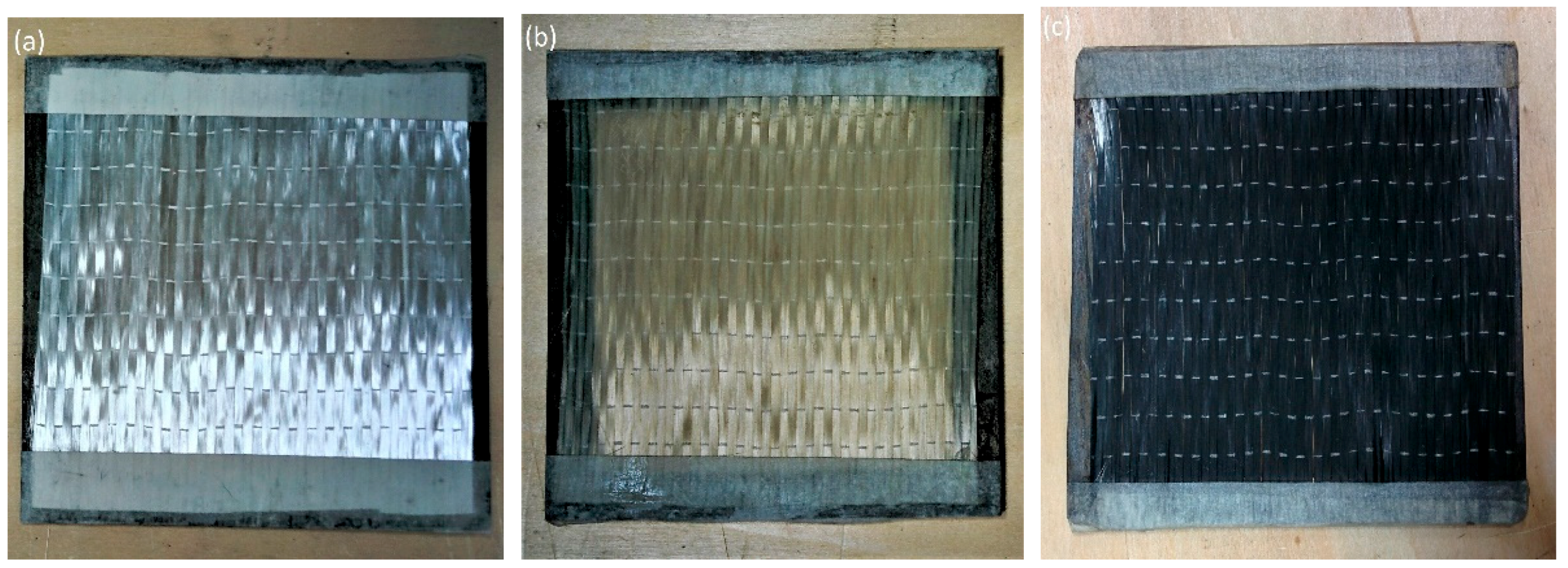
In the electrophoretic deposition (EPD) process, two electrodes were inserted in a conductive suspension and connected together using a direct current power supply. GF were mounted on a steel frame (as shown in Figure 1a) and were placed in front of the anode during EPD, due to the fact that GO is negatively charged.
Through the application of an electrical potential between the electrodes, GO is forced to migrate towards the anode, thus depositing on the GF. In order to optimize the EPD parameters, various concentrations of GO solution (ranging from 0.005 wt% to 0.02 wt%) and different electric field intensities (from 0.5 to 1.5 V/cm) were applied. In this work, the electric field intensity was defined as the ratio between the voltage applied and the distance between the electrodes. During the EPD process, the distance between the electrodes was kept constant at 2 cm, and both sides of the glass fiber fabric were treated for 5 min. The configuration of the experimental equipment used in the EPD treatment was taken from the previous work of Mahmood et al. [25], in order to directly compare the results, while the deposition conditions (i.e., GO concentration and applied electric field) were systematically modified. The complete list of the conditions of the electrophoretic deposition of GO on glass fibers is reported in Table 1.
After the deposition, the GO-coated fibers were dried in an oven under vacuum at 50 °C for at least 12 h. The surface appearance of both uncoated and coated fabrics can be observed in Figure 1a,b, respectively. The treated fibers were then subjected to chemical reduction in an environment of hydrazine hydrate at 100 °C for 24 h to reduce GO to rGO. The details of the chemical reduction process can be found in the previous work of Mahmood et al. [25]. Regardless of the adopted parameters, the color of the fibers passed from light brown to black (Figure 1c) after the chemical reduction.
Both uncoated and rGO-coated fibers were used to fabricate unidirectional composites, with the epoxy resin as matrix. A hand lay-up method was adopted, stacking 4 laminae of the glass fabric. The system was then placed in a vacuum bag to remove the air bubbles and the excess resin. The curing process was performed according to the indications of the producer (i.e., 24 h at ambient temperature followed by 15 h at 60 °C). In this way, laminates having a dimension of 150 mm × 150 mm × 1.3 mm were prepared. On the other hand, for the short beam shear test (SBS), 12 laminas were stacked to create a thicker composite specimens (thickness of about 3.7 mm). The neat epoxy resin was designed as EP and the uncoated GF reinforced composite was denoted as EP-GF, while the laminate reinforced with rGO-coated fibers were coded as EP-rGO-GF. It is important to underline that, in the preparation of the composites, only the fibers coated with an optimized EPD condition (i.e., 2A of Table 1) were used.
2.3. Experimental Techniques
2.3.1. Characterization of the Fibers
The morphological analysis of both the uncoated and coated fibers was performed by scanning electron microscopy (SEM) using a Zeiss Supra 40 microscope (Zeiss, Oberkochen, Germany). Before observations, specimens were coated by a platinum/palladium alloy (80:20) thin layer with a thickness of about 5 nm.
Based on the electrical resistivity values of the investigated materials, two different resistivity measurement methods were utilized. For uncoated GF, whose resistivity level exceeds 105 Ω·m, the electrical resistivity was measured using a Keithley 8009 resistivity test chamber (Keithley Instruments, Cleveland, OH, USA) coupled with a Keithley 6517A high-resistance meter (Keithley Instruments, Cleveland, OH, USA) at 5 V applied voltage. On the other hand, the electrical resistivity at 23 °C of rGO-coated fibers at different EPD conditions was measured by using a Keithley 6517A electrometer in 4-point configuration (Keithley Instruments, Cleveland, OH, USA). Three different fiber strands (width 0.7 cm, length 4 cm) were tested for each sample, applying voltage levels from 0.1 V to 5 V (depending on the electrical resistivity of the fibers).
2.3.2. Characterization of the Composites
The density of the neat epoxy matrix and of the composites was measured at 23 °C by using a precision balance (Archimede Gibertini E42, Gibertini, Modena, Italy) which had a sensitivity of 10−4 g. The specimens were weighed in air and in ethanol, according to the ASTM standard D792-13. The density of the GF was measured by using a Micromeritics® Accupyc 1330 helium pycnometer (Micromeritics Instrument Corporation, Norcross, GA, USA) at ambient temperature 23 °C, using a testing chamber of 3.5 cm3.
The fiber volume fraction (Vf) in the composites was evaluated by using the expression reported in the following Equation (1):
where ρf and ρm are the densities of the fiber and matrix, while Wf is the fiber weight fraction.
The theoretical density (ρt) of the composite specimens was then estimated using Equation (2):
where Vm represents the matrix volume fraction.
It is possible to also estimate the volume fraction of the voids (θvoids) in the specimen using Equation (3):
Optical microscope images of the cross section of the composite laminates were obtained through a Zeiss Axiophot optical microscope (EL-Einsatz 451887, Zeiss, Oberkochen, Germany), equipped with a Leica DC300 digital camera (Leica Microsystems Ltd., Heerbrugg, Switzerland). The specimens were polished using abrasive grinding papers with grit size P800, P1200, and P4000, sequentially.
The thermal stability of epoxy and glass/epoxy composites was assessed through thermogravimetric analysis (TGA) by using a Q5000IR thermobalance by TA Instruments (New Castle, DE, USA). Around 10 mg and 40 mg of the neat epoxy and of the composites were tested respectively, under a nitrogen flow of 100 mL/min. The tests were conducted between 25 °C and 700 °C, at a heating rate of 10 °C/min. The onset degradation temperature (Tonset) was computed by the intersection of the extrapolated TGA curve and the tangent line of the curve. Temperature corresponding to a weight loss of 5% (T5%) was also determined. The degradation temperature (Td) was taken as the temperature associated with the maximum mass loss rate, and the residual mass at 700 °C (rm) was also detected.
The viscoelastic behaviour of the composites was evaluated through dynamical mechanical analysis (DMA), by using a DMAQ800 machine, provided by TA instruments (New Castle, DE, USA), operating in dual–cantilever mode. Analysis was carried out in a temperature range between 0 and 150 °C at a heating rate of 3 °C/min and a frequency of 1 Hz.
Flexural mechanical properties of the composite laminates were determined by using an Instron® 5696 universal testing machine (Instron, Norwood, MA, USA), according to ASTM D790 standard. Rectangular specimens with dimension of 150 mm × 13 mm × 1.3 mm were tested, imposing a span to depth ratio of 60:1 and 40:1 for the measurement of flexural modulus and flexural strength, respectively. In order to apply a strain rate of 0.01 mm−1, cross-head speeds of 7.8 mm/min for flexural modulus evaluation and 3.5 mm/min for flexural strength tests were selected. At least five specimens were tested for each composition. Interlaminar shear strength (ILSS) values of the composites were determined through a Short Beam Shear test (SBS), performed according to the ASTM D2344 standard, by using an Instron® 5969 tensile testing machine. Specimens with dimensions of 22.2 mm × 7.4 mm × 3.7 mm were tested under 3-point bending configuration at a speed of 1 mm/min. The ILSS was determined from the maximum load sustained by the samples (Fmax), by using the expression reported in the following Equation (4):
where b and h are the width and the height of the specimens, respectively.
The electrical volume resistivity of the EP-rGO-GF composites was tested through a 6-1/2-digit electrometer (Keithley model 6517A) in a 2-point configuration at three different temperatures (0 °C, 23 °C, and 50 °C) under an applied voltage of 10 V. At least five specimens were tested for each composition. The piezoresistivity of the EP-rGO-GF composite was measured under flexural loading at three different temperatures (i.e., 0 °C, 23 °C, and 50 °C) by using an Instron® 5969 tensile testing machine. Rectangular samples with dimensions of 150 mm × 13 mm × 1.3 mm were mechanically tested at 3.5 mm/min, simultaneously measuring the electrical resistance through a Keithley 6517A electrometer under 2 contact points, setting a distance between the electrodes of 30 mm [25]. The temperature was controlled during the tests by conducting the experiments in a thermostatic chamber. The piezoresitivity of the EP-rGO-GF laminate was thus assessed through the variation of the relative electrical resistance (ΔR/R0, where R0 is the initial resistance at the beginning of the test) as a function of the applied flexural strain.
3. Results and Discussion
3.1. Characterization of the Fibers
The electrical resistivity of the rGO-coated fabric was measured under a 4-point configuration, and the most important results are summarized in Table 2. It can be observed that by applying a higher electric field and/or by using a higher GO concentration, it is possible to reach a decrease of resistivity. With a GO concentration of 0.005 wt% (0A–0C fibers), it is possible to obtain a resistivity in the order of ~103 Ω·m, while by increasing the GO amount up to 0.01 wt%, it is possible to produce fibers with a resistivity of ~102 Ω·m, especially when increasing the applied voltage. A further enhancement of the GO concentration (i.e., 0.02 wt%) results in a further decrease of the resistivity up to ~101 Ω·m. In this condition, it is important to underline that an increase of the voltage does not promote a resistivity decrease. This is the reason why 2A fibers probably represent the best compromise between the requirements of elevated conductivity and mild deposition conditions. It could be interesting to note that in our previous papers the EPD process was performed by using a GO water suspension with a concentration of 1 mg/ml (i.e., 0.1 wt%), applying an electrical field of 10 V/cm [25]. The fibers treated according to 2A process parameters were then utilized to prepare composite laminates.
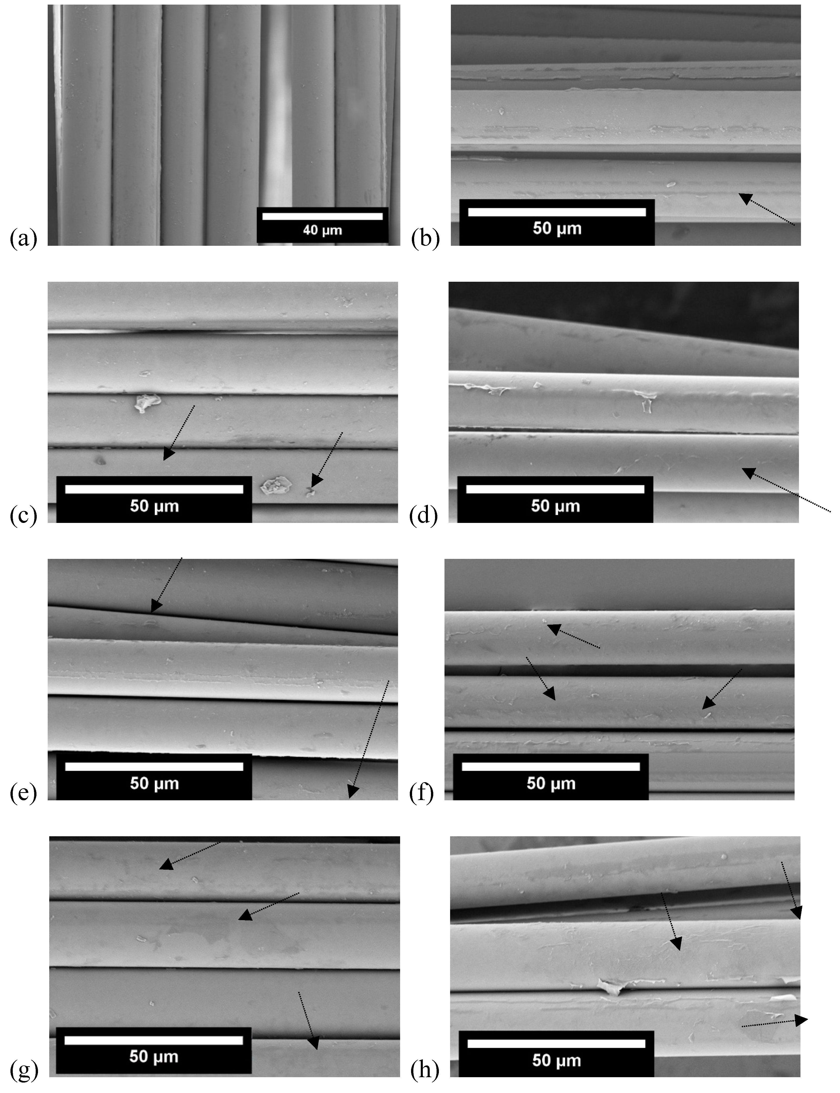
Figure 2a shows the micrographs of the neat glass fibers, while Figure 2b–j reports the micrographs of the glass fibers coated with rGO under different experimental conditions (the complete list of the process parameters is reported in Table 1). In comparison to the neat fiber (Figure 2a), GF coated by 0A, 0B, and 0C parameters (Figure 2b–d) hardly showed any physical deposition of rGO, meaning that the conditions used to create rGO coating were not satisfactory. This was further confirmed in the resistivity test of coated GFs discussed above (see Table 2). Similarly, the case of GF coated with rGO by 1A, 1B, and 1C revealed slightly more deposition, with either grey colored flakes adhered to the fiber surface and/or some wrinkle features of graphene (ubiquitous phenomenon in two-dimensional membranes) visible in Figure 2e–g. Further increasing the concentration of the GO dispersion, i.e., 2A, 2B, and 2C, resulted in increased deposition, which then showed a signficant deposition of the rGO flakes pointed out by arrows in Figure 2h–j. Even if a fine deposition of rGO was observed by these micrographs, it was not possible to determine the thickness of the deposited layer. For such reasons, cross-sectional pictures of neat GF and rGO-coated GF (under deposition condition 2A only) were attempted by SEM and reported in Figure 3.
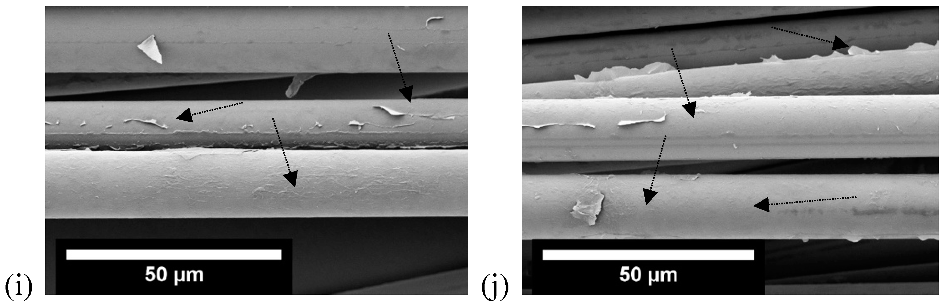
In order to visualize the coating thickness on the GF, the neat GF and rGO-coated GF (only deposited under 2A conditions) were analyzed for their cross-section under SEM. Figure 3a,b show the neat GF under low and high magnification, and only a few particles (presumably of the sizing of GF) can be viewed. On the contrary, Figure 3c,d show the flakes of rGO on the GF, either adhered to the GF or partially hanging from the GF, which also can be seen in Figure 2h–j. These images reveal a very fine coating of rGO on the GF, deposited under 2A condition. The average thickness of the coating was measured by taking 5 measurements from one image of fiber and then taking similar measurements from other fiber images (in this case, 5 images were used in total) using ImageJ software. The average thickness of rGO coating was found to be about 45 ± 9 nm.
3.2. Characterization of the Composites
In order to compare the properties of the produced laminates, it is important to evaluate their fiber content, density, and porosity. The fibers used to create the composite structure were weighed before composite fabrication with epoxy matrix, and the weight of composite prepared was measured after epoxy curing. The measured GF density was equal to 2.62 g/cm3. By using the expression reported in Equation (1), an average fiber volume fraction of about 65 vol% was estimated for both EP-GF and EP-rGO-GF composites (see Table 3). Table 3 also reports the values of density and porosity of neat epoxy, and of the prepared laminates (with either neat or rGO-coated fibers). It is interesting to note that, through a comparison between the theoretical and experimental (ρe) density values, EP-GF and EP-rGO-GF laminates present similar porosity values (around 4–5%, considering the associated standard deviation values).
The cross-sectional view obtained by using optical microscopy of the two tested composites (EP-GF and EP-rGO-GF) can be seen in Figure 4. Both specimens show a uniform distribution of the fibers within the matrix, and in the case of the EP-rGO-GF laminate, the rGO interphase cannot be distinguished because of the very low thickness of the deposited layer. These micrographs show that a good fiber–matrix interfacial adhesion can be detected in both composites, without the presence of microstructural defects. It can therefore be concluded that the samples are characterized by a similar morphology. As documented in a previous paper [45], even when observing the cross sections by SEM, it was not possible to get a reliable measure of the thickness of the rGO layer.
Thermal stability of the composites was evaluated through thermogravimetric analysis (TGA), and the most important parameters are summarized in Table 4. It can be seen that the addition of rGO as a continuous interphase does not promote a real improvement of the thermal stability of the composites. In fact, EP-GF and EP-rGO-GF laminates present similar Tonset, T5%, and Td values. On the other hand, it has to be considered that the mass loss in these laminates is mainly due to the degradation of the epoxy matrix, and the rGO coating around the fibers could not hinder the diffusion of the oxidation process within the samples. In other words, the initial stage of the matrix charring process is not promoted by the presence of the rGO layer around the glass reinforcement [46].
The thermograms of the storage modulus (E’), loss modulus (E”), and loss tangent (tanδ) are reported in Figure 5. When compared to the composite with uncoated fibers (EP-GF), EP-rGO-GF laminate presents slightly higher E’ values for T < Tg. From these plots, it is also interesting to notice that EP-rGO-GF sample has a lower Tg (about 20 °C of difference) with respect to the EP-GF laminate, as noticed from the peak of loss modulus and of loss tangent plots in Figure 5. This behaviour could be attributed to the fact that the presence of rGO on the surface of the fibers hinders and/or sets back the crosslinking process of the matrix during the curing process [47,48]. Moreover, it is worthwhile to note that the intensity of the loss tangent peak is higher for the EP-rGO-GF sample, thus indicating a stronger damping capability of these laminates induced by the presence of the rGO coating at the fiber/matrix interface. A detailed investigation on the interaction between the rGO layer and the glass fiber surface is reported in a recently published work [49].
The flexural properties of the prepared laminates under quasi-static conditions are compared in Table 5.
The elastic modulus is only slightly improved upon rGO coating of the glass fibers, while both the flexural strength and the strain at break are noticeably improved (+29 % and +43 %, respectively) compared to EP-GF laminate. This results can be explained considering that the failure mechanism of the composite laminates is strongly influenced by the fiber/matrix interfacial adhesion level. It can therefore be assumed that the presence of rGO layer at the interface could promote the stress transfer mechanism at the interface, thus promoting an increase of the failure properties of the material. In fact, a remarkable increse of the fiber/matrix adhesion has been measured in similar composites by the single fragmentation test [22]. For the same reason, it could be also hypothesized that the interlaminar shear resistance of the laminates could be improved upon rGO coating. In fact, as reported in Table 5, the ILSS value of EP-GF-rGO laminate are significantly higher than that of the EP-GF samples (+30%).
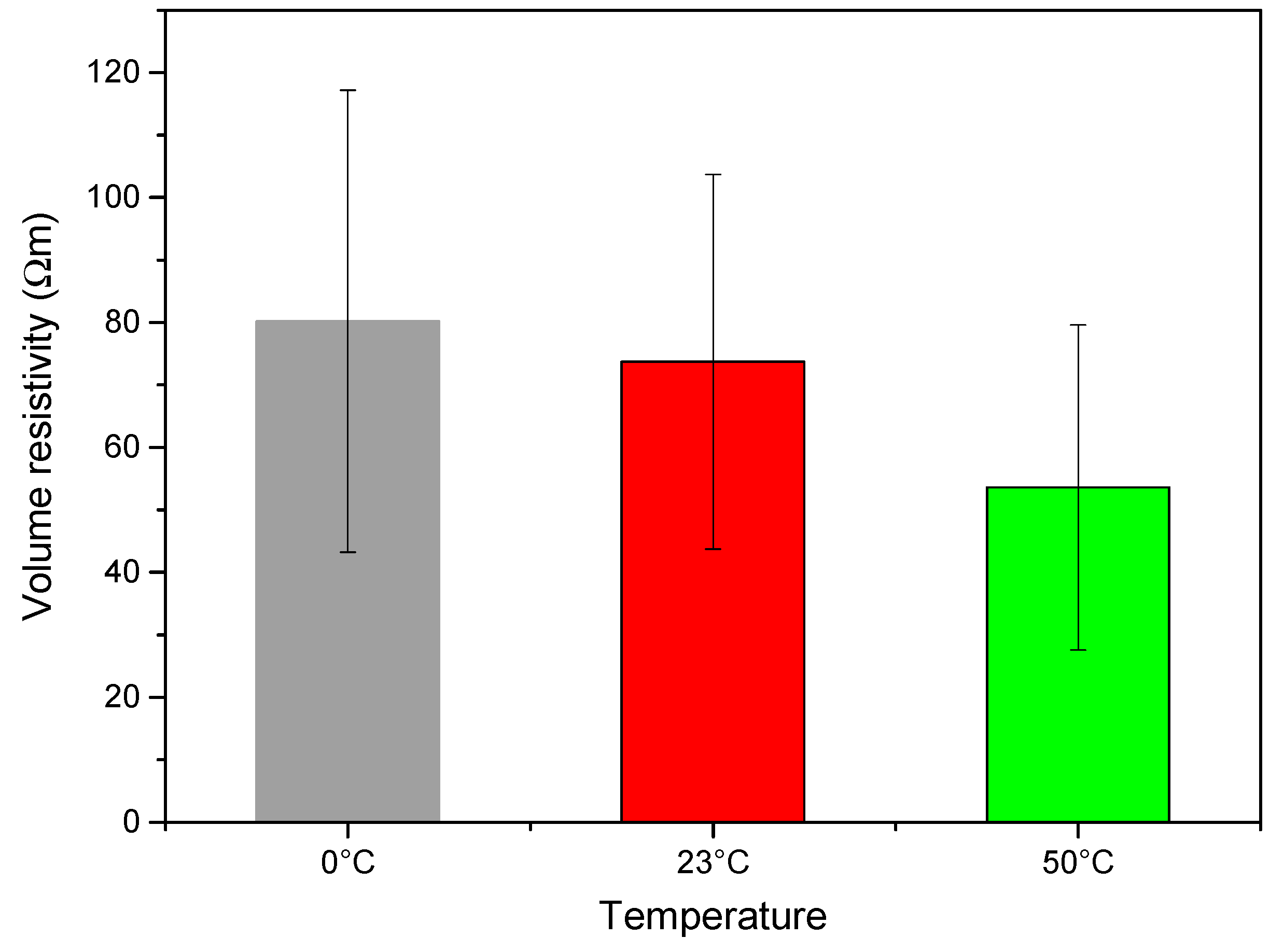
In order to evaluate the real electrical monitoring capability of the prepared laminates, electrical resisitivty measurements at three different temperatures (0 °C, 23 °C, and 50 °C) were performed by using a 2-point configuration. As shown in Figure 6, electrical volume resistivity of the EP-rGO-GF laminate is comparable to that of the rGO treated fibers (if produced according to 2A parameters shown in Table 2). This means that the presence of the matrix around the fibers does not substantially affect the conductivity behavior of the system. Considering the standard deviation values associated to these measurements, it can be concluded that the electrical resistivity of the laminates is only weakly influenced by the testing temperature with a slight decreasing trend. Therefore, the electrical behaviour of the EP-rGO-GF composite is characterized by a negative temperature coefficient (NTC) [50]. On the basis of the literature information, this behavior could be ascribed to the electron emission between the continuous interphase of rGO sheets [51,52,53]. It could be interesting to observe that, in the previous paper of our group [25], rGO based epoxy/glass composites characterized by a volume resistivity as low as 4.5 Ω·m were obtained by applying much harsher EPD conditions (i.e., GO concentration in water suspension of 0.1 wt%, applied electric filed of 10 V/cm).
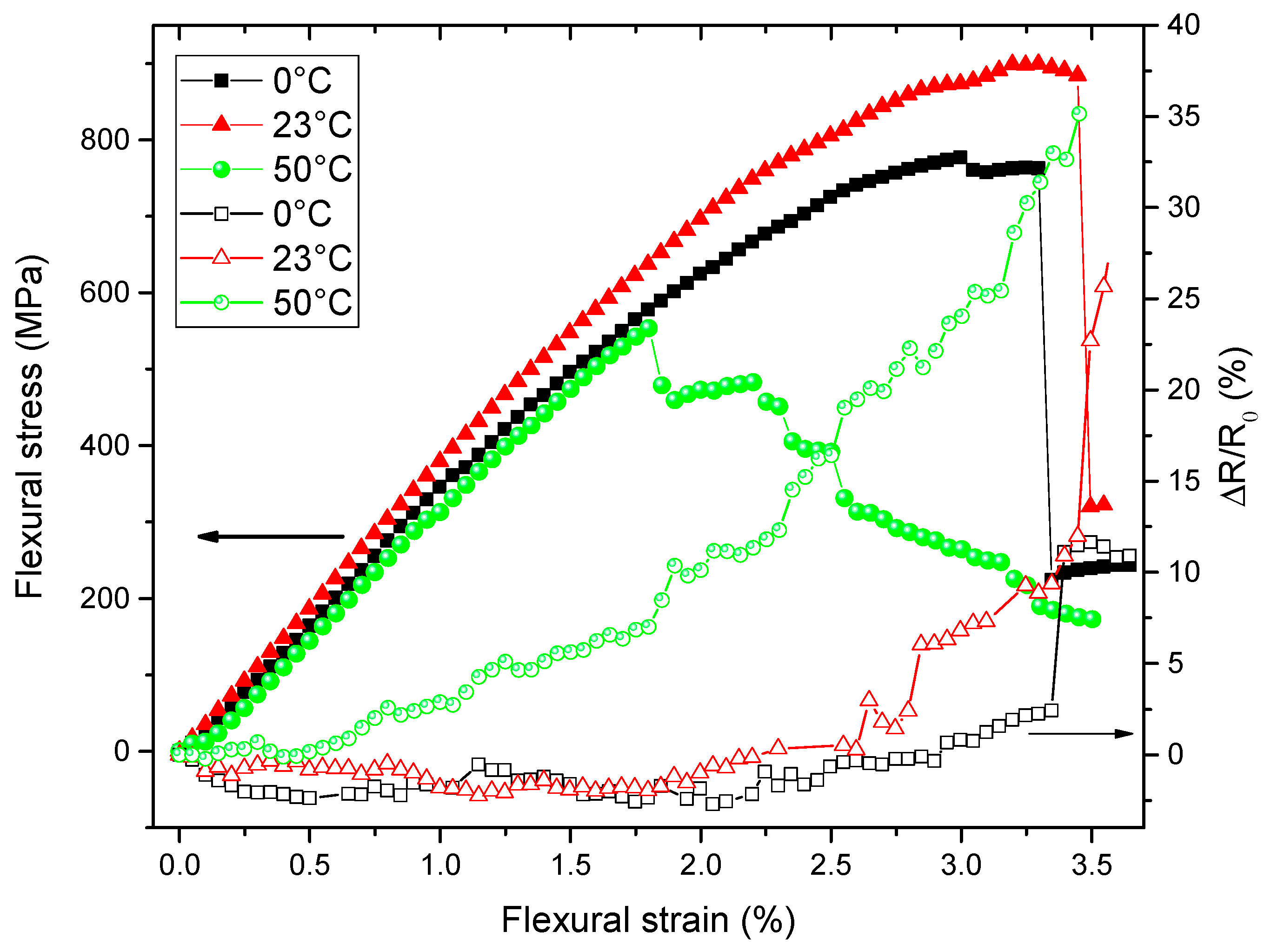
Finally, the strain/damage monitoring capabilities of EP-rGO-GF composites were tested under flexural conditions at three different temperatures. In Figure 7, the trends of the electrical resistance variation (ΔR/R0) and of the stress as a function of the applied strain are reported. It is interesting to note that as the temperature increases, the piezoresistivity of the samples is noticeably enhanced. At 0 °C and 23 °C, the resistance change is practically negligible until an applied strain of 2%. For higher strain levels, ΔR/R0 increases until the failure of the specimen occurs. At 50 °C, a more pronounced increase of ΔR/R0 with the strain can be observed, especially in the low deformation interval. These results can likely be explained by considering the NTC of EP-rGO-GF composites. In other words, a sample endowed with a higher conductivity is characterized by a better piezoresistive behaviour, and it could be thus applied for strain monitoring applications.
4. Conclusions
In this work, glass fibers were treated through electrophoretic deposition by utilizing different processing parameters. The coated fibers were then subjected to chemical reduction in order to produce a conductive coating of reduced graphene oxide (rGO) on their surface. The fibers treated with the optimized parameters (i.e., by using 0.02 wt% of GO solution deposited at 0.5 V/cm) showed the highest electrical conductivity. These fibers were then utilized to prepare composite laminates through a hand lay-up technique by using an epoxy resin as matrix. The rGO deposition on the glass fibers was responsible for the slight increase of the dynamic moduli (E’, E’’) of the composites, coupled with a noticeable enhancement of the flexural strength and of the delamination resistance. Furthermore, composites with rGO-coated glass fibers showed an electrical resistivity of about ~101 Ω·m. The EP-rGO-GF laminate was characterized by a good piezoresistive behavior under flexural conditions, and the strain monitoring sensitivity increased with the testing temperature. It was therefore demonstrated that, through a proper optimization of the EPD parameters, it is possible to produce rGO-coated glass fibers that permit the strain/damage monitoring in structural composites in a wide temperature range. Such findings could find their usefulness in applications where the temperature variation of structural composites, due to service conditions, could modify their behavior in terms of strain monitoring response.
Author Contributions
H.M., A.D., and A.P. conceived and designed the experiments; H.M. performed the experiments; H.M., A.D., and A.P. analyzed the data and wrote the paper.
Funding
This research activity has been financed by the Fondazione Cassa di Risparmio di Trento e Rovereto (CARITRO) within the project “Development of self-sensing/self-healing structural composites using graphene treated fibers” The work was also supported by the National Interuniversitary Consortium of Materials Science and Technology (INSTM).
Acknowledgments
Andrea Ruffini is gratefully acknowledged for his support to the experimental work.
Conflicts of Interest
The authors declare no conflict of interest.
References
- Pegoretti, A.; Karger-Kocsis, J. Editorial corner—A personal view Interphase engineering in polymer composites: Challenging the devil. Express Polym. Lett. 2015, 9, 838. [Google Scholar] [CrossRef]
- Jones, F.R. A Review of Interphase Formation and Design in Fibre-Reinforced Composites. J. Adhes. Sci. Technol. 2010, 24, 171–202. [Google Scholar] [CrossRef]
- Karger-Kocsis, J.; Mahmood, H.; Pegoretti, A. Recent advances in fiber/matrix interphase engineering for polymer composites. Prog. Mater. Sci. 2015, 73, 1–43. [Google Scholar] [CrossRef] [Green Version]
- Dorigato, A.; Brugnara, M.; Pegoretti, A. Novel polyamide 12 based nanocomposites for industrial applications. J. Polym. Res. 2017, 24, 96. [Google Scholar] [CrossRef]
- Dorigato, A.; Pegoretti, A. Effects of carbonaceous nanofillers on the mechanical and electrical properties of crosslinked poly(cyclooctene). Polym. Eng. Sci. 2017, 57, 537–543. [Google Scholar] [CrossRef]
- Dorigato, A.; Moretti, V.; Dul, S.; Unterberger, S.H.; Pegoretti, A. Electrically conductive nanocomposites for fused deposition modelling. Synth. Met. 2017, 226, 7–14. [Google Scholar] [CrossRef] [Green Version]
- Pegoretti, A.; Dorigato, A.; Biani, A.; Slouf, M. Cyclic olefin copolymer-silica nanocomposites foams. J. Mater. Sci. 2016, 51, 3907–3916. [Google Scholar] [CrossRef]
- Pedrazzoli, D.; Dorigato, A.; Conti, T.; Vanzetti, L.; Bersani, M.; Pegoretti, A. Liquid crystalline polymer nanocomposites reinforced with in-situ reduced graphene oxide. Express Polym. Lett. 2015, 9, 709–720. [Google Scholar] [CrossRef]
- Dorigato, A.; Sebastiani, M.; Pegoretti, A.; Fambri, L. Effect of Silica Nanoparticles on the Mechanical Performances of Poly(Lactic Acid). J. Polym. Environ. 2012, 20, 713–725. [Google Scholar] [CrossRef]
- Gupta, R.K.; Kennel, E.; Kim, K.-J. Polymer Nanocomposites Handbook; CRC Press: Boca Raton, FL, USA, 2009. [Google Scholar]
- Hua, Y.; Li, F.; Liu, Y.; Huang, G.-W.; Xiao, H.-M.; Li, Y.-Q.; Hu, N.; Fu, S.-Y. Positive synergistic effect of graphene oxide/carbon nanotube hybrid coating on glass fiber/epoxy interfacial normal bond strength. Compos. Sci. Technol. 2017, 149, 294–304. [Google Scholar] [CrossRef]
- Goh, G.D.; Dikshit, V.; Nagalingam, A.P.; Goh, G.L.; Agarwala, S.; Sing, S.L.; Wei, J.; Yeong, W.Y. Characterization of mechanical properties and fracture mode of additively manufactured carbon fiber and glass fiber reinforced thermoplastics. Mater. Des. 2018, 137, 79–89. [Google Scholar] [CrossRef]
- Sun, X.; Sun, H.; Li, H.; Peng, H. Developing polymer composite materials: Carbon nanotubes or graphene? Adv. Mater. 2013, 25, 5153–5176. [Google Scholar] [CrossRef] [PubMed]
- Chizari, K.; Arjmand, M.; Liu, Z.; Sundararaj, U.; Therriault, D. Three-dimensional printing of highly conductive polymer nanocomposites for EMI shielding applications. Mater. Today Commun. 2017, 11, 112–118. [Google Scholar] [CrossRef]
- Cataldi, P.; Ceseracciu, L.; Marras, S.; Athanassiou, A.; Bayer, I.S. Electrical conductivity enhancement in thermoplastic polyurethane-graphene nanoplatelet composites by stretch-release cycles. Appl. Phys. Lett. 2017, 110, 121904. [Google Scholar] [CrossRef]
- Kuilla, T.; Bhadra, S.; Yao, D.H.; Kim, N.H.; Bose, S.; Lee, J.H. Recent advances in graphene based polymer composites. Prog. Polym. Sci. 2010, 35, 1350–1375. [Google Scholar] [CrossRef]
- Tan, L.; Wang, C.; Zeng, M.; Fu, L. Graphene: An Outstanding Multifunctional Coating for Conventional Materials. Small 2017, 13, 1603337. [Google Scholar] [CrossRef] [PubMed]
- Cataldi, P.; Athanassiou, A.; Bayer, I. Graphene Nanoplatelets-Based Advanced Materials and Recent Progress in Sustainable Applications. Appl. Sci. 2018, 8, 1438. [Google Scholar] [CrossRef]
- Chang, L.; Friedrich, K. Enhancement effect of nanoparticles on the sliding wear of short fiber-reinforced polymer composites: A critical discussion of wear mechanisms. Tribol. Int. 2010, 43, 2355–2364. [Google Scholar] [CrossRef]
- Vlasveld, D.P.N.; Parlevliet, P.P.; Bersee, H.E.N.; Picken, S.J. Fibre-matrix adhesion in glass-fibre reinforced polyamide-6 silicate nanocomposites. Compos. Part A Appl. Sci. Manuf. 2005, 36, 1–11. [Google Scholar] [CrossRef]
- Chen, J.; Zhao, D.; Jin, X.; Wang, C.C.; Wang, D.Z.; Ge, H.Y. Modifying glass fibers with graphene oxide: Towards high-performance polymer composites. Compos. Sci. Technol. 2014, 97, 41–45. [Google Scholar] [CrossRef]
- Mahmood, H.; Tripathi, M.; Pugno, N.; Pegoretti, A. Enhancement of interfacial adhesion in glass fiber/epoxy composites by electrophoretic deposition of graphene oxide on glass fibers. Compos. Sci. Technol. 2016, 126, 149–157. [Google Scholar] [CrossRef] [Green Version]
- Ali, M.A.; Umer, R.; Khan, K.A.; Samad, Y.A.; Liao, K.; Cantwell, W. Graphene coated piezo-resistive fabrics for liquid composite molding process monitoring. Compos. Sci. Technol. 2017, 148, 106–114. [Google Scholar] [CrossRef]
- Moriche, R.; Sánchez, M.; Jiménez-Suárez, A.; Prolongo, S.G.; Ureña, A. Strain monitoring mechanisms of sensors based on the addition of graphene nanoplatelets into an epoxy matrix. Compos. Sci. Technol. 2016, 123, 65–70. [Google Scholar] [CrossRef]
- Mahmood, H.; Vanzetti, L.; Bersani, M.; Pegoretti, A. Mechanical properties and strain monitoring of glass-epoxy composites with graphene-coated fibers. Compos. Part A Appl. Sci. Manuf. 2018, 107, 112–123. [Google Scholar] [CrossRef]
- Pedrazzoli, D.; Dorigato, A.; Pegoretti, A. Monitoring the mechanical behaviour of electrically conductive polymer nanocomposites under ramp and creep conditions. J. Nanosci. Nanotechnol. 2012, 12, 4093–4102. [Google Scholar] [CrossRef] [PubMed]
- Moriche, R.; Jiménez-Suárez, A.; Sánchez, M.; Prolongo, S.G.; Ureña, A. Graphene nanoplatelets coated glass fibre fabrics as strain sensors. Compos. Sci. Technol. 2017, 146, 59–64. [Google Scholar] [CrossRef]
- Eswaraiah, V.; Balasubramaniam, K.; Ramaprabhu, S. Functionalized graphene reinforced thermoplastic nanocomposites as strain sensors in structural health monitoring. J. Mater. Chem. 2011, 21, 12626–12628. [Google Scholar] [CrossRef]
- Pedrazzoli, D.; Dorigato, A.; Pegoretti, A. Monitoring the mechanical behavior under ramp and creep conditions of electrically conductive polymer composites. Compos. Part A Appl. Sci. Manuf. 2012, 43, 1285–1292. [Google Scholar] [CrossRef]
- Wang, X.; Liu, H.; Fang, P.; Liao, L.; Pan, C.; Liew, K.M. Interface enhancement of glass fiber/vinyl ester composites with carbon nanotubes synthesized from ethanol flames. J. Nanosci. Nanotechnol. 2010, 10, 948–955. [Google Scholar] [CrossRef]
- Zhang, J.E.; Zhuang, R.C.; Liu, J.W.; Mader, E.; Heinrich, G.; Gao, S.L. Functional interphases with multi-walled carbon nanotubes in glass fibre/epoxy composites. Carbon 2010, 48, 2273–2281. [Google Scholar] [CrossRef]
- Lv, P.; Feng, Y.Y.; Zhang, P.; Chen, H.M.; Zhao, N.Q.; Feng, W. Increasing the interfacial strength in carbon fiber/epoxy composites by controlling the orientation and length of carbon nanotubes grown on the fibers. Carbon 2011, 49, 4665–4673. [Google Scholar] [CrossRef]
- Tzounis, L.; Kirsten, M.; Simon, F.; Mader, E.; Stamm, M. The interphase microstructure and electrical properties of glass fibers covalently and non-covalently bonded with multiwall carbon nanotubes. Carbon 2014, 73, 310–324. [Google Scholar] [CrossRef]
- Böger, L.; Wichmann, M.H.G.; Meyer, L.O.; Schulte, K. Load and health monitoring in glass fibre reinforced composites with an electrically conductive nanocomposite epoxy matrix. Compos. Sci. Technol. 2008, 68, 1886–1894. [Google Scholar] [CrossRef] [Green Version]
- Gao, L.; Thostenson, E.T.; Zhang, Z.; Chou, T.W. Sensing of damage mechanisms in fiber-reinforced composites under cyclic loading using carbon nanotubes. Adv. Funct. Mater. 2009, 19, 123–130. [Google Scholar] [CrossRef]
- Dorigato, A.; Pegoretti, A.; Bondioli, F.; Messori, M. Improving Epoxy Adhesives with Zirconia Nanoparticles. Compos. Interface 2010, 17, 873–892. [Google Scholar] [CrossRef]
- Dorigato, A.; Pegoretti, A. The role of alumina nanoparticles in epoxy adhesives. J. Nanopart. Res. 2011, 13, 2429–2441. [Google Scholar] [CrossRef]
- Shen, J.F.; Huang, W.S.; Wu, L.P.; Hu, Y.Z.; Ye, M.X. The reinforcement role of different amino-functionalized multi-walled carbon nanotubes in epoxy nanocomposites. Compos. Sci. Technol. 2007, 67, 3041–3050. [Google Scholar] [CrossRef]
- Thostenson, E.T.; Li, W.Z.; Wang, D.Z.; Ren, Z.F.; Chou, T.W. Carbon nanotube/carbon fiber hybrid multiscale composites. J. Appl. Phys. 2002, 91, 6034–6037. [Google Scholar] [CrossRef]
- Mei, L.; He, X.D.; Li, Y.B.; Wang, R.G.; Wang, C.; Peng, Q.Y. Grafting carbon nanotubes onto carbon fiber by use of dendrimers. Mater. Lett. 2010, 64, 2505–2508. [Google Scholar] [CrossRef]
- Bekyarova, E.; Thostenson, E.T.; Yu, A.; Kim, H.; Gao, J.; Tang, J.; Hahn, H.T.; Chou, T.W.; Itkis, M.E.; Haddon, R.C. Multiscale carbon nanotube-carbon fiber reinforcement for advanced epoxy composites. Langmuir 2007, 23, 3970–3974. [Google Scholar] [CrossRef]
- Besra, L.; Liu, M. A review on fundamentals and applications of electrophoretic deposition (EPD). Prog. Mater. Sci. 2007, 52, 1–61. [Google Scholar] [CrossRef]
- Thomas, B.; Boccaccini, A.; Shaffer, M. Multi-Walled Carbon Nanotube Coatings Using Electrophoretic Deposition (EPD). J. Am. Ceram. Soc. 2005, 88, 980–982. [Google Scholar] [CrossRef]
- Cho, J.; Konopka, K.; Rozniatowski, K.; Garcia-Lecina, E.; Shaffer, M.S.P.; Boccaccini, A.R. Characterisation of carbon nanotube films deposited by electrophoretic deposition. Carbon 2009, 47, 58–67. [Google Scholar] [CrossRef]
- Mahmood, H.; Unterberger, S.; Pegoretti, A. Tuning electrical and thermal properties in epoxy/ glass composites by graphene-based interphase. J. Compos. Sci. 2017, 1, 12. [Google Scholar] [CrossRef]
- Wang, X.; Yang, H.Y.; Song, L.; Hu, Y.; Xing, W.Y.; Lu, H.D. Morphology, mechanical and thermal properties of graphene-reinforced poly(butylene succinate) nanocomposites. Compos. Sci. Technol. 2011, 72, 1–6. [Google Scholar] [CrossRef]
- Pissis, P. Thermoset Nanocomposites for Engineering Applications; iSmithers Rapra Publishing: Shawbury, UK, 2007. [Google Scholar]
- Wei, J.; Vo, T.; Inam, F. Epoxy/graphene nanocomposites—Processing and properties: A review. RSC Adv. 2015, 5, 73510–73524. [Google Scholar] [CrossRef]
- Tripathi, M.; Mahmood, H.; Novel, D.; Iacob, E.; Vanzetti, L.; Bartali, R.; Speranza, G.; Pegoretti, A.; Pugno, N. Nanoscale friction of graphene oxide over glass-fibre and polystyrene. Compos. Part B 2018, 148, 272–280. [Google Scholar] [CrossRef]
- Traina, M.; Pegoretti, A.; Penati, A. Time-temperature dependence of the electrical resistivity of high density polyethylene—Carbon black composites. J. Appl. Polym. Sci. 2007, 106, 2065–2074. [Google Scholar] [CrossRef]
- Shao, Q.; Liu, G.; Teweldebrhan, D.; Balandin, A.A. High-temperature quenching of electrical resistance in graphene interconnects. Appl. Phys. Lett. 2008, 92, 202108. [Google Scholar] [CrossRef]
- Das, N.C.; Chaki, T.K.; Khastgir, D. Effect of processing parameters, applied pressure and temperature on the electrical resistivity of rubber-based conductive composites. Carbon 2002, 40, 807–816. [Google Scholar] [CrossRef]
- Hao, B.; Ma, Q.; Yang, S.D.; Mader, E.; Ma, P.C. Comparative study on monitoring structural damage in fiber-reinforced polymers using glass fibers with carbon nanotubes and graphene coating. Compos. Sci. Technol. 2016, 129, 38–45. [Google Scholar] [CrossRef]
Figure 1.
Representative images of glass fibers (GF) (a) as received, (b) after the EPD process, and (c) after chemical reduction.
Figure 1.
Representative images of glass fibers (GF) (a) as received, (b) after the EPD process, and (c) after chemical reduction.

Figure 2.
Scanning electron microscopy of (a) neat GF and GF-coated by reduced graphene oxide (rGO) under different processing conditions. (b) 0A, (c) 0B, (d) 0C, (e) 1A, (f) 1B, (g) 1C, (h) 2A, (i) 2B, (j) 2C.
Figure 2.
Scanning electron microscopy of (a) neat GF and GF-coated by reduced graphene oxide (rGO) under different processing conditions. (b) 0A, (c) 0B, (d) 0C, (e) 1A, (f) 1B, (g) 1C, (h) 2A, (i) 2B, (j) 2C.


Figure 3.
Scanning electron microscopy of cross-sectional view of neat GF (a and b) and GF-coated by rGO (c and d) under 2A processing condition.
Figure 3.
Scanning electron microscopy of cross-sectional view of neat GF (a and b) and GF-coated by rGO (c and d) under 2A processing condition.

Figure 4.
Optical microscopy images of (a) EP-GF and (b) EP-rGO-GF composites.

Figure 5.
Storage modulus, loss modulus, and loss tangent curves from dynamic mechanical analysis (DMA) on the prepared composites.
Figure 5.
Storage modulus, loss modulus, and loss tangent curves from dynamic mechanical analysis (DMA) on the prepared composites.

Figure 6.
Electrical volume resistivity of EP-rGO-GF composite at different temperatures.

Figure 7.
Piezoresistive behaviour of EP-rGO-GF composites under flexural conditions at three different temperatures (0 °C, 23 °C, and 50 °C). Full symbols: applied stress, open symbols: ΔR/R0 values.
Figure 7.
Piezoresistive behaviour of EP-rGO-GF composites under flexural conditions at three different temperatures (0 °C, 23 °C, and 50 °C). Full symbols: applied stress, open symbols: ΔR/R0 values.


Table 1.
Conditions of electrophoretic deposition of graphene oxide (GO) on glass fibers.
| Code. | GO Concentration in Water (wt%) | Applied Electric Field (V/cm) |
|---|---|---|
| 0A | 0.005 | 0.5 |
| 0B | 0.005 | 1.0 |
| 0C | 0.005 | 1.5 |
| 1A | 0.01 | 0.5 |
| 1B | 0.01 | 1.0 |
| 1C | 0.01 | 1.5 |
| 2A | 0.02 | 0.5 |
| 2B | 0.02 | 1.0 |
| 2C | 0.02 | 1.5 |
Table 2.
Electrical volume resistivity of the treated fibers.
| Sample | Resistivity (Ω·m) |
|---|---|
| Uncoated GF | 1.5 × 10¹⁴ |
| 0A | 6449 ± 241 |
| 0B | 5439 ± 368 |
| 0C | 2073 ± 562 |
| 1A | 1154 ± 146 |
| 1B | 887 ± 203 |
| 1C | 222 ± 54 |
| 2A | 41 ± 7 |
| 2B | 51 ± 18 |
| 2C | 52 ± 14 |
Table 3.
Density, porosity, and fiber content of the prepared composites.
| Sample | Fiber Fraction (vol%) | Theoretical Density ρt (g/cm3) | Experimental Density ρe (g/cm3) | Void Content (vol%) |
|---|---|---|---|---|
| EP | - | 1.1470 | 1.1470 ± 0.0014 | - |
| EP-GF | 65.0 | 2.1056 | 1.9960 ± 0.0068 | 5.20 ± 0.32 |
| EP-rGO-GF | 65.3 | 2.1095 | 2.0363 ± 0.0404 | 3.47 ± 1.91 |
Table 4.
Results of TGA analysis on neat epoxy and of the relative composites.
| Parameter | EP | EP-GF | EP-rGO-GF |
|---|---|---|---|
| T5% | 306.6 | 332.5 | 346.5 |
| Tonset | 335.1 | 347.0 | 332.1 |
| Td | 346.7 | 375.7 | 367.3 |
| rm | 7.35 | 77.4 | 81.6 |
T5%: temperature corresponding to 5% weight loss; Tonset: temperature corresponding to initiation of degradation; Td: temperature corresponding to maximum mass loss rate; rm: residual mass at 700 °C.
Table 5.
Flexural properties and interlaminar shear strength (ILSS) values of the prepared composites.
Table 5.
Flexural properties and interlaminar shear strength (ILSS) values of the prepared composites.
| Sample | Flexural Modulus (MPa) | Flexural Strength (MPa) | Flexural Strain at Break (%) | ILSS (MPa) |
|---|---|---|---|---|
| EP-GF | 38.2 ± 0.7 | 687 ± 55 | 2.1 ± 0.2 | 44 ± 5 |
| EP-rGO-GF | 38.6 ± 0.8 | 888 ± 22 | 3.0 ± 0.1 | 57 ± 13 |
© 2019 by the authors. Licensee MDPI, Basel, Switzerland. This article is an open access article distributed under the terms and conditions of the Creative Commons Attribution (CC BY) license (http://creativecommons.org/licenses/by/4.0/).
Share and Cite
MDPI and ACS Style
Mahmood, H.; Dorigato, A.; Pegoretti, A. Temperature Dependent Strain/Damage Monitoring of Glass/Epoxy Composites with Graphene as a Piezoresistive Interphase. Fibers 2019, 7, 17. https://0-doi-org.brum.beds.ac.uk/10.3390/fib7020017
AMA Style
Mahmood H, Dorigato A, Pegoretti A. Temperature Dependent Strain/Damage Monitoring of Glass/Epoxy Composites with Graphene as a Piezoresistive Interphase. Fibers. 2019; 7(2):17. https://0-doi-org.brum.beds.ac.uk/10.3390/fib7020017
Chicago/Turabian StyleMahmood, Haroon, Andrea Dorigato, and Alessandro Pegoretti. 2019. "Temperature Dependent Strain/Damage Monitoring of Glass/Epoxy Composites with Graphene as a Piezoresistive Interphase" Fibers 7, no. 2: 17. https://0-doi-org.brum.beds.ac.uk/10.3390/fib7020017
Note that from the first issue of 2016, this journal uses article numbers instead of page numbers. See further details here.