1. Introduction
Glass fibre (GF) is the most widely used reinforcement fibre for polymer composites due to its relatively high specific properties and low cost. Increased use across several engineering sectors has fuelled increased production with estimates of E-glass manufacture now around seven million metric tons per year [
1]. A large percentage of this GF is used in thermosetting matrices; however, the resulting composites are problematic from the manufacturing waste and end-of-life recycling perspective. Thermoset based composites often contain high contents of GF which may be considered the most valuable fraction if they could be recovered [
2]. Probably the most technologically advanced techniques for separation of fibre from matrix are thermal recycling methods [
2,
3]. Unfortunately the strength of recovered fibres is very poor; a strength loss of 70% or more is commonplace [
4,
5,
6]. Such significant strength loss precludes reuse of recovered fibre as reinforcements for composites. Depending on the methodology of recycling or thermal conditioning used, part of the strength loss may be due to physical damage of the GF surface. It has been demonstrated, however, that significant strength loss is associated only with exposure to elevated temperature [
4]. This thermal strength loss is a significant factor from approximately 450 °C; below the complete degradation temperature for most thermosetting composite matrices.
Thermal strength loss of GF is not yet fully understood but one suggested explanation has been its interaction with water [
7]. It is established that a stress corrosion mechanism weakens newly formed glass at room temperature over time [
8,
9] and this also appears to be the case for GFs [
10]. When fibres are exposed to elevated temperature in either recycling or thermal conditioning it is inevitable that water is present in the treatment atmosphere. Even if dry atmosphere is used, water is present in fibre sizings or adsorbed to the surface of the GFs themselves [
11,
12]. A strength reducing mechanism similar to stress corrosion, but acting at elevated temperature, appears to have been suggested at different times in the literature but has yet to be directly investigated.
In this work, the authors have examined the influence of water during thermal conditioning using a thermal volatilisation analyser (TVA). Samples were treated simultaneously under vacuum and at elevated temperature and the evolved volatiles were chemically analysed. This novel thermal conditioning method allowed GFs to be treated in the absence of atmospheric and surface adsorbed water for the first time and their tensile properties to then be directly measured. The results appear to not support some of the current ideas about GF strength loss.
2. Experimental Section
2.1. Materials
Boron-free E-glass (Advantex) fibres manufactured by Owens Corning Vetrotex (Granville OH, USA) were investigated in this study. These fibre rovings were produced on a pilot scale bushing as 20 kg continuous single-end square edge packages. The nominal tex of the rovings was 1200 g/km and the nominal single-fibre diameter was 17 µm. The fibres used in the study had no sizing applied during the initial manufacturing and instead had only been water sprayed using the normal cooling sprays under the bushing. Fibre rovings were subsequently dried at 105 °C for 24 h. These samples are referred to as bare or water sized, as it can be assumed that most water was removed during the subsequent drying step.
2.2. Thermal Conditioning Using Furnace
All thermal conditioning in this work was performed using single fibres. The necessity of this careful single fibre approach was to obtain reliable values of retained tensile strength which had been reported previously [
4]. Thermal conditioning of single fibres in a typical air furnace was achieved using a similar method to that employed in [
4] whereby fibres were affixed to wire frames. Rather than previously used instantaneous heating and cooling, fibres were heated at approximately 30 °C/min up to 450 °C; a 15-min isothermal was applied and then the furnace was shut off and samples cooled back to room temperature over a period of about 1 h. This process reflected the heating and cooling rates achieved using TVA.
2.3. Thermal Conditioning Using TVA
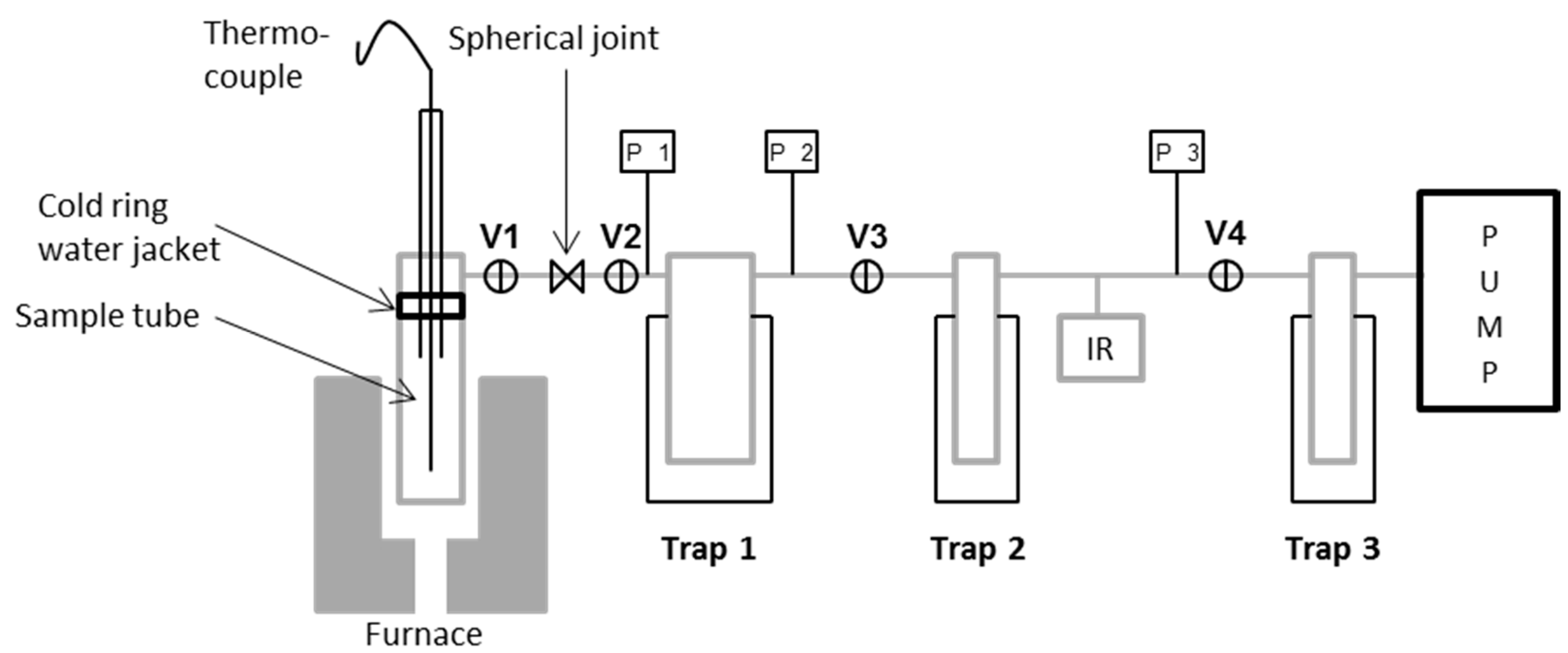
To achieve thermal conditioning of fibres while simultaneously held under vacuum a method was developed using a thermal volatilisation analyser. This technique allows the application of relatively high temperatures under vacuum and is commonly applied in polymer degradation analysis [
13]. A simplified diagram of the TVA system is shown in
Figure 1.
The apparatus consisted of a sample chamber (heated by a programmable tube furnace) connected in a series of primary and secondary liquid nitrogen cooled traps. A third trap protected the vacuum pump. The entire system was continuously pumped to the vacuum by means of a single stage rotary pump. Volatile condensable products could be collected initially in the first liquid nitrogen trap and then transferred to the second trap and subsequent gas cell for IR analysis. Linear response Pirani gauges (labelled P1, 2, 3) allowed the pressure in the system to be monitored throughout.
Before conditioning, glass fibres were mounted on a hollow quartz tube using high temperature resistant cement as indicated in
Figure 2. They were mounted to prevent contact between adjacent fibres, or between fibres and other surfaces, provided sufficient care was taken when handling. Thermal conditioning was carried out at 450 °C and the heating rate was approximately 30 °C/min until a sample temperature of 450 °C was achieved, then a 15-min isothermal was applied. The furnace was switched off and removed; the sample tube was then left to cool to room temperature over the course of approximately 1 h.
2.4. Characterisation of Volatilised Water
Characterisation of the volatilisation of water due to vacuum pre-drying at room temperature was performed using 1.3 g samples of water-sized glass fibres. Samples were placed into a sample tube, the tube head was sealed in place and the system pumped down to vacuum pressure. Due to higher than normal surface to volume ratio of the fibres (in comparison to commonly analysed TVA samples) a limited absolute vacuum pressure of 10-2 mbar was achieved after approximately 40 min. Once this pressure was reached, timing of the so-called room temperature pre-drying began.
Pre-drying periods of 0, 1 and 2 h were studied to assess the relative degree of water removed; a new GF sample was used for each case. After reaching 10
−2 mbar, a defined pre-drying period began; during which this time volatiles from the sample tube passed through the system unanalysed. Once elapsed, liquid nitrogen was placed on cold traps 1 and 2 to begin retention of volatiles for IR analysis. The sample temperature was increased at approximately 30 °C/min up to 450 °C. This combination of simultaneous temperature and vacuum removes any residual water on the GF surface as well as some hydroxyl groups [
14]. Volatiles retained were transferred to a gas-phase cell and analysed using a PerkinElmer Spectrum 100 Optica FT-IR Spectrometer. Scans were performed at a resolution of 1 cm
−1 and a background correction was taken before each measurement.
2.5. Tensile Testing
Single fibre tensile properties were obtained according to the method described in ASTM C1557-03. The details of the procedure utilised was described comprehensively by Yang and Thomason [
15]. All fibres were mounted at a gauge length of 20 mm. After each individual fibre diameter was measured by optical microscopy, the samples were tested using an Instron 3342 universal testing machine equipped with a 10 N load cell. An extension rate of 0.3 mm/min was used in all cases. The average strength values for each condition were based on at least 20 tensile tests. Tests were carried out at room temperature and approximately 50% relative humidity.
3. Results
3.1. Fibre Drying under Vacuum Using TVA
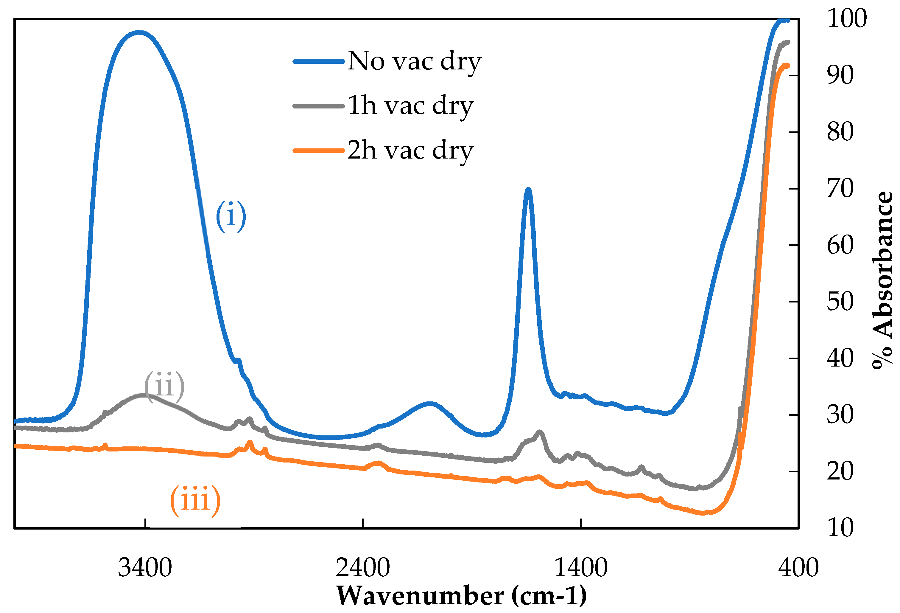
Removal of water by room temperature pre-drying under vacuum was investigated before undertaking the thermal conditioning of single fibre samples, whose tensile properties were to be measured. The same GF was used to investigate this, but in significantly greater masses than later tensile specimen thermal conditioning. This was necessary to achieve a sufficiently strong signal for IR analysis. Vacuum pre-drying was carried out for three time periods, 0, 1 or 2 h as described above, after which any remaining water (and some surface hydroxyls) were volatilised by heating. These volatiles were captured in the traps and their IR spectra are presented in
Figure 3.
Relatively simple IR spectra were obtained; this was expected given the GFs were water sized. Theoretically only peaks related to water should be found, although some organic contamination (most likely from the vacuum grease used to seal the glassware) was measured as indicated by the small peaks associated with various C-H bonds between 3000–2850 cm−1.
Curve (i) in
Figure 3 shows the IR spectrum for a sample which was not allowed to pre-dry under vacuum (‘0’ h). This represented the maximum strength of water signal that can be measured using gas cell IR following TVA. Two clear peaks in this spectrum were visible: a broad peak from approximately 3700–3000 cm
−1 and a narrow peak at about 1650 cm
−1. These are characteristic of water; the broad band corresponded to the O-H stretching vibration and the narrow peak to the O-H scissoring vibration. The apparent peak between 2000–2250 cm
−1 did not correspond to an absorbance phenomenon but was a standard feature observed in spectra demonstrating a strong water signal [
16].
Curves (ii) and (iii) showed the spectra obtained from the samples that were pre-dried under vacuum for one and two hours respectively, before then beginning to capture volatiles and heating to 450 °C. The intensity of both water peaks, compared with sample (i), was significantly reduced. Following one-hour pre-drying the maximum absorbance for the O-H stretching band decreased from approximately 97.5% to around 37.5% and for the O-H scissoring band from around 70% to 31%. Remaining absorbance peaks suggested that some water was still adsorbed to the sample after the first hour of pre-drying.
Curve (iii) showed the spectrum obtained when a fibre sample was subjected to two hours of pre-drying under vacuum. The spectrum was largely featureless, the strongest absorbance being due to C-H contamination. The broad O-H stretching peak between 3700–3000 cm−1 was eliminated and the O-H scissor peak was barely greater than the background absorbance level. This suggested that two hours of pre-drying the fibres under vacuum removed all physically adsorbed water. Upon heating to 450 °C it is possible that the remaining hydrogen bonded hydroxyl groups were removed from the sample, which would explain the persisting small O-H related absorbance. A vacuum pre-drying period of two hours was therefore selected for single fibre vacuum heat treatment experiments.
3.2. Strength of Fibres after Heat Treatment under Vacuum
The tensile properties of untreated and thermally conditioned fibres are presented in
Figure 4. Error bars indicate 95% confidence limits. The values of Young’s modulus presented were not corrected against the compliance of the system, however qualitative comparisons between the treatments applied in this study can still be made. The corrected modulus of the untreated fibres used in this study had previously been reported as 78.7 GPa [
15].
The initial fibre strength of 1.5–1.6 GPa has been established for untreated continuous bare E-glass fibre [
4]. No significant difference was found in strength between fibres heat treated either under vacuum or in air at 450 °C: they experienced a strength loss of 25–35%. The uncorrected Young’s modulus of untreated fibres was approximately 66 GPa which is in reasonable agreement with previous data [
15]. The increase in modulus due to thermal conditioning was established in the literature. The relative increase from initial value for furnace conditioned fibres at 450 °C was similar to that noted in previous work [
17], but it is interesting to note that thermal conditioning under vacuum conditions produced a significantly greater modulus increase than would be expected at 450 °C. The 15% increase may be considered representative of thermal conditioning in air at 550 °C if interpreted using data from [
17]. It is possible that the removed water had a plasticising effect on the glass structure.
4. Discussion
Previous studies of the effect of fibre heat treatment under dry, inert atmosphere in comparison with air have predominantly found no significant difference in the retained fibre strength [
5,
18,
19]. This finding was also reported here (
Figure 5), however for the first time in our work a vacuum rather than dry inert gas was used as the fibre conditioning atmosphere. Bare GFs were used therefore sizing degradation was not a factor. Careful handling and treatment of single fibres suggested that strength loss measured was due to fundamental thermal effects.
This fundamental strength loss, most significant at temperatures ≥450 °C [
4,
5], had been established in the literature but a satisfactory complete explanation of the underlying mechanisms has yet to be given. Although the bulk structure of glass fibres has been shown to change during heat treatment [
17] the failure of the fibres remains brittle in nature, therefore it may be described by the classic fracture mechanics equation.
In the equation,
σf is the failure stress,
KIc the fracture toughness,
ac the size of the critical flaw causing failure and
Y a constant related to its geometry. The strength of fibres was significantly reduced following heat treatment; implying that either fracture toughness was reduced or the flaws increased in severity, with respect to either size or shape. Little data exists on the fracture toughness of E-glass fibres, but it has been suggested that it was not changed by heat treatment [
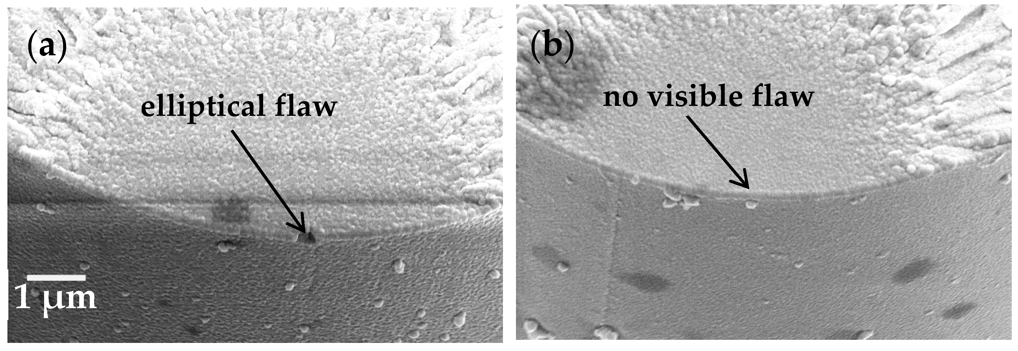
7]. If this was the case, the equation dictates that there must be an increase in the size of the critical flaw at which failure occurs, or some change whereby the geometry had an increased value of Y, for example a more elliptical shape. An SEM showing a fibre fracture surface with an elliptical flaw at the origin is shown in
Figure 5a; also presented in
Figure 5b is a fracture surface upon which the failure inducing flaw cannot be observed (a common observation in such studies and attributed to a straight-edged flaw whose dimensions cannot be resolved even at high magnification).
The subject of flaw initiation and growth in glasses have been mostly studied with respect to the strength loss that occurs with time, from the moment that glass is manufactured or that a glass fibre is drawn. This phenomenon is termed stress corrosion and numerous different mechanisms have been proposed to explain it in the literature over the past decades. The currently accepted model is based on the diffusion of water [
9]. Molecular water diffuses into a glass network and reacts with siloxane bonds to form silanols (SiOH), thereby breaking bonds in the glass structure.
A similar process, possibly accelerated at an elevated temperature, has been invoked in the literature to explain fundamental strength loss of GF due to heat treatment. The results of this study, however, have been interpreted by these authors as in opposition to this mechanism. The removal of both atmospheric and surface adsorbed water did not affect retained fibre strength, which was statistically similar to a sample treated in an air furnace.
The possibility of an alternative explanation is suggested, based on the crack tip shielding phenomenon reported for silica [
20,
21]. Water can react with strained siloxane bonds to produce two silanols as indicated in Equation (2).
In their work Wiederhorn et al. [
20] demonstrated strengthening of glass simultaneously held at an elevated temperature while exposed to high water vapour pressure. In the cases presented in our work (standard furnace or vacuum conditions) vapour pressure was low and water was more likely to leave the glass structure [
12]. This may be water from interstitial voids but could also form through the recombination of paired silanols. This process would then contribute to weakening of the glass by reducing the crack tip shielding, as it has been shown that it is the presence of silanols (especially paired) in the near surface region that contribute to the swelling of the glass structure and the generation of compressive stresses that must be overcome during fracture. This theory, then, somewhat opposes the mechanism that has been invoked in past discussions of strength loss of GFs in which the breaking of siloxane bonds at the near surface region is presumed to have a deleterious effect on tensile strength.


