Morphology Development of Polymer Blend Fibers along Spinning Line


State Key Laboratory for Modification of Chemical Fibers and Polymer Materials, College of Materials Science and Engineering, Donghua University, Shanghai 201620, China
*
Author to whom correspondence should be addressed.
Fibers 2019, 7(4), 35; https://0-doi-org.brum.beds.ac.uk/10.3390/fib7040035
Submission received: 27 February 2019
/
Revised: 9 April 2019
/
Accepted: 10 April 2019
/
Published: 25 April 2019
(This article belongs to the Special Issue Melt Spinning of Fibers)
Abstract
:Melt spinning is an efficient platform to continuously produce fiber materials with multifunctional and novel properties at a large scale. This paper briefly reviews research works that reveal the morphology development of immiscible polymer blend fibers during melt spinning. The better understanding of the formation and development of morphology of polymer blend fibers during melt spinning could help us to generate desired morphologies and precisely control the final properties of fiber materials via the melt spinning process.
1. Introduction
The blend method has been considered a promising way to achieve an in situ composite by simply mixing different components. The addition of the second component not only brings the original properties of the additive to the polymer blend but also creates new properties by tuning the structure of the polymer blend. The final properties of polymer materials rely on the morphology produced under the action of hydrodynamic and interfacial tension during melt processing. The strategy of tailoring the morphology of polymer blends aims to create a dispersed phase or second component at the desired scale and to distribute it in the desired position [1,2,3,4,5,6]. Melt spinning is a simple and efficient way to produce polymer blend fibers. However, the rheological behavior, heat transmission, force equilibrium, dynamics and crystallization of polymers are quite complex during the melt spinning of fibers. So far, the precise control of the morphology of polymer blend fibers is still a challenge.
The purpose of this paper is to review studies related to the morphology development of immiscible polymer blend fibers during melt spinning. The formation mechanism of the disperse-matrix morphology of blend fibers during melt spinning, regarding droplet deformation, break-up and coalescence, is also briefly addressed. In this case, the microrheological behavior and an extensive overview are given by Janssen [7]. Since most commonly used commercial polymers are not miscible, the situation becomes more complicated when the strong interaction between components is taken into consideration [8,9]. Therefore, we only consider fully immiscible polymer–polymer mixtures in this review.
The supramolecular structure evolution, regarding the crystal structure and orientation of polymer fibers during melt spinning, has been systemically studied by researchers based on on-line small-angle and wide-angle X-ray scattering techniques [10,11,12,13,14,15,16,17,18,19,20,21]. As far as we know, the effect that the second phase has on the supramolecular structure evolution during melt spinning is not yet fully understood; however, is beyond the scope of this review.
2. Morphology Development along the Spinning Line
Once the polymer melt is removed from the spinneret, it is quenched in cooling media (e.g., water and air), where the morphology of fibers is mainly controlled by the elongational force of the take-up action during the melt spinning process. The temperature of running filament decreases gradually along the spinning line, and the variation of temperature and temperature-related parameters (e.g., viscosity) play a vital role in the development of morphology during spinning [22]. Fundamental equations (1-D model), describing the axial distributions of diameter, velocity, temperature, stress and structures of the fiber during the melt spinning process, was proposed by Ziabicki [22], Kase et al. [23] and Han et al. [24,25,26,27] in the 1960s, and was later developed further and modified by other authors [28,29].
To study the evolution of the morphology and structure of polymer blend fibers, it is necessary to detect the second phase inside the fiber matrix, which is not easy due to the limitation of on-line measurement methods. Thus, a high-speed camera was used to record the flow of biphasic fluid and monitor the morphology evolution in a transparent tube [30]. However, optical recognition of the second phase in a polymeric matrix is not possible when the matrix is not transparent, which is common in most fiber materials. Furthermore, this technique is quite limited to the concentration of the second phase and the reflection index between polymer components. Therefore, in most research, the evaluation of the morphology development of polymer blend fibers is executed by collecting samples from the original position (usually by quenching extrudate in a low-temperature bath, and once removed, the capillary die) and take-up position. Recently, our group [31] and Tran et al. [32] both used a self-made fiber capturing device (see Figure 1), which allowed the capture of the running filament at different spinning line positions and quenched the structure of the filament at a low temperature. This was done in order to study the morphology development of blend fibers at a high resolution.
The initial morphology of polymer blend fibers usually comes from melt extrusion. The melting and mixing process can generate morphologies ranging from dispersed drops to fibers to lamella to co-continuous structures [33], see Figure 2. The initial morphology of immiscible polymer blend fibers is usually represented as a droplet-matrix or fibril-matrix morphology [31,32,34,35,36,37,38,39,40,41,42,43,44,45,46,47,48,49,50,51,52]. The strategy to produce lamellae and other morphologies is more difficult than that required for the droplet-matrix morphology since the interfacial tension tends to minimize the surface of the second phase [7]. Moreover, the formation mechanism of such a morphology during processing is not yet clear.
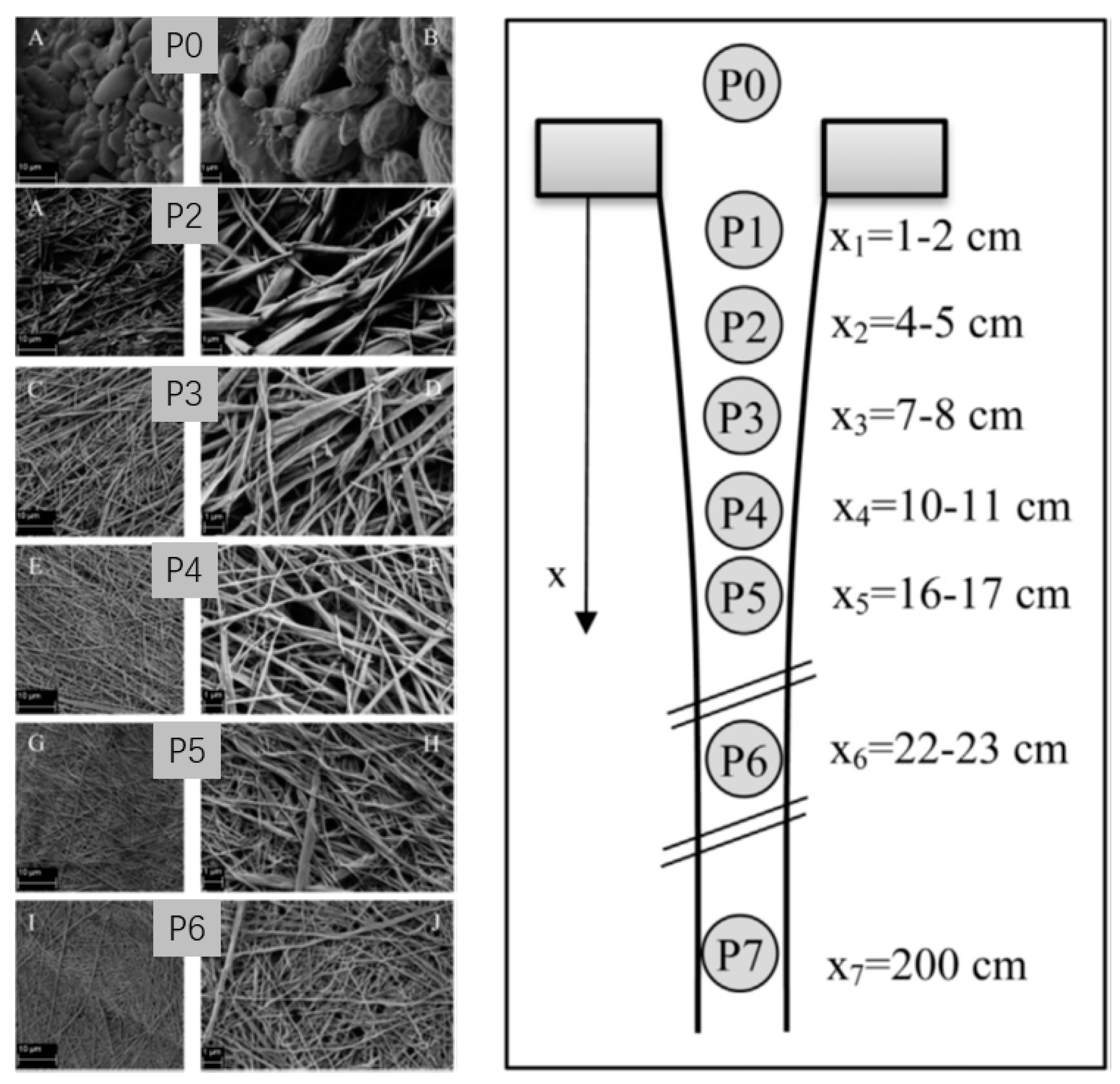
The morphology development of polymer blend fibers during melt spinning is controlled by dynamic factors (e.g., elongational force and strain rate, which are mainly dependent on the take-up action) and thermal conditions (e.g., cooling system, which affects the heat conduction and transfer of polymer blend melts) [22]. Dynamic simulation studies [22,53,54] have shown that the axis velocity and stress of the filament increase gradually along the spinning line and continue until they almost reach the point of solidification, where the polymer blend fiber is converted from the molten to the solid state. This indicates that the second phase undergoes a gradually increased elongational force in the region between the spinneret and the solidification point. Ultimately, the morphology evolution of the second phases are strongly affected by the elongational force in the fiber formation region. Experimental studies [31,32,35,36,55] have shown that the second phase is continuously stretched along the spinning line and the diameter of the second phase decreases with increasing the take-up speed due to the increasing elongational stress. A sphere or rod-like second phase can be easily stretched into a fibril-like morphology under this elongational flow field. Tran and co-authors reported the morphology development of a poly (vinyl alcohol) (PVA) and poly (lactic acid) (PLA) blend filament (the weight ratio of PVA to PLA was 70/30, the zero shear viscosity ratio of PVA to PLA was 13.3) taken-up at 50 m/min during melt spinning [32]. Figure 3 presents the morphology of the PLA phase after removing the PVA matrix at different spinning line locations. The spherical/ellipsoidal PLA domains were gradually formed into long continuous nanofibrillar structures due to the gradually increased elongational force along the spinning line. The formation of fibrillar structures is essential for the improvement of the mechanical properties of polymer blend fibers [35]. Precise morphology studies—performed in our previous studies [31,36,50]—based on the morphology analysis of cross and longitudinal sections of blend fibers revealed that the dispersed phase deformed from ellipse to nano-scale fibrils along the spinning line, as shown in Figure 4. The break-up phenomenon was observed when the interfacial tension was not strong enough to maintain the dispersed phase under the equilibrium with viscous force [36,56].
During melt spinning, the polymer melt flow presents as an unsteady flow with a shrinking fiber matrix. In some cases, the shrinking matrix compresses the droplets to enable them to migrate from the surface to the center of the matrix fiber [31]. Meanwhile, the shrinking boundary also makes the coalescence of the dispersed phase much more frequent. He and co-authors [31,57] found that there is a coalescence region combined with the droplet deformation region under the condition of high take-up velocity, as shown in Figure 5 and Figure 6. In this coalescence region, the diameter of polystyrene (PS) dispersed phases in polypropylene (PP)/PS blend fibers increased along the spinning line. This indicates that the diameter of the second phase is not always decreasing along the spinning line under elongational flow. The increase in the diameter of the dispersed phase due to the coalescence also make the elongation of the dispersed phase more pronounced and facilitates fibril formation [31,58].
The equilibrium between the break-up and coalescence of droplets makes the morphology and its development along the spinning line more complicated, especially in high concentrations and particle–particle interaction systems [9,58,59,60]. Tran and co-authors [32] showed that the dispersed phase tends to coalesce with the adjacent dispersed phase in order to form continuous long micro- or nanofibrils. When they investigated the morphological evolution of thermoplastic PVA/PLA blend filaments along the spinning line, a random morphology of the dispersed PLA phase was observed in the earlier stage, when the equilibrium between the break-up and coalescence of droplets was in a delicate balance status, which may be due to the not fully developed morphology in the extrusion capillary. Furthermore, this irregularly dispersed PLA was also stretched into micro- or nanofibrils. Yang’s study [40] showed that the fibrils or droplets at the surface of polymer blend fibers can coalesce into a continuous layer or network during melt spinning when the drawdown ratio (DDR) is high enough.
Despite the axis temperature difference, it is known that there is a non-uniform distribution of temperature along the radial direction in the melt spinning of fibers due to the heat transfer from the molten fiber to the surrounding medium [50]. The radial temperature difference in turn affects the radial viscosity and stress fields in the running filament, which can generate a hierarchical structure—such as a skin–core structure [61,62]. Furthermore, the temperature difference also influences the microrheological behavior of the second phase in polymer blend fibers [31,36,50]. Our previous research [36,38,50,63,64] found that, if a polymer blend fiber with gradient structures was produced by using this radial gradient temperature during melt spinning, it could be achieved with great ease. The gradient morphology of PP/PS blend fibers could be tailored by tuning the take-up speed and the viscosity ratio (p) of the polymer blend, as shown in Figure 7. Gradient structures with large droplets near the surface region of PP/PS blend fibers and small droplets in the center can be produced in PP/PS blend fibers with high viscosity ratios, and was found to accelerate the dye absorption of PP fiber [36]. However, a relatively uniform morphology was obtained in a matched viscosity ratio system (p ≈ 1) [64]. The dynamics of the melt spinning of PP/PS blend fibers showed that the polymer melt jets exit the spinneret at uniform temperatures [53]. As the polymer melt jets were drawn down, the polymer melt jets were cooled, with a temperature gradient in the radial direction of fiber. The transition from the central region with high temperatures to the surface region with low temperatures is shown in Figure 8. The maximum radial temperature gradients varied from 5.6 × to 12.4 × °C/m at the spinning line positions from 11.4 to 32.7 cm with regard to the various take-up velocities. The PS droplets, with higher viscosity than the PP matrix, in the center region tended to have smaller diameters than those in the surface region [31]. This radial diameter gradient was found to be a result of the radial temperature gradient since the droplets in the center region with high temperatures have a higher possibility and more time to deform into more stretched droplets or fibrils [50]. This radial diameter gradient was strengthened along the spinning line and slightly strengthened by the increasing take-up speed. However, the drastic coalescence of droplets in the center of fibers at a high take-up speed results in a weakening of the radial gradients of droplets. The dispersed phases near the surface region can act as a functional additive to improve the surface properties of normal fibers. Dan and co-authors [6] showed that PS dispersed phases near the fiber surface were aligned along the fiber axis and formed nano-channels after removing said PS phases, as shown in Figure 9. This could be a possible way to produce a functional fiber with good surface properties and novel optical properties.
3. Mechanism of Morphology Development
An essential aspect of the formation mechanism of a dispersed-matrix morphology in polymer blends is the dispersion of one liquid in another. The morphology of polymer blend fibers highly depends on the microrheological behavior of the second phase, including deformation, break-up, coalescence and migration under the action in elongational flow. In particular, the time scales of the distinct microrheological processes have to be considered to verify whether the available process time suffices for a specific event to occur [7].
The deformation of a dispersed droplet is governed by the viscosity ratio p, the ratio of the viscosity of dispersed phase to the viscosity of matrix and the capillary number , which expresses the ratio between viscous force and interfacial tension, according to Taylor’s theory [65,66].
where is the elongational rate, is the radius of the initial droplet and the interfacial tension between two polymers. The deformation degree of the dispersed phase is usually defined as:
where L is the length of the major axis, B is the length of the minor axis. Taylor presented two cases of the deformation expressions—when interfacial forces dominate and when viscous effects dominate. Cox [67] then extended Taylor’s theory to the full range of the viscosity ratio under elongational flow:
where is the flow type constant, in plane hyperbolic flow fields, in the uniaxial elongational flow field. However, Taylor and Cox’s theories are limited to small deformation cases with medium or high viscosity ratio systems. When discussing low viscosity ratio polymer blends, the dispersed phases can be stretched into fine fibrils. Meanwhile, the small deformation theory cannot predict the deformation and break-up of fibrils precisely [68]. In 1964, Taylor proposed a large deformation theory intended to describe a slender droplet in four roller axisymmetric extension fields. However, this large deformation theory is limited to low viscosity ratio and low cases. Acrivos et al. [69] extended the large deformation theory into droplet deformation in uniaxial elongational flow, for which the relation between and droplet deformation can be expressed as:
When the droplet deformation is similar to the deformation of the matrix, as shown in Figure 10, the affine deformation of droplet can be described as:
where () is the elongation stress.
Above a critical number, , the viscous force overrules the interfacial tension and no stable equilibrium droplet shape exists. The droplet is stretched and finally breaks apart. can be experimentally determined by increasing the elongational rate to evaluate whether or not the droplet shape remains stable for a considerable period of time [7]. The of the droplet in the elongational flow is a function of the viscosity ratio and can be expressed as Equation (6) according to Grace’s study [70].
There are three types of break-up that can be found in experimental studies: stepwise, transient, and edge break-up mechanisms as shown in Figure 11 [71,72]. Stepwise break-up usually happens in the case of low , wherein the mother droplet break-up converts into two same droplets when . The deformation and break-up of droplets can be predicted when the reduced capillary number (see Equation (7)) based on Huneault’s criteria [73] is taken into account. According to Huneault’s certificate, droplets cannot deform in the case of . Droplets deform but not break-up in the case of ; droplets deform and then split into two primary droplets for ; and droplets deform into fibrils and disintegration when .
During the break-up of extended fibrils, the waves of distorted interfacial surfaces are continuously stretched. Break-up occurs as soon as the amplitude of a disturbance of interface is magnified to such an extent that it equals the continuously decreasing mean thread radius [7]. The total break-up time is expressed as:
where is the critical time where the thread radius has decreased to the critical radius of break-up and is the growth time from critical time to the moment break-up occurs. is the stretching efficiency, in 2-D elongational flow and in 3-D elongational flow. , and can be determined by using the method described in Reference [7].
The above models suggest that the morphology of polymer blend fibers could be predicted based on the melt spinning dynamics simulated under some simple conditions [50,56,68,74]. The droplet deformation theory was first adopted by Padsalgikar et al. [68] to simulate the diameter of dispersed PP droplets along the spinning line in PS/PP blend fibers based on Taylor and Cox’s theories. The simulated values correlated with the measured values at the low take-up speed range from 125 to 250 m/min. Song et al. [56] adopted similar methods and predicted the diameter of Liquid crystalline polymer (LCP) droplets in polyester (PET)/LCP blend fibers. The simulated values were found to be about 12% to 33% smaller than the measured diameter. Pan et al. [50] studied the PS droplet deformation in a PP matrix during melt spinning. Delaby’s affine deformation model [75,76,77] was selected to simulate the diameter of the dispersed PS phase, based on Huneault’s certificate, and again displayed signs of correlation between predicted and measured values at relatively low take-up velocities. However, the prediction of the morphology of polymer blend fibers becomes much more challenging when the strong interaction between the dispersed phases is taken into consideration. He et al. [74] also studied the deformation, coalescence and breakup of thermotropic liquid-crystalline polymer (TLCP) drops in poly(ethylene naphthalate) (PEN)/TLCP Vectra A950 blend at the take-up speed of 300 m/min by using affine deformation theory. However, neither the degree of TLCP droplets deformation nor the fundamental question of the difference between simulated and measured morphology was further illustrated. From the existing few papers related to the simulation of the morphology of polymer blend fibers, droplet deformation theory enables the prediction of the diameter of the dispersed phase at low take-up velocities. However, when the coalescence effect is non-negligible, the precise predict of droplet morphology is not possible.
The flow-induced coalescence of droplets is a complex phenomenon and is mostly studied in shear flow, where droplets with different coordinates in the direction of the velocity gradient collide [9], as shown in Figure 12. The course of coalescence usually has three steps: (1) the approach and collision of droplets; (2) the rupture of the matrix film between two approaching droplets; (3) the drainage of the matrix film. It is difficult to find further research on the coalescence of droplets in elongational flow. However, the current coalescence theory of droplets is limited to a low shear rate range and low concentration blends. Many problems have not yet been studied, and most theories focus on the coalescence between sphere droplets, which is not common in the elongational flow. Most research neglects the effect of other droplets on the collision droplet pairs [9].
4. Conclusions and Outlooks
In this brief and introductory review, we have expressed current understandings of the morphology development of polymer blend fibers during melt spinning. Yet, current studies do not supply sufficient knowledge to cover all conditions, e.g., the full range of the viscosity ratio and the volume fraction, or the wide range of the take-up speed, due to the limitations of the precise characterization of morphology. In order to gain more insight into the formation mechanisms of morphology during melt spinning, we have drawn attention to the microrheological behavior of the second phase in elongational flow. Current research demonstrates that the microrheological theory will continue to evolve and become more popular in morphology simulation during melt processing. However, for more concentrated systems and high strain rate conditions, a complete understanding of morphology development in elongational flow has not yet been obtained. That being said, with the progress in theoretical and experimental techniques, it will perhaps be possible to design polymer materials with novel structures at desired scales and positions in the future.
Author Contributions
Conceptualization and methodology, L.C.; visualization, D.P.; investigation and resources, H.H.
Funding
This research received no external funding.
Acknowledgments
The authors thank Yifei Zhou and Senlin Hong for their kind help with the collection of information.
Conflicts of Interest
The authors declare no conflict of interest.
References
- Catlow, C.R.A. The structural science of functional materials. IUCrJ 2018, 5, 1–3. [Google Scholar] [CrossRef] [PubMed] [Green Version]
- Gooneie, A.; Schuschnigg, S.; Holzer, C. A Review of Multiscale Computational Methods in Polymeric Materials. Polymers 2017, 9, 16. [Google Scholar] [CrossRef] [PubMed]
- Gooneie, A.; Simonetti, P.; Salmeia, K.A.; Gaan, S.; Hufenus, R.; Heuberger, M.P. Enhanced PET processing with organophosphorus additive: Flame retardant products with added-value for recycling. Polym. Degrad. Stab. 2019, 160, 218–228. [Google Scholar] [CrossRef]
- Liang, Y.; Li, L.; Scott, R.A.; Kiick, K.L. Polymeric Biomaterials: Diverse Functions Enabled by Advances in Macromolecular Chemistry. Macromolecules 2017, 50, 483–502. [Google Scholar] [CrossRef] [PubMed] [Green Version]
- Polymeropoulos, G.; Zapsas, G.; Ntetsikas, K.; Bilalis, P.; Gnanou, Y.; Hadjichristidis, N. 50th Anniversary Perspective: Polymers with Complex Architectures. Macromolecules 2017, 50, 1253–1290. [Google Scholar] [CrossRef]
- Pan, D.; Hufenus, R.; Qin, Z.; Chen, L.; Gooneie, A. Tailored Gradient Morphologies and Anisotropic Surface Patterns in Polymer Blends. Macromol. Mater. Eng. 2018, 304, 1800601. [Google Scholar] [CrossRef]
- Janssen, J.M.H. Emulsions: The Dynamics of Liquid–Liquid Mixing; Wiley-VCH Verlag GmbH & Co. KGaA: Eindhoven, UK, 2006. [Google Scholar]
- Chen, D.; Liu, F.; Zhang, Y.; Zhang, Y.; Zhou, H. Simulation of dispersed phase evolution for immiscible polymer blends in injection molding. Eng. Comput. 2017, 34, 2311–2329. [Google Scholar] [CrossRef]
- Fortelny, I. Coalescence in polymer blends: Solved and open problems. Macromol. Symp. 2000, 158, 137–147. [Google Scholar] [CrossRef]
- Cakmak, M.; Teitge, A.; Zachmann, H.G.; White, J.L. On-line small-angle and wide-angle X-ray scattering studies on melt-spinning poly(vinylidene fluoride) tape using synchrotron radiation. J. Polym. Sci. Part B Polym. Phys. 1993, 31, 371–381. [Google Scholar] [CrossRef]
- Dees, J.R.; Spruiell, J.E. Structure development during melt spinning of linear polyethylene fibers. J. Appl. Polym. Sci. 1974, 18, 1053–1078. [Google Scholar] [CrossRef]
- Ellison, M.S.; Lopes, P.E.; Pennington, W.T. In-Situ X-Ray Characterization of Fiber Structure During Melt Spinning. J. Eng. Fiber Fabr. 2008, 3, 10–21. [Google Scholar] [CrossRef]
- Katayama, K.; Nakamura, K.; Amano, T. Structural formation during melt spinning process. Kolloid-Z. Polym. 1968, 226, 125–134. [Google Scholar] [CrossRef]
- Kolb, R.; Seifert, S.; Stribeck, N.; Zachmann, H.G. Investigation of the high speed spinning process of poly(ethylene terephthalate) by means of synchrotron X-ray diffraction. Polymer 2000, 41, 2931–2935. [Google Scholar] [CrossRef] [Green Version]
- Kolb, R.; Seifert, S.; Stribeck, N.; Zachmann, H.G. Simultaneous measurements of small- and wide-angle X-ray scattering during low speed spinning of poly(propylene) using synchrotron radiation. Polymer 2000, 41, 1497–1505. [Google Scholar] [CrossRef] [Green Version]
- Lopes, P.E.; Ellison, M.S.; Pennington, W.T. In situX-ray characterisation of isotactic polypropylene during melt spinning. Plast. Rubber Compos. 2013, 35, 294–300. [Google Scholar] [CrossRef]
- Samon, J.M.; Schultz, J.M.; Hsiao, B.S. Structure development in the early stages of crystallization during melt spinning. Polymer 2002, 43, 1873–1875. [Google Scholar] [CrossRef]
- Samon, J.M.; Schultz, J.M.; Hsiao, B.S.; Khot, S.; Johnson, H.R. Structure development during the melt spinning of poly(oxymethylene) fiber. Polymer 2001, 42, 1547–1559. [Google Scholar] [CrossRef]
- Samon, J.M.; Schultz, J.M.; Wu, J.; Hsiao, B.; Yeh, F.; Kolb, R. Study of the structure development during the melt spinning of nylon 6 fiber by on-line wide-angle synchrotron X-ray scattering techniques. J. Polym. Sci. Pol. Phys. 1999, 37, 1277–1287. [Google Scholar] [CrossRef]
- Schultz, J.M.; Hsiao, B.S.; Samon, J.M. Structural development during the early stages of polymer melt spinning by in-situ synchrotron X-ray techniques. Polymer 2000, 41, 8887–8895. [Google Scholar] [CrossRef]
- Spruiell, J.E.; White, J.L. Structure development during polymer processing: Studies of the melt spinning of polyethylene and polypropylene fibers. Polym. Eng. Sci. 1975, 15, 660–667. [Google Scholar] [CrossRef]
- Ziabicki, A. Fundamentals of Fibre Formation: The Science of Fibre Spinning and Drawing; Wiley: New York, NY, USA, 1976. [Google Scholar]
- Kase, S.; Matsuo, T. Studies on Melt Spinning. I. Fundamental Equations on the Dynamics of Melt Spinning. J. Polym. Sci. Part A Polym. Chem. 2010, 3, 2541–2554. [Google Scholar] [CrossRef]
- Dae Han, C.; Lamonte, R.R. Studies on Melt Spinning. I. Effect of Molecular Structure and Molecular Weight Distribution on Elongational Viscosity. Trans. Soc. Rheol. 1972, 16, 447–472. [Google Scholar] [CrossRef]
- Han, C.D. A theoretical study on fiber spinnability. Rheol. Acta 1970, 9, 355–365. [Google Scholar] [CrossRef]
- Han, C.D.; Lamonte, R.R.; Shah, Y.T. Studies on melt spinning. III. Flow instabilities in melt spinning: Melt fracture and draw resonance. J. Appl. Polym. Sci. 1972, 16, 3307–3323. [Google Scholar] [CrossRef]
- Lamonte, R.R.; Han, C.D. Studies on melt spinning. II. Analysis of the deformation and heat transfer processes. J. Appl. Polym. Sci. 1972, 16, 3285–3306. [Google Scholar] [CrossRef]
- Shimizu, J.; Okui, N.; Imai, Y. High-speed melt spinning of isotactic polypropylene fibers: Crystallization mechanism in the spinline and fiber structure and properties. Sen’i Gakkaishi 1979, 35, T405–T412. [Google Scholar] [CrossRef]
- George, H.H. Model of steady-state melt spinning at intermediate take-up speeds. Polym. Eng. Sci. 1982, 22, 292–299. [Google Scholar] [CrossRef]
- Heuberger, M.; Gottardo, L.; Dressler, M.; Hufenus, R. Biphasic fluid oscillator with coaxial injection and upstream mass and momentum transfer. Microfluid Nanofluid. 2015, 19, 653–663. [Google Scholar] [CrossRef] [Green Version]
- He, H.; Chen, L.; Zhang, Y.; Hong, S.; Zhou, Y.; Zhu, M. Studies on melt spinning of sea-island fibers. I. morphology evolution of polypropylene/polystyrene blend fibers. Fibers Polym. 2014, 15, 1941–1949. [Google Scholar] [CrossRef]
- Tran, N.H.A.; Brünig, H.; Boldt, R.; Heinrich, G. Morphology development from rod-like to nanofibrillar structures of dispersed poly (lactic acid) phase in a binary blend with poly (vinyl alcohol) matrix along the spinline. Polymer 2014, 55, 6354–6363. [Google Scholar] [CrossRef]
- Macosko Christopher, W. Morphology development and control in immiscible polymer blends. Macromol. Symp. 2000, 149, 171–184. [Google Scholar] [CrossRef]
- Liang, B.; Pan, L.; He, X. Structure and properties of blend fibers from poly(ethylene terephthalate) and liquid crystalline polymer. J. Appl. Polym. Sci. 1997, 66, 217–224. [Google Scholar] [CrossRef]
- Grasser, W.; Schmidt, H.W.; Giesa, R. Fibers spun from poly(ethylene terephthalate) blended with a thermotropic liquid crystalline copolyester with non-coplanar biphenylene units. Polymer 2001, 42, 8517–8527. [Google Scholar] [CrossRef]
- Xing, Q.; Zhu, M.; Wang, Y.; Chen, Y.; Zhang, Y.; Pionteck, J.; Adler, H.J. In situ gradient nano-scale fibril formation during polypropylene (PP)/polystyrene (PS) composite fine fiber processing. Polymer 2005, 46, 5406–5416. [Google Scholar] [CrossRef]
- Pan, Z.; Chen, Y.; Zhu, M.; Jiang, C.; Xu, Z.; Lu, W.; Pionteck, J. The non-uniform phase structure in blend fiber. II. The migration phenomenon in melt spinning. Fibers Polym. 2010, 11, 625–631. [Google Scholar] [CrossRef]
- Pan, Z.; Zhu, M.; Chen, Y.; Chen, L.; Wu, W.; Yu, C.; Xu, Z.; Cheng, L. The variation of fibrils’ number in the sea-island fiber -low density polyethylene/polyamide 6. Fibers Polym. 2010, 11, 494–499. [Google Scholar] [CrossRef]
- Tavanaie, M.A.; Shoushtari, A.M.; Goharpey, F. Polypropylene/poly (butylene terephthalate) melt spun alloy fibers dyeable with carrier-free exhaust dyeing as an environmentally friendlier process. J. Clean. Prod. 2010, 18, 1866–1871. [Google Scholar] [CrossRef]
- Yang, J.; White, J.L.; Jiang, Q. Phase morphology development in a low interfacial tension immiscible polyolefin blend during die extrusion and melt spinning. Polym. Eng. Sci. 2010, 50, 1969–1977. [Google Scholar] [CrossRef]
- Li, M.; Xiao, R.; Sun, G. Formation and morphology development of poly(butylene terephthalate) nanofibers from poly(butylene terephthalate)/cellulose acetate butyrate immiscible blends. Polym. Eng. Sci. 2011, 51, 835–842. [Google Scholar] [CrossRef]
- Li, M.F.; Xiao, R.; Sun, G. Morphology development and size control of poly(trimethylene terephthalate) nanofibers prepared from poly(trimethylene terephthalate)/cellulose acetate butyrate in situ fibrillar composites. J. Mater. Sci. 2011, 46, 4524–4531. [Google Scholar] [CrossRef] [Green Version]
- Soroudi, A.; Skrifvars, M. The influence of matrix viscosity on properties of polypropylene/polyaniline composite fibers-Rheological, electrical, and mechanical characteristics. J. Appl. Polym. Sci. 2011, 119, 2800–2807. [Google Scholar] [CrossRef]
- Soroudi, A.; Skrifvars, M.; Liu, H. Polyaniline-polypropylene melt-spun fiber filaments: The collaborative effects of blending conditions and fiber draw ratios on the electrical properties of fiber filaments. J. Appl. Polym. Sci. 2011, 119, 558–564. [Google Scholar] [CrossRef]
- Tavanaie, M.A.; Shoushtari, A.M.; Goharpey, F.; Mojtahedi, M.R. Matrix-fibril morphology development of polypropylene/poly(butylenes terephthalate) blend fibers at different zones of melt spinning process and its relation to mechanical properties. Fibers Polym. 2013, 14, 396–404. [Google Scholar] [CrossRef]
- Dehghan, N.; Tavanaie, M.A.; Payvandy, P. Morphology study of nanofibers produced by extraction from polymer blend fibers using image processing. Korean J. Chem. Eng. 2015, 32, 1928–1937. [Google Scholar] [CrossRef]
- Sugawara, K.; Ikaga, T.; Kim, K.H.; Ohkoshi, Y.; Okada, K.; Masunaga, H.; Kanaya, T.; Masuda, M.; Maeda, Y. Fiber structure development in PS/PET sea-island conjugated fiber during continuous laser drawing. Polymer 2015, 79, 37–46. [Google Scholar] [CrossRef] [Green Version]
- Li, L.; Huang, W.; Wang, B.; Wei, W.; Gu, Q.; Chen, P. Properties and structure of polylactide/poly (3-hydroxybutyrate-co-3-hydroxyvalerate) (PLA/PHBV) blend fibers. Polymer 2015, 68, 183–194. [Google Scholar] [CrossRef]
- Zhang, P.P.; Xu, D.D.; Xiao, R. Morphology development and size control of PA6 nanofibers from PA6/CAB polymer blends. J. Appl. Polym. Sci. 2015, 132, 42184. [Google Scholar] [CrossRef]
- Pan, D.; Chen, L.; He, H.; Deng, K.; Qin, Z. Deformation of dispersed polystyrene droplets in immiscible polypropylene/polystyrene blend fibers under uniaxial elongational flow. Fibers Polym. 2016, 17, 1343–1351. [Google Scholar] [CrossRef]
- Tran Nguyen Hoai, A.; Brünig, H.; Auf der Landwehr, M.; Vogel, R.; Pionteck, J.; Heinrich, G. Controlling micro- and nanofibrillar morphology of polymer blends in low-speed melt spinning process. Part II: Influences of extrusion rate on morphological changes of a PLA/PVA blend through a capillary die. J. Appl. Polym. Sci. 2016, 133, 1–10. [Google Scholar]
- Ayad, E.; Cayla, A.; Rault, F.; Gonthier, A.; Campagne, C.; Devaux, E. Effect of Viscosity Ratio of Two Immiscible Polymers on Morphology in Bicomponent Melt Spinning Fibers. Adv. Polym. Technol. 2018, 37, 1134–1141. [Google Scholar] [CrossRef]
- Chen, L.; He, H.; Zhang, Y.; Chen, Y.; Zhu, M. Studies on melt spinning of sea-island fibers. II. Dynamics of melt spinning of polypropylene/polystyrene blend fibers. Fibers Polym. 2015, 16, 449–462. [Google Scholar] [CrossRef]
- Tran, N.H.A.; Brunig, H.; Heinrich, G. Controlling micro- and nanofibrillar morphology of polymer blends in low-speed melt spinning process. Part I. Profiles of PLA/PVA-filament parameters along the spinline. J. Appl. Polym. Sci. 2016, 133, 47. [Google Scholar] [CrossRef]
- Tran, N.H.A.; Brunig, H.; der Landwehr, M.A.; Heinrich, G. Controlling micro- and nanofibrillar morphology of polymer blends in low-speed melt spinning process. Part III: Fibrillation mechanism of PLA/PVA blends along the spinline. J. Appl. Polym. Sci. 2016, 133, 48. [Google Scholar] [CrossRef]
- Song, C.H.; Isayev, A.I. LCP droplet deformation in fiber spinning of self-reinforced composites. Polymer 2001, 42, 2611–2619. [Google Scholar] [CrossRef]
- Pan, D.; Chen, L.; Qin, Z.; Zhu, M. The Evolution and Formation Mechanism of Gradient Structure During Melt Spinning of Blend Fiber. In Proceedings of the Fiber Society 2017 Spring Conference: Next Generation Fibers for Smart Products, Aachen, Germany, 17–19 May 2017; p. 122. [Google Scholar]
- GonzalezNunez, R.; DeKee, D.; Favis, B.D. The influence of coalescence on the morphology of the minor phase in melt-drawn polyamide-6/HDPE blends. Polymer 1996, 37, 4689–4693. [Google Scholar] [CrossRef]
- Sundararaj, U.; Macosko, C.W. Drop Breakup and Coalescence in Polymer Blends—The Effects of Concentration and Compatibilization. Macromolecules 1995, 28, 2647–2657. [Google Scholar] [CrossRef]
- Chesters, A.K. The Modeling of Coalescence Processes in Fluid Liquid Dispersions—A Review of Current Understanding. Chem. Eng. Res. Des. 1991, 69, 259–270. [Google Scholar]
- Shimizu, J.; Okui, N.; Kikutani, T. High speed melt spinning of poly(ethylene terephthalate) radial variation across fibers. Sen’i Gakkaishi 1981, 37, T135–T142. [Google Scholar] [CrossRef]
- Konda, A.; Toriumi, K.; Nakajima, T. Generation of skin-core structure in poly(ethylene terephthalate) fiber upon drawing hot water. Sen’i Gakkaishi 1985, 41, T530–T538. [Google Scholar] [CrossRef]
- Pan, Z.; Zhu, M.; Chen, Y.; Chen, L.; Sun, B.; Yu, H.; Jiang, C.; Xu, Z. The non-uniform phase structure in blend fiber. I. Non-uniform deformation of the dispersed phase in melt spinning. Fibers Polym. 2010, 11, 249–257. [Google Scholar] [CrossRef]
- He, H.; Chen, L.; Sun, S.; Wang, T.; Zhang, Y.; Zhu, M. Study on the matrix-fibril morphologies of polypropylene/polystyrene blends under non-isothermal uniaxial elongational flow. Fibers Polym. 2014, 15, 744–752. [Google Scholar] [CrossRef]
- Taylor, G.I. The Formation of Emulsions in Definable Fields of Flow. Proc. R. Soc. A Math. Phys. Eng. Sci. 1934, 146, 501–523. [Google Scholar] [CrossRef] [Green Version]
- Taylor, G.I. The Viscosity of a Fluid Containing Small Drops of Another Fluid. Proc. R. Soc. A Math. Phys. Eng. Sci. 1932, 138, 41–48. [Google Scholar] [CrossRef] [Green Version]
- Cox, R.G. The deformation of a drop in a general time-dependent fluid flow. J. Fluid Mech. 1969, 37, 601–623. [Google Scholar] [CrossRef]
- Padsalgikar, A.D.; Ellison, M.S. Modeling droplet deformation in melt spinning of polymer blends. Polym. Eng. Sci. 1997, 37, 994–1002. [Google Scholar] [CrossRef]
- Acrivos, A.; Lo, T.S. Deformation and breakup of a single slender drop in an extensional flow. J. Fluid Mech. 1978, 86, 641–672. [Google Scholar] [CrossRef]
- Grace, H.P. Dispersion phenomena in high viscosity immiscible fluid systems and application of static mixers as dispersion devices in such systems. Chem. Eng. Commun. 1982, 14, 225–277. [Google Scholar] [CrossRef]
- Janssen, J.M.H.; Meijer, H.E.H. Droplet Breakup Mechanisms—Stepwise Equilibrium Versus Transient Dispersion. J. Rheol. 1993, 37, 597–608. [Google Scholar] [CrossRef]
- Barai, N.; Mandal, N. Breakup modes of fluid drops in confined shear flows. Phys. Fluids. 2016, 28, 073302. [Google Scholar] [CrossRef]
- Huneault, M.A.; Shi, Z.H.; Utracki, L.A. Development of polymer blend morphology during compounding in a twin-screw extruder. Part IV A new computational model with coalescence. Polym. Eng. Sci. 1995, 35, 115–127. [Google Scholar] [CrossRef]
- He, X.; Cox, C.L.; Ellison, M.S. Simulation of TLCP Deformation During Isothermal Melt Spinning of In Situ Composite Fibers. J. Macromol. Sci. Part B 2004, 43, 309–328. [Google Scholar] [CrossRef]
- Delaby, I.; Froelich, D.; Muller, R. Droplet deformation in immiscible polymerblends during transient uniaxial elongational flow. Macromol. Symp. 1995, 100, 131–135. [Google Scholar] [CrossRef]
- Delaby, I.; Ernst, B.; Germain, Y.; Muller, R. Droplet deformation in polymer blends during uniaxial elongational flow: Influence of viscosity ratio for large capillary numbers. J. Rheol. 1994, 38, 1705–1720. [Google Scholar] [CrossRef]
- Delaby, I.; Ernst, B.; Muller, R. Drop deformation during elongational flow in blends of viscoelastic fluids. Small deformation theory and comparison with experimental results. Rheol. Acta 1995, 34, 525–533. [Google Scholar] [CrossRef]
Figure 1.
Schematic diagram of the capture device made by our group.

Figure 2.
Schematic of morphologies which can produced by polymer–polymer melt blending [33]. Reused with permission from W. Macosko Christopher, Macromolecular Symposia; published by John Wiley and Sons, 2000.
Figure 2.
Schematic of morphologies which can produced by polymer–polymer melt blending [33]. Reused with permission from W. Macosko Christopher, Macromolecular Symposia; published by John Wiley and Sons, 2000.

Figure 3.
SEM images of poly (lactic acid) (PLA) domains at different spinning line positions according to the schematic view of the filament capturing diagram, which was shown on the right side of Figure 3: P0 (A and B), P2 (A and B), P3 (C and D), P4 (E and F), P5 (G and H), P6 (I and J) [32]. Reproduced with permission from Tran, N.H.A.; Brünig, H.; Boldt, R.; Heinrich, G., Polymer; published by Elsevier, 2014.

Figure 4.
SEM micrographs of polypropylene (PP)/polystyrene (PS) extrudate fiber and blend fiber taken at 500 m/min from (a1 and a2) a longitudinal section and (b1 and b2) a cross section after removing the dispersed PS phased in solvent. The dark spots on the cross section represent PS phases. The weight percent of PS phase in blend fiber is 8%; the zero-shear viscosity ratio of PS/PP is 10.8 [31]. Reproduced with permission from He, H.; Chen, L.; Zhang, Y.; Hong, S.; Zhou, Y.; Zhu, M., Fibers and Polymers; published by Springer Nature, 2014.

Figure 5.
Morphology evolution of PP/PS blend fibers at various take-up velocities (v) along the spinning line (x). The weight percent of the PS phase in the blend fiber is 8%; the zero-shear viscosity ratio of PS/PP is 16.7.
Figure 5.
Morphology evolution of PP/PS blend fibers at various take-up velocities (v) along the spinning line (x). The weight percent of the PS phase in the blend fiber is 8%; the zero-shear viscosity ratio of PS/PP is 16.7.

Figure 6.
Number-average diameter of droplet versus distance from spinneret. Error bars show the maximum and minimum of the number-average diameter, and open symbols show the average diameter of the analyzed SEM micrographs of samples captured at each spinning line position. Symbols are connected with B-Spline solid lines [31]. Reproduced with permission from He, H.; Chen, L.; Zhang, Y.; Hong, S.; Zhou, Y.; Zhu, M., Fibers and Polymers; published by Springer Nature, 2014.

Figure 7.
SEM micrographs of PP/PS take-up fibers at various velocities; (a) 125, (b) 250, (c) 375, (d) 500, and (e) 750. The zero-shear viscosity ratio of PS/PP is 10.8 for all samples from (a)–(e). (f) SEM micrographs of the extrudate fiber with a viscosity ratio of 1.5. The weight percent of the PS phase in blend fiber is 8% for all cases [64]. Reproduced with permission from He, H.; Chen, L.; Sun, S.; Wang, T.; Zhang, Y.; Zhu, M., Fibers and Polymers; published by Springer Nature, 2014.

Figure 8.
2-D distributions of the temperature (°C) of PP/PS blend fibers at various take-up velocities: (a) 125, (b) 250, (c) 375 m/min [53]. Reproduced with permission from Chen, L.; He, H.; Zhang, Y.; Chen, Y.; Zhu, M., Fibers and Polymers; published by Springer Nature, 2015.
Figure 8.
2-D distributions of the temperature (°C) of PP/PS blend fibers at various take-up velocities: (a) 125, (b) 250, (c) 375 m/min [53]. Reproduced with permission from Chen, L.; He, H.; Zhang, Y.; Chen, Y.; Zhu, M., Fibers and Polymers; published by Springer Nature, 2015.

Figure 9.
Atom force microscopy images of the surface patterns of PP/PS gradient fibers after hot-drawing, before (left column) and after (right column) dissolving PS. The upper and lower rows show the surfaces of the fibers processed with v = 30 m/min and aspect ratio of capillary AR = 2 and 57, respectively. The weight percent of PS is 20% and the viscosity ratio of PS/PP is 2.45. Arrows indicate the fiber axis [6]. Reused with permission from Pan, D.; Hufenus, R.; Qin, Z.; Chen, L.; Gooneie, A., Macromolecular Materials and Engineering; published by John Wiley and Sons, 2018.

Figure 10.
Schematic representation of the affine deformation of a single drop in matrix before and after deformation. and λ are the initial and final lengths of the specimen, respectively. is the initial drop diameter and λ is the major axis of the elongated droplet.
Figure 10.
Schematic representation of the affine deformation of a single drop in matrix before and after deformation. and λ are the initial and final lengths of the specimen, respectively. is the initial drop diameter and λ is the major axis of the elongated droplet.

Figure 11.
Breakup mechanisms of dispersed droplets.

Figure 12.
Collision of two droplets in simple shear flow with drainage of the film in between.

© 2019 by the authors. Licensee MDPI, Basel, Switzerland. This article is an open access article distributed under the terms and conditions of the Creative Commons Attribution (CC BY) license (http://creativecommons.org/licenses/by/4.0/).
Share and Cite
MDPI and ACS Style
Chen, L.; Pan, D.; He, H. Morphology Development of Polymer Blend Fibers along Spinning Line. Fibers 2019, 7, 35. https://0-doi-org.brum.beds.ac.uk/10.3390/fib7040035
AMA Style
Chen L, Pan D, He H. Morphology Development of Polymer Blend Fibers along Spinning Line. Fibers. 2019; 7(4):35. https://0-doi-org.brum.beds.ac.uk/10.3390/fib7040035
Chicago/Turabian StyleChen, Long, Dan Pan, and Houkang He. 2019. "Morphology Development of Polymer Blend Fibers along Spinning Line" Fibers 7, no. 4: 35. https://0-doi-org.brum.beds.ac.uk/10.3390/fib7040035
Note that from the first issue of 2016, this journal uses article numbers instead of page numbers. See further details here.