Article

Reaction Spinning Titanium Dioxide Particle-Coated Carbon Fiber for Photoelectric Energy Conversion

1
Department of Mechanical Engineering, California State Polytechnic University Pomona, Pomona, CA 91768, USA
2
Department of Natural, Physical and Health Sciences, Citrus College, Glendora, CA 91741, USA
3
Diamond Bar High School, Diamond Bar, CA 91765, USA
4
Department of Civil Engineering, California State Polytechnic University Pomona, Pomona, CA 91768, USA
*
Author to whom correspondence should be addressed.
Submission received: 24 April 2019 / Revised: 17 May 2019 / Accepted: 20 May 2019 / Published: 23 May 2019

Abstract

:
In this paper, a titanium dioxide particle coated carbon fiber was prepared by reaction spinning. Polyacrylonitrile (PAN) was used as the precursor to generate a continuous carbon nanofiber. A solution containing 10% wt PAN polymer dissolved in dimethylformamide (DMF) was made as the core fluid. The sheath fluid contains 10% titanium (IV) isopropoxide, 85% ethanol, and 5% acetic acid. The two solutions were co-spun onto an aluminium plate covered with a layer of soft tissue paper. A titanium hydroxide layer formed at the surface of the PAN fiber through the hydrolysis of titanium isopropoxide due to the moisture absorption in the co-spinning process. The reaction spun fiber was converted to a partially carbonized nanofiber by the heat treatment in air at 250 °C for two hours, then in hydrogen at 500 °C for two hours. During the early stage of the heat treatment, the titanium hydroxide decomposed and produced titanium dioxide nanoparticles at the surface of the carbon fiber. The structure and composition of the carbonized fiber were studied by scanning electron microscopy (SEM). The photosensitivity of the particle-containing fiber was characterized by measuring the open circuit voltage under visible light excitation. The photoelectric energy conversion behavior of the fiber was confirmed by open circuit potential measurement. The potential applications of the composite fiber for photovoltaics and photonic sensing were discussed.

Graphical Abstract

1. Introduction

Electrohydrodynamic casting or electrospinning is a simple, versatile, economic, and efficient strategy in preparing fibers in nanometer scales for various polymers and oxidized metals [1]. To incorporate oxide nanoparticles into electrospun fibers, metal- organic compounds are typically used. Titanium oxide nanoparticles can be prepared through the hydrolysis reaction of titanium isopropoxide in humid air with highly concentrated acetic acid as a stabilizer. Titanium oxide is manufactured in the industry as a main functional component due to its high photocatalytic activity [2]. Examples of its applications include in solar cell technology and environmental science [3]. The combination of the excellent properties of nanostructured titanium dioxide and its high surface area gives the titanium-oxide-containing nanofibers vast applicability in cosmetics, scaffolds for tissue engineering, catalytic devices, sensors, solar cells, and optoelectronic devices. During electrospinning, the electrostatic charging of the droplet results in the formulation of the well-known Taylor cone. This allows for nanofiber formation from a mixture of solutions with multiple components. To examine the photovoltaic responses of the resultant fiber, the fiber itself must be conductive. Therefore, partially carbonizing the precursor through a series of heat treatments has been performed as shown in earlier studies [4,5,6,7,8]. The high photoactive phase of the TiO2 nanofiber is anatase, and it makes the nanofiber viable for application in sensors, solar cells, etc. [9]. In general, a higher degree of molecular orientation in the original PAN precursor fiber results in carbon fibers with better mechanical properties—particularly the tensile modulus. Based on this fact, the polyacrylonitrile (PAN) and dimethylformamide (DMF) solution was considered the base polymer for forming the nanofiber [10]. However, the PAN and DMF solution itself is an excellent material to form porous nanocomposites through the electrospinning process. By incorporating the titanium dioxide into the fibers, enhancement on the photosensitive characteristic should be possible.
It has been reported that graphene-based materials can be used as the counter electrode or photoanode for making dye-sensitized solar cells (DSSCs) [11]. Specifically, the photovoltaic performance of the DSSCs consisting of graphene composites with carbon nanotubes (CNTs), titanium dioxide (TiO2), and other substances, such as organic semiconductors and ionic liquids, were compared with standard reference solar cells. One of the interesting findings was that the graphene TiO2 nanocomposite anode had better photovoltaic properties than the commonly used pure TiO2 photoanode. Uddin et al. [12] made solid-state dye-sensitized photovoltaic micro-wires (DSPMs) with carbon nanotubes yarns (CNYs) as the counter electrode. Through optimizing the numbers of CNYs and CNYs–TiO2 interface, the open circuit voltage and current density of the micro-wire solar cells. The advantages of the cells include: high strength, high flexibility, and excellent electrical conductivity. But the energy conversion efficiency remains to be increased.
This work presents the usage of a new composite fiber: TiO2 coated carbon fiber for making a flexible photoelectric energy converter. The TiO2 nanoparticles were sporadically coated at the fiber surface to form a composite fiber. This composite fiber showed fast response to visible light which allowed us to measure the open circuit voltage. The microstructure of the composite fiber was examined and its composition was analyzed by the scanning electron microscopy (SEM).

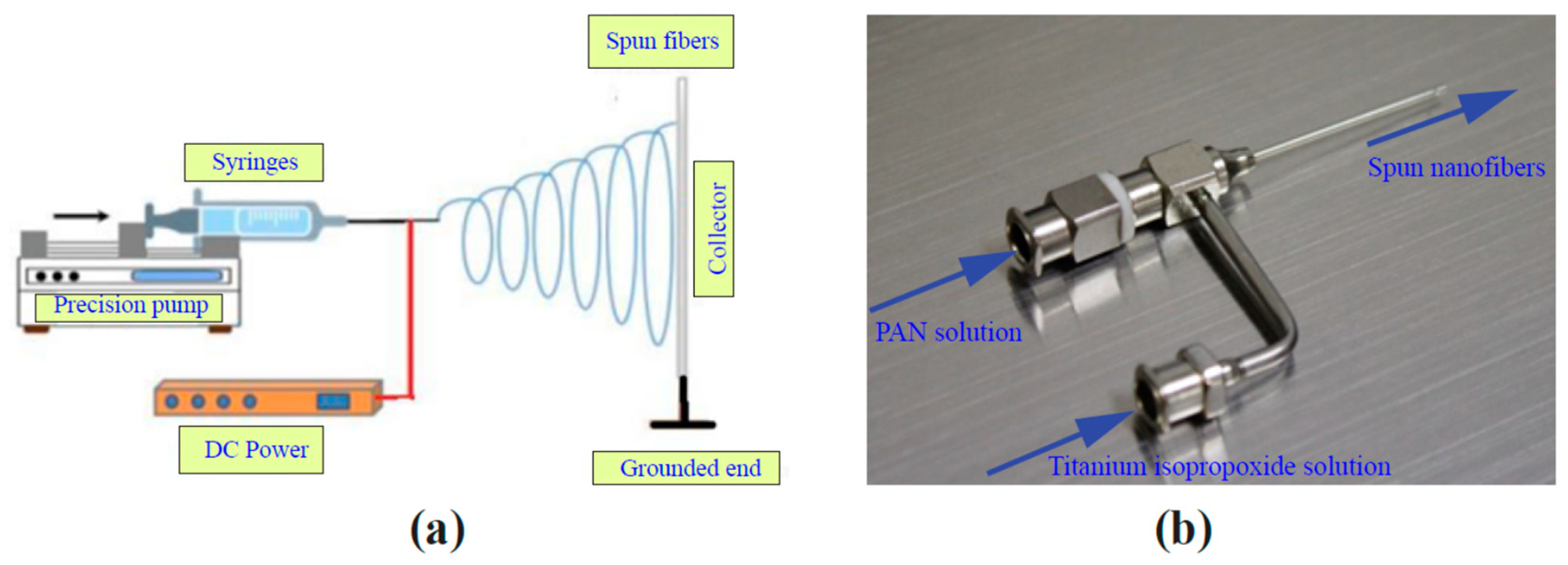
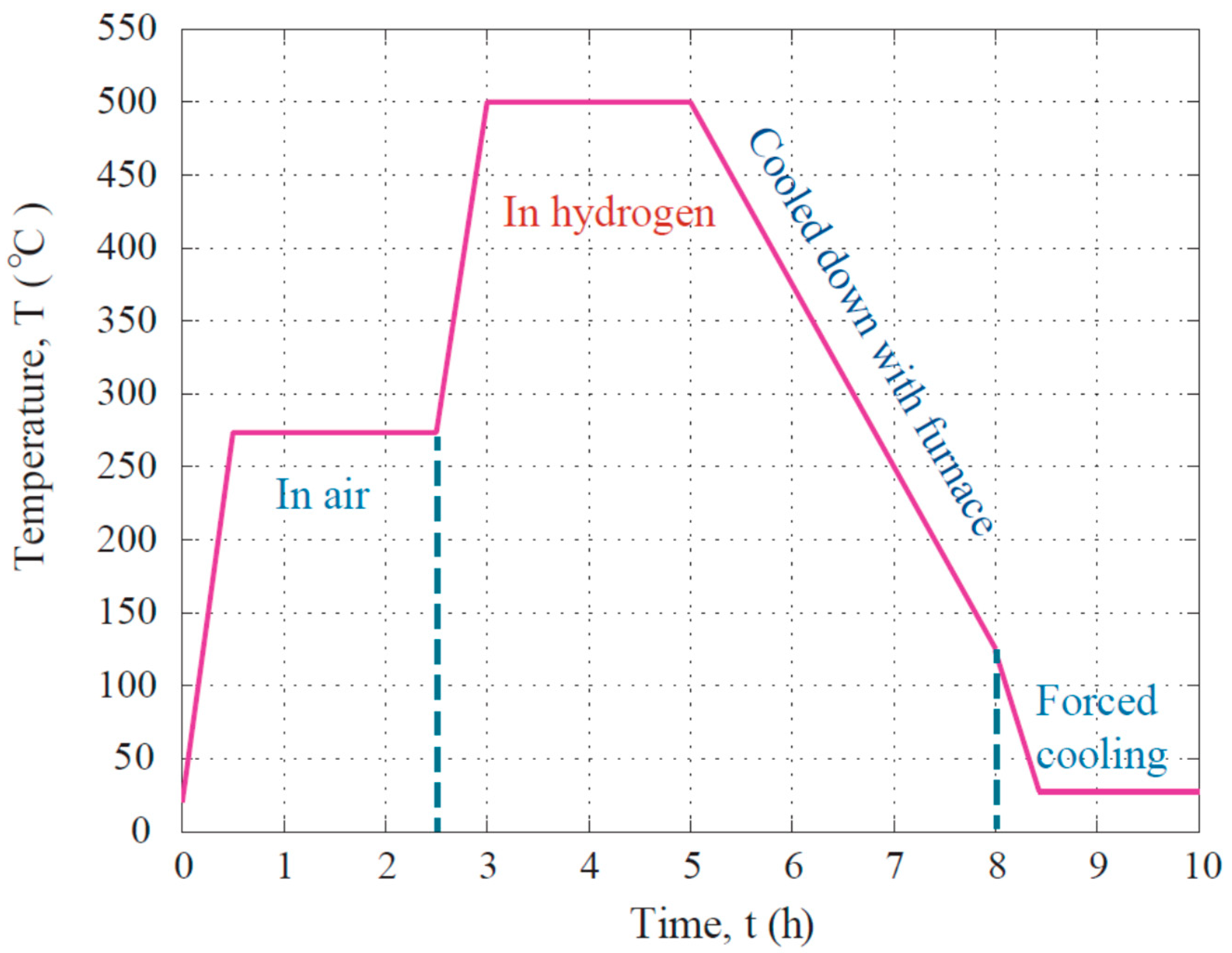
2. Materials and Methods

Polyacrylonitrile (PAN) with an approximate molecular weight of 150,000 was supplied by Scientific Polymer Products, Inc., Ontario, NY, USA. Dimethylformamide (DMF) was purchased from Alfa Aesar, Ward Hills, MA, USA. Titanium (IV) isopropoxide (95%) was also purchased from Alfa Aesar. A high voltage direct current power source was supplied by Spellman, Inc., Hauppauge, NY, USA. A Fusion 200 precision syringe pump was purchased from Chemyx, Inc., Stafford, TX, USA. An OTF-1200X compact split tube furnace made by MTI Corporation, Richmond, CA, USA was used for heat treating the prepared materials.
Electrohydrodynamic casting or electrospinning was the process used to fabricate the fibers in the experiment. This method has the advantage of easy deposition and is versatile for the manufacturing of polymeric materials, composites, and ceramics [13]. This process provides sufficient electrostatic force by applying a very large DC voltage difference between the solution and collector to overcome and surface tension of the PAN and titanium isopropoxide solutions, which made the titanium oxide particle-forming solution and the PAN solution co-spun or co-cast onto the collector, and formed a composite microfiber in the reaction spinning process. Figure 1a shows the layout of the equipment and Figure 1b illustrates the spinneret for the fiber processing.
The following forms of materials were used to make the solutions for this process. Polyacrylonitrile polymer (PAN) was supplied in powder form. Dimethylformamide (DMF) was used as the solvent for PAN. Titanium oxide (TiO2) (Cal Poly Pomona, Pomona, CA, USA) was made in nanoscale powder from the hydrolysis of titanium metal-organic compound. Acetic acid (CH3 COOH) (Alfa Aesar, Ward Hill, MA, USA) was used as the stable agent. The first step was to prepare the titanium oxide powder mixed into acetic acid with no critical percentage ratio because the solution would absorb water from ambient air. Roughly 10 mL of ethanol was used to dissolve about 1.0 g of titanium isopropoxide. Then, several drops of acetic acid were added into the solution as the stabilizer. The dissolving process took 4 h in a test tube mixer to ensure the solution quality. The next step was to prepare the PAN solution, with a 1 to 9 ratio; 1.0 g of polyacrylonitrile polymer per 9 mL of dimethylformamide solvent to obtain the concentration of 10% PAN solution. This mixing process was done in the test tube mixer.
With the completion of preparing two solutions, the PAN and titanium isopropoxide solutions were filled into two separated syringes. These two 15 mL syringes were connected with a coaxial spinneret. The PAN-DMF core fluid was pumped by a Chemxy precision syringe pump and the syringe was connected to the 20-gauge inner needle. The syringe that contained titanium isopropoxide solution was attached to a flexible PVC tube and a 16-gauge spinneret. Both needles were bonded together to form a coaxial spinneret setup, which is shown in Figure 1b. Since the titanium isopropoxide solution formed the outer-layer flow, it reacted with water in the air to produce titanium hydroxide. This setup provided a structure where the titanium isopropoxide would generate a titanium hydroxide-containing shell layer on the PAN-DMF jet.
When the fiber was finally produced, it was necessary to go to the second step—i.e., the heat treatment step of the experiment. Before putting these two syringes into the programmable precision syringe pump, the air was purged from both of the syringes to ensure the consistency of flow rate of solution. A distance of 15 cm was kept between the tip of the needles and the fiber collector plate. A DC power supply was linked in between the tip of the coaxial spinneret and the final collector plate. This power supply was connected to a high voltage AC-DC converter, which had its positive lead on the spinneret, and negative lead on the collector plate. This setup facilitated the electrospinning process under room temperature and generic atmospheric conditions. The injection speeds of both syringes were adjusted between 0.001 to 0.01 mL/min depending on the collecting condition. A DC voltage of 15 kV was applied to electrify the solutions, and this potential difference led the charged jet to cast fibers on the collector plate. The resultant microfiber was sprayed and collected on a tissue paper which was placed on the stainless-steel collector plate, which gave the advantage of separating the fabricated fiber easier than itself. The entire electrospinning and collecting process took approximately 2 h so that the fiber mat could have the desired thickness and strength for the later heat treatment process. It was measured that the collected fiber mat samples after electrospinning reached a thickness of 400 µm. The fiber has an average diameter in the micron meter range. The yield of the electrospinning process is about 90%.
Heat treatment of the fabricated microfiber caused oxidation of PAN and complete dehydration of titanium hydroxide by setting the specimen into a quartz tube furnace at 250 °C for 2 h. The air in the quartz furnace was replaced with hydrogen after the heating temperature was raised to 500 °C and the heating process continued for an additional 2 h before cool down. At this high temperature in hydrogen, the PAN fiber was converted into a partially carbonized state. Also, the titanium hydroxide was completely converted into dioxide. During the cooling process, the specimen remained in its position inside the furnace tube; this process could take different amounts of time due to different ambient temperature. Figure 2 represents the complete time-temperature profile associated with the heat treatment process. After the heat treatment, the average diameter of the fiber was reduced significantly.
The photovoltaic tests were performed on the titanium dioxide coated carbon fiber composite. A fluorescent light tube was used to generate visible light. A CHI440C Electrochemical Workstation, made by CH Instrument, Austin, TX, USA was used to record the voltage response data. The sample fiber was set on transparent glass slides and aluminum foil strips were used as the electrical conducting path. The light source was controlled as 25 s ON followed by 25 s OFF. The test results were obtained by plotting the open circuit potential versus time.

3. Results and Discussion

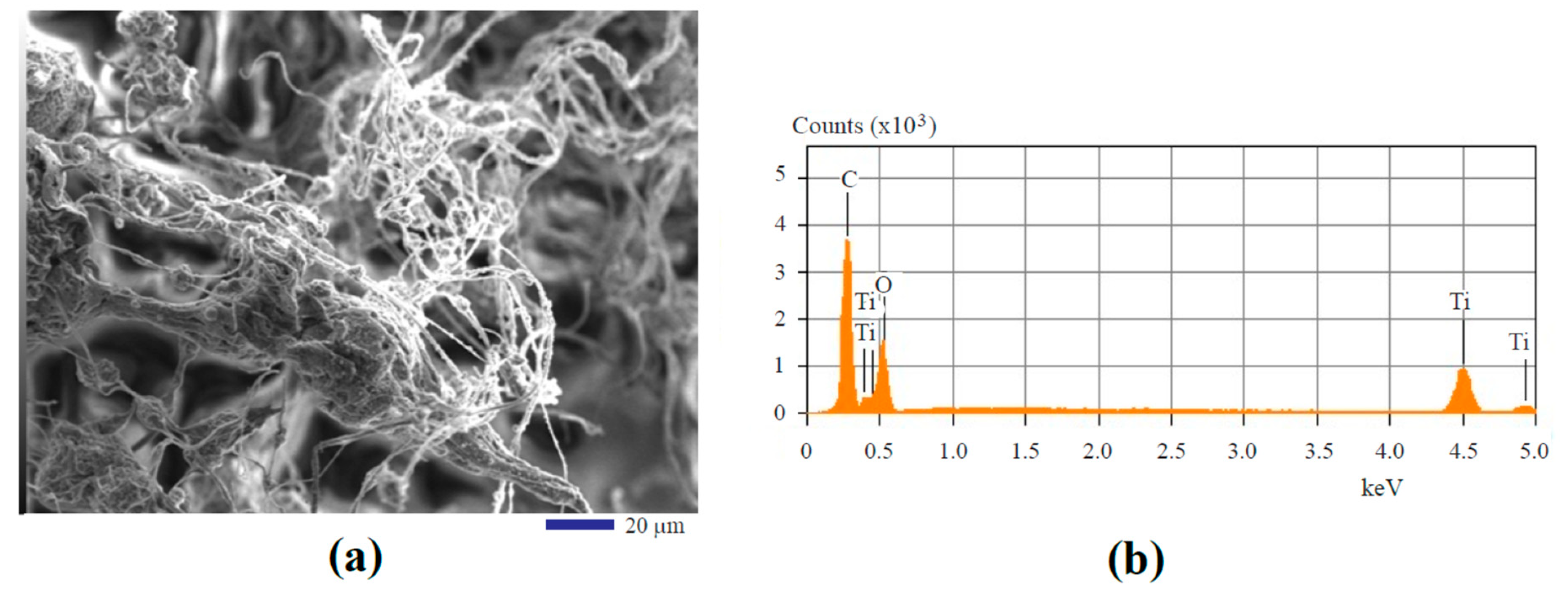
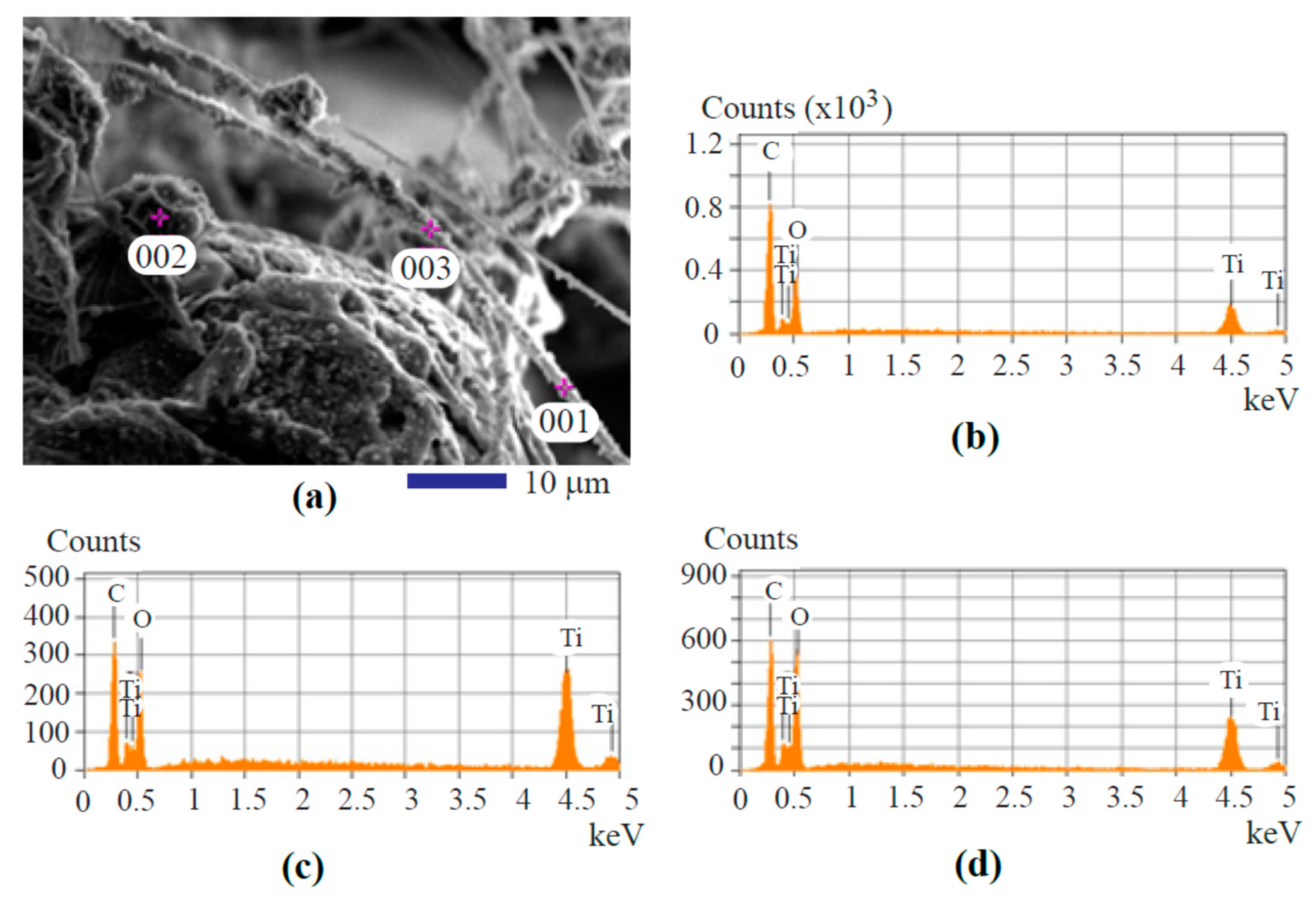
3.1. Morphology and Composition

The scanning electron microscopy (SEM) was used to observe the microstructure and determine the composition of the specimen. Photoelectric energy conversion properties of the partially carbonized nanofiber were characterized using an electrochemical workstation. Earlier work on microstructure analysis showed that electrospun fibers were randomly oriented in different layers [14]. Figure 3a shows the microstructure of the particle coated composite carbon fiber specimen under SEM. The diameter of the fibers can be adjusted by varying the rheological properties of the solution and tuning the processing parameters as reported [15]. At a slightly higher magnification, the SEM micrograph of Figure 3b revealed that the titanium dioxide nanoparticles were laying on the partially carbonized PAN fiber. The sizes of these titanium dioxide particles varied from several tens to several hundreds of nanometers. During the second stage of the heat treatment at 500 °C, a size reduction of the nanofiber occurred due to the evaporation of smaller molecules in the PAN polymer. The PAN fiber coated with titanium oxide had an average diameter of 4 µm. After the heat treatment, the fiber had an average diameter of 2 µm. The initial size and the heat-treated fiber size were determined by microscopic examination, and the results were obtained using the quantitative measurement on the dimension of the fiber filaments shown in typical SEM images.
It is meaningful to reveal the composition profile of the microfiber. A typical area of the fiber mat as shown in the SEM image of Figure 4a was chosen for X-ray diffraction energy dispersive spectroscopic analysis. Only Ti, O, and C signals were observed on the X-ray diffraction energy dispersive spectrum as shown in Figure 4b. As mentioned, the results shown in Figure 4b were obtained by the area mapping analysis and the mapping region as defined by the whole area of Figure 4a. Since Figure 4b only provides qualitative information, quantitative results from the elemental analysis are listed as a part in Table 1.
It must be indicated that at temperatures higher than 450 °C, the crystallization of TiO2 particles converts the rutile form to anatase [16]. Therefore, the obtained TiO2 nanoparticles in this work should be in the anatase form with high photosensitivity. In the SEM analysis, since the titanium element has a higher atomic mass than any other elements in PAN, it generates stronger backscattering electron signals. Therefore, the regions containing titanium dioxide showed the highest brightness in the micrograph. The partially carbonized fibers formed the grey tone due to the relatively low atomic mass of carbon. It must be noted that the heat treatment could result in the morphology changing of the composite fiber as also indicated in [17].
Energy Dispersive Spectrum (EDS) of X-ray diffraction spot analysis was used to identify the elemental composition of the selected locations. In the SEM image as shown by Figure 5a, three different locations were picked to perform the spot analysis for comparison. The results from the spot analysis are shown in Figure 5b–d. The top detected elements are Ti, O, and C, which matches the chemical compositions of the fabricated particle-containing composite nanofiber. No nitrogen element was detected through this process indicated the experiment was successful in view of converting the PAN polymer into a carbonized fiber.
Figure 5b–d shows the spot EDS analysis results obtained from the analysis of specific locations of Spots 001, 002, and 003, as indicated in the SEM image of Figure 5a. The results from Figure 5b–d can be summarized in the lower part of Table 1. Although the elements found from these locations are identical, there exist differences in the quantities. Such differences reveal whether a location is a particle or a carbon fiber. For example, Spot 002 is a particle cluster area, the titanium concentration is higher than in other locations.
In order to show the statistical results of the elemental analysis, more spot composition analyses of the fiber filaments and the oxide clusters were performed. More than 15 locations containing each microstructural feature (fiber or nanoparticle cluster) were examined. The X-ray diffraction energy spectrum data revealed the following statistical results. The mean and the standard deviation of the spot analysis results are listed in Table 2 and Table 3, respectively. From the data in Table 2, we can see that the fiber coated with titanium dioxide nanoparticle coating has much higher carbon content than the oxide cluster. The EDS elemental analysis data showed relatively high standard deviations for all the elements as listed in Table 3. One of the reasons for such behavior may be due to the limited point resolution of the X-ray diffraction instrument in submicron scale when a significant change in the depth of the locations for analysis exists. The other reason is the inhomogeneity of the material in view of both structure and composition. The complexity and the inhomogeneity of the composite fiber come from the reaction spinning process. During the coaxial electrospinning, the titanium organic compound was actively involved in moisture absorption to form titanium hydroxide. Since the hydrolysis is a multiphase reaction, the water moisture content is not constant in the space due to the whipping motion of the fiber. Therefore, the titanium hydroxide nanophase nucleation and growth were not so easy to control. This caused the uneven distribution of the titanium dioxide nanoparticles on or underneath the carbonized fiber surface. The carbonized fiber surface as shown in Figure 3a,b, Figure 4a, and Figure 5a contains knots and clusters of oxide, which is due to this rapid but not so easy to control reaction during the spinning.
It must be noted that the nanoparticle cluster shows higher titanium and oxygen concentrations as revealed by the data in Table 2. This should not be considered as an advantage because the uniform doping of carbon in the titanium dioxide will be hard to realize. Such a disadvantage may be alleviated by controlling the relative humidity of the fiber spinning environment. By reducing the humidity, the hydrolysis reaction will slow down, which allows the PAN polymer to mix with the titanium hydroxide more sufficiently in the nanofiber. The electrospinning in a non-ambient humidity environment may be helpful to better understand the titanium oxide nanoparticle growth kinetics within the carbon fiber, which is one of our future study topics.

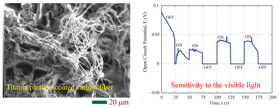
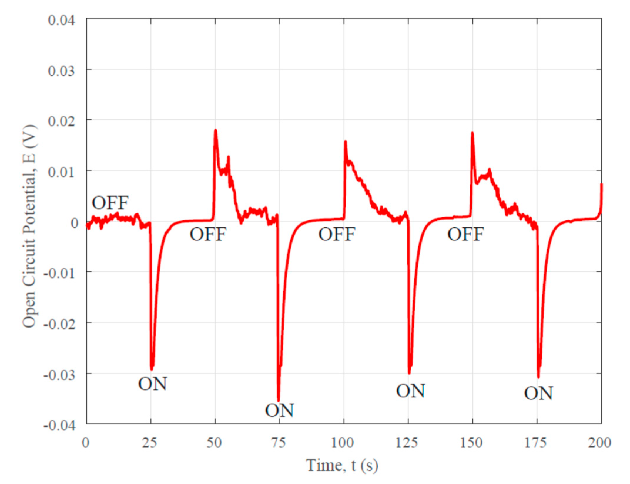
3.2. Photovoltaic Property

The photovoltaic response of the processed oxide coated carbon fiber composite is demonstrated in Figure 6. A 120 W fluorescent light was used to generate the time-dependent voltage in this work. The voltage responses were recorded using an electrochemical workstation, CHI440C, made by CH Instrument, Austin, TX, USA. When the sample fiber was exposed under the fluorescent lamp which was placed 1.5 m away from it, positive charging was found. There were 4 total cycles recorded and the peak value voltage of 0.04 V was observed. From the figure, we can see that every cycle includes 25 s ON followed by 25 s OFF. The test revealed an identical behavior of generating electricity under photon energy excitation. In addition, positively charged holes allow for the measured voltage to spike into a more positive region. This concludes that the titanium oxide containing nanofiber has a typical p-type semiconductor behavior as also reported in [18]. The fast response as seen from Figure 6 also indicated the high photocatalytic activity of the fiber composite.
It must be noted that the carbon nanofiber made from PAN without the TiO2 nanoparticle coating has a different photovoltaic response as shown in Figure 7. As can be seen from Figure 7, at the beginning of the photovoltaic test, the light source was OFF, the open circuit potential was almost zero, i.e., the system in an equilibrium state. When the light was ON, the open circuit potential changed rapidly to the negative values. This is due to the electron generation at the working electrode induced by the photonic energy excitation. It was also found that the recombination of the electron-hole charge pairs was quite quick because the open circuit potential decayed quickly as time elapsed.
There are two possible reasons for the high photovoltaic sensitivity of the TiO2 coated carbon fibers to the visible light. One reason is due to the carbon doping in the TiO2. This changes the energy bandwidth of the oxide. Pure titanium oxide is only sensitive to UV light, but the carbon doping can narrow the band gap of the oxide. This is the major reason for the visible light sensitivity. Another reason is from the conjugated structure of the carbonized fiber, which causes the localization of the charges. Such a localization allows the carbon fiber to show unique semiconducting behavior. Tuning the band gap of the carbon fiber is possible by controlling the intercalation state in the carbon fiber and tailoring the conductivity of the material. A higher Ti composition could improve the intensity of the photovoltaic response because of stronger light absorption. However, too much titanium oxide in the composite fiber could damage the band gap for the visible light absorption. Because titanium oxide is intrinsically an ultraviolet (UV) light absorber. The sporadic and uniform distribution of the titanium oxide nanoparticles at the surface and in the composite can significantly enhance visible light absorption, as revealed by the results in Figure 6. This fast photoelectric response property is important for potential applications on flexible photovoltaic solar panels and/or photon sensing detectors for monitoring traffic flow in the night time.

4. Conclusions

Electrospinning, the processing method of the TiO2-PAN microfiber, has delivered the desired functional composite fiber material successfully. Subsequent heat treatment carbonized the PAN fiber and generated anatase titanium dioxide nanocrystal particles on the fiber. The special structure and composition ensured the photovoltaic responses of this fiber. The elemental composition analysis confirmed all the elements in the resultant fiber; no contamination had occurred during the entire casting process. SEM observation shows the distribution of the titanium dioxide particles on the partially carbonized microfibers. The morphology of the composite material reveals the random orientation of the fibers. Photovoltaic responses show the p-type semiconducting behavior of the heat-treated composite material. It is highly sensitive to visible light. The fabricated microfiber shows fast photoelectric responses. Therefore, partially carbonized TiO2 coated carbon fiber has the potential to be used for photoelectric energy conversion and photonic sensing.

Author Contributions

Conceptualization, Y.X.G.; Data curation, J.B.G.; Formal analysis, Y.X.G.; Funding acquisition, Y.X.G.; Investigation, L.Y., X.W., J.P.M., C.Y., N.P., J.B.G., Y.Z. and Y.X.G.; Methodology, Y.X.G.; Project administration, Y.X.G.; Resources, Y.X.G.; Supervision, Y.X.G.; Writing – original draft, Leonardo Yuan.

Funding

This work was supported in part by the National Science Foundation (NSF) under Grant Number CMMI-1333044. The SEM images were made possible through the NSF MRI grant DMR-1429674. The two summer undergraduate researchers, N.P. and C.Y., were supported by the Citrus College Race to STEM Program co-managed by Marianne Smith and Winny Dong. We also acknowledge the support by the California State University Pomona 2016–2017, 2017–2018, and 2018–2019 Provost’s Teacher-Scholar program, the 2016–2017 SPICE grant program, and the 2018–2019 RSCA grant program.

Acknowledgments

Anan Hamdan is appreciated for his assistance in the SEM experiment.

Conflicts of Interest

There is no conflict of interest regarding the publication of this paper.

References

  1. Huang, Z.M.; Zhang, Y.Z.; Kotaki, M.; Ramakrishna, S. A review on polymer nanofibers by electrospinning and their applications in nanocomposites. Composites Sci. Tech. 2003, 63, 2223–2253. [Google Scholar] [CrossRef]
  2. Park, J.Y.; Lee, I.H. Characterization and Morphology of Prepared Titanium Dioxide Nanofibers by Electrospinning. J. Nanosci. Nanotech. 2010, 10, 3402–3405. [Google Scholar] [CrossRef]
  3. Caratao, B.; Carneiro, E.; Sa, P.; Almeida, B.; Carvalho, S. Properties of electrospun TiO2 nanofibers. J. Nanotech. 2014, 2014. [Google Scholar] [CrossRef]
  4. Zhao, L.R.; Jang, B.Z.; Zhou, J.L. Effect of polymeric precursors on properties of semiconducting carbon/carbon composites. J. Mater. Sci. 1998, 33, 1809–1817. [Google Scholar] [CrossRef]
  5. Gan, Y.X.; Draper, C.W.; Gan, J.B. Carbon nanofiber network made by electrohydrodynamic casting immiscible fluids. Mater. Today Comm. 2017, 13, 248–254. [Google Scholar] [CrossRef]
  6. Gan, Y.X.; Chen, A.D.; Gan, J.B.; Anderson, K.R. Electrohydrodynamic casting bismuth telluride micro particle loaded carbon nanofiber composite material with multiple sensing functions. J. Micro Nano-Manuf. 2018, 6. [Google Scholar] [CrossRef]
  7. Gan, Y.X.; Chen, A.D.; Gan, R.N.; Hamdan, A.S. Energy conversion behaviors of antimony telluride particle loaded partially carbonized nanofiber composite mat manufactured by electrohydrodynamic casting. Microelectron. Eng. 2017, 181, 16–21. [Google Scholar] [CrossRef]
  8. Gan, Y.X. A review of electrohydrodynamic casting polymer composites for energy conversions. AIMS Mater. Sci. 2018, 5, 206–225. [Google Scholar] [CrossRef]
  9. Nakata, K.; Fujishima, A. TiO2 photocatalysis: Design and applications. J. Photochem. Photobiol. C Photochem. Rev. 2012, 13, 169–189. [Google Scholar] [CrossRef]
  10. Tang, Z.; Bolong, N.; Saad, I. Response surface modeling of electrospinning parameters on titanium oxide nanofibers diameter: A Box-Behnken Design (BBD). Adv. Sci. Lett. 2017, 23, 11237–11241. [Google Scholar] [CrossRef]
  11. Singh, E.; Nalwa, H.S. Graphene-based dye-sensitized solar cells: A review. Sci. Adv. Mater. 2015, 7, 1863–1912. [Google Scholar] [CrossRef]
  12. Uddin, M.J.; Dickens, T.; Yan, J.; Chirayath, R.; Olawale, D.O.; Okoli, O.I. Solid state dye-sensitized photovoltaic micro-wires (DSPMs) with carbon nanotubes yarns as counter electrode: Synthesis and characterization. Solar Energy Mater. Solar Cells 2013, 108, 65–69. [Google Scholar] [CrossRef]
  13. Chronakis, I.S. Novel nanocomposites and nanoceramics based on polymer nanofibers using electrospinning process—A review. J. Mater. Proc. Tech. 2005, 167, 283–293. [Google Scholar] [CrossRef]
  14. Jalili, R.; Morshed, M.; Ravandi, S.A.H. Fundamental parameters affecting electrospinning of PAN nanofibers as uniaxially aligned fibers. J. Appl. Polym. Sci. 2006, 101, 4350–4357. [Google Scholar] [CrossRef]
  15. Watthanaarun, J.; Pavarajarn, V.; Supaphol, P. Titanium (IV) oxide nanofibers by combined sol-gel and electrospinning techniques: Preliminary report on effects of preparation conditions and secondary metal dopant. Sci. Tech. Adv. Mater. 2005, 6, 240–245. [Google Scholar] [CrossRef]
  16. Nuansing, W.; Ninmuang, S.; Jarenboon, W.; Maensiri, S.; Seraphin, S. Structural characterization and morphology of electrospun TiO2 nanofibers. Mater. Sci. Eng. B 2006, 131, 147–155. [Google Scholar] [CrossRef]
  17. Wijanarko, T.A.W.; Kusumaatmaja, A.; Roto, C.; Triyana, K. Effect of heat treatment on morphology and crystallinity of electrospun polyvinyl alcohol nanofibers. AIP Conf. Proc. 2016, 1755. [Google Scholar] [CrossRef]
  18. Kim, J.; Lee, J.Y.; Lim, J.H.; Myung, N.V. Optimization of thermoelectric properties of p-type AgSbTe2 thin films via electrochemical synthesis. Electrochim. Acta 2016, 196, 579–586. [Google Scholar] [CrossRef]
Figure 1. Equipment layout of the reaction spinning process: (a) schematic of the reaction spinning; (b) photograph of the co-axial spinneret for the reaction spinning.
Fibers 07 00049 g001
Figure 2. Time-temperature profile associated with the heat treatment on the spun fibers.
Fibers 07 00049 g002
Figure 3. Scanning electron microscopic (SEM) analysis of the reaction spun composite fibers: (a) a lower magnification image showing the microfiber on the substrate; (b) a higher magnification image showing the titanium dioxide nanoparticles located at the surface of the carbon fibers.
Fibers 07 00049 g003
Figure 4. Energy dispersive spectroscopic analysis of the microfiber specimen: (a) a Scanning Electron Microscope (SEM) image showing the selected area for mapping; (b) spectrum from the area mapping.
Fibers 07 00049 g004
Figure 5. The specific location selections for the spot analysis and the element analysis results: (a) SEM image showing the locations for Energy Dispersive Spectrum (EDS) spot analysis; (b) the energy dispersive spectrum of location 001; (c) the energy dispersive spectrum of location 002; (d) the energy dispersive spectrum of location 003.
Fibers 07 00049 g005
Figure 6. Photovoltaic response of the partially carbonized fiber coated with the titanium oxide nanoparticle coating to visible light showing the p-type semiconducting behavior.
Fibers 07 00049 g006
Figure 7. Photovoltaic response of the partially carbonized fiber made from Polyacrylonitrile (PAN) to the visible light showing the n-type semiconducting behavior.
Fibers 07 00049 g007
Table 1. Atomic mass content from area mapping and spot analysis.
Type of EDSLocations for AnalysisCarbonOxygenTitanium
area mappingthe entire region in Figure 4a54.59%28.40%17.01%
spot analysisspot 001 shown in Figure 5a54.43%30.91%14.66%
spot analysisspot 001 shown in Figure 5a34.57%33.97%31.47%
spot analysisspot 001 shown in Figure 5a37.82%42.42%19.77%
Table 2. Composition analysis statistical results showing the mean of atomic mass content from the energy dispersive X-ray diffraction spot analysis of 15 samples.
Locations for AnalysisCarbonOxygenTitanium
coated fibers49.42%34.23%16.21%
oxide clusters38.11%37.86%23.98%
Table 3. Composition analysis statistical results showing the standard deviation of atomic mass content from the energy dispersive X-ray diffraction spot analysis of 15 samples.
Locations for AnalysisCarbonOxygenTitanium
coated fibers9.07%7.75%6.24%
oxide clusters8.55%7.08%8.35%

