Article

In-Line Nanostructuring of Glass Fibres Using Different Carbon Allotropes for Structural Health Monitoring Application

1
Leibniz-Institut für Polymerforschung Dresden e.V., Hohe Str. 6, D-01069 Dresden, Germany
2
Institut für Leichtbau und Kunststofftechnik, Technische Universität Dresden, D-01062 Dresden, Germany
3
Institut für Textilmaschinen und Textile Hochleistungswerkstofftechnik, Technische Universität Dresden, 01069 Dresden, Germany
*
Author to whom correspondence should be addressed.
Submission received: 16 April 2019 / Revised: 28 June 2019 / Accepted: 1 July 2019 / Published: 10 July 2019
(This article belongs to the Special Issue Advances in Glass Fibers)

Abstract

:
By the in-line nanostructuring of glass fibres (GF) during the glass fibre melt spinning process, the authors achieve an electro-mechanical-response-sensor. The glass fibre interphase was functionalized with different highly electrically conductive carbon allotropes such as carbon nanotubes, graphene nanoplatelets, or conductive carbon black. On-line structural health monitoring is demonstrated in continuous glass fibre-reinforced polypropylene composites during a static or dynamic three-point bending test. The different carbon fillers exhibit qualitative differences in their signal quality and sensitivity due to the differences in the aspect ratio of the nanoparticles, the film homogeneity, and the associated electrically conductive network density in the interphase. The occurrence of irreversible signal changes during dynamic loading may be attributed to filler reorientation processes caused by polymer creeping or to the destruction of the electrically conductive paths due to the presence of cracks in the glass fibre interphase. Further, the authors found that sensor embedding hardly influences the tensile properties of continuous GF reinforced polypropylene (PP) composite.

1. Introduction

Glass fibre (GF)-reinforced thermoplastics are used for lightweight constructions due to their excellent characteristics in terms of stiffness, strength and design flexibility. To replace the commonly used metals, the long-term stability of lightweight constructions has to be ensured. Therefore, detailed information on the inner bulk phase and the GF-matrix interphase is required in order to obtain basic knowledge about the failure pattern of GF-reinforced thermoplastics. The integration of structural health sensors is required to obtain information from the inner bulk. However, the reinforcing fibres were mostly substituted by sensor fibres; e.g., carbon, carbon nanotube (CNT) yarns, piezo-resistive ceramics, or Bragg gratings [1,2,3,4,5,6,7,8,9,10]. Another approach of localizing material damage is the use of printed conductive paths [11,12] or CNT-filled coatings [13] which are deposited on the top of a composite. Furthermore, due to the incorporated piezoresistive effect by filling the whole polymer matrix with electrically conductive fillers such as CNT [14], carbon nano fibres (CNF) [15,16], and graphene nanoplatelets (GNP) [17,18], an analysis of mechanical stresses in parts is also possible.
Unfortunately, no information on the most critical interfacial region [19,20,21,22] for the stress transfer between GF and the surrounding matrix, e.g., polypropylene (PP), is accessible with the above-described sensor systems. To detect the mechanical stress level in the GF thermoplastic interphase, an embedded electrically conductive network enables the detection of mechanical stress–strain behaviour. Due to the implemented piezoresistive effect, it is possible to correlate the occurring mechanical deformation with the monitored electrically conductive change [23,24,25,26,27,28,29,30]. The use of carbon nanotubes (CNT) for the nanostructuring of GF results in sensor fibres which are suitable for measuring the interphase deformation in a quantitative manner [27,31,32,33,34,35]. Furthermore, early stage damage can be predicted by on-line resistance measurements, since the GF interphase fails prior to ultimate structural failure. Also, other electrically conductive carbon fillers such as carbon black (CB) and graphite nanoplatelets (GNP) show the suitable implementability of structural health monitoring in the interphase [23]. Respectively, due to the different nanoparticle shapes (1D to 3D [21]), such as fibre-like and sheet-like as well as spherical-like shapes, qualitative differences in the signal quality and sensitivity are obtained. For market entrance, a reproducible in-line nanostructuring of glass fibre surfaces with a higher productivity level is necessary. Therefore, the results of the preliminary work on off-line nanostructuring [23] have to be transferred to an in-situ sizing process during continuous fibre melt spinning.
In this study, the authors investigated the possibility of up-scaling glass fibre nanostructuring manufacture for the industrial-scale preparation of composites with embedded interface sensing abilities. Therefore, the equipment had to be changed from a secondary fibre coating device [23,27,28] with a low velocity (0.1–16 m∙min−1) to a glass fibre melt spinning device using a high spinning velocity (100–550 m∙min−1). Consequently, the authors investigated the influence of the filler morphology of CNT, CB, GNP and the spinning velocity on the glass fibre nanostructuring process to finally prepare a sensor fibre with suitable electro-mechanical-response behaviour for structural health monitoring applications in GF/PP composites.

2. Experimental

2.1. Materials and Processing

2.1.1. Glass Fibre Spinning and Interface Modification

Two different types of yarns were produced by melt spinning. At first, a commingled hybrid yarn [36,37], 50/50 vol.% consisting of continuous E-glass filaments (average diameter of 17 µm) and PP filaments (average diameter of 22 µm, PP: HG455FB, Borealis, Austria) were simultaneously spun and sized using an aqueous 3-aminopropyltriethoxysilane (Dynasylan® AMEO, Evonik, Essen, Germany, 1 wt.%) and maleic anhydride grafted PP film former (10 wt.%, Aquacer 598, Byk, Wesel, Germany) solution. Further, E-glass fibres were melt-spun, which were in-line nanostructured with different electrically conductive carbon fillers (Table 1), using a fibre sizing solution containing an aqueous 3-aminopropyltriethoxysilane (Dynasylan® AMEO, Evonik, Essen, Germany, 1 wt.%) and maleic anhydride grafted PP film former (5–20 wt.%, Aquacer 598, Byk, Wesel, Germany) solution. The chosen filler content of the sizing amounted to 5 wt.% for CNT (Nanocyl™ NC7000, Sambreville, Belgium) and GNP (Graphit Kropfmühl, EXG 98 300, Hauzenberg, Germany) as well as 10 wt.% CB (Printex XE2B, Orion Engineered Carbons, Senningerberg, Luxembourg), relative to the solid content of the film former.

2.1.2. Preparation of the Nanostructured Fibre Sizing

The different carbon fillers were dispersed into a PP film former solution (Aquacer 598, Byk, Wesel, Germany) by an ultrasonic treatment process using a continuous flow cell (Hielscher UP200S + D14K, Teltow, Germany). The sonication cell was water-chilled to dissipate the heat produced during the ultrasonic treatment. To compare the influence of the different filler morphologies on the electromechanical response behaviour of nanostructured GFs, an equivalent state of dispersion is required. Based on recent systematic studies [23], all fibre sizings were prepared with an ultrasonic treatment of 60 min.

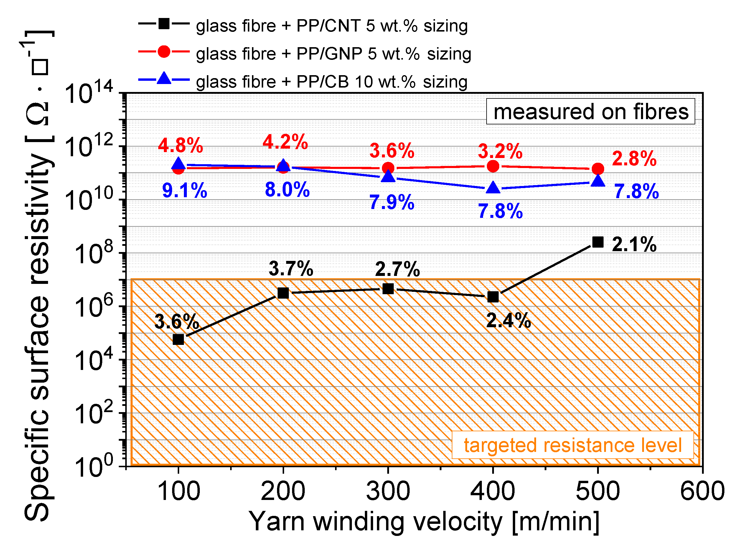
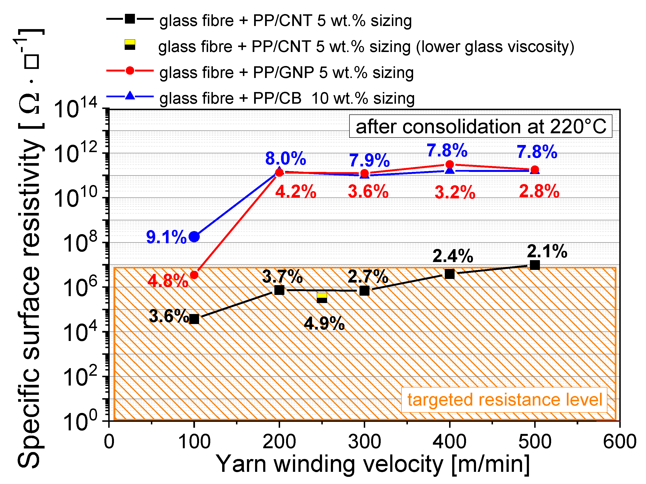
2.1.3. Electrical Characterization

Electrical resistivity measurements of the fibre bundles were carried out in accordance with ASTM-D257 [43] using a Keithley 8002A test fixture for 60 mm-long fibres combined with a Keithley electrometer 6517A for fibre resistances >108 Ω or a Keithley DMM 2001 multimeter for fibre resistances < 108 Ω. At least 3 fibres were measured to obtain the arithmetic mean value and the corresponding standard deviation of resistivity.

2.1.4. Mechanical Characterization

The 3-point bending tests (DIN ISO 14125 [44]) were performed using a universal test machine (All-round Line, Zwick Roell, Ulm, Germany). The tensile properties of the continuous unidirectional reinforced fibre composites were determined in accordance with ISO 527 [45], using 10 samples. Longitudinal tensile properties were measured on specimen type A, with the dimensions 190 mm × 15 mm × 1 mm using the Retro Line TIRA Test 2300 machine, and the transversal measurements tensile properties were measured on specimen type B, with the dimensions 180 mm × 25 mm × 2 mm using Zwick/Roell (Ulm, Germany) 1456. Both ends of the tensile test samples were equipped with supporting end tabs using a 3M DP 8010 acrylate adhesive (curing under pressure, for 24 h). The length between the end tabs amounted to 130 mm and 80–85 mm for longitudinal and transversal measurements, respectively. All strain values of the longitudinal measurements were determined at a crosshead corrected by the stiffness of the machine. The measuring velocity was set to 2 mm/min. For the transversal measurements, the velocity amounted to 1 mm/min.

2.1.5. GF-Composite Preparation

The preparation of the unidirectional GF composites for the electro-mechanical-response behaviour testing was conducted by a yarn winding process (in accordance to ISO 9291 [46]). As shown in Figure 1 (left), the nanostructured GF yarns were placed on a steel mandrel frame, with and without a noticeable conductive silver paint. Subsequently, several layers of non-conductive hybrid yarns were wound onto the frame, in the direction of the carbon filler-coated yarns (Figure 1, right).
The hybrid yarn was consolidated by compression molding (K207, Rucks GmbH, Glauchau, Germany) at 225 °C. The fibre consolidation procedure is shown in Figure 2. The wound fibres were heated in a rectangular pre-form; after heating to 225 °C (10 K/min), the temperature was kept constant for 21 min at a pressure of 10 bar to ensure a full yarn melt down. The void-free consolidation was experimentally investigated in a previous study [47]; by choosing a suitable combination of temperature and time, the mechanical composite properties were enhanced.
Subsequently, the pressure was increased to the value at which the glass fibres were fully wetted (45 bar, 2 min), followed by cooling down (rate 70 K/min) to room temperature. The test specimens were prepared using a diamond circular saw. All specimens were conducted with electrical cables using silver adhesive in order to facilitate electrical measurements.

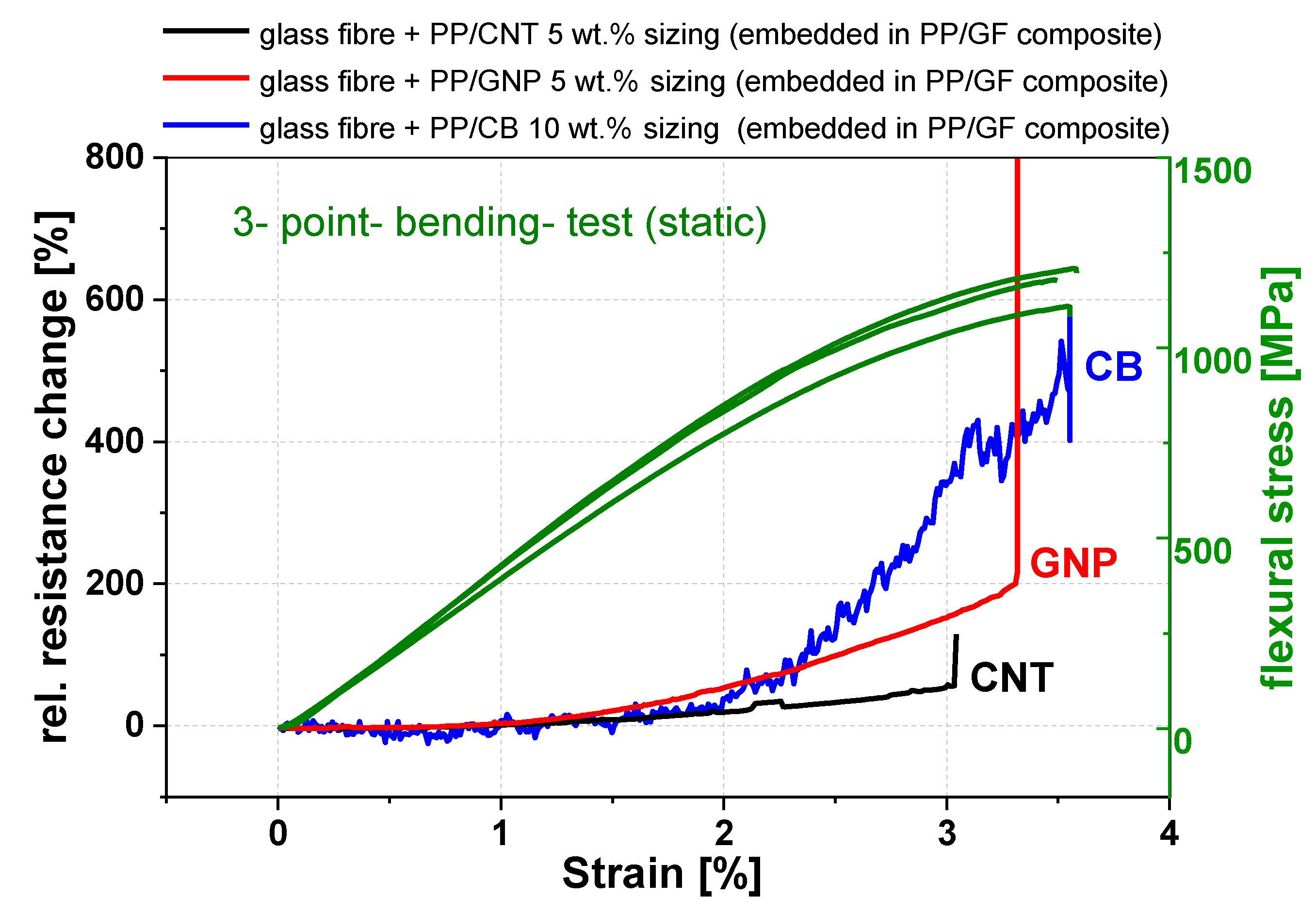
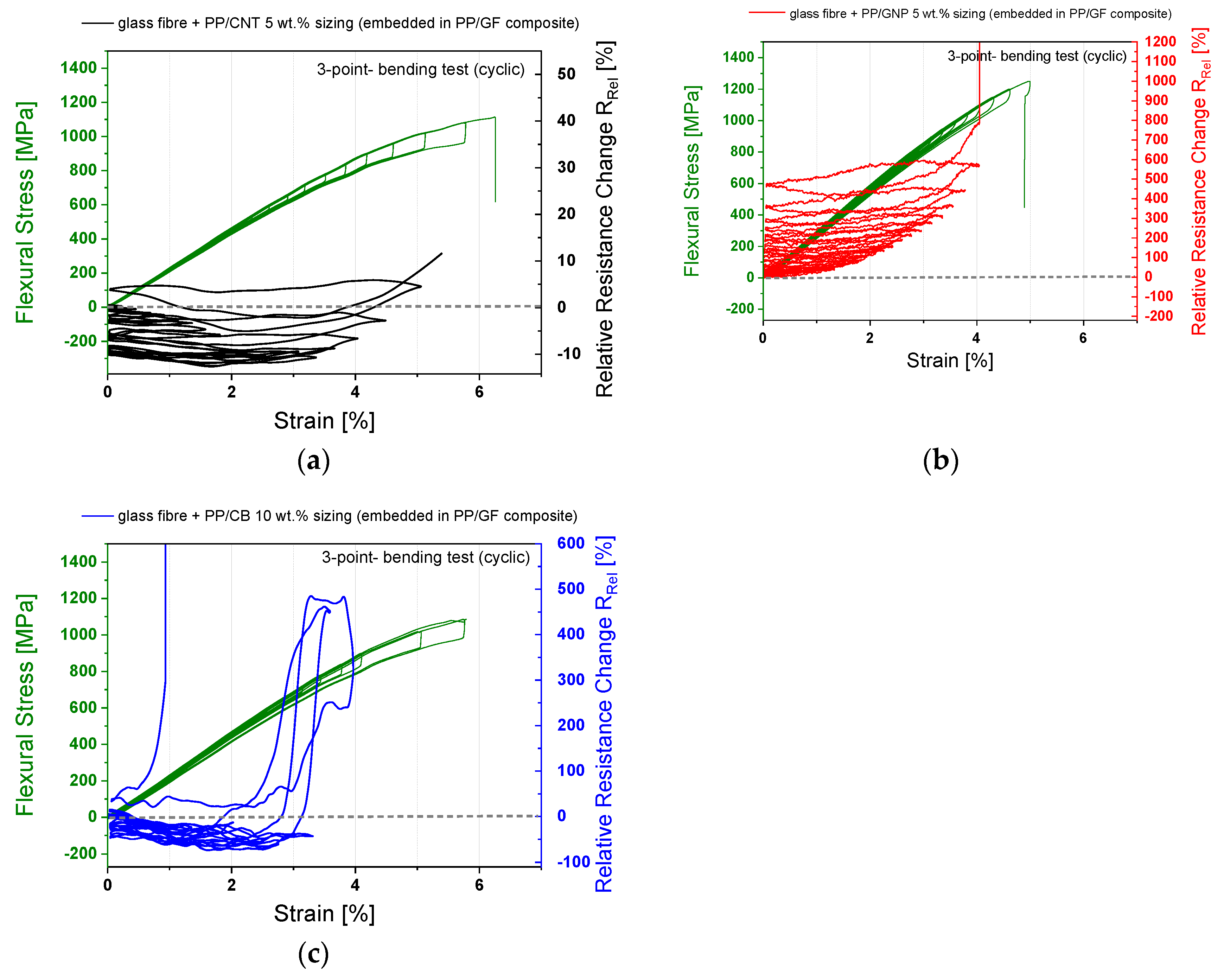
2.1.6. Electro-Mechanical Response during a 3-Point Bending Test

In order to monitor the electro-mechanical response during three-point bending, the sensor fibres, each consisting of a bundle of 204 nanostructured glass filaments, were placed in the neutral plane where typically no compression or tension stresses occur (Figure 3). However, in reality, the sensor fibre is not always placed in the geometric middle, and as a result a mixture of compression and tension stress is applied to the nanostructured fibre. Further, the nanostructured fibre bundle experiences displacement from the exact position by a pressure increase up to 45 bar during the holding-pressure phase, whereby the nanostructured and the normal fibre bundles interfuse partially into each other. If the occurring shear forces are too high, the molten fibre coating can be sheared off and the required conductive pathway will be disturbed. The 3-point bending test was performed in accordance to DIN EN 2562 [48] using rectangular specimens with a length (l) of 80 mm, a width (b) of 20 mm and a height (h) of 1.5 mm. The span length (L) was set to 50 mm. The electrical surface resistance change of the sensor fibres was recorded using a Keithley 2000 electrometer. The data recording was realized by a LabView program on a personal computer.
G F = Δ R R Δ l l
The sensitivity of the sensor fibre was determined by the gauge factor (GF), which is defined by Equation (1), the ratio of relative change in the electrical surface resistance ( Δ R R ) to the relative change of the mechanical strain ( Δ l l ) in the linear range (starting by first signal reply up to 1% deformation).

3. Results and Discussion

The purpose of the study is the development of an in-line nanostructuring glass fibre surface process which enables a higher productivity level. Therefore, the results of the preliminary work on off-line nanostructuring [23] have to be transferred to an in-situ sizing process during continuous fibre melt spinning. In order to realize the process of in-line nanostructuring, the PP/nanofiller emulsion was prepared in the same manner as the off-line nanostructuring process [23]. To compare the influence of different filler morphologies on the electromechanical response behaviour of nanostructured GF, an equivalent state of dispersion is required. Therefore, an ultrasonic treatment time of 60 min was selected for all prepared fibre sizings.
In the first step, the required filler content of the different nanofillers in the electrically over-percolated region (5 wt.% CNT, 5 wt.% GNP and 10 wt.% of CB) was selected in order to achieve a piezo-resistive glass fibre during the in-line structuring process. Even though the electrical percolation threshold of the consolidated PP/nanofiller sizing films are in the range of 1 wt.% and 3 wt.% CNT and GNP and for CB between 7 wt.% and 9 wt.% [23], lower filler contents near the electrical percolation threshold can economize the material expenses. However, they are very sensitive to the processing conditions, and in the worst case, the sensing ability can be lost. In particular, an excessive yarn winding velocity during the fibre drawing process leads to an inhomogeneous and very thin fibre coating. The inhomogeneity can be eliminated by reducing the winding velocity. A problematic thin fibre coating can be additionally optimized by the material characteristic of the sizing system. Since every small imperfection in a thin coating layer can destroy the electrically conductive pathway, a higher filler network density, using an electrically over-percolated sizing system, ensures the sensor reliability by creating more electrical pathways.
In Figure 4, the resulting electrical surface resistivity, measured on in-line nanostructured glass fibres, is plotted against the selected yarn winding velocity during the glass fibre drawing. The yarn winding velocity is directly correlated with the yarn diameter; an increase in speed leads to smaller filament diameters of the yarns.
Typical industrially used glass fibre diameters of 17 µm were obtained at a velocity of 550 m∙min−1. However, at this velocity, the achieved surface resistivity values are too high for a sufficient electro-mechanical-response behaviour. One of the reasons for this might be related to the low transfer of sizing material onto the glass fibres during the in-situ sizing process to form a continuous film along the fibre axis. The percentage numbers in Figure 4 specify the transferred amount of sizing material. To enhance the transfer of sizing materials during the in-situ sizing process, the centrifugal forces at the yarn winder, which act on the organic material and hurl it away, have to be decreased. Otherwise, a large loss of sizing material to the surrounding containment during the melt spinning process will occur. A simple solution is the reduction of the yarn winding velocity during the melt spinning process. Starting from a melt-spinning winding speed of 500 m∙min−1, a decrease of the winding velocity down to 100 m∙min−1 increases the transferred amount of organic material from 2.1 wt.% to 3.6 wt.% using PP/5 wt.% CNT sizing, from 7.8 wt.% to 9.1 wt.% using PP/10wt.% CB sizing and from 2.1 wt.% to 4.8 wt.% using PP/5wt.% GNP sizing (Figure 4). In the case of CNTs, an organic content on the glass fibre surface of more than 2.1 wt.% leads to a continuous conductive pathway along the fibre axes. Using CB or GNP fillers, no continuous pathways are formed, even at larger quantities of sizing material (up to 9.1%) on the glass fibre surface. One reason for this is related to differences in the state of CNT, GNP and CB nanodispersion. Electron-charge-contrast-imaging of nanostructured glass fibres (Figure 5, centre) shows only the filler material which is involved in the electrical network. Charge contrast appears to be related to differences in electronic properties. Therefore, filler materials light up brightly if the filler particles are electrically percolated. The filler material, which did not contribute to the electrical network, did not illuminate in this SEM-mode. The CNTs established a more compact electrical network in comparison to the use of GNP or CB fillers. Furthermore, CNTs are able to bridge imperfections in the surface coating, and such bridging is not obtained using GNP or CB (Figure 5C). Consequently, with CNT fillers, a continuous conductive pathway can be achieved, even in the case of imperfect film formation on the microscale. However, due to the thermal post-processing of the sensor fibre, which takes place during the following consolidation process by compression moulding, the film homogeneity of the GNP and CB coatings on the glass fibre surface can be improved (Figure 6). Thus, the usage of sensor fibres produced at a winding velocity of 100 m∙min−1 exhibits a suitable conductivity for our sensing application. Even if the resistivity value of the CB-coated fibres is not in the targeted range, the electro-mechanical response can be measured by the multimeter which was used. For the preparation of structural monitorable continuous glass fibre reinforced composites, PP/GF hybrid yarns were used. Such a low drawing velocity leads to relatively thick glass fibre diameters, between 30–40 µm, and relatively low fibre mechanical characteristics. Hence, the objective is to realize commonly used diameters of about 17 µm. For this purpose, the glass melt temperature was changed to allow for a homogeneous nanostructuring process at low winding velocities (e.g., 100 m∙min−1 to 250 m∙min−1). In the diameter range below 17 µm, only the use of CNT leads to a piezo-resistive fibre (two-coloured box symbol in Figure 6). However, regarding the establishing of a correlation between filler morphology and signal characteristics, a winding velocity of 100 m∙min−1 is more suitable.
To determine the strain-sensing behaviour of these nanostructured glass fibres, a mechanical 3-point bending test on PP/GF composites was chosen. Therefore, the sensor fibres were embedded in the neutral plane in the centre of the bending test sample (Figure 3). Due to the sensor fibre bundle thickness of around 0.17 mm, the whole fibre is not accurately located in the neutral plane. As a result, a mixture of compression and tensile stress is applied to the nanostructured fibre. Using a static test assembly, the measured electrical resistance shows a clear correlation with the applied mechanical deformation (Figure 7). In such a testing configuration, the differences in the signal quality and sensitivity between respective carbon allotropes can be obtained (Table 2). In comparison to off-line nanostructured fibres [23], the sensitivity or gauge factor of the in-line structured fibre is increased by 5 to 32 times. This is obtained by using a higher filler content of 5 wt.% for CNT and GNP as well as 10 wt.% for CB, which should theoretically lead to lower sensitivity.
This result indicates that the film homogeneity of the in-line produced fibres is too low (Figure 5A). The higher signal scattering in comparison to the off-line structured fibres [23] is also an indication for this. The influence of the filler shape on electrical mechanical response behaviour is reflected in the relative resistance change values of strain at the breaking point (Figure 7). Due to differences in the electrical network density (Figure 5, centre), the CNT-coated fibres show the lowest relative resistance change during the bending test, followed by GNP and CB coating. Another difference in the off-line coated fibres [23] is the break-down of the electro-mechanical response signal before the samples failed, in the case of GNP and CNT filler. Additionally, the determination of the cyclic strain-sensing behaviour of the sensor fibre in PP/GF composites, using different carbon allotropes, was distinguished in order to reveal the reversible and irreversible effects on the sensor signal (Figure 8). With each cycle, the mechanical load was increased stepwise by 50 MPa until the composite failure occurred. The mechanical loading and unloading hysteresis is clearly shown by the sensor signal hysteresis. The GNP material shows the highest sensitivity in this group, and the CNT filler has the lowest one. Interestingly, an irreversible change of resistance in the unstrained state occurs in the unloaded stress mode. This can be attributed to filler reorientation processes caused by polymer creeping and a destruction of electrically conductive paths caused by cracks. For the GNP-coated sensor fibre, the electrical resistance increased with each mechanical loading cycle (Figure 8b), which is an indication that cracks in the GF–PP interphase occurred, which obviously propagate and lead to further crack tip opening, during the dynamic loading. Contrary to this irreversible response, the CNT and CB-based sensor fibres show a combination of reversible and irreversible processes in the interphase (Figure 8a,c).
One reason for this could be the senor fibre position inside the 3-point bending specimen being out of the center, whereby more compression stress acts on the nanostructured fibre. The negative relative resistance response can be caused by creating more electrically conductive pathways when, due to mechanical compression, the previously non-percolated and electrically percolated filler material come into contact. However, the filler shape influence and the filler reorientation behaviour have to be studied more in depth.

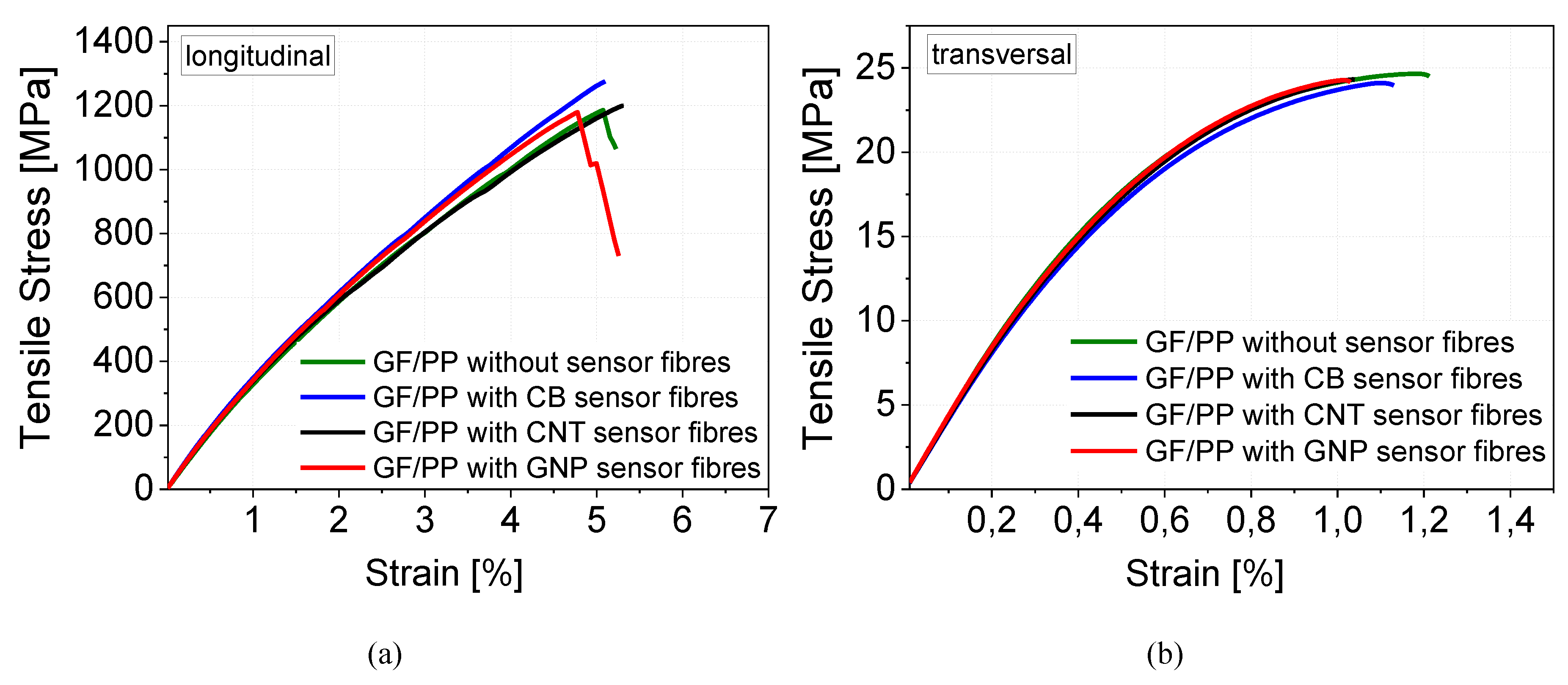
Mechanical Failure Behaviour

Since the in-line nanostructuring of glass fibres for an interface sensor can only be achieved by an increased polymer solid content of 10 to 30 wt.% (normally approx. 0.5 to 3 wt.%) in glass fibre sizing, the influence on the mechanical composite characteristics should be identified. Therefore, continuous reinforced GF/PP composites with one centrally embedded bundle of sensor fibres with increased solid content were produced. In accordance with the DIN 2563 [48] standard, the consolidated plates were cut into test tensile specimens longitudinal and transversal to the fibre orientation. The results reveal that an increased solid content (30 wt.%) of the sizing has no effect on the tensile test values if only one sensor fibre bundle in the GF-reinforced PP composite is used (Table 3 and Figure 9). Also, the embedded nanostructured fibres do not show a significant difference. In contrast, the use of the CB filler leads to a direct failure at the sensor fibre region (Figure 10c). One reason for this might be the higher sizing content of 9.1% in comparison to 4.8% for GNP and 3.6% for CNT (Figure 6).
Therefore, a higher proportion of low-molecular additives, which are mostly tensides to stabilize the water-based PP emulsion, are located on the glass fibre surface. This could be the reason that the weaker interphase between the PP matrix and the nanostructured matrix (Figure 10c) is the starting point of the sample failure.

4. Summary and Conclusions

The glass fibre interphase was successfully nanostructured with different highly electrically conductive carbon allotropes, such as carbon nanotubes, graphene nanoplatelets, or conductive carbon black. Therefore, the glass melt spinning parameters were adapted to ensure a homogeneous and continuous fibre coating to introduce a piezo-resistive feature in the glass fibre interphase. The electro-mechanical response behaviour of the functionalized glass interphase using carbon allotropes shows differences in the signal quality and sensitivity during a 3-point bending test. In comparison to the off-line nanostructured fibres [23], the signal differences are dominated by the differences in the generated lower film homogeneity and not due to the filler shape. Furthermore, the achieved sensitivity (gauge factor) of the in-line fibre is 6 times higher for GNP, 32 times higher for CNT and 20 times higher for CB in comparison to the off-line fibres. The embedding of sensor fibre bundles in GF/PP does not decrease the tensile strength; only the CB nanostructured fibre acts as a stress centre.
To realize a glass fibre diameter of about 17 µm, which is typical for composite applications, the glass melt viscosity was changed by changing the temperature setting. However, due to the possibility of bridging between the polymer domains on the fibre surface, only the use of CNT leads to a piezo-resistive fibre with a diameter of about 17 µm. GNP and CB fillers are not able to connect the separated polymer domains in the same manner. As a consequence, sensor fibres with a diameter of 17 µm cannot be produced in this spinning configuration.

Author Contributions

M.T.M. conceived and designed the experiments; K.E. performed all experiments regarding mechanical failure behaviour; M.T.M., K.E., U.G. and G.H. analyzed all other data and interpreted the results; M.T.M., K.E. and U.G. wrote the paper. All authors read and approved the final manuscript.

Funding

This project was funded by the European Union, project Nanoleap (grant No. Horizon: H2020-NMP-PILOTS-2014; NMP-01-2014).

Acknowledgments

The authors thank Falk Eberth for the glass fibre and hybrid yarn melt spinning. Furthermore, the authors acknowledge the help of Jaqueline Hampel in SEM investigations. In addition, they thank Niclas Wiegand for his profound preparatory work, without which this study would not have been feasible.

Conflicts of Interest

The authors declare no conflict of interest.

References

  1. Allwood, G.; Wild, G.; Hinckley, S. Optical Fiber Sensors in Physical Intrusion Detection Systems: A Review. IEEE Sens. J. 2016, 16, 5497–5509. [Google Scholar] [CrossRef] [Green Version]
  2. Cherif, C.; Häntzsche, E.; Mueller, R.; Nocke, A.; Hübner, M.; Hasan, M. Carbon Fibre Sensors Embedded in Glass Fibre-Based Composites for Windmill Blades; Woodhead Publishing: Sawston, Cambridge, UK. 2016. [Google Scholar]
  3. Gibson, R.F. A review of recent research on mechanics of multifunctional composite materials and structures. Compos. Struct. 2010, 92, 2793–2810. [Google Scholar] [CrossRef]
  4. Häntzsche, E.; Onggar, T.; Nocke, A.; Hund, R.D.; Cherif, C. Multi-Layered Sensor Yarns for in Situ Monitoring of Textile Reinforced Composites; IOP Publishing: Bristol, UK, 2017; Volume 254, p. 042012. [Google Scholar]
  5. López-Higuera, J.M.; Rodriguez-Cobo, L.; Quintela Incera, A.; Cobo, A. Fiber Optic Sensors in Structural Health Monitoring. J. Light. Technol. 2011, 29, 587–608. [Google Scholar] [CrossRef]
  6. Schueler, R.; Joshi, S.P.; Schulte, K. Damage detection in CFRP by electrical conductivity mapping. Compos. Sci. Technol. 2001, 61, 921–930. [Google Scholar] [CrossRef]
  7. Walter, S.E.G. Entwicklung Piezoelektrisch Wirksamer Sensorfasern Auf Basis Von Polyvinylidenfluorid; Shaker Verlag: Maastricht, The Netherlands, 2012. [Google Scholar]
  8. Zhou, G.; Sim, L.M. Damage detection and assessment in fibre-reinforced composite structures with embedded fibre optic sensors-review. Smart Mater. Struct. 2002, 11, 925. [Google Scholar] [CrossRef]
  9. Schubel, P.J.; Crossley, R.J.; Boateng, E.K.G.; Hutchinson, J.R. Review of structural health and cure monitoring techniques for large wind turbine blades. Renew. Energy 2013, 51, 113–123. [Google Scholar] [CrossRef]
  10. Abot, J.; Góngora-Rubio, M.; Anike, J.; Kiyono, C.; Mello, L.; Cardoso, V.; Rosa, R.; Kuebler, D.; Brodeur, G.; Alotaibi, A.; et al. Foil Strain Gauges Using Piezoresistive Carbon Nanotube Yarn: Fabrication and Calibration. Sensors 2018, 18, 464. [Google Scholar] [CrossRef]
  11. Augustin, T. Structural Health Monitoring of Carbon Fiber Reinforced Polymers and Carbon Nanotube Modified Adhesive Joints Via Electrical Resistance Measurement. Ph.D. Thesis, Technische Universität Hamburg, Hamburg, Germany, September 2018. [Google Scholar]
  12. Khan, T.A.; Nauman, S.; Asfar, Z.; Nasir, M.A.; Khan, Z.M. Screen-printed nanocomposite sensors for online in situ structural health monitoring. J. Thermoplast. Compos. Mater. 2018. [Google Scholar] [CrossRef]
  13. Vertuccio, L.; Guadagno, L.; Spinelli, G.; Lamberti, P.; Zarrelli, M.; Russo, S.; Iannuzzo, G. Smart coatings of epoxy based CNTs designed to meet practical expectations in aeronautics. Compos. Part B Eng. 2018, 147, 42–46. [Google Scholar] [CrossRef]
  14. Augustin, T.; Karsten, J.; Kötter, B.; Fiedler, B. Health monitoring of scarfed CFRP joints under cyclic loading via electrical resistance measurements using carbon nanotube modified adhesive films. Compos. Part A Appl. Sci. Manuf. 2018, 105, 150–155. [Google Scholar] [CrossRef]
  15. Al-Sabagh, A.; Taha, E.; Kandil, U.; Nasr, G.-A.; Reda Taha, M. Monitoring Damage Propagation in Glass Fiber Composites Using Carbon Nanofibers. Nanomaterials 2016, 6, 169. [Google Scholar] [CrossRef] [PubMed]
  16. Wang, Y.; Wang, Y.; Wan, B.; Han, B.; Cai, G.; Li, Z. Properties and mechanisms of self-sensing carbon nanofibers/epoxy composites for structural health monitoring. Compos. Struct. 2018, 200, 669–678. [Google Scholar] [CrossRef]
  17. Lu, S.; Tian, C.; Wang, X.; Zhang, L.; Du, K.; Ma, K.; Xu, T. Strain sensing behaviors of GnPs/epoxy sensor and health monitoring for composite materials under monotonic tensile and cyclic deformation. Compos. Sci. Technol. 2018, 158, 94–100. [Google Scholar] [CrossRef]
  18. Moriche, R.; Jiménez-Suárez, A.; Sánchez, M.; Prolongo, S.G.; Ureña, A. Sensitivity, influence of the strain rate and reversibility of GNPs based multiscale composite materials for high sensitive strain sensors. Compos. Sci. Technol. 2018, 155, 100–107. [Google Scholar] [CrossRef]
  19. Ishida, H. A review of recent progress in the studies of molecular and microstructure of coupling agents and their functions in composites, coatings and adhesive joints. Polym. Compos. 1984, 5, 101–123. [Google Scholar] [CrossRef]
  20. Kim, J.-K.; Mai, Y.-w. High strength, high fracture toughness fibre composites with interface control—A review. Compos. Sci. Technol. 1991, 41, 333–378. [Google Scholar] [CrossRef]
  21. Pukánszky, B. Interfaces and interphases in multicomponent materials: Past, Present, Future. Eur. Polym. J. 2005, 41, 645–662. [Google Scholar] [CrossRef]
  22. Zhuang, R.C.; Burghardt, T.; Mäder, E. Study on interfacial adhesion strength of single glass fibre/polypropylene model composites by altering the nature of the surface of sized glass fibres. Compos. Sci. Technol. 2010, 70, 1523–1529. [Google Scholar] [CrossRef] [Green Version]
  23. Müller, M.; Pötzsch, H.; Gohs, U.; Heinrich, G. Online Structural-Health Monitoring of Glass Fiber-Reinforced Thermoplastics Using Different Carbon Allotropes in the Interphase. Materials 2018, 11, 1075. [Google Scholar] [CrossRef]
  24. Rausch, J.; Mäder, E. Health monitoring in continuous glass fibre reinforced thermoplastics: Tailored sensitivity and cyclic loading of CNT-based interphase sensors. Compos. Sci. Technol. 2010, 70, 2023–2030. [Google Scholar] [CrossRef] [Green Version]
  25. Rausch, J.; Mäder, E. Health monitoring in continuous glass fibre reinforced thermoplastics: Manufacturing and application of interphase sensors based on carbon nanotubes. Compos. Sci. Technol. 2010, 70, 1589–1596. [Google Scholar] [CrossRef] [Green Version]
  26. Rausch, J.; Mäder, E. Carbon nanotube coated glass fibres for interphase health monitoring in textile composites. Mater. Technol. 2011, 26, 153–158. [Google Scholar] [CrossRef]
  27. Wiegand, N.; Mäder, E. Multifunctional interphases for sensing applications in glass fiber polypropylene composites. In Proceedings of the CAMX, Orlando, FL, USA, 13–16 October 2014. [Google Scholar]
  28. Wiegand, N.; Mäder, E. Multifunctional Interphases: Percolation Behavior, Interphase Modification, and Electro-Mechanical Response of Carbon Nanotubes in Glass Fiber Polypropylene Composites. Adv. Eng. Mater. 2016, 18, 376–384. [Google Scholar] [CrossRef]
  29. Zhang, J.; Zhuang, R.; Liu, J.; Scheffler, C.; Mäder, E.; Heinrich, G.; Gao, S. A Single Glass Fiber with Ultrathin Layer of Carbon Nanotube Networks Beneficial to In-Situ Monitoring of Polymer Properties in Composite Interphases. Soft Mater. 2014, 12, S115–S120. [Google Scholar] [CrossRef]
  30. Zhang, J.; Liu, J.; Zhuang, R.; Mäder, E.; Heinrich, G.; Gao, S. Single MWNT-Glass Fiber as Strain Sensor and Switch. Adv. Mater. 2011, 23, 3392–3397. [Google Scholar] [CrossRef]
  31. Can-Ortiz, A.; Abot, J.L.; Avilés, F. Electrical characterization of carbon-based fibers and their application for sensing relaxation-induced piezoresistivity in polymer composites. Carbon 2019, 145, 119–130. [Google Scholar] [CrossRef]
  32. Liu, L.; Ma, P.-C.; Xu, M.; Khan, S.U.; Kim, J.-K. Strain-sensitive Raman spectroscopy and electrical resistance of carbon nanotube-coated glass fibre sensors. Compos. Sci. Technol. 2012, 72, 1548–1555. [Google Scholar] [CrossRef]
  33. Boehle, M.; Jiang, Q.; Li, L.; Lagounov, A.; Lafdi, K. Carbon nanotubes grown on glass fiber as a strain sensor for real time structural health monitoring. Int. J. Smart Nano Mater. 2012, 3, 162–168. [Google Scholar] [CrossRef] [Green Version]
  34. Sebastian, J.; Schehl, N.; Bouchard, M.; Boehle, M.; Li, L.; Lagounov, A.; Lafdi, K. Health monitoring of structural composites with embedded carbon nanotube coated glass fiber sensors. Carbon 2014, 66, 191–200. [Google Scholar] [CrossRef]
  35. Boehle, M.C. Synthesis and Characterization of a Carbon Nanotube Based Composite Strain Sensor. Master’s Thesis, University of Dayton, Dayton, OH, USA, May 2016. [Google Scholar]
  36. Rausch, J.; Zhuang, R.C.; Maeder, E. Systematically varied interfaces of continuously reinforced glass fibre/polypropylene. Express Polym. Lett. 2010, 4, 576–588. [Google Scholar] [CrossRef]
  37. Mäder, E.; Rausch, J.; Schmidt, N. Commingled yarns—Processing aspects and tailored surfaces of polypropylene/glass composites. Compos. Part A Appl. Sci. Manuf. 2008, 39, 612–623. [Google Scholar] [CrossRef]
  38. Krause, B.; Mende, M.; Pötschke, P.; Petzold, G. Dispersability and particle size distribution of CNTs in an aqueous surfactant dispersion as a function of ultrasonic treatment time. Carbon 2010, 48, 2746–2754. [Google Scholar] [CrossRef]
  39. Nanocyl, NC7000 Series—Product Datasheet—Thin Multi-Wall Carbon Nanotubes; Nanocyl SA: Sambreville, Belgium, 2010.
  40. Müller, M.; Hilarius, K.; Liebscher, M.; Lellinger, D.; Alig, I.; Pötschke, P. Effect of Graphite Nanoplate Morphology on the Dispersion and Physical Properties of Polycarbonate Based Composites. Materials 2017, 10, 545. [Google Scholar] [CrossRef] [PubMed]
  41. Graphit-Kropfmühl, Datasheet—Multilayer graphene EXG 98 300; Graphit Kropfmühl GmbH: Hauzenberg, Germany, 2013.
  42. Carbons, O.E. Datasheet—Printex XE2B; Orion Engineered Carbons GmbH: Frankfurt am Main, Germany, 2010. [Google Scholar]
  43. ASTM-D257. Standard Test Methods for DC Resistance or Conductance of Insulating Materials; ASTM: West Conshohocken, PA, USA, 2014. [Google Scholar]
  44. DIN EN ISO 14125. Faserverstärkte Kunststoffe-Bestimmung der Biegeeigenschaften, 5th ed.; DIN Deutsches Institut für Normung e. V.: Berlin Germany, 2011. [Google Scholar]
  45. DIN EN ISO 527. Kunststoffe-Bestimmung der Zugeigenschaften-Teil 1: Allgemeine Grundsätze, 6th ed.; DIN Deutsches Institut für Normung e. V.: Berlin Germany, 2012. [Google Scholar]
  46. ISO 9291. Textile-Glass-Reinforced Plastics-Rovings-Preparation of Unidirectional Plates by Winding, 10th ed.; DIN Deutsches Institut für Normung e. V.: Berlin Germany, 1996. [Google Scholar]
  47. Wiegand, N.; Mäder, E. Commingled Yarn Spinning for Thermoplastic/Glass Fiber Composites. Fibers 2017, 5, 26. [Google Scholar] [CrossRef]
  48. DIN EN 2563. Aerospace series-Carbon Fibre Reinforced Plastics-Unidirectional Laminates; Determination of Apparent Interlaminar Shear Strength; DIN Deutsches Institut für Normung e. V.: Berlin Germany, 1997. [Google Scholar]
Figure 1. Sensor fibre bundle (204 nanostructured glass filaments) placement in a rectangular mandrel (with (Left) and without (Right) silver paint pattern for improved conductivity) with adhesive tape during the glass fibre (GF)/ polypropylene (PP) unidirectional composite winding process.
Fibers 07 00061 g001
Figure 2. Set heating rate and the resulting actual temperature of the compression moulding process.
Fibers 07 00061 g002
Figure 3. Test device, specimen and sensor layout (sensor fibre embedded in the neutral plane) for the three-point bending test on a rectangular unidirectional GF/PP composite with the fibres in the direction of the specimen’s length axis.
Fibers 07 00061 g003
Figure 4. Influence of the winding velocity during the fibre spinning process on electrical resistivity, measured on in-line nanostructured glass fibres (small percentage numbers specifies the organic content on the fibre surface). CNT: carbon nanotube; CB: carbon black.
Fibers 07 00061 g004
Figure 5. SEM pictures of nanostructured glass fibre bundles (drawing velocity 100 m/min) using 5 wt.% CNT, GNP and 10 wt.% CB sizing. (A) Charge-contrast imaging to illustrate the electrical network density (B) and magnified SEM pictures (C) to provide information regarding the filler bridge ability between separate polymer islands.
Fibers 07 00061 g005
Figure 6. Influence of the winding velocity during the fibre spinning process on electrical resistivity, measured on in-line nanostructured glass fibres which are embedded into continuous polypropylene/glass fibre composites via compression molding (small percentage numbers specify the organic content on the fibre surface).
Fibers 07 00061 g006
Figure 7. Electro-mechanical response behaviour of in-line nanostructured sensor fibre using 5 wt.% CNT embedded in the neutral plane zone, during a static 3-point bending test (span to length L/h ratio of 33).
Fibers 07 00061 g007
Figure 8. Cyclic electro-mechanical response behaviour of in-line nanostructured sensor fibre using 5 wt.% CNT (a), 5 wt.% GNP (b) and 10 wt.% CB (c) embedded in the neutral plane zone during a quasi-static 3-point bending test (span to length L/h ratio of 33, a stepwise increase of mechanical loading of 50 MPa).
Fibers 07 00061 g008
Figure 9. Representative tensile curves for tensile behaviour, longitudinal (a) and transversal (b) of a unidirectional GF/PP composite with one centrally embedded sensor fibre (nanostructured with 5 wt.% CNT, 5 wt.% GNP and 10 wt.% CB, respectively); representative tensile curves are shown.
Fibers 07 00061 g009
Figure 10. Fracture patterns of unidirectional PP/GF hybrid yarn composite with an embedded sensor fibre bundle (transversal tensile test, type B); horizontal tensile direction.
Fibers 07 00061 g010
Table 1. Specifications of the used commercial carbon filler material powders.
Material as Named by the Producer/ProducerMorphologyAverage Particle Size d50 [µm]Thickness/DiameterElectrical Conductivity [S∙cm−1]Specific Surface [m2∙g−1]Bulk Density [kg∙m−3]
Nanocyl™ NC7000 (CNT) Nanocyl S.A. Fibre>675 [38]Ø 9.5 nm [39]15 [40] *2250–300 [39]66 [38]
EXG 98 300 (GNP) Graphit KropfmühlLamellar305 *3-3 [40] *2>300 [41]1 *1
Printex XE2B (CB) Orion Engineered CarbonsSpherical60 *3Ø 30–35 nm [42]20 [40] *21000 [42]100–400 [42]
*1 In-house measurement according to EN 1097-3 *2 at 30 MPa compression pressure *3 In-house laser diffraction measurement.
Table 2. Sensitivity values (gauge factor) of in-line nanostructured fibres in a linear range (up to 1% strain) of nanostructured sensor fibres using different carbon filler (CNT, GNP, CB) embedded in the neutral plane zone during a quasi-static 3-point bending test; the gauge factor is the ratio of relative change in electrical surface resistance (∆R/R) to the mechanical strain (∆l/l).
SampleGauge Factor (Neutral Plane Zone)
CNT (5 wt.%)650
GNP (5 wt.%)670
CB (10 wt.%)390
Table 3. Mechanical properties of GF/PP (50/50 vol.%) composites with an embedded nanostructured fibre bundle (CNT, GNP, CB) (the values given represent mean values of 7 measurements).
SampleEt [MPa]σB [MPa]εB [%]
GF/PP, transversal4399 ± 7424.7 ± 0.61.2 ± 0.1
GF/PP + CNT fibre, transversal4176 ± 5424.3 ± 0.71.1 ± 0.1
GF/PP + GNP fibre, transversal4291 ± 6624.4 ± 0.61.0 ± 0.1
GF/PP + CB fibre, transversal4172 ± 11924.5 ± 0.81.1 ± 0.1
GF/PP, longitudinal36,923 ± 12791201 ± 515.4 ± 0.4
GF/PP + CNT fibre, longitudinal38,251 ± 16221164 ± 805.3 ± 0.4
GF/PP + GNP fibre, longitudinal40,283 ± 6831188 ± 794.9 ± 0.5
GF/PP + CB fibre, longitudinal41,676 ± 5621250 ± 265.0 ± 0.2

