Analysis of the Behavior of FRCM Confined Clay Brick Masonry Columns


Department of Civil Engineering, University of Calabria, Bucci Bridge, Building 39B, Arcavacata di Rende, 87036 Cosenza, Italy
*
Author to whom correspondence should be addressed.
Fibers 2020, 8(2), 11; https://0-doi-org.brum.beds.ac.uk/10.3390/fib8020011
Submission received: 27 December 2019
/
Revised: 3 February 2020
/
Accepted: 5 February 2020
/
Published: 10 February 2020
Abstract
:The behavior of FRCM (Fabric Reinforced Cementitious Mortar) confined clay brick masonry columns is analyzed in this paper. The results of an experimental investigation conducted on small-scale columns made by clay brick masonry confined with steel-FRCM (or Steel Reinforced Grout, SRG), PBO (poly-paraphenylene-benzo-bisoxazole) FRCM and basalt-FRCM, tested under monotonic compressive load, are described and discussed. Tests were conducted on thirteen prismatic columns; eleven columns (two unconfined and nine confined) were tested under concentric load while an eccentric load was applied on two confined columns. For each confinement system, the parameters investigated were the ‘confinement ratio’, the ‘load eccentricity’ and the ‘overlap configuration of the fiber fabrics’. FRCM confinement improved the structural response of masonry columns in terms of ultimate strength, ultimate strain and ductility. Some models from the literature were also examined to evaluate their applicability in predicting the axial capacity of confined columns.
1. Introduction
Composite materials consisting of unidirectional or bidirectional fiber fabrics with inorganic matrices, have recently been widely used to strengthen or retrofit existing structures. These new families of inorganic matrix composites are, generally identified as Fabric Reinforced Cementitious Mortar (FRCM) or Textile Reinforced Mortar (TRM) when carbon, PBO (short of polyparaphenylenebenzobisoxazole), glass or basalt bidirectional fiber fabrics are used and, Steel Reinforced Grout (SRG) when unidirectional steel cords are used.
FRCM/TRM and SRG composites have good mechanical properties and exhibit excellent durability performances; in addition, they are easily applicable, are compatible with both concrete and masonry substrates and their workability is assured in a wide range of temperatures [1,2,3]. These features make the use of FRCM and SRG effective in the strengthening of concrete and masonry structures.
Studies and research results evidenced the good mechanical properties of FRCM/SRG strengthened masonry [4,5,6,7,8,9] and concrete structures [10,11,12,13,14].
The behavior of FRCM/SRG confined masonry columns has extensively been investigated mainly by experimental research. Tests have been conducted on columns under both concentric and eccentric loads varying geometrical and mechanical parameters. In most cases clay brick masonry columns confined with Carbon-FRCM [15,16], basalt FRCM [17,18,19], PBO-FRCM [20], glass-FRCM [18,21,22], and SRG jackets [18,23,24] have been tested. The main parameters investigated were the confinement ratio (i.e., the number of confining plies) [15,16,23], the mortar grade [20,21,22], the corner radius [16,24], the masonry grade [17], the brick configuration [20] and the load eccentricity [15,23].
In particular tests performed by Ombres [15] and Ombres and Verre [23] on carbon FRCM-and SRG confined clay brick columns, respectively, subjected to axial and eccentric load, highlight that for axially loaded columns strength and ductility values are increasing with the confinement ratio while they are decreasing with the increase of the load eccentricity. In addition, a FEM procedure adopted to perform a numerical analysis furnished satisfactory predictions of the axial capacity of confined columns [23].
An experimental and analytical study on masonry columns confined with carbon fiber fabrics in polymer-modified cement binder has been conducted by Krevaikas [16]. Short masonry columns have been tested under concentric loading varying the number of confining layers, the cross-section aspect ratio and the corner radii. Tests results have been used to develop simple models (both linear and nonlinear) for the prediction of the ultimate strength and strain of confined columns.
The influence of different brick configurations on the behavior of PBO-FRCM confined brick masonry columns was investigated by Carloni et al. [20] through the results of tests conducted on full-scale and scaled bricks columns. The parameters investigated were also the role of the mortar joints and the arch effect across the section of the columns due to the confinement.
Cascardi et al. [21] used three different inorganic matrices for confining poor quality masonry columns tested under axial load. The experimental results confirmed that the FRCM confinement may produce a significant improvement of the mechanical properties of the masonry columns when a proper grade of mortar matrix is used.
The compressive behavior of calcarenite masonry columns confined with different FRCM systems was analyzed by Minafò and La Mendola [22]. The confinement system made with glass fiber fabric was changed on the basis of the mechanical properties of the mortar. The results of tests evidenced the role of the mortar grade on the strength, strain and ductility of confined columns. An analytical model, found based on an iterative procedure, was also proposed to predict the overall compressive behavior of FRCM confined masonry columns.
The results of tests conducted by Fossetti and Minafò [17] on basalt-FRCM confined masonry columns evidenced that the use of basalt-FRCM jackets was effective in enhancing the strength only for low grade masonry columns while for normal strength masonry columns it was effective in increasing the energy absorption but it had a limited effect on the increase of the axial capacity.
Clay masonry columns confined with one SRG layer, were subjected to axial load varying the density of steel fibers and the column corner radius were tested by Sneed et al. [24]. The results of the investigation evidenced the increase of the axial capacity of SRG confined columns with both corner radius ratio and fiber density.
Basalt and steel-FRCM confined masonry columns with a square cross-section were tested under monotonic axial compression load also by Santandrea et al. [19]. Both basalt and steel fibers provided an increase of the average numeration compressive strength with respect to un-confined specimens: the increase was equal to 14%–16% for basalt fibers and 33% for steel fibers. The lower performances of basalt fibers were attributed to the brittle nature and the relatively low tensile strength of the basalt fibers that tend to rupture near the corners of the columns.
An extensive and detailed state-of-the-art of the behavior of FRCM confined masonry columns is reported on the document [25] elaborated by the ACI 549 and RILEM TC 250 liaison subcommittee. The document, based on the results of experimental investigations, analytical research and field applications provides the recommendations for the design of FRCM according American and European regulations and guidelines.
Statistical analyses of experimental results are also performed to define predictive models of the performances of FRCM confined masonry columns. Among those there are the designed-oriented model (DOM) proposed by Cascardi et al. [26] developed by a multiple linear regression approach and the semi-empirical models proposed by Kreivaikas and Triantafillou [27], Di Ludovico et al. [28], Fossetti and Minafò [17], Krevaikas [16], Minafò and La Mendola [22], and the Italian CNR-DT 215 guidelines [29]. Due to their semi-empirical nature, moreover, these models are dependent on many variables affecting the behavior of confined masonry columns which cannot furnish reliable predictions for all types of FRCM-confined masonry columns. The availability of experimental results is, then, essential in evaluating the effectiveness of the FRCM confinement varying the physical and mechanical parameters involved and improving prediction models.
This paper reports the results of a comparative study on the experimental performances of axially loaded FRCM confined small-scale clay brick masonry columns. Three FRCM systems (Steel –FRCM or Steel Reinforced Grout, SRG, PBO-FRCM and basalt-FRCM) were adopted as confining systems. The influence of some geometrical and mechanical parameters such as the number of confining layers, the load eccentricity and, the confinement configurations on the failure modes, peak loads, strains and ductility of confined columns was analyzed and discussed. The parameters investigated in this study were not considered in previous studies, in which in most cases axially loaded masonry columns confined with a single layer of FRCM were analyzed and the influence of fiber overlap along the column’s height was not considered. Test results described and discussed in the paper, even if limited (particularly for the eccentric loaded specimens), evidenced that: (i) all the considered FRCM systems are effective in confining the masonry columns, (ii) the structural response of columns was different for each confining FRCM system and, (iii) the confinement effectiveness is strongly influenced by both the confinement ratio and the confinement configuration.
2. Materials and Methods
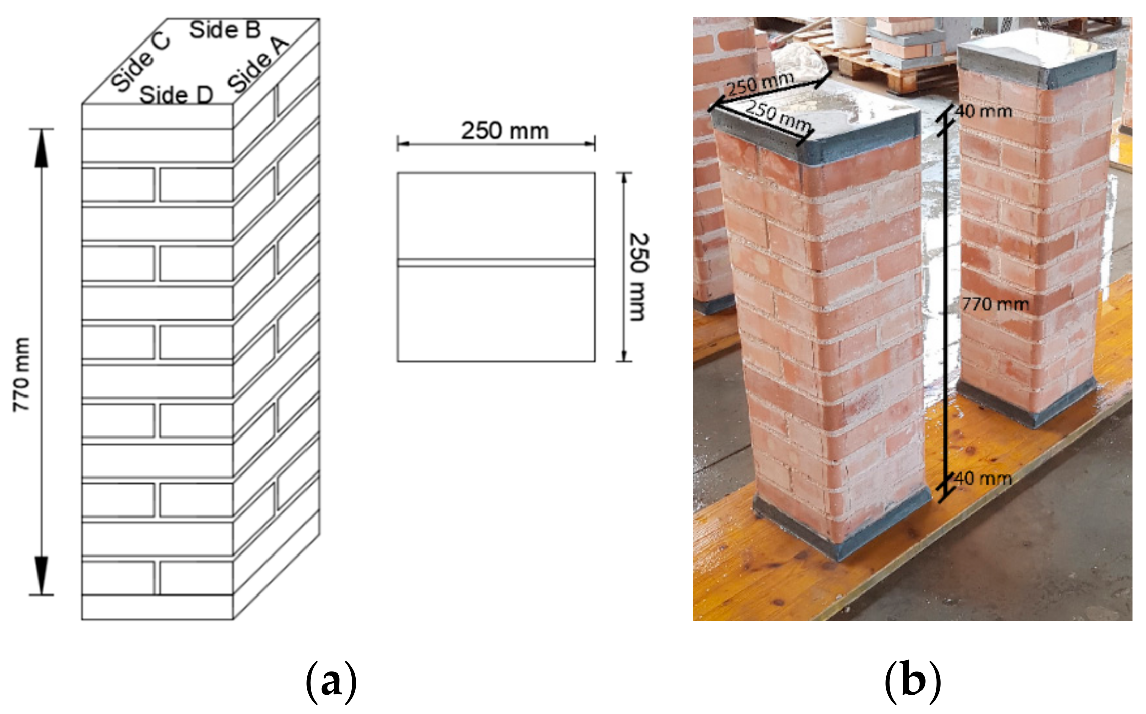
Thirteen masonry columns, two unconfined and eleven confined with three different FRCM systems, with square cross-section 250 mm wide and 770 mm high were tested. To analyze the influence of the confinement ratio height columns were tested under concentric axial load (three columns confined with PBO, three columns confined with SRG and two columns confined with basalt FRCM. Due to local defects, a third column confined with three layers of basalt-FRCM was destroyed during the test and it was not considered in this analysis). The remaining three columns were confined with SRG and used to evaluate the influence of the load eccentricity and the confining configuration. Consequently, six columns were confined with SRG (4 concentrically loaded and 2 eccentrically loaded), three with PBO-FRCM and two with basalt-FRCM. Figure 1 illustrates the geometry of unconfined specimens.
The experimental investigation conducted on PBO-FRCM and basalt-FRCM is described in this paper while the one carried out on SRG confined columns was described in details in a previous paper [21]. The comparative analysis of test results reported in the following sections, refers to all tested confined specimens.
The designation C-X-Y-μ-Z, where C indicates the confined specimen, X the type of fibers; Y the number of layers; μ (where present) the eccentricity value and Z the specimen number was used to identify the confined columns. UC1 and UC2 labels identify the two unconfined columns. Details of the tested specimens are reported in Table 1.
2.1. Materials
2.1.1. Binding Mortar and Clay Brick Units
Commercial clay bricks were used to assemble the masonry column; the single brick unit has nominal dimensions 250 × 120 × 55 mm3. According to the UNI EN 772-1 [30] standard compression tests were performed on 5 bricks to determine their mechanical properties. The average value of the compression strength was 56.8 MPa (CoV = 0.02).
A low strength mortar was used to bind the clay units of the masonry columns. The average values of the compression and flexural strength of the low strength mortar, determined by tests on three 40 × 40 × 160 mm3 prisms according to UNI EN 12190:2000 [31] and UNI EN 1015-11 [32], were 3.32 MPa (CoV = 0.07) and 1.22 MPa (CoV = 0.04), respectively.
2.1.2. FRCM Systems
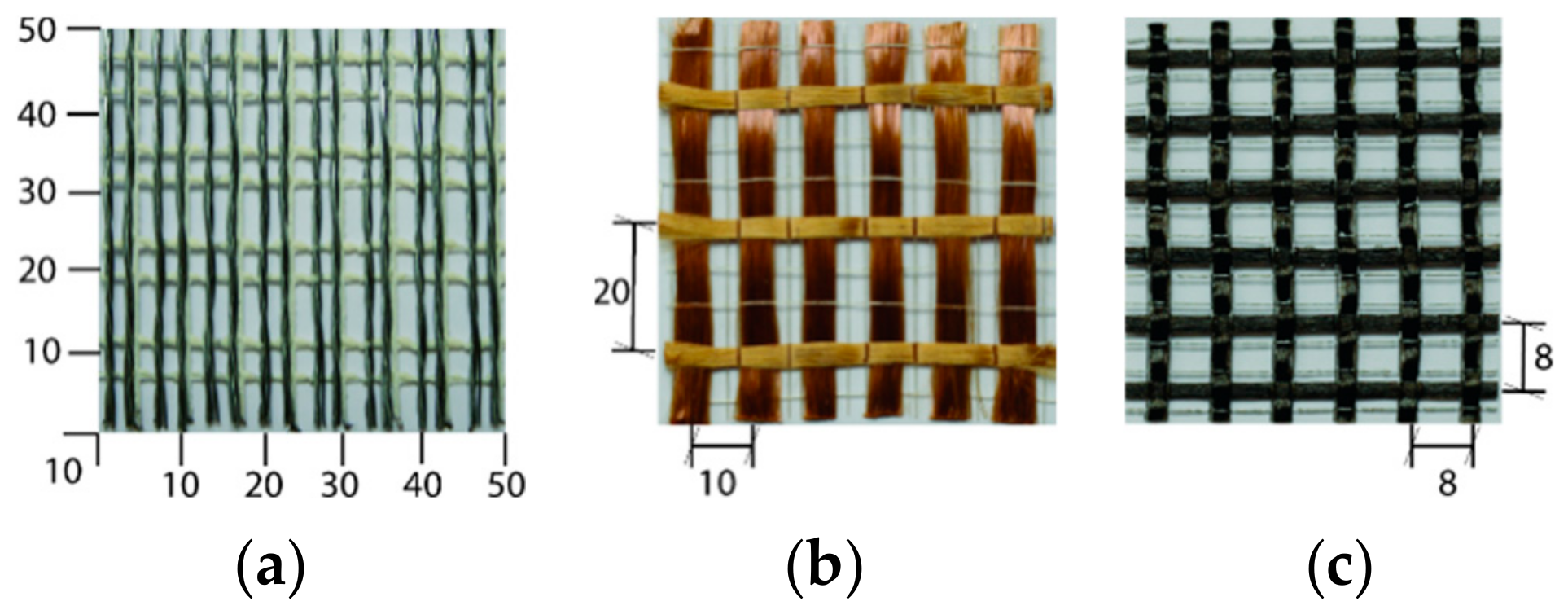
All confining systems were furnished by the manufacturers which are available on the market. The SRG and basalt-FRCM systems were composed by open meshes of twisted high-strength galvanized steel cords and basalt meshes, respectively, and a mineral-NHL mortar. The PBO-FRCM system consisted of PBO unbalanced fabrics embedded in a cementitious matrix. Figure 2 shows the configuration of textiles.
The SRG system used in this investigation has the fiber density of 1200 g/m2 and the equivalent thickness, t, equal to 0.169 mm.
The density of the basalt fabric is 400 g/m2, while yarns are spaced 0.8 mm in both directions. The equivalent thickness of the basalt fabric is 0.064 mm. Basalt and steel fibers combine with a hydraulic mineral-NHL mortar, containing kaolin, bauxite and hydraulic lime binder.
The equivalent thickness of the PBO fabric mesh is 0.046 mm in the longitudinal (principal) direction and 0.012 mm in the transversal direction. The fiber bundles were spaced 10 mm and 20 mm in the principal and orthogonal direction, respectively. In addition, the width of a single fiber bundle, b, is equal to 5 mm while a pozzolana mortar is used as matrix of the PBO FRCM system.
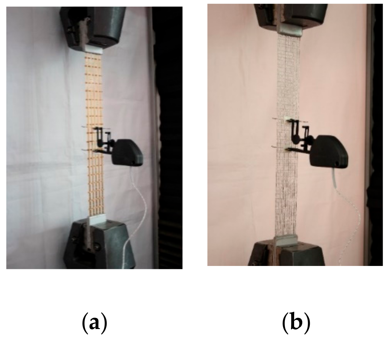
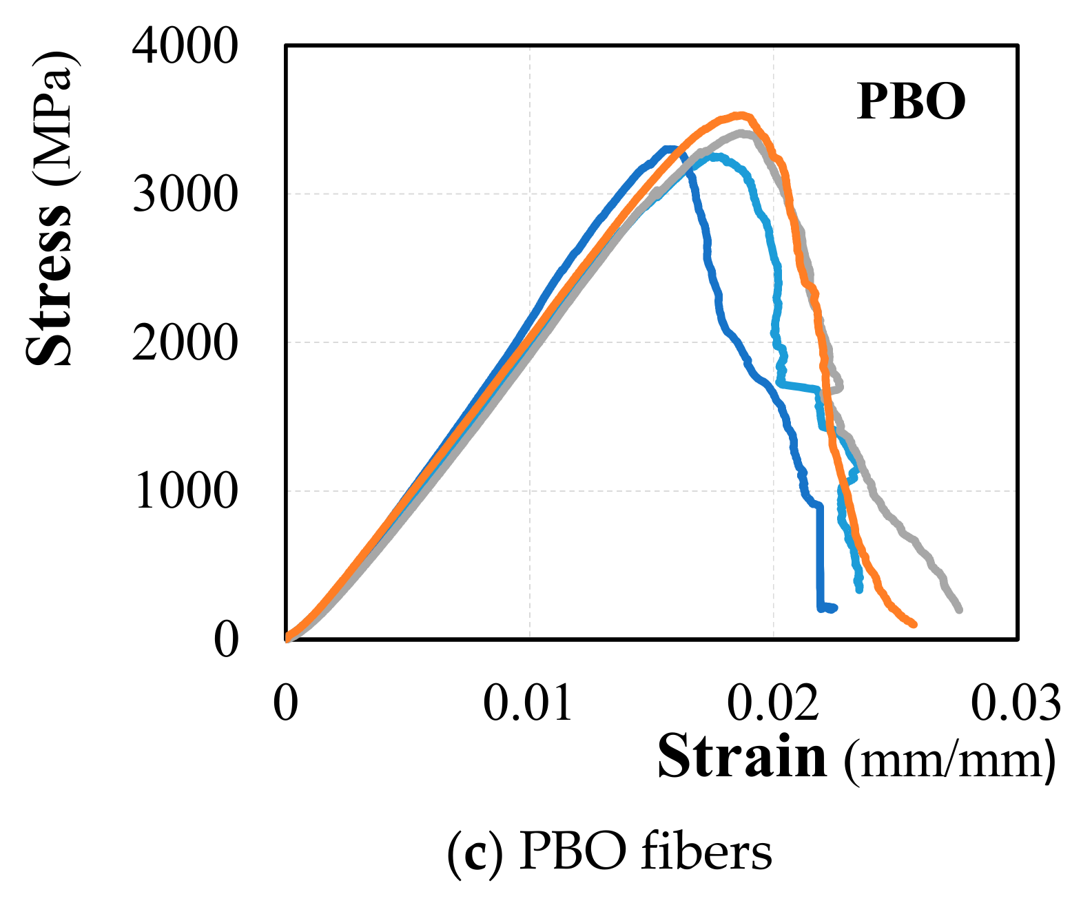
According to the Italian guidelines [29], tensile tests were carried out on 5 specimens of each type of fiber to determine their mechanical characteristics. The adopted test set-up is illustrated in Figure 3. Two pairs of aluminum plates were attached by a thermosetting epoxy at both ends of the dry textile strip to grip the bare fibers and to ensure a homogeneous stress distribution during the test. Both ends were clamped, and the load was applied at one of the ends. To evaluate the local strain, an extensometer with 50 mm of gauge length was placed in the middle of a 360 mm dry textile in accordance to [29]. The tests were displacement controlled at a rate of 0.005 mm/s.
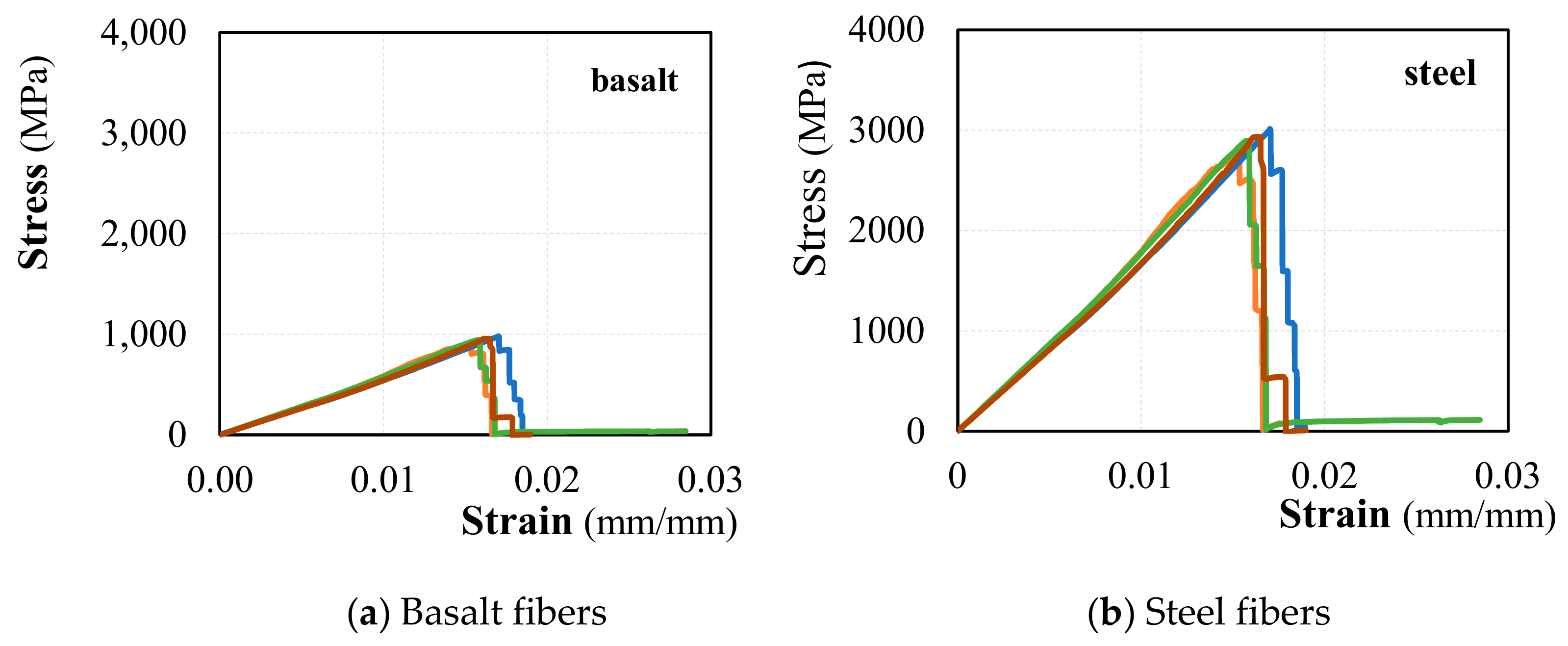
The main mechanical parameters were summarized in Table 2; stress-strain curves determined by tests were reported in Figure 4 for each type of fiber.
Mechanical properties of the mineral-NH mortar and the pozzolana mortar were determined by tests conducted the UNI EN 12190:2000 [31] and UNI EN 1015-11 [32] provisions. Average and coefficient of variation values of strength obtained by tests are illustrated in Table 3.
Elastic modulus, tensile strength, and ultimate strain of each FRCM systems investigated, were determined by tensile tests on five prismatic coupons with a nominal size of 510 × 50 × 10 mm3. Each specimen was made individually so that the constant thickness for the entire length was ensured. The dry textile was placed in the middle of the coupon; the steel sheet of the SRG system was composed of 16 micro-cords while the fabric meshes of PBO and basalt were composed of 5 and 6 yarns, respectively. Furthermore, after 7 days the specimens were de-molded and they were stored and cured in laboratory for 28 days. Two aluminum tabs 100 mm length were attached at the ends of each coupon to ensure a good stress arrangement during the test and to avoid damages in the sample. Tests were conducted in stroke control; the slip was measured by two LVDTs placed on the entire gauge length. Results of tests are reported in Table 4.
2.2. Specimens Preparation
Masonry columns were built assembling clay brick units through a low strength mortar (see Figure 1). The mortar joint was 10 mm thick.
To simplify the installation of the fabric/sheet layers a 20 mm corner radius was executed in each column. To avoid geometrical imperfections during the load application, a 40 mm thick layer of high strength, self-leveling mortar was placed at the top and bottom ends of the columns.
Before the application of the FRCM jacket the columns were accurately wet. Immediately after the first mortar layer was applied, a single sheet/fabric mesh was hand-pressed slowly to ensure an adequate impregnation and enveloped around the column. Another layer of mortar was, then applied (Figure 5). The procedure was repeated for each fabric layer. Each mortar layer was approximately 3 mm thick.
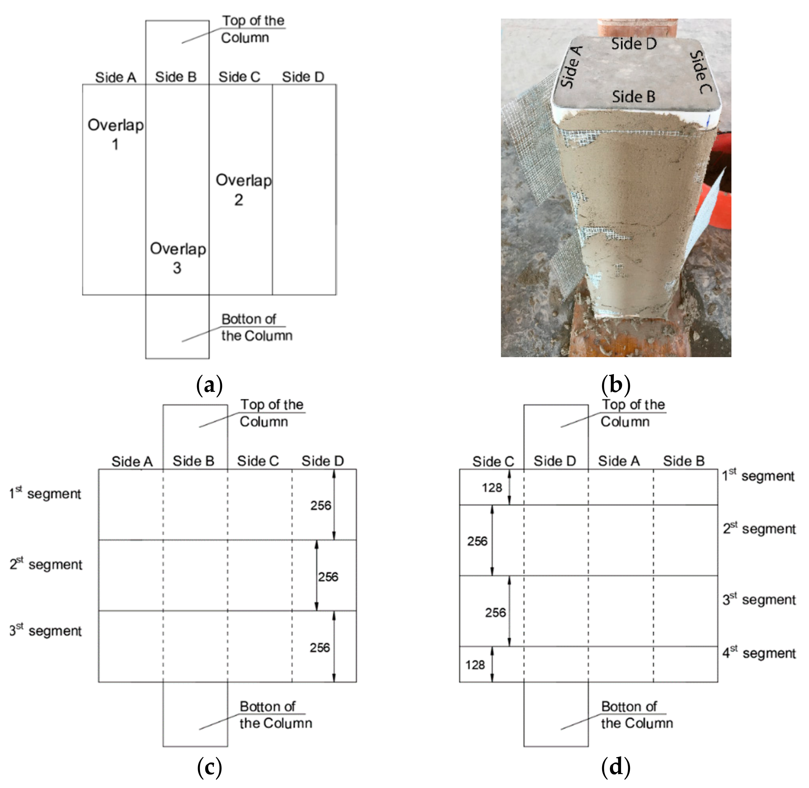
The overlap of each confining layer along the height of the columns was defined accurately to avoid the formation of vertical lines of stitching near the corners. The adopted solution is illustrated in Figure 6. Commercial SRG fabrics were 300 mm in height and, then, for each SRG layer, three or four steel fabric segments which overlapped both in transversal and longitudinal direction were needed to confine the whole column. In particular, the wrapping of specimens with 1-layer and 3-layer jackets were made by three steel fabric segments (Figure 6c) while four steel fabric segments were employed for 2-layers confined specimens (Figure 6d).
Specimens wrapped with PBO and basalt needed of only one segment being the height of fabrics were higher than the column’s height.
The overlap zone for specimens wrapped with one layer of fabric (C-S-1-0-1, C-P-1-0, C-B-1-0, C-S-1-25 and C-S-1-50 specimens) was on the side A; for specimens strengthened with two layers (C-S-2-0, C-P-2-0 and C-B-2-0 specimens), the inner layer was overlapped on the side A and the outer one on the side C; for three layers wrapped specimens (C-S-3-0, C-P-3-0 specimens), the overlap zones were on the sides A, C, and B, for inner, intermediate and outer layers, respectively. Furthermore, particular attention has been put on how to apply the steel fiber sheet in order to evaluate the effects of the local position of the overlap. To evaluate the effect of the overlap configuration the C-S-1-0-2 specimen, was confined differently with respect to the C-S-1-0-1 specimen (both were confined with one SRG layer): the 1st and the 3rd segments of the steel fabric were overlapped on side A (see Figure 6), while the 2nd one was overlapped on side C. For all tested columns the overlap width was equal to the width of the sides (250 mm) in the horizontal direction for all confining systems while steel fabric segments were not overlapped in the vertical direction. The columns were cured in the laboratory and tested 28 days after their casting.
2.3. Test Set-Up
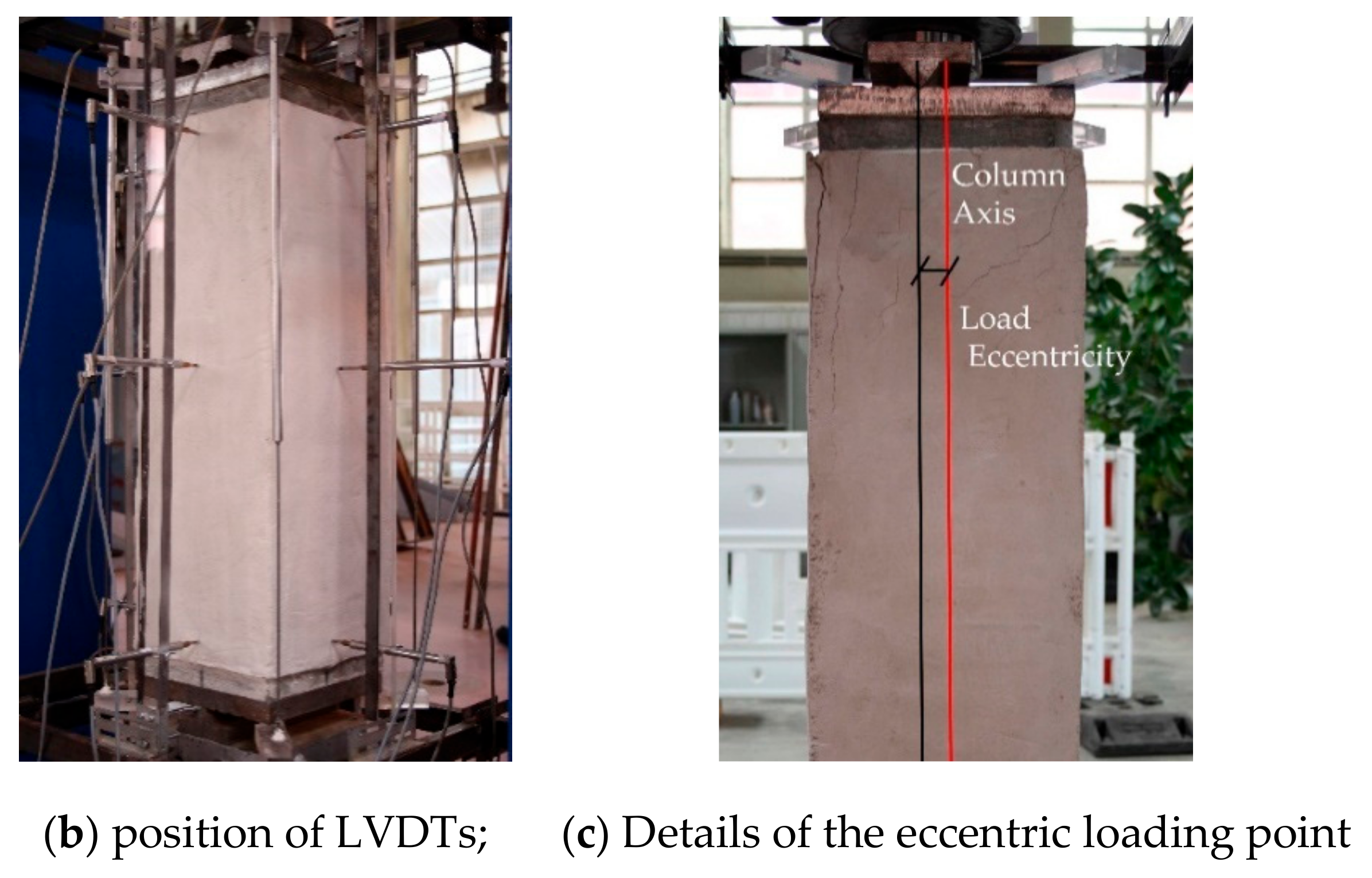
A hydraulic jack and load cell of 1000 kN was used to test the columns. A system composed of a steel plate with knife-edge and an adapter steel plate (both 20 mm thick) was applied both at the top and at the bottom of the specimens. The plate receives the compression load by the hydraulic jack and transfers it to the adapter plate located on the specimen. Few V-notch grooves were made on the adapter plate at both the mid-length (concentric loading) and the locations corresponding to the assumed eccentricity values (eccentric loading). A high strength mortar was used to cap the top and the bottom of the columns to guarantee that they were in plane and parallel. Tests were conducted through monotonically applied loading at a rate of 40 N/s.
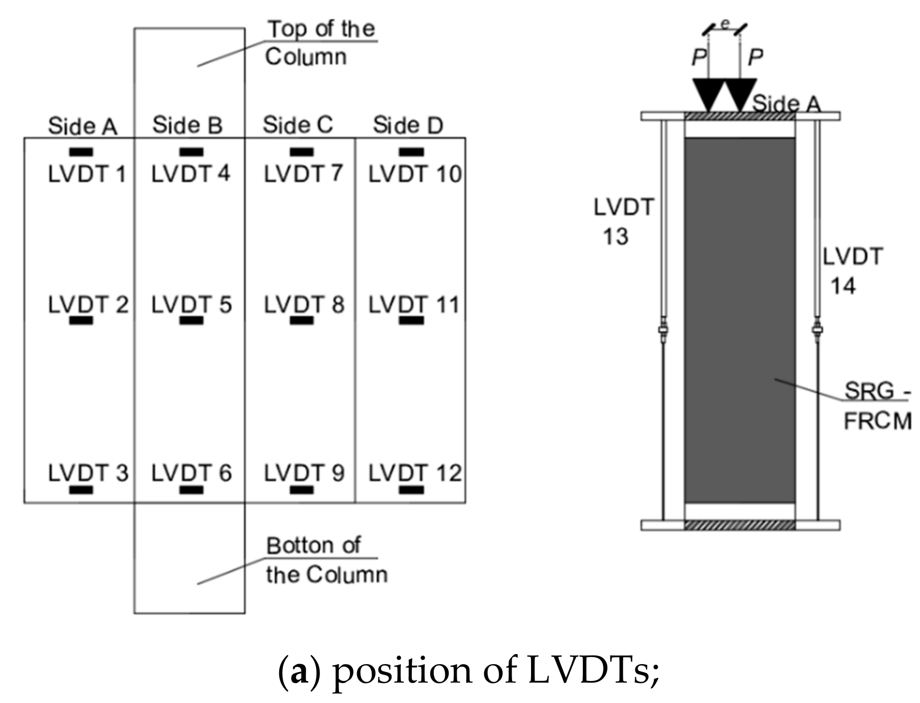
As shown in Figure 7, four vertical LVDTs (LVDTs 13–16) were attached to the inner part of the steel plate in order to measure the axial displacement while twelve LVDTs were positioned in the horizontal direction (four at the top (LVDTs 1, 4, 7, and 10), four at the mid-height (LVDTs 2, 5, 8, and 11) and four at the bottom (LVDTs 3, 6, 9 and 12) of the columns) to measure lateral displacements.
3. Results and Discussion
Results of tests relevant to this paper are reported and discussed in the following.
3.1. Failure Modes
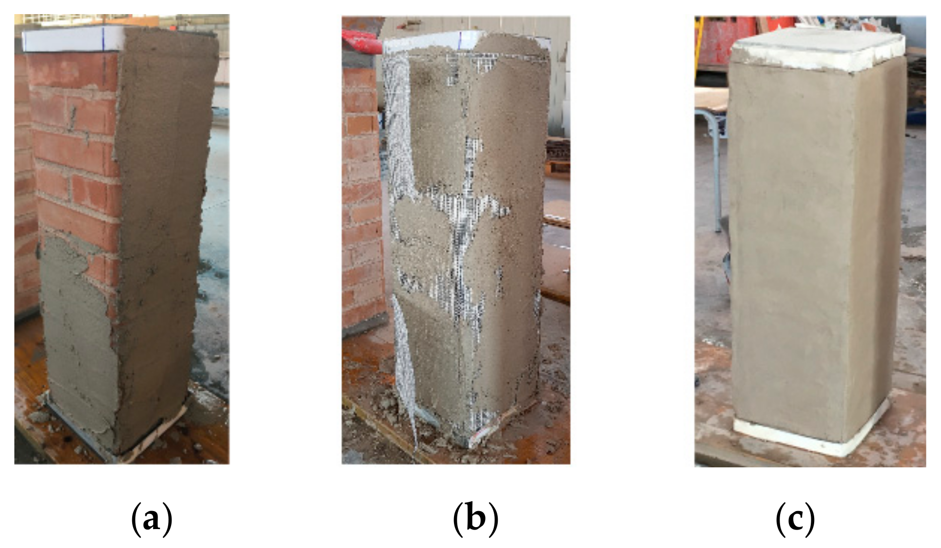
The failure configurations of tested specimens were illustrated in Figure 8, Figure 9 and Figure 10 to which the four faces of each specimen (Side A, Side B, Side C and Side D as indicated in Figure 7) have been reported. Failures occurred by crushing of the masonry, detachment of the external layer of the FRCM/matrix, slippage between fibers and grid and knife effect i.e., fiber break at the corner of the specimens.
Unconfined specimens failed by crushing of the masonry after the formation of a wide vertical crack at the middle-height of the specimens.
Confined specimens showed failure modes dependent on both the confining system and the confinement ratio. The failure configurations of tested confined columns were illustrated in Figure 8, Figure 9 and Figure 10.
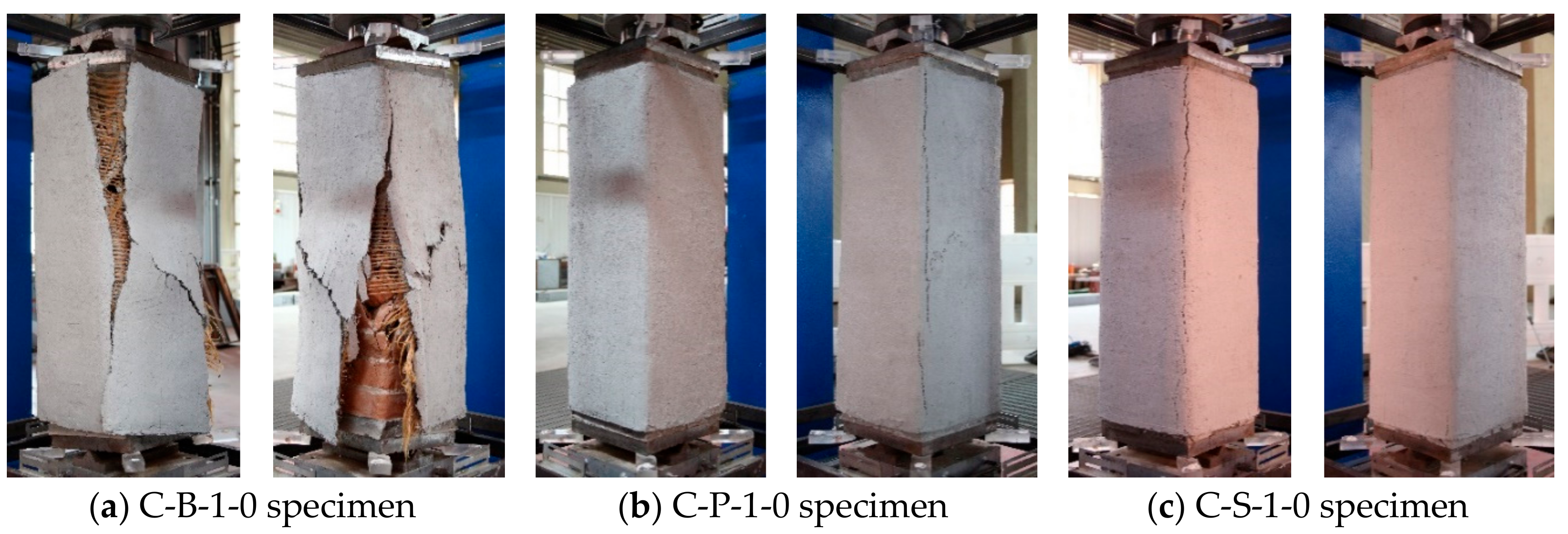
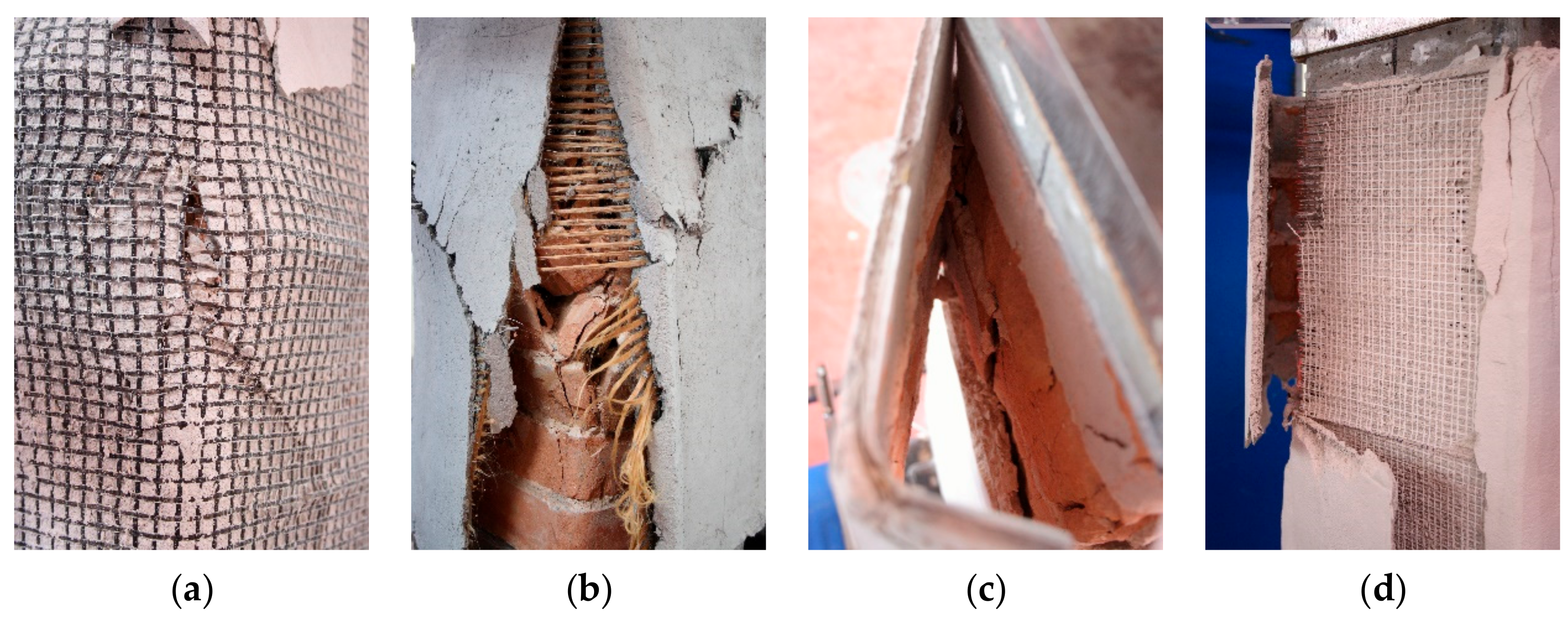
The failure configurations of columns wrapped with 1-layer of FRCM jacket are illustrated in Figure 8. It is evident that the column failure was different for each FRCM confining system. In particular, the failure of specimen C-B-1-0 was due to a knife effect associated with a rupture of the basalt grid at the mid-height (Figure 11a); at failure, the external layer of the matrix was completely destroyed. A relevant knife effect at the corner was observed in specimens C-P-1-0; the break of the PBO fibers was observed in correspondence of corners of the columns where relevant wide vertical cracks formed (Figure 11b).
The failure of SRG specimens was due to the detachment of the steel fabric segments in the overlap zones. The failure configurations of the C-S-1-1 and C-S-1-2 specimens are illustrated in Figure 11c,d; in the former specimen, the SRG jacket was detached from the masonry while in the latter one the external layer of the matrix was detached from the steel grid.
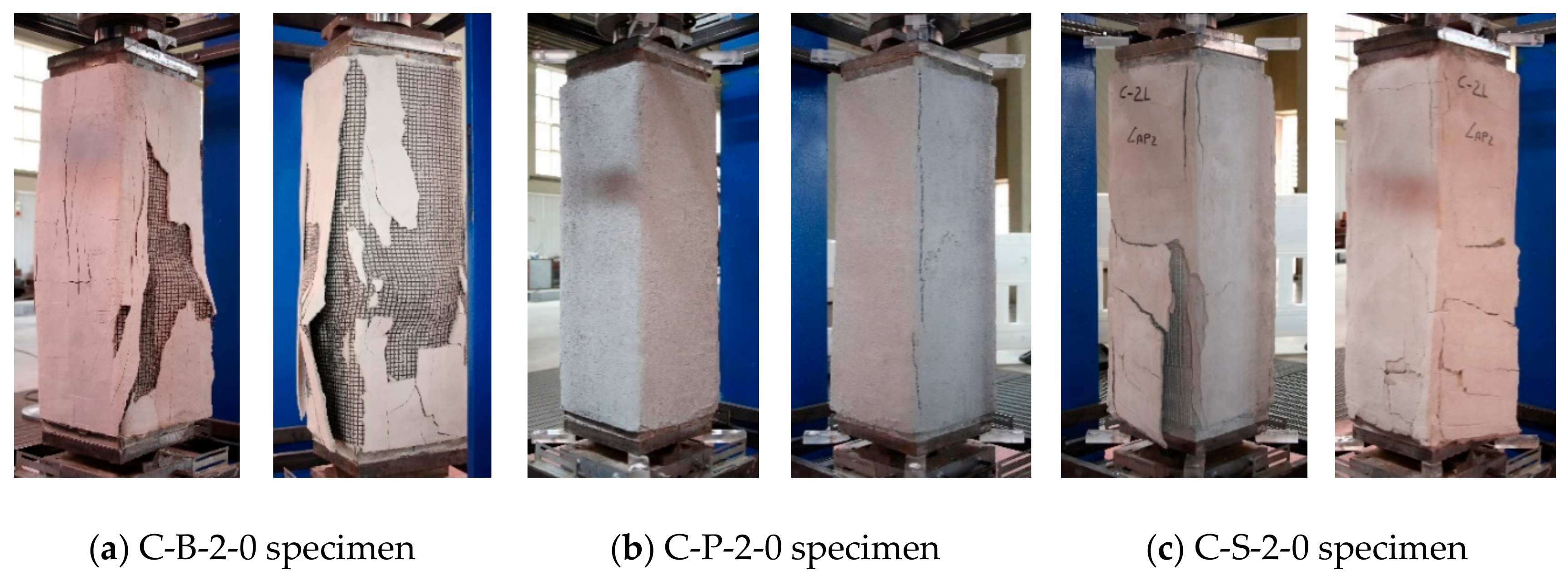
The failure configurations of the masonry columns confined with two FRCM layers are illustrated in Figure 9. The C-B-2-0 specimen failed similarly to the C-B-1-0 specimen: the external matrix was destroyed and the fibers break at the corners and along the height of the column. The C-P-2-0 specimen failed by the detachment of the confining jacket from the masonry (Figure 12a) associated with significant fiber/matrix slippages. The failure of the C-S-2-0 specimen was caused by the detachment of the external segment of the steel fabric; a break of the steel fibers was also observed at the corners. The detachment occurred at the interface steel fabric-to-mortar after the knife effect; it was related to the high density of fibers that avoided a complete penetration of the mortar between the cords of the steel fabrics.
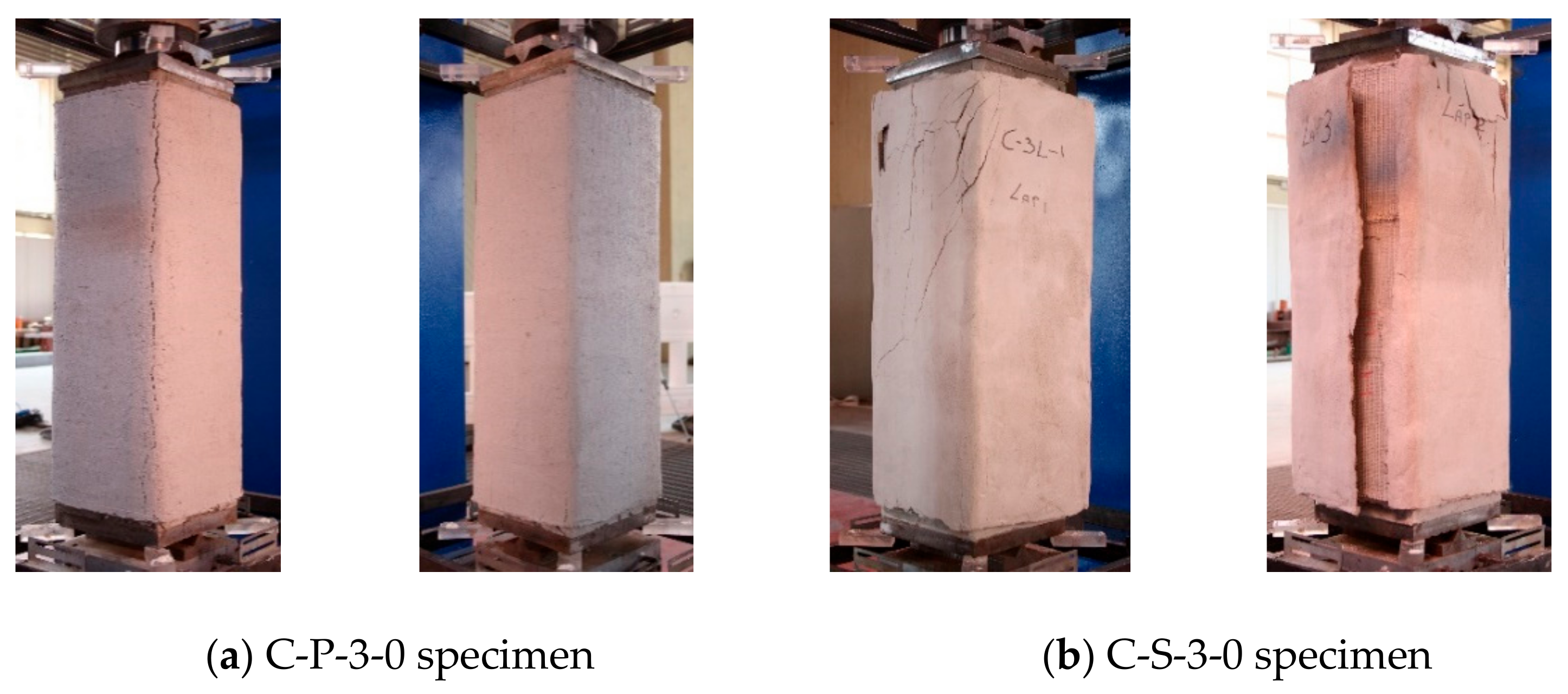
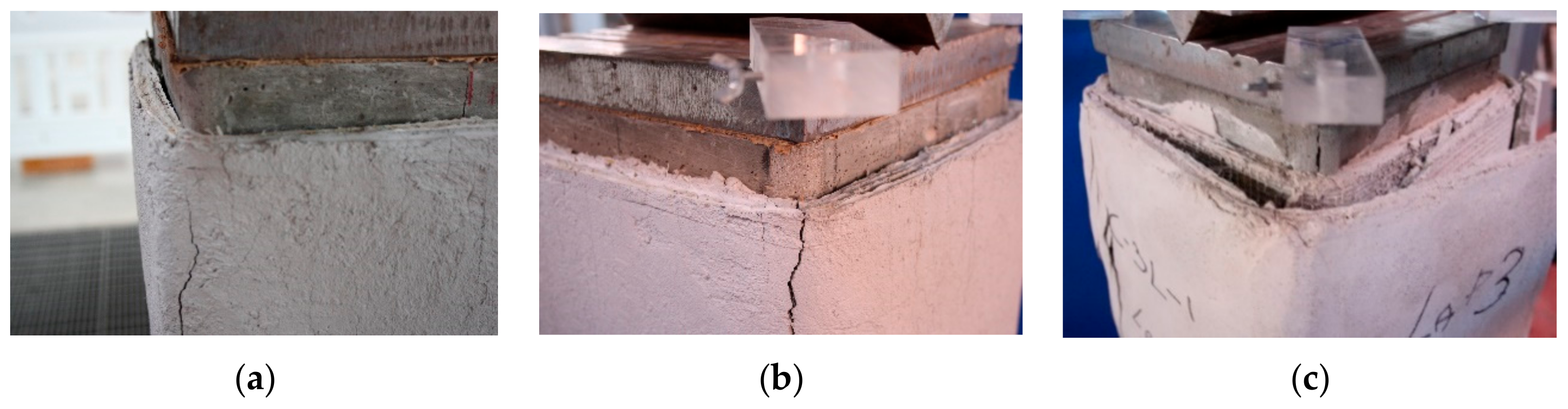
Figure 10 illustrates the failure configurations of the columns confined with three FRCM layers. The failure of the C-P-3-0 specimen, confined with three layers of PBO fabric, was due to the detachment of the jacket from the masonry substrate (Figure 12b); relevant fiber/matrix slippages were also observed mainly in correspondence of the overlap zone. A complete detachment of the external layer associated was observed at the failure of the C-S-3-0 specimen. The detachment developed along the whole height of the masonry column.
3.2. Peak Loads
Table 5 reports peak load values for all tested specimens. Obtained results allow evidencing that the confinement ratio in terms of peak load values ξ = Pcc /Pc0 being Pcc the peak load of the confined columns and Pc0 the average peak load value measured on unconfined specimens (Pc0 = 329.36 kN), is influenced by the number of confining layers.
For specimens confined with PBO fabrics, ξ is varying between 2.01 and 2.89 and it is increasing with the number of confining layers. The same trend was observed for columns confined with SRG where the confinement ratio was 1.48 for the one SRG layer confined specimen, 1.95 and 2.87 for two and three SRG layers confined specimens, respectively.
Specimen C-B-1-0 confined with one layer of basalt fabric reached a peak load coincident to that of the specimen C-S-1-1 confined with one SRG layer. Specimen C-B-2-0, confined with two layers of basalt fabrics, failed under a peak load lesser than specimen C-B-1-0 confined with one layer of basalt fabrics; this was due, probably, to a local effect as evidenced in the analysis of the failure modes.
By comparing the peak load values of C-S-1-0-1 and C-S-1-0-2 specimens, both confined with one 1-SRG layer, it is possible to evidence the influence of the overlap configuration on the peak load. The peak load of the C-S-1-0-2 specimen was, in fact, 42% higher than that of the C-S-1-0-1 specimen.
The analysis of results evidenced that peak load values of C-S-1-25 and C-S-1-50 columns are almost coincident with each other; the recorded values were, in fact, 424.09 kN and 415.02 kN for the C-S-1-25 and C-S-1-50 specimens, respectively. The peak loads of the eccentrically loaded columns were lesser than those of the concentrically loaded columns confined with the same amount of SRG layers. The average decrease in the peak load of the C-S-1-25 and C-S-1-50 specimens was, in fact, 13% and 39% of the peak load values of C-S-1-0-2 and C-S-1-0-1 specimens, respectively.
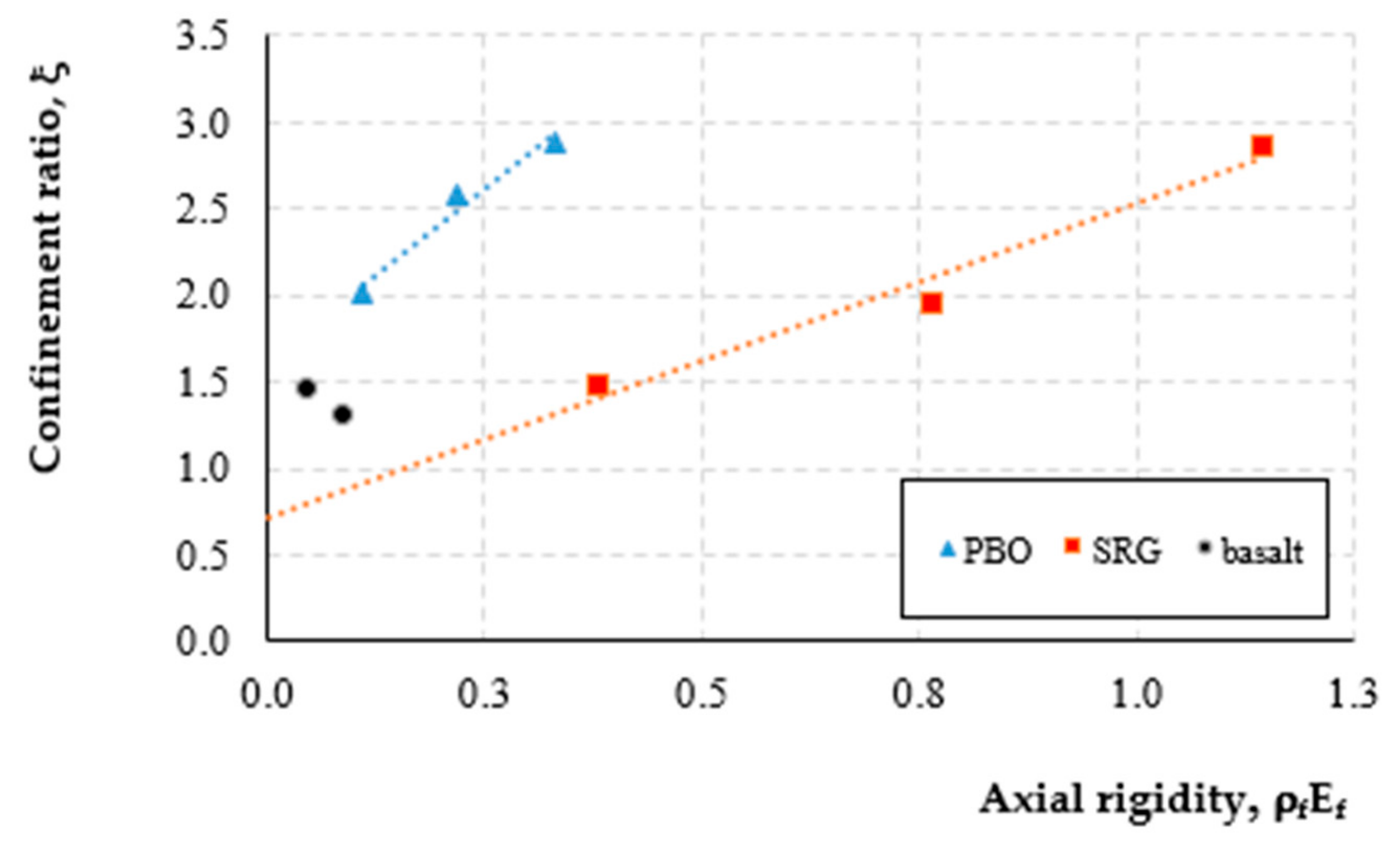
In Table 5 values of the reinforcement ratio of specimens ρf = 4 nf t/D and the axial rigidity of the composite ρf Ef being nf the number of confining layers, t the equivalent thickness of the fabrics, Ef the elastic modulus of the fibers and, D the length of the diagonal of the cross-section of specimens, are also reported. These two parameters allow giving evidence on the effectiveness for each FRCM system on the confinement of masonry columns: as well-known they are associated with the lateral confining pressure exerted by the confining system [14]. From the analysis of the results, emerge that the reinforcement ratio and the axial rigidity of the SRG system are higher than those of PBO and basalt-FRCM systems. In addition, the confinement ratio increases linearly for both PBO-FRCM and SRG while it decreases for basalt-FRCM. Figure 13 reports the relationship between the confinement ratio, ξ and the axial rigidity, ρf Ef, for the three considered confining systems; in the same figure the trend lines ξ-ρf Ef for PBO-FRCM and SRG systems are drawn.
With reference to the specimens confined with the same configuration i.e., the same overlap position along the height (all PBO columns and C-S-1-0-1, C-S-2-0 and C-S-3-0 columns), the two trend-lines are expressed as: ξ = 4 ρf Εf + 1.61 for the PBO FRCM system and, ξ = 1.82 ρf Ef + 0.71 for the SRG system.
A simple comparison between the two relationships evidences that the slope of the trend-line of the PBO-FRCM confined columns is greater than that of the SRG confined columns. As a consequence, the PBO FRCM system is more effective than the SRG system. By the above equations, for the same value of the axial rigidity, the peak load of PBO-FRCM confined columns results in 2.25 times greater than the SRG confined columns while it is in average 1.4 times the value obtained for basalt-FRCM confined specimens.
Similarly, for the same value of the axial rigidity, the peak load of SRG confined columns is lesser than that measured on basalt-FRCM columns: 0.5 and 0.67 times for 1-layer and 2-layers confined columns, respectively.
3.3. Strain Values and Ductility
In Table 5 values of the axial strains corresponding to the peak loads (εcc) and those of the ultimate strain (εu) corresponding to the failure of the specimens are, also, reported. This last value was evaluated as a conventional value corresponding to the 95% of the peak strength on the descending branch of the stress–strain curves.
Values of εu and εcc are used to calculate the ductility values of each confined specimen as the ratio δ = εu/εcc. Obtained results, listed in the last column in Table 5, puts in evidence that the best results are those corresponding to the basalt-FRCM confined specimens. The comparison between the ductility values obtained for SRG and basalt-FRCM confined specimens (both confining systems use the same inorganic mortar), shows that the latter are more ductile than the former for each value of the reinforcement ratio. This is related to the rigidity, Eftf, of the basalt-FRCM confining system which is lesser than that of the SRG system.
3.4. Stress-Strain Curves
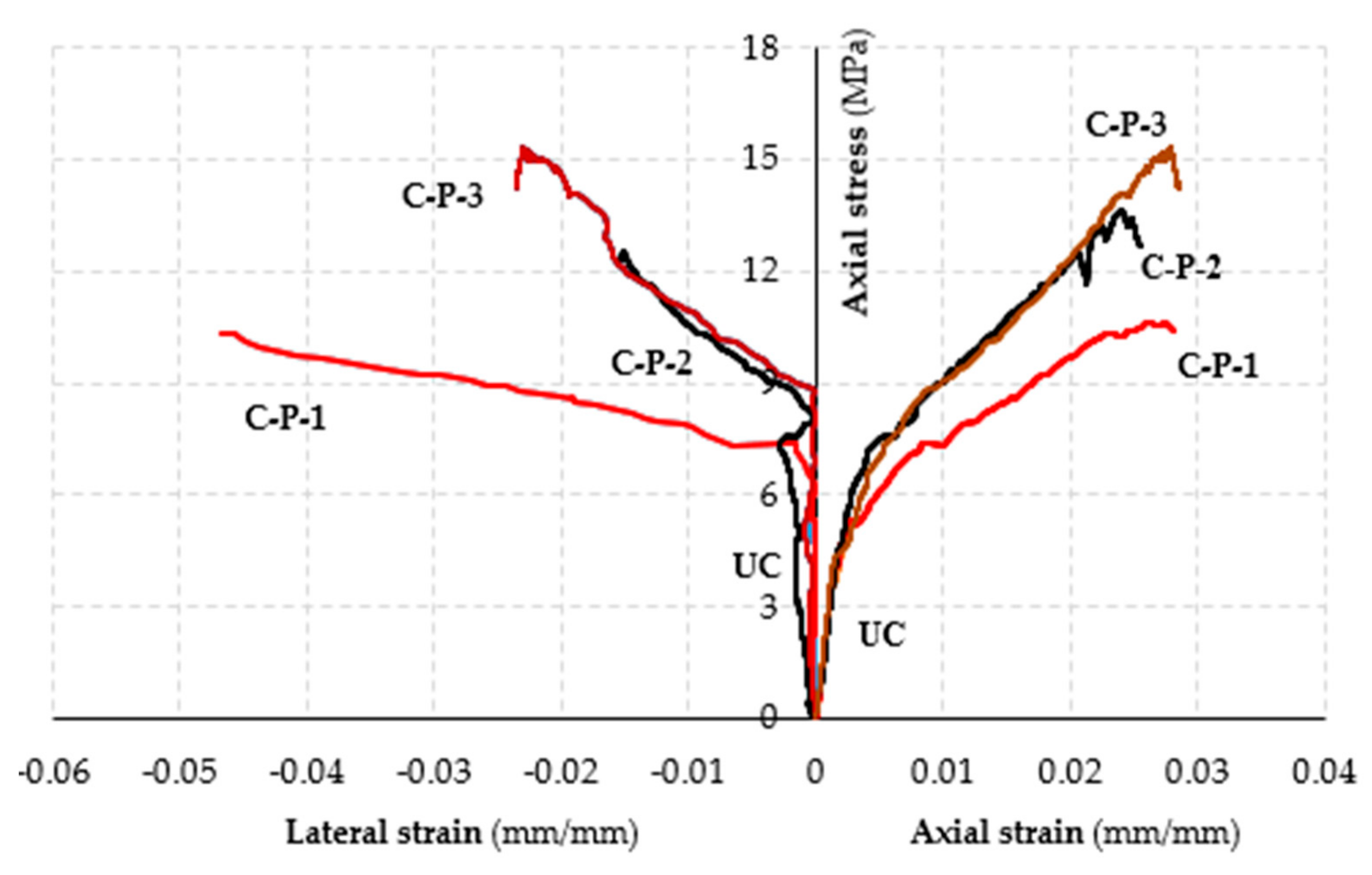
The axial stress-axial and lateral strain curves determined through tests on masonry columns subjected to concentric axial loads, are illustrated in Figure 14, Figure 15 and Figure 16 for all tested specimens.
Strains values were determined through displacement values measured during tests by LVDTs; in Figure 14, Figure 15 and Figure 16 the average values of strains recorded at the mid-height of the columns, are reported.
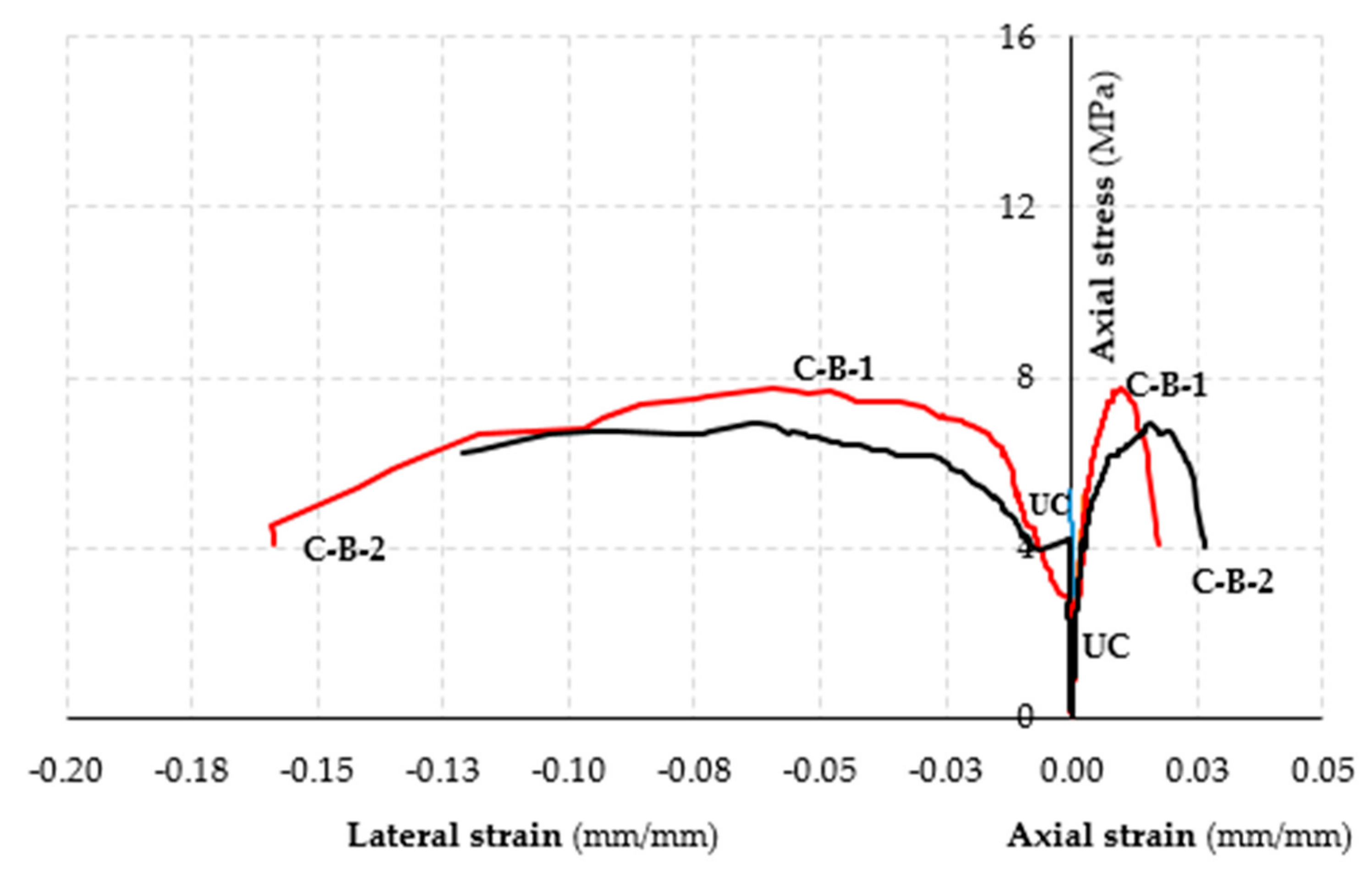
The analysis of curves provides evidence that each curve presents three different branches. An initial linear branch associated with the elastic behavior is succeeded by a nonlinear ascending branch until the peak load; a third nonlinear branch describes the post peak behavior of the confined specimens. For specimens PBO-FRCM and SRG confined columns the extension of the post-peak branch is very limited giving evidence to a sudden and brittle failure of the confined specimens; for basalt-FRCM confined specimens, on the contrary, the post-peak behavior is described by a descending soft curve.
High lateral displacement values were measured in both columns confined with basalt fibers; similar results were obtained for 3-layer confined columns with both PBO and steel fibers. Conversely, lateral displacements measured in 1-layer and 2-layer columns confined with PBO-FRCM and SRG were similar to those measured in un-confined columns.
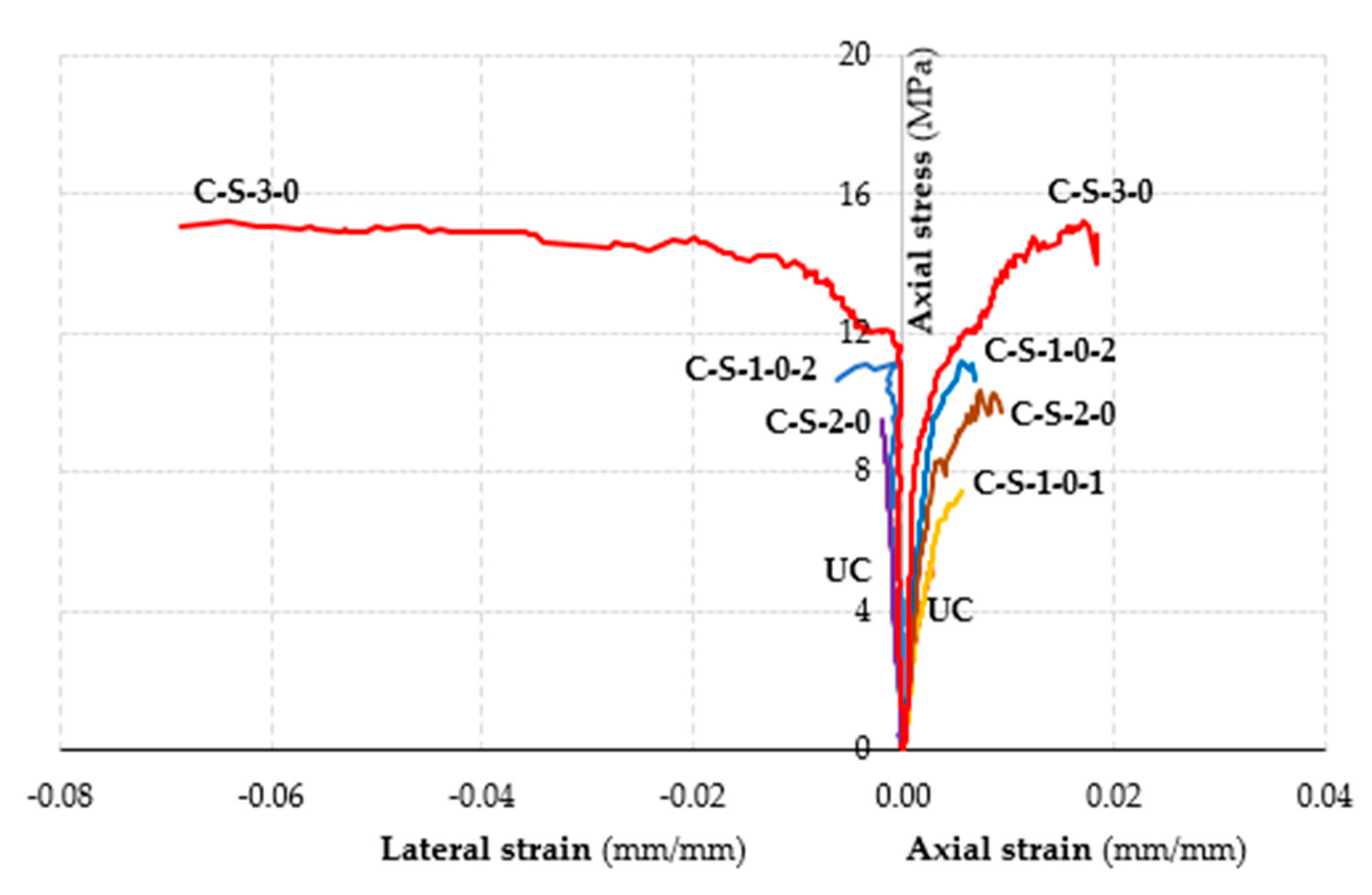
In addition, the comparison between curves relative to the C-S-1-0-1 and C-S-1-0-2 specimens allows evidencing of the overlap configuration impact on the response of specimens concerning both load and displacement values. The curve of the C-S-1-0-1 specimen is, in fact, almost coincidental with that of the un-confined specimen while the curve of the C-S-1-0-2 specimen presents a more rigid first branch than those of C-S-1-0-1 and C-S-0-2 specimens.
In Figure 17 axial stress-axial and lateral strains evaluated by displacements measured on SRG confined columns subjected to eccentric load are reported. Both curves are compared with the corresponding un-confined column. Curves relative to C-S-1-25 and C-S-1-50 specimens are very similar confirming that the structural response of confined specimens is not influenced by the eccentricity value.
4. Experimental-Theoretical Comparison
Few models to predict the strength of FRCM confined masonry columns are, actually, available in the literature. Among those the design-oriented- model of Cascardi et al. [26] developed by a multiple linear regression approach in which the strength of the mortar and the elastic modulus of the fibers are the main parameters. A simplified version of the general model, easier to use for practical applications, also proposed by Cascardi et al. [26], is expressed by the following general expression:
being fmc and fm0, the compression strength of the confined and un-confined columns, respectively, fl,eff the effective confining pressure expressed as a function of the maximum confinement pressure fl,
In Equations (3) and (4), nf is the number of FRCM layers, tf is the thickness of the fiber mesh (mm), b and h are the length (mm) and the width (mm) of the cross section of the column, D is the diagonal length of the cross-section (mm), r is the radius of the rounding corner of the column cross-section (mm). The tensile strain, εf, is the ultimate tensile strain of the fiber mesh of the FRCM system, εfu.
In Equation (1) the coefficient k is expressed as
where fmat is the compressive strength of the FRCM-matrix (MPa) while ρmat is the geometrical percentage of matrix in the FRCM system expressed as
where tmat is the total thickness of the FRCM-matrix (mm).
A similar model was, recently proposed in the Italian guidelines DT 215 [29] where some different relationships are used. In the DT 215 model the coefficient k (Equation (1)) is expressed as k = (gm/1000) being gm the masonry mass density in units of kg/m3 (approximately 1800 kg/m3 for the specimens in this study), while the tensile strain of fibers is expressed as
being ηa and γm environmental and partial safety factors (taken as 1.0 in this study).
Both models are used for a comparison between their predictions and experimental results; obtained results are reported in Table 6.
The analysis of obtained results evidences that predictions of the model proposed by Cascardi et al. are more accurate than those of the DT 215 model. This is an expected result because the latter model being consistent with a guideline which is still based on a limited number of test results, furnishes more conservative predictions. The Cascardi et al. model furnishes good predictions for 1-layer FRCM confined specimens while it overestimates the peak strength of 2-layer and 3-layer FRCM confined specimens. In particular, the model furnishes less accurate predictions for PBO-FRCM confined specimens. The model overestimates the contribution of the mortar strength and, consequently, it becomes relevant when, as in specimens confined with PBO-FRCM, high strength mortar embedded high strength fibers is used. More accurate calibration of parameters through the analysis of a consistent amount of experimental results, is, then, required to improve the model.
5. Conclusions
The paper described and discussed the results of an investigation carried out on the performances of clay brick masonry prismatic columns confined with different FRCM systems tested by axial compression loads. The investigation was performed considering as variable parameters the type of fibers (PBO, steel and basalt), the confinement ratio (one, two and three confining layers), the eccentricity of compression loads, the confining configuration, and the type of mortar. The obtained results allow drawing the following conclusions:
The structural response of the confined masonry columns was improved both as for strength and ductility with regards to the un-confined ones; it increased with the number of confining layers and was not influenced by the load eccentricity. The best performances, mainly in terms of peak load values were furnished by PBO-FRCM confined specimens (FRCM system made with high strength fibers combined with high strength mortar);
- Columns confined with SRG and basalt FRCM are more ductile than those confined with PBO FRCM;
- The failure mode of the SRG confined columns was influenced by the confining configuration; an accurate configuration of the overlapping zones sensibly improves the performances of the SRG confined columns;
- Very large lateral displacements were recorded at the failure of the columns confined with basalt FRCM jackets (i.e., a confining system made with low strength fibers embedded into medium strength mortar);
- The Cascardi et al. model, adopted to make a prediction of the peak strength of the confined masonry columns furnished good predictions for one layer confined specimens while it overestimates the response of the 2-layer and 3-layer FRCM confined columns. The model is too sensitive to the compression strength of the mortar and it seems to underestimate the capability of masonry columns confined with FRCM systems made with high strength fibers and high strength mortar as the PBO FRCM system.
However, the results of tests described and discussed in the paper require further experimental investigations to confirm their validity; they can be useful to give a contribution to construct an experimental database essential for the definition of reliable prediction models.
Author Contributions
The Authors contributed equally to the conception or design of the work and the acquisition, analysis, and interpretation of data for the work. The Authors drafted the work revising it critically for important intellectual content, provided approval for publication of the content, and agreed to be accountable for all aspects of the work in ensuring that questions related to the accuracy or integrity of any part of the work are appropriately investigated and resolved. All authors have read and agreed to the published version of the manuscript.
Funding
This research received no external funding.
Conflicts of Interest
The Authors declare that the research was conducted in the absence of any commercial or financial relationships that could be construed as a potential conflict of interest.
References
- Nanni, A. FRCM strengthening: a new tool for concrete and masonry repair. Concr. Int. 2012, 34, 43–49. [Google Scholar]
- Carloni, C.; Bournas, D.A.; Carrozzi, G.C.; D’Antino, T.; Fava, G.; Focacci, F.; Giacomin, G.; Mantegazza, G.; Pellegrino, C.; Perinelli, C.; et al. Fiber Reinforced Composites with Cementitious (Inorganic) Matrix, Chapter 9; Springer: Berlin, Germany, 2015; pp. 349–391. ISBN 978-94-017-7335-5. [Google Scholar]
- Iorfida, A.; Verre, S.; Candamano, S.; Ombres, L. Tensile and direct shear responses of basalt-fibre reinforced mortar based materials. In International Conference on Strain-Hardening Cement-Based Composites; Metcherine, V., Slowik, V., Kabele, V., Eds.; Springer: Dordrecht, The Netherlands, 2017; pp. 544–552. [Google Scholar] [CrossRef]
- Papanicolaou, C.G.; Triantafillou, T.C.; Karlos, K.; Papathanasiou, M. Textile reinforced mortar (TRM) versus FRP as strengthening material of UMR walls: In plane cyclic loading. Mater. Struct. 2007, 40, 1081–1097. [Google Scholar] [CrossRef]
- Papanicolaou, C.G.; Triantafillou, T.C.; Karlos, K.; Papathanasiou, M. Textile reinforced mortar (TRM) versus FRP as strengthening material of UMR walls: Out of plane cyclic loading. Mater. Struct. 2008, 41, 143–157. [Google Scholar] [CrossRef]
- Babaeidarabad, S.; Arboleda, D.; Loreto, G.; Nanni, A. Shear strengthening of unreinforced concrete masonry walls with fabric reinforced cementitious matrix. Constr. Build. Mater. 2014, 65, 243–253. [Google Scholar] [CrossRef]
- De Felice, G.; De Santis, S.; Garmendia, L.; Ghiassi, B.; Larrinaga, P.; Lourenço, P.B.; Oliveira, D.V.; Paolacci, F.; Papanicolaou, C.G. Mortar-based systems for externally bonded strengthening of masonry. Mater. Struct. 2014, 47, 2021–2037. [Google Scholar] [CrossRef]
- Mezrea, P.; Yilmaz, I.; Ispir, M.; Binbir, E.; Bal, I.; Ilki, A. External jacketing of unreinforced historical masonry piers with open-grid basalt-reinforced mortar. J. Compos. Constr. 2016, 21, 04016110. [Google Scholar] [CrossRef]
- De Santis, S.; Roscini, F.; de Felice, G. Retrofitting Masonry Vaults with Basalt Textile Reinforced Mortar. Key Eng. Mater. 2017, 747, 250–257. [Google Scholar] [CrossRef]
- Ombres, L. Flexural analysis of reinforced concrete beams strengthened with a cement based high strength composite material. Compos. Struct. 2011, 94, 143–155. [Google Scholar] [CrossRef]
- Tetta, Z.C.; Koutas, L.N.; Bournas, D.A. Shear strengthening of full-scale RC T beams using textile-reinforced mortar and textile-based anchors. Compos. Part B Eng. 2016, 95, 225–239. [Google Scholar] [CrossRef]
- Ombres, L. Structural performances of reinforced concrete beams strengthened in shear with a cement based fiber composite material. Compos. Struct. 2015, 122, 316–329. [Google Scholar] [CrossRef]
- Sneed, L.H.; Verre, S.; Carloni, C.; Ombres, L. Flexural behavior of RC beams strengthened with steel-FRCM composite. Eng. Struct. 2016, 127, 686–699. [Google Scholar] [CrossRef]
- Ombres, L. Concrete confinement with a cement based high strength composite material. Compos. Struct. 2014, 109, 294–304. [Google Scholar] [CrossRef]
- Ombres, L. Confinement effectiveness in eccentrically loaded masonry columns strengthened by fiber reinforced cementitious matrix (FRCM) jackets. Key Eng. Mater. 2015, 624, 551–558. [Google Scholar] [CrossRef]
- Kreivakais, T. Experimental study on carbon fiber textile reinforced mortar system as a means for confinement of masonry columns. Constr. Build. Mater. 2019, 208, 723–733. [Google Scholar] [CrossRef]
- Fossetti, M.; Minafò, G. Comparative experimental analysis on the compressive behaviour of masonry columns strengthened by FRP, BFRCM or steel wires. Compos. Part B Eng. 2017, 112, 112–124. [Google Scholar] [CrossRef]
- Maddaloni, G.; Cascardi, A.; Balsamo, A.; Di Ludovico, M.; Micelli, F.; Aiello, M.A.; Prota, A. Confinement of Full-Scale Masonry Columns with FRCM Systems. Key Eng. Mater. 2017, 747, 374–381. [Google Scholar] [CrossRef]
- Santandrea, M.; Quartarone, G.; Carloni, C.; Gu, X. Confinement of masonry columns with steel and basalt FRCM composites. Key Eng. Mater. 2017, 747, 342–349. [Google Scholar] [CrossRef]
- Carloni, C.; Mazzotti, C.; Savoia, M.; Subramaniam, K.V. Confinement of masonry columns with FRCM composites. Key Eng. Mater. 2015, 624, 644–651. [Google Scholar] [CrossRef]
- Cascardi, A.; Micelli, F.; Aiello, M.A. FRCM-confined masonry columns: Experimental investigation on the effect of the inorganic matrix properties. Constr. Build. Mater. 2018, 186, 811–825. [Google Scholar] [CrossRef]
- Minafò, G.; La Mendola, L. Experimental investigation on the effect of mortar grade on the compressive behaviour of FRCM confined masonry columns. Compos. Part B Eng. 2018, 146, 1–12. [Google Scholar] [CrossRef]
- Ombres, L.; Verre, S. Masonry columns strengthened with Steel Fabric Reinforced Cementitious Matrix (S-FRCM) jackets: Experimental and numerical analysis. Measurement 2018, 127, 238–245. [Google Scholar] [CrossRef]
- Sneed, L.H.; Carloni, C.; Baietti, G.; Fraioli, G. Confinement of clay masonry columns with SRG. Key Eng. Mater. 2017, 747, 350–357. [Google Scholar] [CrossRef]
- de Felice, G.; Nanni, A. (chairs). Guide to design and construction of externally bonded Fabric-Reinforced Mortar (FRM) systems for repair and strengthening masonry structures (Draft document), 2018.
- Cascardi, A.; Longo, F.; Micelli, F.; Aiello, M.A. Compressive strength of confined column with fiber reinforced mortar (FRM): New design-oriented models. Constr. Build. Mater. 2017, 156, 387–401. [Google Scholar] [CrossRef]
- Krevaikas, T.D.; Triantafillou, T.C. Masonry confinement with fibre-reinforced polymers. J. Compos. Constr. 2005, 9, 128–135. [Google Scholar] [CrossRef]
- Di Ludovico, M.; D’Ambra, C.; Prota, A.; Manfredi, G. FRP Confinement of tuff and clay brick columns: Experimental study and assessment of analytical models. J. Compos. Constr. 2010, 14, 583–596. [Google Scholar] [CrossRef]
- CNR (Italian Council of Research). Istruzioni per la Progettazione, L’esecuzione ed il Collaudo di Interventi di Consolidamento Statico Mediante L’utilizzo di Compositi Fibrorinfozati a Matrice Inorganica; 215 CNR-DT; CNR (Italian Council of Research): Rome, Italy, 2018. [Google Scholar]
- CEN (European Committee for Standardization). Methods of Test for Masonry Unit—Part 1: Determination of Compressive Strength; EN 772-1; CEN (European Committee for Standardization): Brussel, Belgium, 2002. [Google Scholar]
- UNI. UNI EN 12190:2000. Product and system for the protection and repair concrete structures—Test methods—Determination of compressive strength of repair mortar; UNI: Rome, Italy, 2000. [Google Scholar]
- UNI. EN 1015-11. Methods of test for mortar for masonry Part 11: Determination of flexural and compressive strength of hardened mortar 2006; UNI: Rome, Italy, 2006. [Google Scholar]
Figure 1.
Geometry of the masonry columns. (a) Scheme of the column; (b) un-confined columns.

Figure 2.
FRCM textiles: (a) SRG, (b) PBO and (c) basalt (dimensions are in mm).

Figure 3.
Test setup: (a) PBO and (b) Steel, Basalt bare textiles.

Figure 4.
Tensile tests of dry textile: stress-strain curves.


Figure 5.
Confinement steps: (a) application of the first mortar layer, (b) sheet/fabric mesh installation and (c) application of the external mortar layer.
Figure 5.
Confinement steps: (a) application of the first mortar layer, (b) sheet/fabric mesh installation and (c) application of the external mortar layer.

Figure 6.
Overlap configuration (a,b) and, (c) position of the steel fabric segments along the height for specimens confined with one and three SRG layers and, (d) two SRG layers. (The dimensions are in mm).
Figure 6.
Overlap configuration (a,b) and, (c) position of the steel fabric segments along the height for specimens confined with one and three SRG layers and, (d) two SRG layers. (The dimensions are in mm).

Figure 7.
Test set up.


Figure 8.
Failure configurations of one layer confined columns.

Figure 9.
Failure configurations of two layer confined columns.

Figure 10.
Failure configurations of three layer confined columns.

Figure 11.
Details of the specimen’s failure: knife effect in (a) C-B-1-0; (b) C-P-1-0 specimens; (c) detachment in the C-S-1-1 specimen; and (d) detachment and fiber rupture in the C-S-1-2 specimen.
Figure 11.
Details of the specimen’s failure: knife effect in (a) C-B-1-0; (b) C-P-1-0 specimens; (c) detachment in the C-S-1-1 specimen; and (d) detachment and fiber rupture in the C-S-1-2 specimen.

Figure 12.
Details of the specimen’s failure: (a) detachment in the C-P-2-0 specimen; (b) detachment in the C-P-3-0 specimen; (c) detachment of the steel grid in the C-S-3-0 specimen.
Figure 12.
Details of the specimen’s failure: (a) detachment in the C-P-2-0 specimen; (b) detachment in the C-P-3-0 specimen; (c) detachment of the steel grid in the C-S-3-0 specimen.

Figure 13.
Confinement ratio versus axial rigidity for confined columns.

Figure 14.
Axial stress-strain curves for PBO-FRCM confined columns.

Figure 15.
Axial stress -strain curves for basalt-FRCM confined columns.

Figure 16.
Axial stress -strain curves for SRG confined columns.

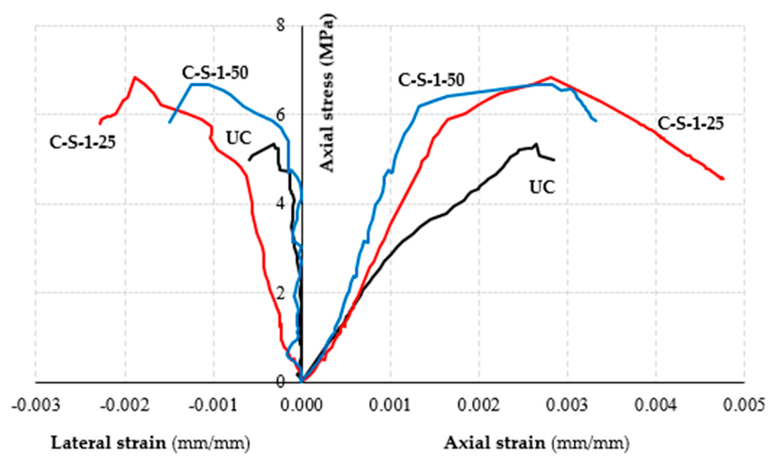
Figure 17.
Axial stress-strain curves for eccentrically loaded SRG confined columns.


Table 1.
Details of tested specimens.
| Specimen | No of Confining Layers | Type of Fiber | Eccentricity Values (mm) |
|---|---|---|---|
| UC1 | - | - | 0.0 |
| UC2 | - | - | 0.0 |
| C-P-1-0 | 1 | PBO | 0.0 |
| C-P-2-0 | 2 | PBO | 0.0 |
| C-P-3-0 | 3 | PBO | 0.0 |
| C-S-1-0-1 | 1 | SRG | 0.0 |
| C-S-1-0-2 | 1 | SRG | 0.0 |
| C-S-2-0 | 2 | SRG | 0.0 |
| C-S-3-0 | 3 | SRG | 0.0 |
| C-S-1-25 | 1 | SRG | 25.0 |
| C-S-1-50 | 1 | SRG | 50.0 |
| C-B-1-0 | 1 | Basalt | 0.0 |
| C-B-2-0 | 2 | Basalt | 0.0 |
Table 2.
Mechanical properties of the steel, basalt and PBO fibers.
| Fibers | Elastic Modulus (GPa) (CoV) | Tensile Stress (GPa) (CoV) | Ultimate Strain (mm/mm) (CoV) |
|---|---|---|---|
| Steel 1200 | 199.9 (0.081) | 3.00 (0.010) | 0.019 (0.072) |
| Basalt B400 | 60.7 (0.018) | 0.98 (0.022) | 0.018 (0.039) |
| PBO | 211.4 (0.041) | 3.40 (0.031) | 0.025 (0.080) |
Table 3.
Mechanical properties of the matrix.
| Type of Mortar | Compressive Strength (MPa) (CoV) | Flexural Tensile Strength (MPa) (CoV) |
|---|---|---|
| Mineral NHL-mortar | 12.85 (0.15) | 2.65 (0.05) |
| Pozzolana mortar | 36.16 (0.04) | 5.50 (0.14) |
Table 4.
Mechanical properties of FRCM systems.
| Composite System | Elastic Cracked Modulus (GPa) (CoV) | Tensile Strength (MPa) (CoV) | Ultimate Strain (mm/mm) (CoV) |
|---|---|---|---|
| SRG | 141 (0.110) | 1203 (0.290) | 0.019 (0.015) |
| Basalt FRCM | 37 (0.091) | 434 (0.121) | 0.020 (0.035) |
| PBO-FRCM | 94 (0.090) | 1589 (0.170) | 0.0125 (0.020) |
Table 5.
Test results.
| Specimen | Peak Load (kN) | Confinement Ratio, ξ | Peak Axial Strain, εcc (mm/mm) | Ultimate Strain, εu (mm/mm) | Ductility |
|---|---|---|---|---|---|
| UC1 | 324.27 | - | 0.0025 | 0.0027 | 1.00 |
| UC2 | 334.44 | - | 0.0026 | 0.0028 | 1.00 |
| C-P-1-0 | 661.88 | 2.01 | 0.0263 | 0.0281 | 1.07 |
| C-P-2-0 | 849.76 | 2.58 | 0.0259 | 0.0273 | 1.05 |
| C-P-3-0 | 951.88 | 2.89 | 0.0279 | 0.0286 | 1.02 |
| C-S-1-0-1 | 692.66 | 2.10 | 0.0056 | 0.0069 | 1.23 |
| C-S-1-0-2 | 487.54 | 1.48 | 0.0076 | 0.0100 | 1.31 |
| C-S-2-0 | 642.69 | 1.95 | 0.0073 | 0.0093 | 1.27 |
| C-S-3-0 | 945.59 | 2.87 | 0.0170 | 0.0184 | 1.08 |
| C-S-1-25 | 424.09 | 1.29 | 0.0028 | 0.0037 | 1.32 |
| C-S-1-50 | 415.02 | 1.26 | 0.0028 | 0.0033 | 1.18 |
| C-B-1-0 | 481.36 | 1.46 | 0.0098 | 0.0173 | 1.76 |
| C-B-2-0 | 432.27 | 1.31 | 0.0158 | 0.0263 | 1.66 |
Table 6.
Model predictions/experimental comparison.
| Specimen | Confinement Ratio (Exp) | DT 215 Model | Pred/Exp | Cascardi et al. Model | Pred/Exp |
|---|---|---|---|---|---|
| C-P-1-0 | 2.01 | 1.266 | 0.630 | 2.033 | 1.011 |
| C-P-2-0 | 2.58 | 1.376 | 0.533 | 3.192 | 1.237 |
| C-P-3-0 | 2.89 | 1.461 | 0.505 | 4.579 | 1.584 |
| C-S-1-0-1 | 2.10 | 1.400 | 0.714 | 1.600 | 0.754 |
| C-S-1-0-2 | 1.48 | 1.400 | 1.013 | 1.600 | 1.081 |
| C-S-2-0 | 1.95 | 1.706 | 0.875 | 2.272 | 1.165 |
| C-S-3-0 | 2.87 | 1.864 | 0.650 | 3.078 | 1.072 |
| C-S-1-25 | 1.29 | 1.400 | 1.163 | 1.600 | 1.240 |
| C-S-1-50 | 1.26 | 1.400 | 1.111 | 1.600 | 1.270 |
| C-B-1-0 | 1.46 | 1.133 | 0.776 | 1.198 | 0.820 |
| C-B-2-0 | 1.31 | 1.239 | 0.820 | 1.420 | 1.084 |
| Average | 1.92 | 1.42 | 0.78 | 2.19 | 1.12 |
| (CoV) | 0.32 | 0.14 | 0.26 | 0.46 | 0.20 |
© 2020 by the authors. Licensee MDPI, Basel, Switzerland. This article is an open access article distributed under the terms and conditions of the Creative Commons Attribution (CC BY) license (http://creativecommons.org/licenses/by/4.0/).
Share and Cite
MDPI and ACS Style
Ombres, L.; Verre, S. Analysis of the Behavior of FRCM Confined Clay Brick Masonry Columns. Fibers 2020, 8, 11. https://0-doi-org.brum.beds.ac.uk/10.3390/fib8020011
AMA Style
Ombres L, Verre S. Analysis of the Behavior of FRCM Confined Clay Brick Masonry Columns. Fibers. 2020; 8(2):11. https://0-doi-org.brum.beds.ac.uk/10.3390/fib8020011
Chicago/Turabian StyleOmbres, Luciano, and Salvatore Verre. 2020. "Analysis of the Behavior of FRCM Confined Clay Brick Masonry Columns" Fibers 8, no. 2: 11. https://0-doi-org.brum.beds.ac.uk/10.3390/fib8020011
Note that from the first issue of 2016, this journal uses article numbers instead of page numbers. See further details here.