Flexural Behavior of High Strength Self-Compacted Concrete Slabs Containing Treated and Untreated Geogrid Reinforcement


1
Civil Engineering Department, Faculty of Engineering, Sinai University, El Arish 45511, Egypt
2
Civil Engineering Department, Faculty of Engineering, Port Said University, Port Said 42511, Egypt
3
Civil Engineering Department, Faculty of Engineering, Beni-Suef University, Beni-Suef 62511, Egypt
*
Author to whom correspondence should be addressed.
Fibers 2020, 8(4), 23; https://0-doi-org.brum.beds.ac.uk/10.3390/fib8040023
Submission received: 15 March 2020
/
Revised: 8 April 2020
/
Accepted: 10 April 2020
/
Published: 13 April 2020
(This article belongs to the Special Issue Fiber-Reinforced Polymers and Fiber-Reinforced Cement Composites as Concrete Reinforcement)
Abstract
:Geogrid is as one of the component materials classified under the geosynthetics used for soil stabilizing and reinforcement. Due to its higher strength-to-weight ratio, ease of handling, and comparatively low costs, geogrid has been gradually explored for possible use in concrete reinforcement. This research aims to assess the feasibility of using geogrids as a possible reinforcement for high-strength self-compacted concrete slabs to provide additional tensile strength and ductility. To enhance the bond between geogrid layers and the cement matrix, two types of geogrid surface modification methods are introduced. Gluing sand to the geogrid surface as a physical surface modification method and immersion in polycarboxylate as a chemical surface modification method are investigated. The effect of geogrid type (uniaxial, biaxial and triaxial) and the number of layers is also introduced. The test results show that the chemical treatment increased the ultimate flexural loading capacity of the tested slab by about 8.5% for one geogrid layer and 13% for two geogrid layers compared to untreated specimens. This work was extended to add two geogrid layers in addition to the slab’s steel reinforcement. The results show that adding geogrid decreased the ultimate flexural loading capacity but significantly increased the slab ductility.
1. Introduction
Geogrid is a type of component material, classified under geosynthetics, and derived from polymers, such as polypropylene, polyethylene and polyester [1,2]. Geogrids are used in distinct infrastructure and important civil works as a soil stabilizing and strengthening element. Using geogrids as a reinforcing material is now increasing towards pavement network, reinforcing portion in particular asphalt layers and stabilizing medium in unbound layers. Due to their significantly higher strength to weight ratio, ease of handling, and comparatively low cost, geogrids were gradually explored for possible use as a replacement for rigid pavements [3].
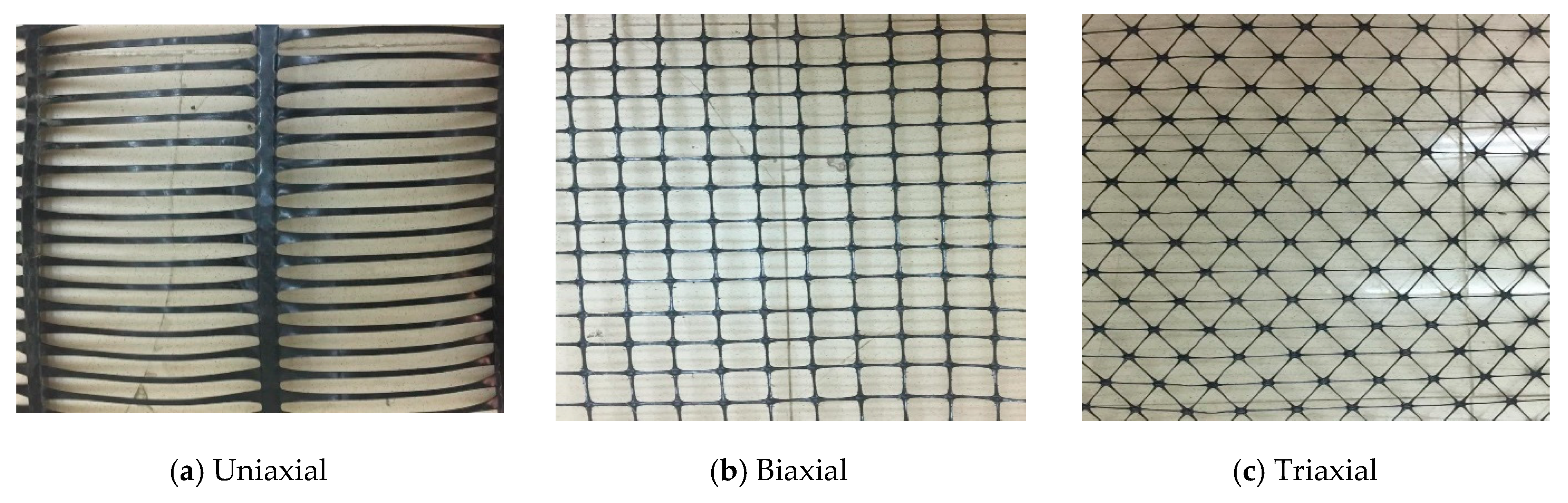
There are three major geogrid categories; uniaxial, biaxial and triaxial. The three geogrid categories are shown in Figure 1. Uniaxial geogrids can mainly be used for grade separating purposes, including retaining walls and steep slopes, while biaxial and triaxial geogrids can be used mainly for roadway uses. This will be defined either through a series of performance characteristics, such as tensile strength and junction efficiency [4].
Geogrid makes it easier to build because it can be installed under any climatic conditions and enables an inappropriate soil to be better prepared for construction requirements, thereby, making it more valuable [1,5]. Using geogrid increases the amount of usable land on a site by permitting steep slopes or walls to be constructed, enabling a highway to be constructed under weak conditions on the ground, or decreasing the filling thickness required for road construction. Lately, the use of geogrids as reinforcements has extended towards pavement networks, especially as stabilizing material in unbound surfaces, reinforcing elements in asphalt layers, and also as interlayers in overlay applications. It has become broadly used for applying geogrids as interlayers to reduce the reflective cracking in pavement overlays in the joined plain concrete pavements [4,6,7,8,9,10,11].
Geogrid is a polymeric material that has a new use in concrete reinforcement. Using geogrid leads to an increase in concrete ductility and improves its ductile behavior in the same manner of using the different fiber-reinforced polymers (FRP) materials. Many researchers introduced the behavior of concrete elements reinforced or strengthened with many types of FRPs like carbon and glass fibers as wraps and sheets [12,13,14,15].
Itani, et al. (2016) [16] used uniaxial geogrid thin concrete overlays to test their effectiveness in preventing cracking. The test results showed that after cracking concrete was assisted by geogrids with ductility and extra load capacity.
Al-Hedad, et al. (2017) [17] tested slab and beam samples reinforced with biaxial geogrid sheets to consider the impact of geogrid use on concrete pavements’ drying shrinkage behavior. Test results showed that, compared to plain concrete samples, geogrids decreased the drying shrinkage strains by 7%−28%.
Uniaxial, biaxial and triaxial geogrids were used by El-Meski and Chehab (2014) [4] to stabilize concrete beams samples subjected to four-points loading. For all geogrid-reinforced samples, a much higher deflection was observed, indicating a ductile post-cracking behavior comparable to the load-deflection patterns of reinforced geogrid and plain concrete beam.
Chidambaram and Agarwal (2014) [7] under compressive, flexural and tensile loading attempted to stabilize concrete specimens with geogrids. It was concluded that the use of geogrids in concrete samples resulted in a significant improvement compared to ordinary reinforcements in the concrete behavior. It was also found that the number of geogrid layers and their mechanical properties had a significant impact on the concrete load deformation behavior.
Kim, et al. (2008) [18] used one and two layers of stiff and flexible biaxial geogrids to explore the behavior of geogrid concrete members. Comparative advantages of using geogrid strengthening advanced after cracking load capacity, ductility, and energy absorption. Stiff geogrids have shown better results than flexible geogrids, which suggests that the geogrid’s physical and mechanical properties are key variables.
Nowadays, self-compacted concrete (SCC) is known to be a commonly used building material that has been developed to satisfy the engineer’s demand for more workable concrete. SCC is used to promote and ensure proper filing and good structural efficiency for extremely congested reinforced structural members or thin members [19,20,21,22,23].
This research aims to investigate the effectiveness of using geogrids on the behavior of concrete slabs as reinforcement for plain concrete slabs and additionally reinforcement to steel in reinforced concrete slab. The current study also introduces two types of geogrid’s surface modification techniques to enhance the bond between geogrid layers and the cement matrix. The geogrid surface modification methods used involved gluing sand to the geogrid surface as a physical surface modification method, and immersion in polycarboxylate as a chemical surface modification method. The effects of geogrid type, number of geogrid layers, and surface modification method on the behavior of high strength self-compacted concrete slabs are discussed.
2. Experimental Program
2.1. Materials
Geogrids: Three types of rigid geogrid (uniaxial, biaxial, and triaxial), were used. Geogrid material was rigid, unwoven, and punch-drawn. The uniaxial type is made of high-density polyethylene. While biaxial and triaxial types are made of polypropylene. Geogrid properties as obtained from the manufacturer are shown in Table 1 and Table 2.
Gluing Material: gluing material used to glue the sand to the geogrid surface as a physical modification method is called “CMB-KEMAPOXY 165”. It is a non-shrinkage epoxy adhesive mortar and grouting compound. “CMB-KEMAPOXY 165” consists of two components mixed together. The first component is the pre-filled viscous medium and the second is the solvent. The two components produced on the basis of modified epoxy resin with an appropriate hardening system. It complies with (ASTM C 881), (BS EN 12004) and (ES 4118) as mentioned by the supplier.
Super-plasticizer: The super-plasticizer used was “Sika-Viscocrete3425”. It is a polycarboxylate-based super-plasticizer supplied to the construction chemicals company by Sika Egypt. It is a third-generation super-plasticizer for concrete and mortar that meets the requirements of ASTM-C-494 super-plasticizer, types G and F [24]. The superplasticizer used has a density of 1.08 kg/lit, a value of 4.0 pH and a solid content of 40% (by weight). In this research, superplasticizer was also used as a source of polycarboxylate that used in the chemical modification method for the geogrid surface. By immersing the geogrid layers in polycarboxylate, new bands appeared on the geogrid surface such as polar carbonyl which improved the hydrophilicity of geogrid that reflected on improving the attachment between geogrid layers and the cement matrix.
Cement: Ordinary Portland cement CEM I N 52.5 was used. Chemical and physical properties of the cement used comply with the Egyptian Standard Specification (E.S.S. 4756-1/2012) [25].
Silica fume: The density and fineness of the used silica fume were 2210 kg/m3 and 23.52 m2/gm respectively. The silica fume used met ASTM C 1240 requirements [26].
Fine aggregate: Natural and clean siliceous sand has been used. The specific gravity of the used sand was 2.71 t/m3. Sand was used as a fine aggregate for the concrete mix. Sand was also used in the physical surface modification technique for geogrid by gluing sand to the geogrid surface.
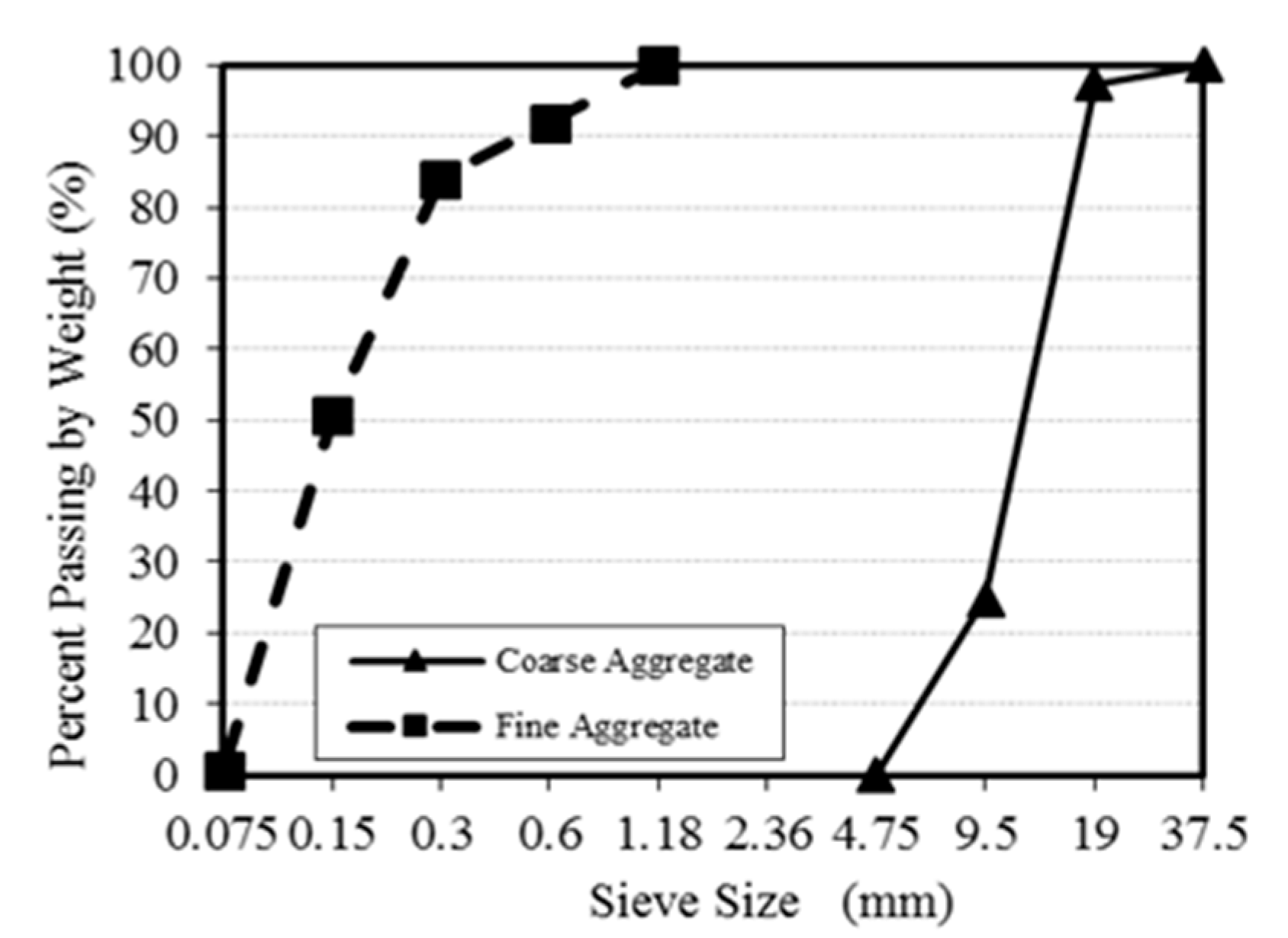
Coarse Aggregate: Crushed dolomite with 12.5 mm maximum nominal size is used as a coarse aggregate. The specific gravity and water absorption were 2.65 t/m3, and 0.6% respectively. Figure 2 displays the grain size distribution curves for the used aggregates.
Steel Reinforcement: Mild steel (St.37) was used as the main reinforcement for the concrete slabs. Two diameters (6 and 8 mm) of steel were used in this experimental work. Table 3 shows the mechanical properties of the used mild steel (St.37).
2.2. Mix Proportions and Properties
Mix proportions chosen based on guidelines and specifications [27] deal with HSSCC and laboratory trials. The proportions of the chosen mix were shown in Table 4.
The used concrete mixture is high strength self-compacted concrete (HSSCC), therefore the fresh concrete tests are very essential to make sure that the mixture meets the self-compacted concrete requirements the British Standard (BS EN 206-9, 2010) [27] and the Egyptian Code of Practice (E.C.P. 203/2018) [28]. The slump flow test was used to determine the mix’s workability while the passing-ability was assessed by the J-ring test. The time needed for concrete to reach a diameter of 500 mm (T50) was 4.0 s (Acceptance range for (T50) = (2−5) seconds). The mean slump flow diameter (Dav) was 66 cm (Acceptance range for (Dav) = (600–800) cm). For the J-ring test, the average diameter (Dav) was measured, and the difference between the average diameter of the slump flow and J-ring tests was 1.5 cm (must not exceed 25 mm). According to (BS EN 206-9, 2010) [27], the used mix is acceptable as a self-compacted concrete. The mechanical properties of the hardened concrete specimens were also determined according to (E.C.P. 203/2018) [28]. The 28 days age compressive, indirect tensile and flexural strength are shown in Table 5. All tests deal with the fresh and hardened properties of the used concrete mix are repeated three times as specified in the Egyptian Code of Practice (E.C.P. 203/2018) [28].
2.3. Specimen Casting and Curing
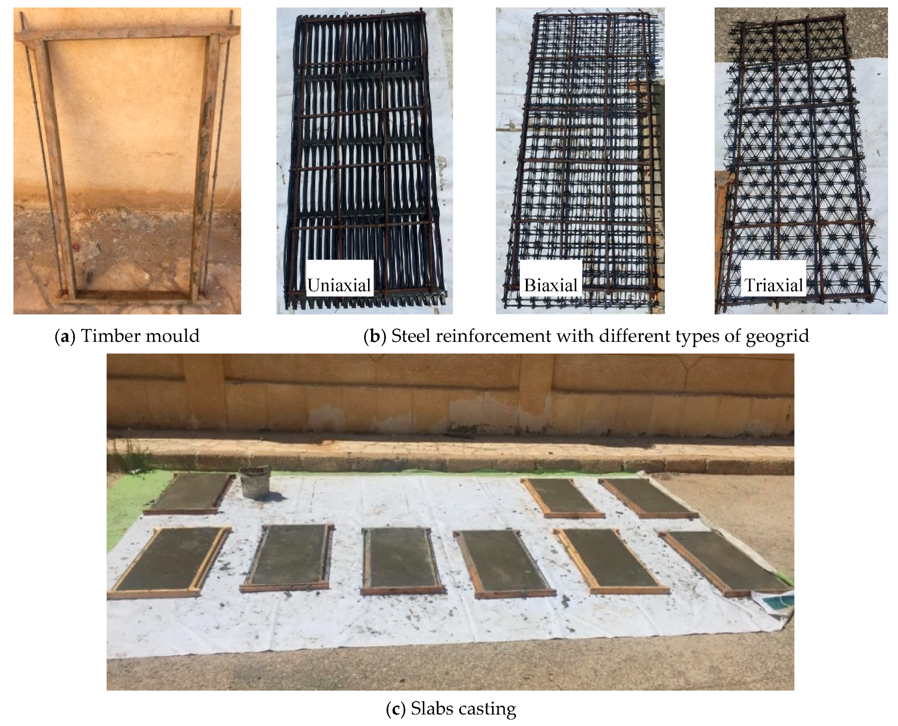
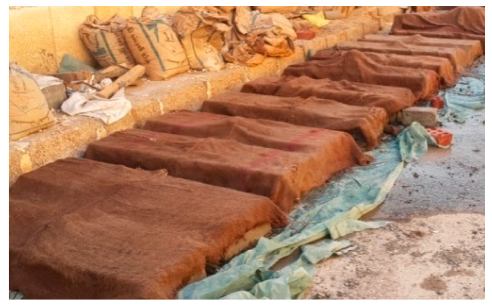
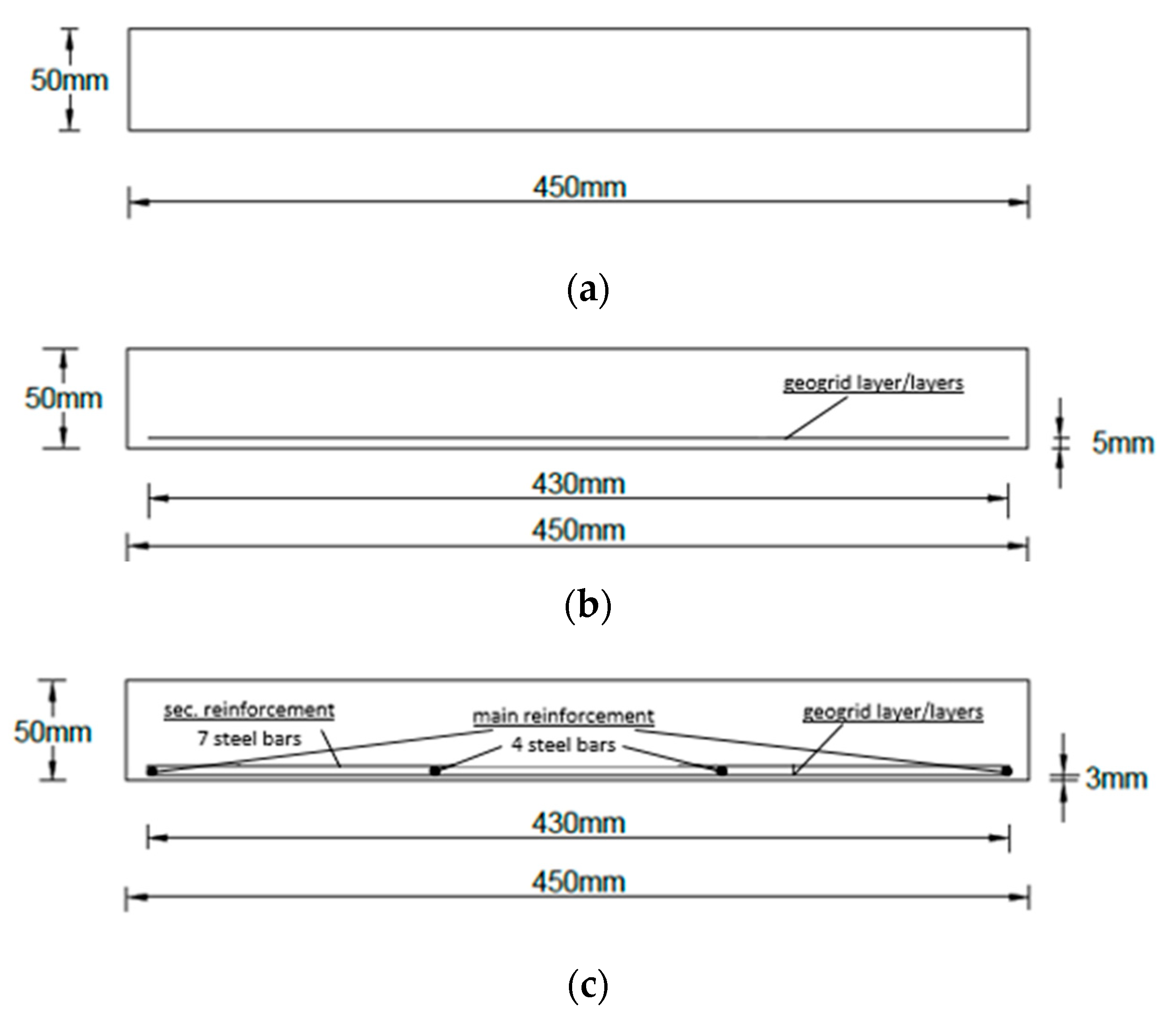
A 34 concrete slabs with dimensions of 1100 × 450 × 50 mm were cast in timber molds as shown in Figure 3. For slabs containing geogrid only, to adjust the geogrid location, 10 nails were installed in the two longitudinal sides of the timber mould. The geogrid layer/layers attached strongly to these nails using steel wires. For slabs containing steel reinforcement or geogrid layers added to steel reinforcement, 8 steel pieces of 3 mm thickness used to adjust the slab’s concrete cover. The concrete slabs were removed from the moulds 24 h after casting, and cured by wet canvas till 28 days age, as shown in Figure 4. The specimens were visually inspected after demolding and no apparent separation or surface cavities were found.
Slabs containing steel reinforcement were reinforced with 4 steel bars in the long direction and 7 steel bars in the short direction. Slabs were reinforced by 6 mm or 8 mm steel bars’ diameter. Figure 5 shows the cross sections for the tested slabs to demonstrate the reinforcement location.
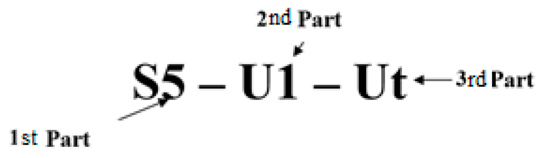
2.4. Nomenclature for Specimens
For easy understanding of each slab model, a system of nomenclature for all slab specimens is introduced in this section. Figure 6 and Table 6 shows the nomenclature for the slab specimens.
- The first part stands for slab thickness for 5 cm-slabs specimens.
- The second part contains of a letter and a number. The letter stands for the type of reinforcement as (P) refers to plain concrete control slab specimens, (U) refers to slabs specimens reinforced with uniaxial geogrids, (B) refers to slabs specimens reinforced with biaxial geogrids, (T) refers to slabs specimens reinforced with triaxial geogrids and (R) refers to slabs specimens containing steel reinforcement. The number stands for the number of geogrid layers used in the reinforcement of the slabs specimens as; (1) refers to one geogrid layer; (2) refers to two geogrid layers; and (3) refers to three geogrid layers. Also, it stands for the bar diameter of steel reinforcement meshes as; (6) refers to the slab specimens reinforced with 6 mm-steel bars; and (8) refers to the slab specimens reinforced with 8 mm-steel bars.
- The third part stands for the type of treatment method of geogrid layers as; (Ut) refers to untreated geogrid layers, (St) refers to geogrid layers glued with sand; and (Vt) refers to geogrid layers immersed in polycarboxylate.
2.5. Three Points Flexural Loading Test
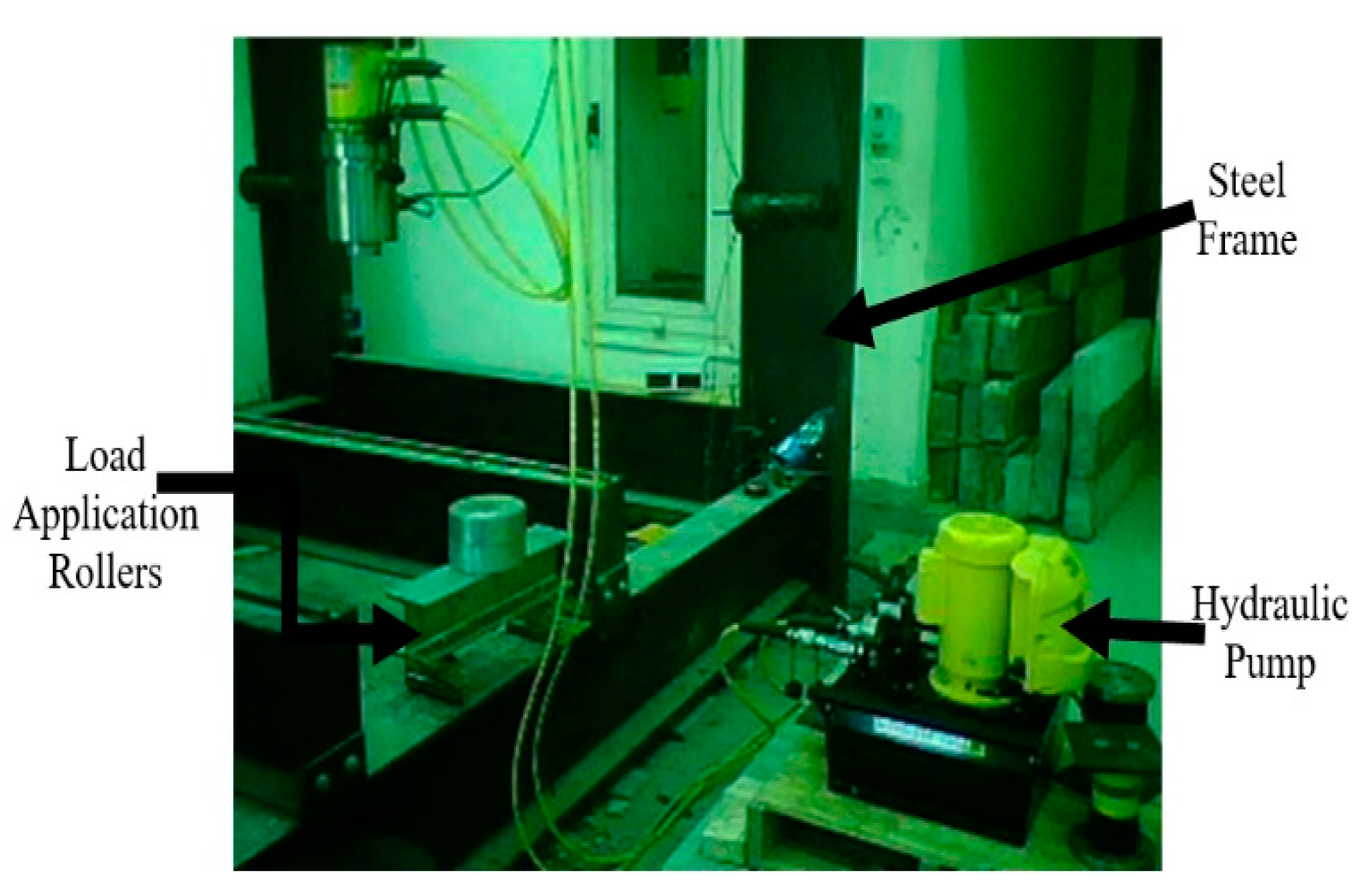
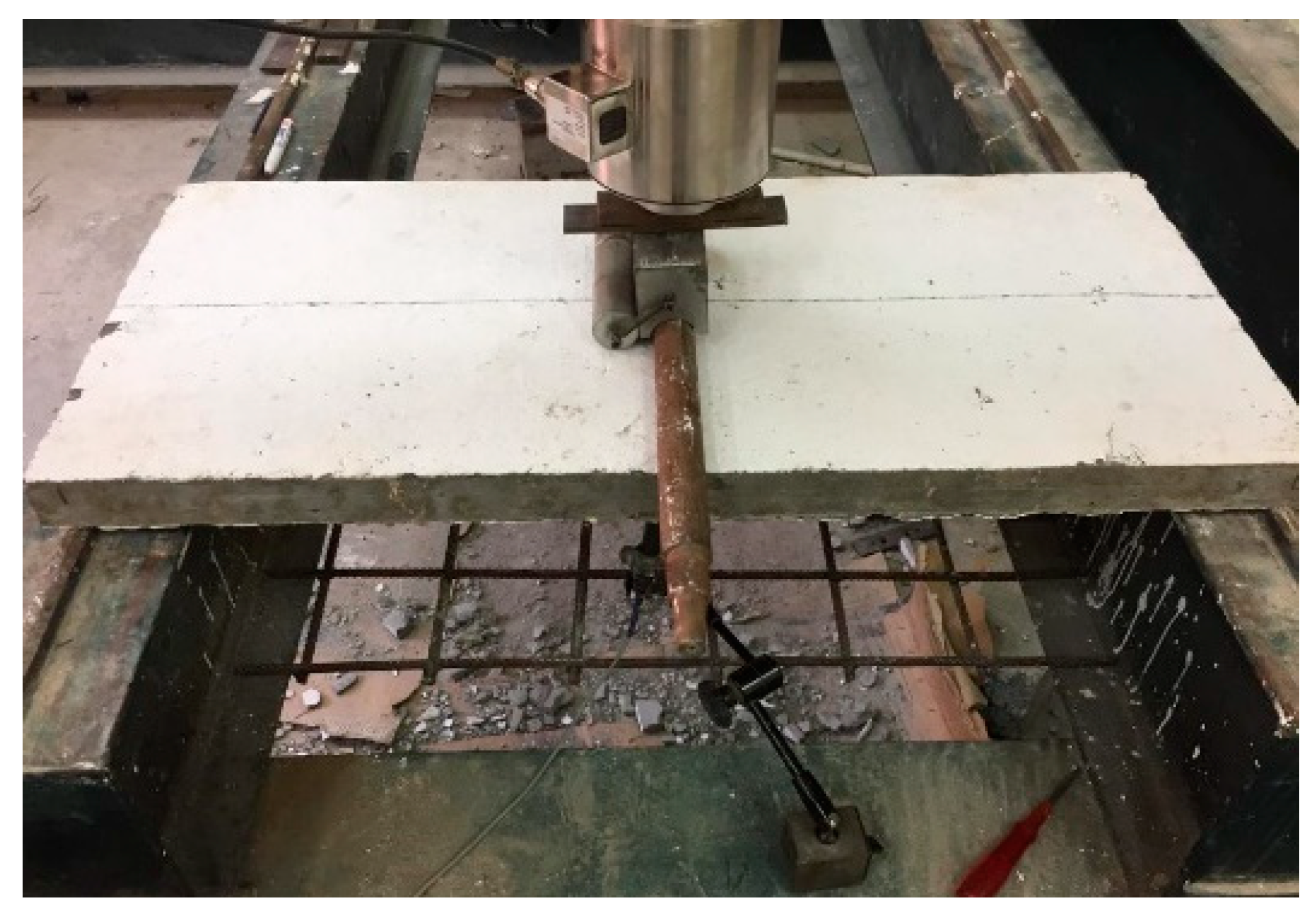
The flexural behavior under three points loading of HSSCC slabs was determined. Figure 7 and Figure 8 show, respectively, the machinery used in the slabs testing. A steel frame was used as a support for slabs with two moving I-beams. A double-acting hydraulic cylinder with a capacity of 150 tons and a maximum stroke of 150 mm, attached to a hydraulic pump, applied the load. A 225-ton load cell was used. The loading process was continuous till failure with loading rate 20 kN/min. An LVDT for measuring displacements up to 100 mm was mounted at the center of its span under each slab to calculate deflections. A data logger was used for displaying continuous records for the applied load and the corresponding deflection. The test ended when the slab load dropped to 75% or less of the maximum load or when the vertical deflection became unduly excessive.
3. Results and Discussion
3.1. Load-Deflection Curves of the Tested Slabs
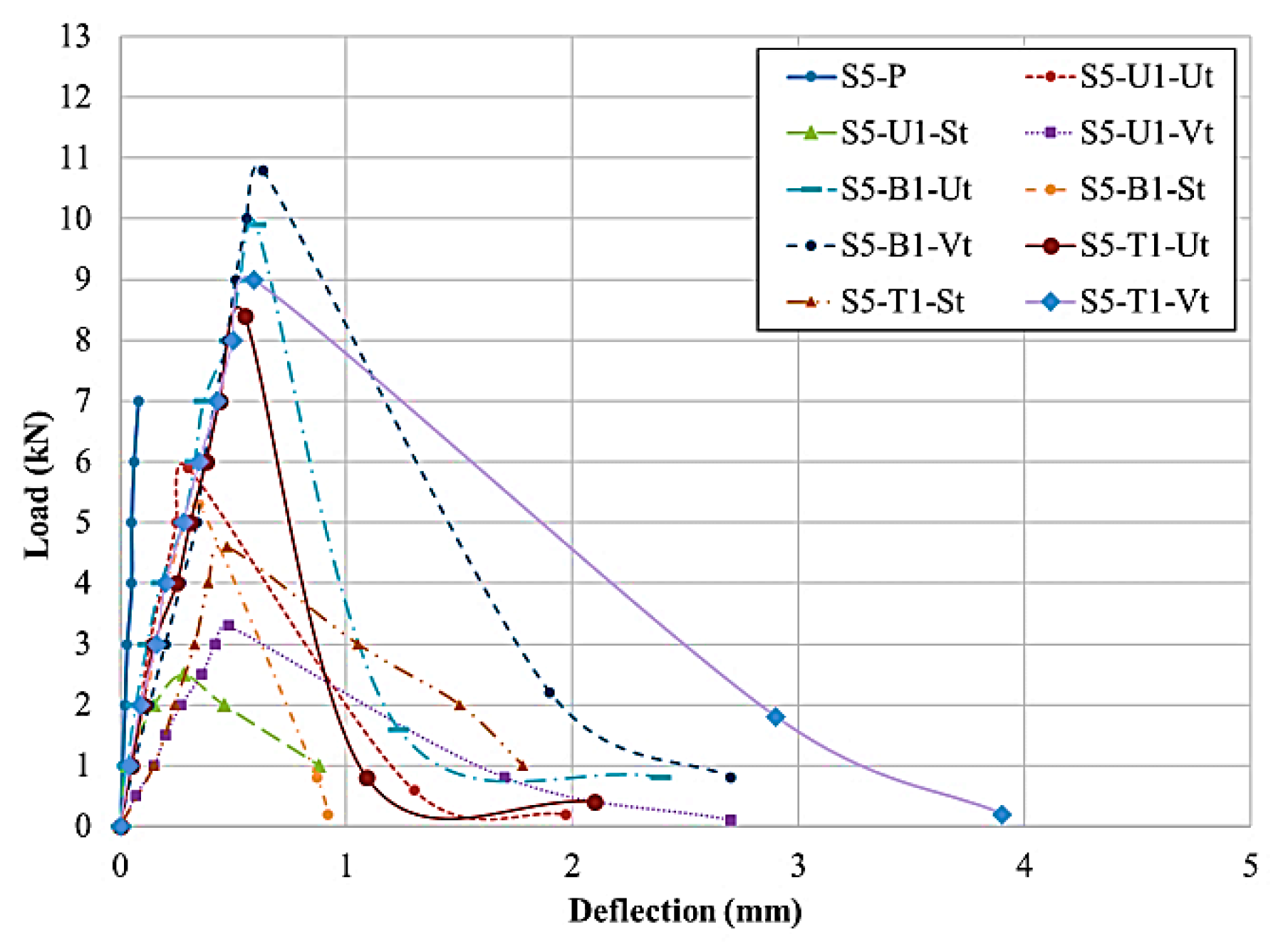
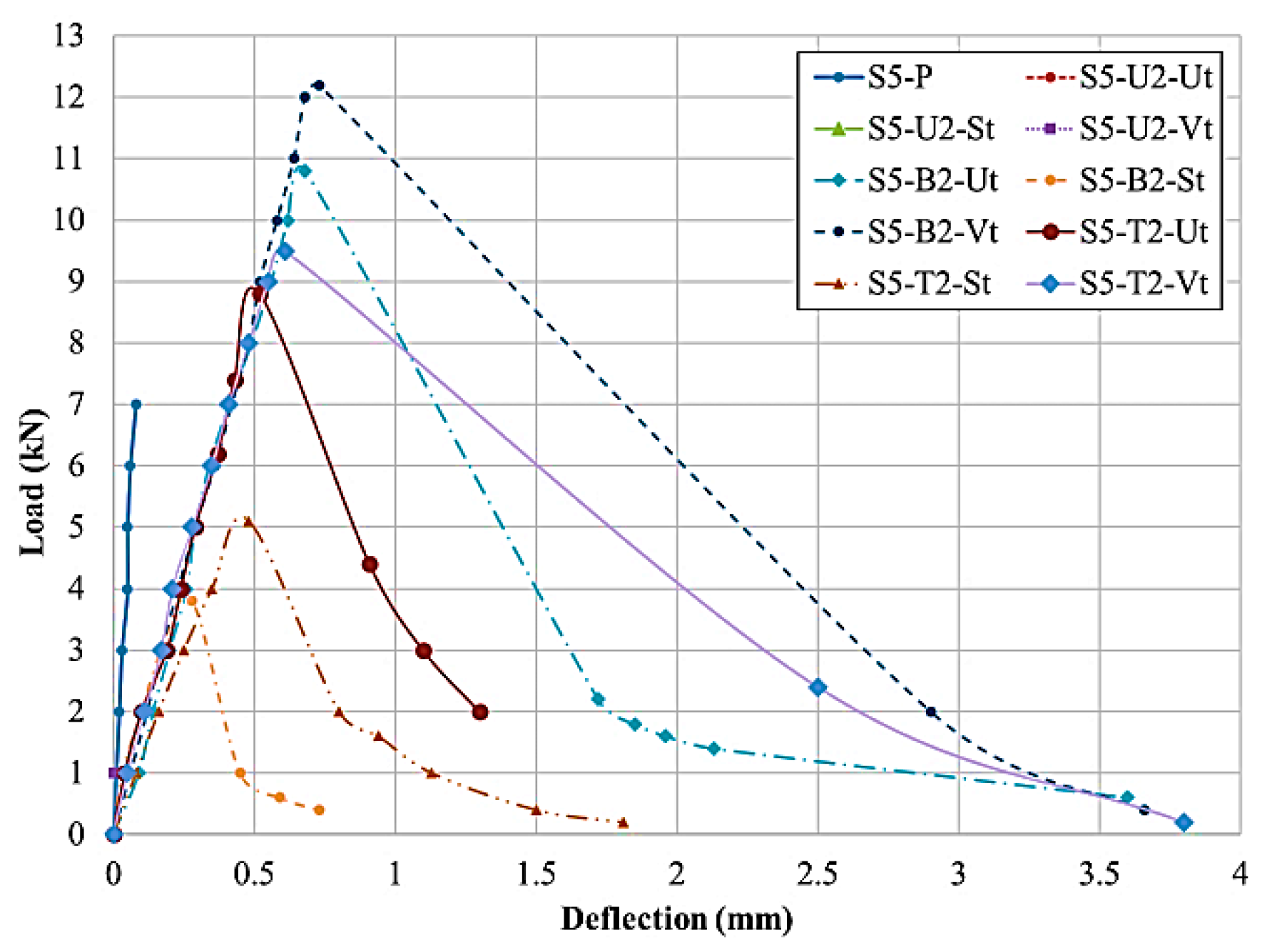
Load-deflection curves for HSSCC 5-cm slabs containing 1 and 2 layers of uniaxial, biaxial and triaxial geogrids are shown in Figure 9 and Figure 10. Based on the obtained Figures, we can see that using physical surface modification by gluing sand to the geogrid surface affected the load-deflection behavior of the geogrid reinforced slabs significantly for the used geogrid types. This bad effect may be caused due to the separation of cement matrix with the glued sand from the geogrid surface because of the weakness of bond between the glue and the geogrid surface. The separation caused the slab to act as a slab with less thickness (about 43 mm). The reduction of the thickness caused reduction of the ultimate loads. While, for slabs containing untreated geogrid layer/layers, the cement matrix attachment to the geogrid surface was very weak.
It was observed that using biaxial geogrid has a good effect on the load-deflection behavior followed by triaxial then uniaxial geogrids. This may be due to the interlocking of concrete into the biaxial geogrid openings, which was better than triaxial and uniaxial geogrids openings. The difference between biaxial and triaxial geogrids is the existence of a cord in the triaxial geogrid that divides the opening to two triangles, and causes the interlock cement matrix block volume to reduce. While, for uniaxial geogrid, the interlocking of cement matrix was very weak due to the long space between junction points. The used geogrid types with different surface modification methods gave deflection values higher than the plain slab as an indication for increasing the ductility of the geogrid reinforced slabs.
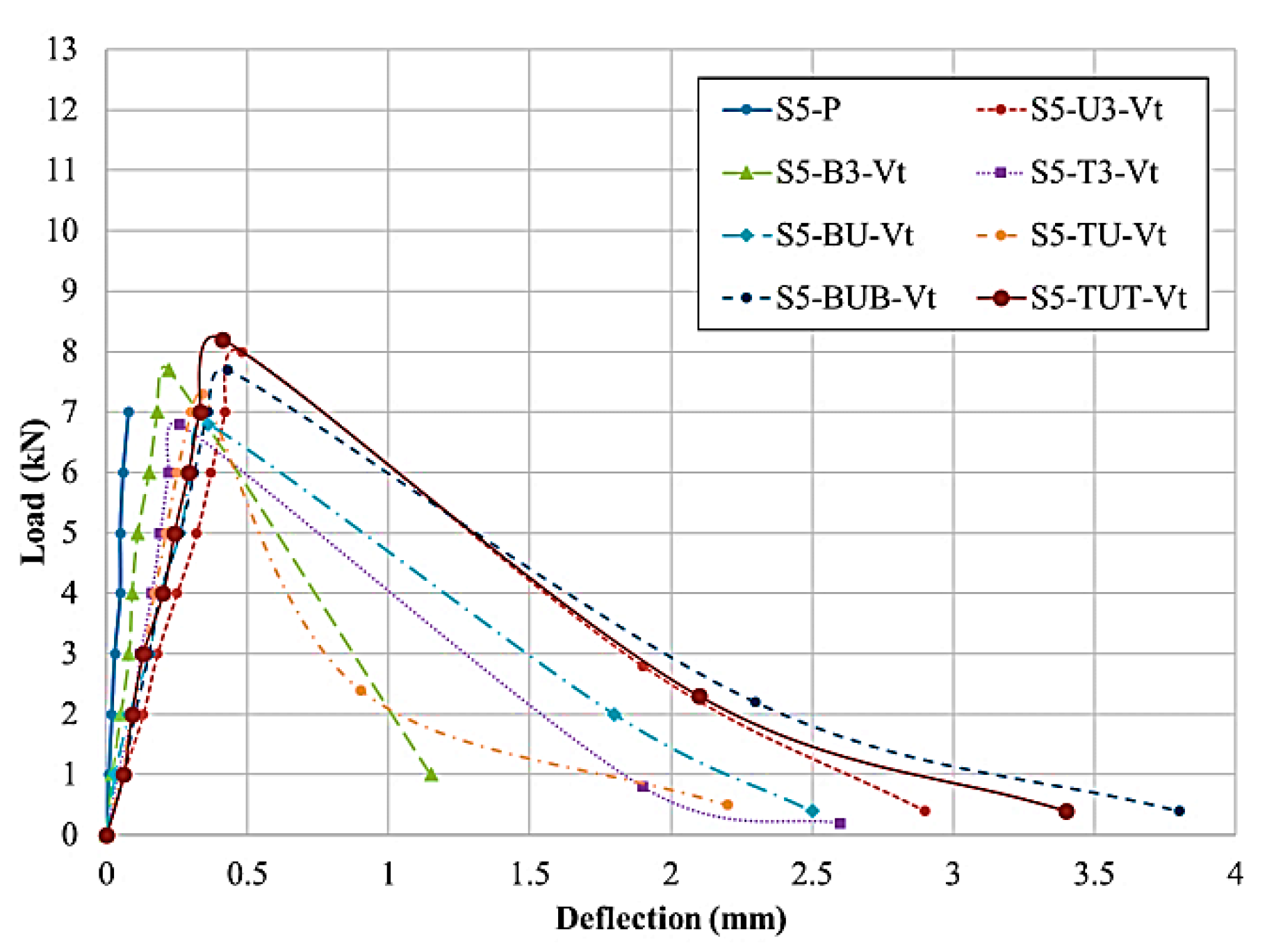
The load-deflection curves for HSSCC 5-cm slabs containing three layers of uniaxial, biaxial and triaxial geogrids and slabs, containing 2 and 3 layers of different geogrid types are shown in Figure 11. From the obtained figure, it could be noticed that using chemical surface modification by immersing the geogrid layers in polycarboxylate had a good effect on the load-deflection behavior of the geogrid reinforced slabs. The results obtained for chemical surface modification were better than that of the used physical surface modification by gluing sand to the geogrid surface. The used physical surface modification affected the load-deflection behavior of the geogrid reinforced slabs badly for the used geogrid types. All specimens gave deflection values higher than the HSSCC plain slab as an indication for increasing the ductility of the geogrid reinforced slabs.
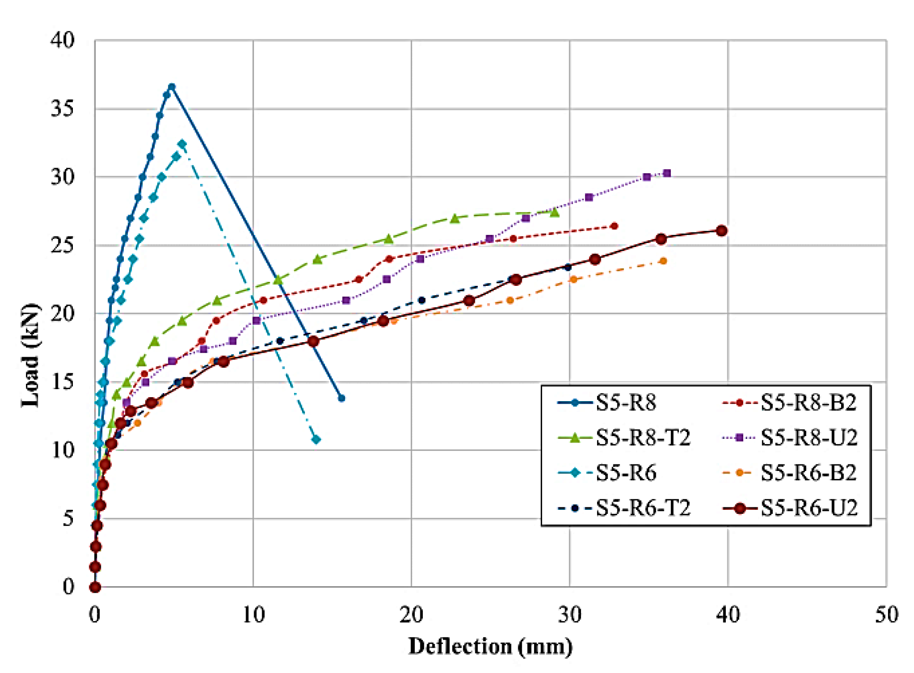
Load-deflection curves for HSSCC 5-cm slabs containing 2 layers of uniaxial, biaxial and triaxial geogrids added to steel reinforcement bars with 8-mm and 6-mm diameters are shown in Figure 12. It was observed from the obtained figure that using uniaxial geogrid with steel reinforcements had a good effect on the load-deflection behavior followed by triaxial and biaxial geogrids. The used geogrid types with steel reinforcements gave deflection values higher than the HSSCC steel reinforced slab as an indication for increasing the ductility of the geogrid reinforced slabs.
3.2. Ultimate and Cracking Loads of the Tested Slabs
In case of HSSCC plain slabs containing geogrid as reinforcement, the cracking and ultimate loads are the same or have slight difference between them that could be neglected. The comparison between slabs with no steel reinforcement will be according to the ultimate loads.
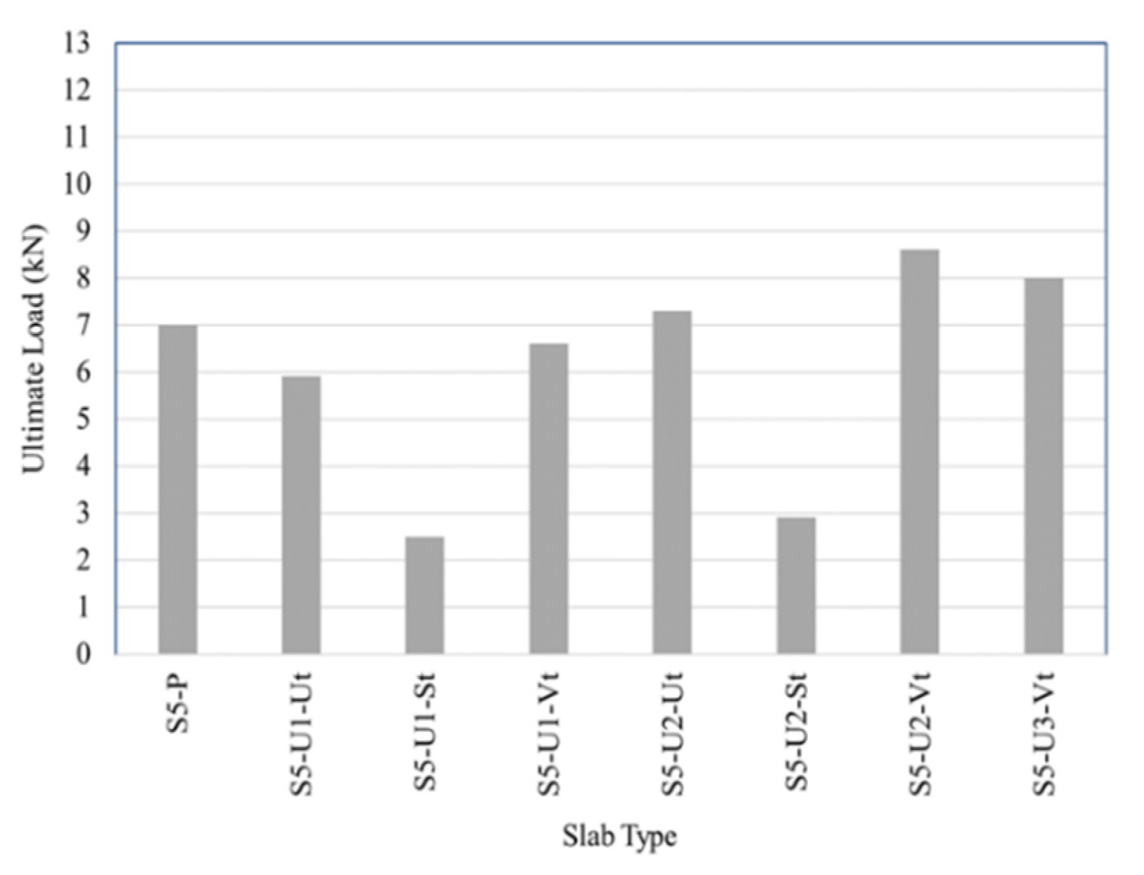
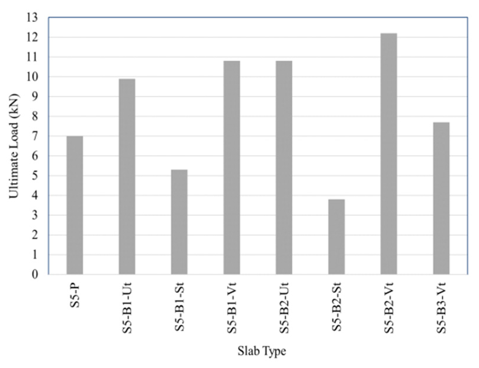
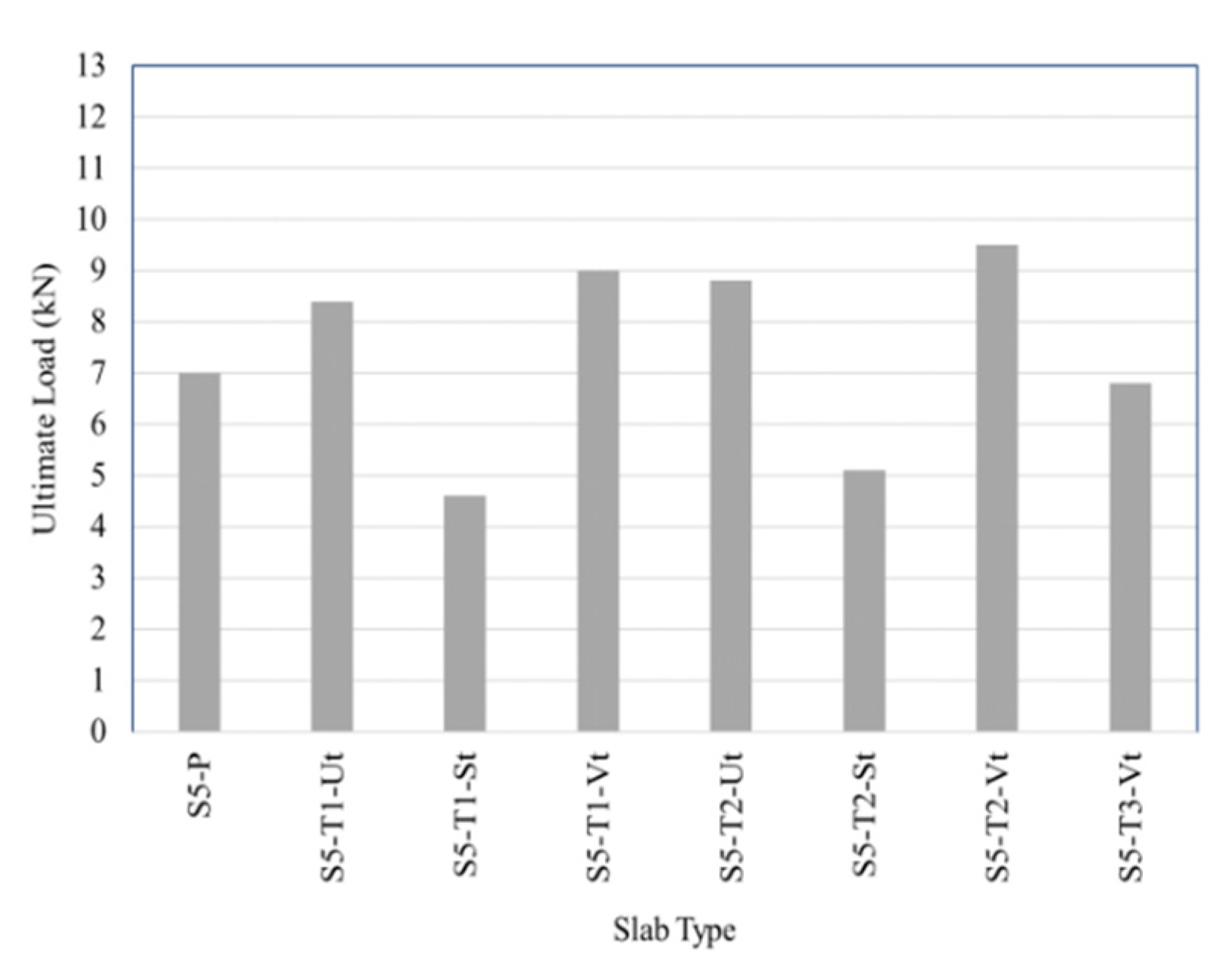
Figure 13, Figure 14 and Figure 15 show the ultimate loads for the tested HSSCC 5-cm slabs containing 1 and 2 layers of uniaxial, biaxial and triaxial geogrids. From the obtained figures, it could be noticed that using physical surface modification by gluing sand to the geogrid surface affected the ultimate loads behavior of the geogrid reinforced slabs badly for the used geogrid types. Also, it was observed that, using biaxial geogrid has a good effect on the ultimate loads’ behavior, followed by triaxial then uniaxial geogrids. Based on the figures, it could be observed that the ultimate load of slabs containing one geogrid layer without any surface modification decreased when compared to HSSCC plain slab by about 16% for uniaxial reinforced slabs, but increased by about 41% for biaxial reinforced slabs and 20% for triaxial reinforced slabs. While, the ultimate load for slabs containing two geogrid layers without any surface modification increased when compared to HSSCC plain slab by about 4% for uniaxial reinforced slabs, 54% for biaxial reinforced slabs and 25% for triaxial reinforced slabs.
Also, figures showed that the chemical modification method for geogrid surface increased the ultimate loads more than the untreated layers and the physical surface modification method. The ultimate loads for slabs containing one geogrid layer with chemical surface modification increased when compared to the untreated slab by about 12% for uniaxial reinforced slabs, 9% for biaxial reinforced slabs and 7% for triaxial reinforced slabs. While, the ultimate loads for the slabs, containing two geogrid layers with chemical surface modification, increased when compared to the untreated slab by about 18% for uniaxial reinforced slabs, 13% for biaxial reinforced slabs and 8% for triaxial reinforced slabs.
The ultimate loads for slabs containing one geogrid layer with chemical surface modification increased when compared to HSSCC plain slab by about 54% for biaxial reinforced slabs and 28% for triaxial reinforced slabs but decreased by about 6% for uniaxial reinforced slabs. While, the ultimate loads for slabs containing two geogrid layers with chemical surface modification increased when compared to HSSCC plain slab by about 23% for uniaxial reinforced slabs, 74% for biaxial reinforced slabs and 35% for triaxial reinforced slabs. Also, the ultimate loads for slabs containing three geogrid layers with chemical surface modification increased when compared to HSSCC plain slab by about 14% for uniaxial reinforced slabs and 10% for biaxial reinforced slabs but decreased by about 3% for triaxial reinforced slabs.
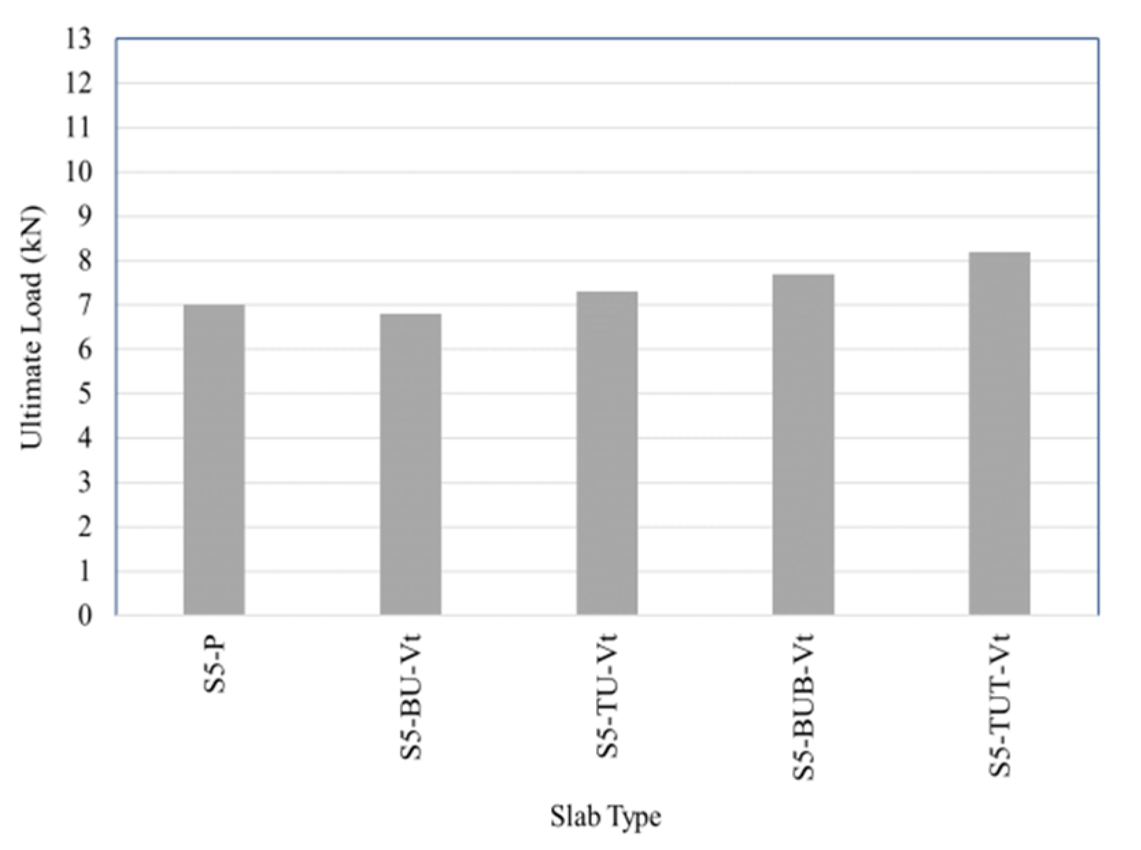
The ultimate loads for HSSCC 5-cm slabs containing 2 and 3 layers of different geogrid types with chemical surface modification; are shown in Figure 16. From the figure, it could be observed that the ultimate loads for slabs containing two geogrid layers decreased when compared to HSSCC plain slab by about 3% for BU slab but increased by about 4% for TU slab. While, the ultimate loads for slabs containing three geogrid layers increased, when compared to HSSCC plain slab by about 10% for BUB slab and 17% for TUT slab. Slabs reinforced with uniaxial and triaxial geogrids combined give ultimate load values higher than slabs reinforced with uniaxial and biaxial geogrids combined.
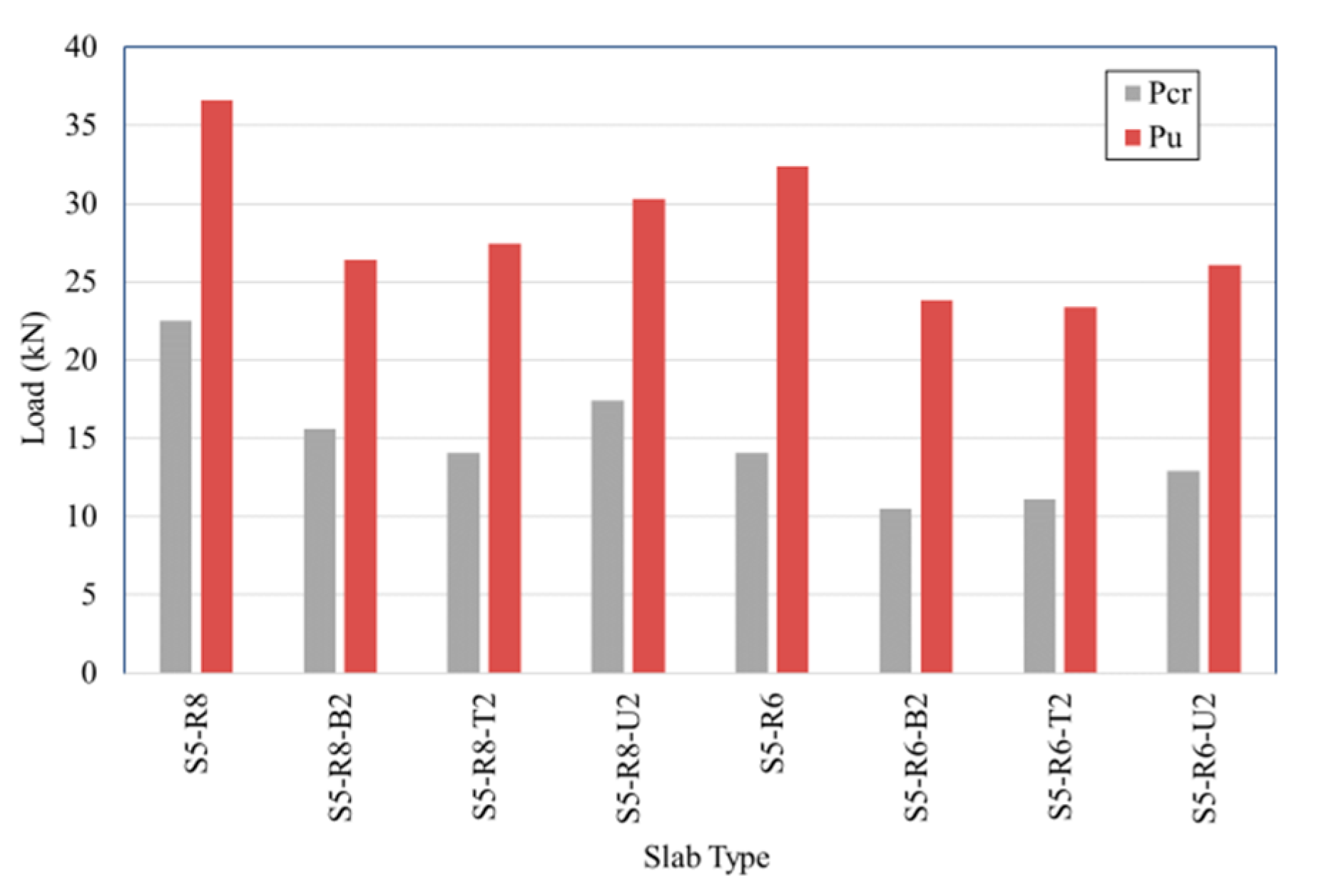
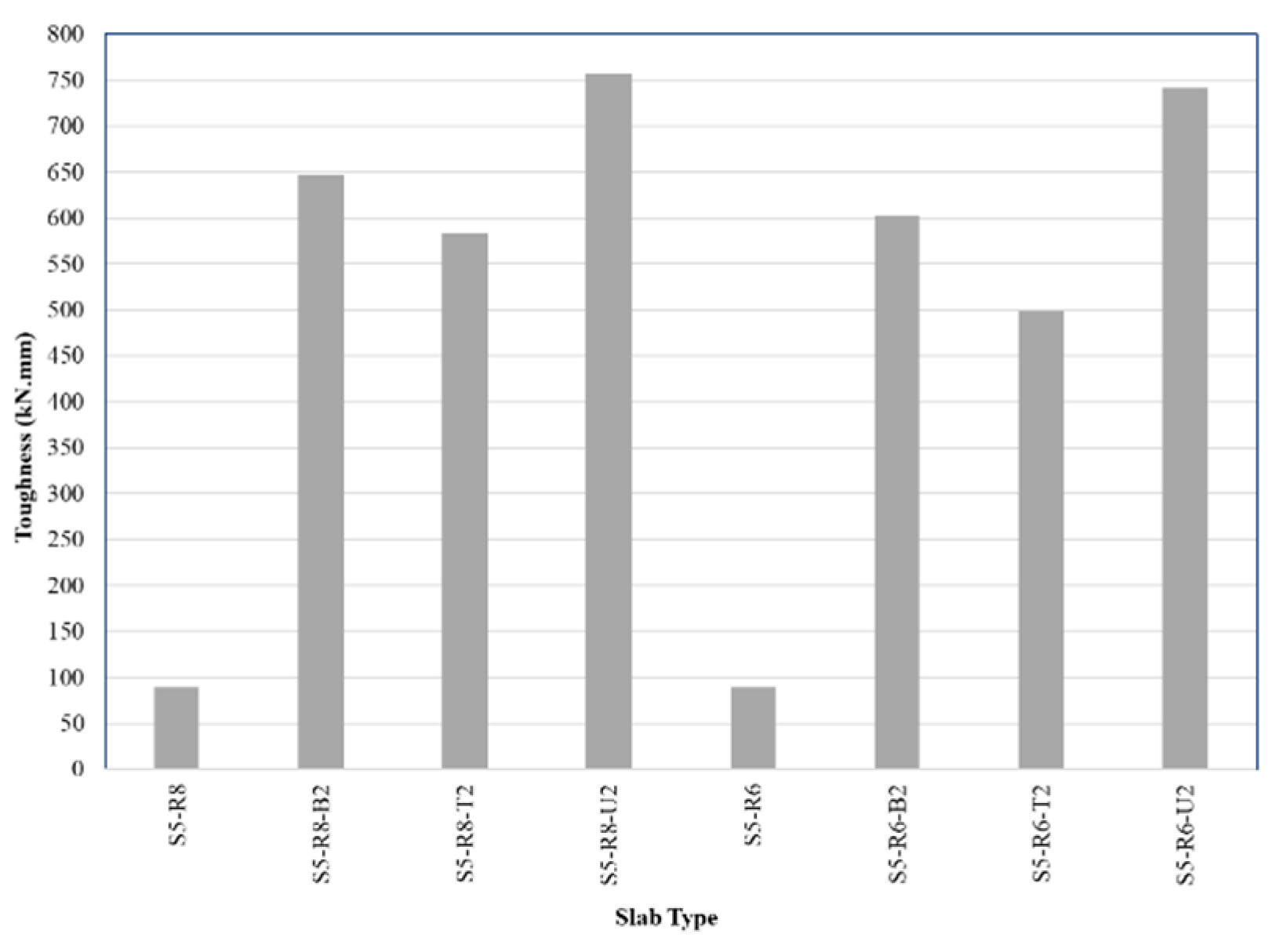
Figure 17 shows the ultimate and cracking loads for HSSCC 5-cm slabs containing two geogrid layers treated with chemical surface modification added to 8-mm and 6-mm steel reinforcement bars, respectively. From the figure, it could be observed that cracking and ultimate loads for slabs containing two geogrid layers added to 8-mm steel reinforcement bars decreased when compared to HSSCC steel reinforced slab by about 31% and 28% for biaxial reinforced slab, 37% and 25% for triaxial reinforced slab, 23% and 17% for uniaxial reinforced slab. Also, the figure showed that the cracking and ultimate loads for slabs containing two geogrid layers added to 6-mm steel reinforcement bars decreased when compared to HSSCC steel reinforced slab by about 25% and 26% for biaxial reinforced slab, 21% and 28% for triaxial reinforced slab, 8.5% and 19% for uniaxial reinforced slab.
3.3. Crack Patterns of the Tested Slabs
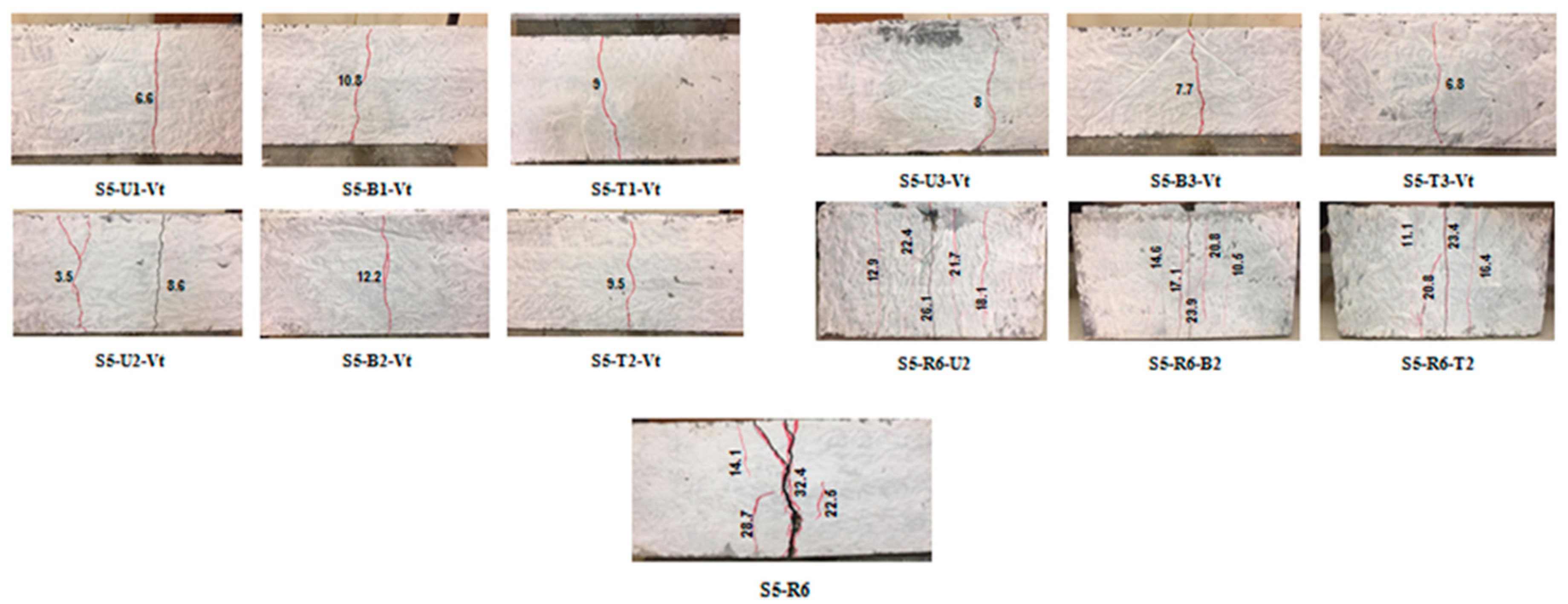
The crack patterns were recorded while loading. Flexural failure was the failure mode for all the tested slabs. From crack patterns of the tested slabs, it could be observed that some slabs reinforced with uniaxial geogrids have two failure cracks located at the ends of the opening under the loading point. Also, it could be observed that the steel reinforced slabs containing additional geogrid reinforcement show crack patterns behavior more ductile than slabs containing steel reinforcement only. Figure 18 shows the crack patterns located at the bottom surface of the tested slabs. The crack patterns were captured while the slabs were under the ultimate loads.
3.4. Absorbed Energy/Toughness of the Tested Slabs
The ductility characterizes the deformation capacity of members (structures) after yielding, or their ability to dissipate energy. In general, ductility is a structural property which is governed by fracture and depends on structure size. A measure of the ductility of a structure may be defined by absorbed energy. The absorbed energy is the area below the load–deflection curve. The more increase in absorbed energy values refers to more slab ductile behavior [29,30,31]. In this research, the absorbed energy was calculated for the area under the curve till the ultimate load.
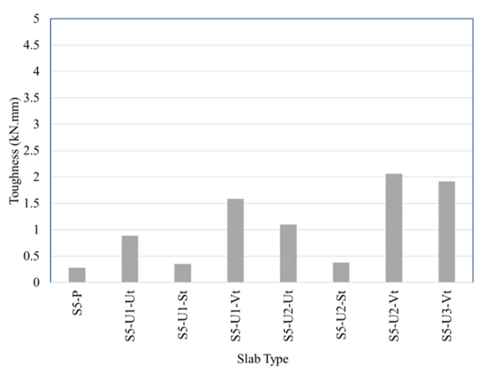
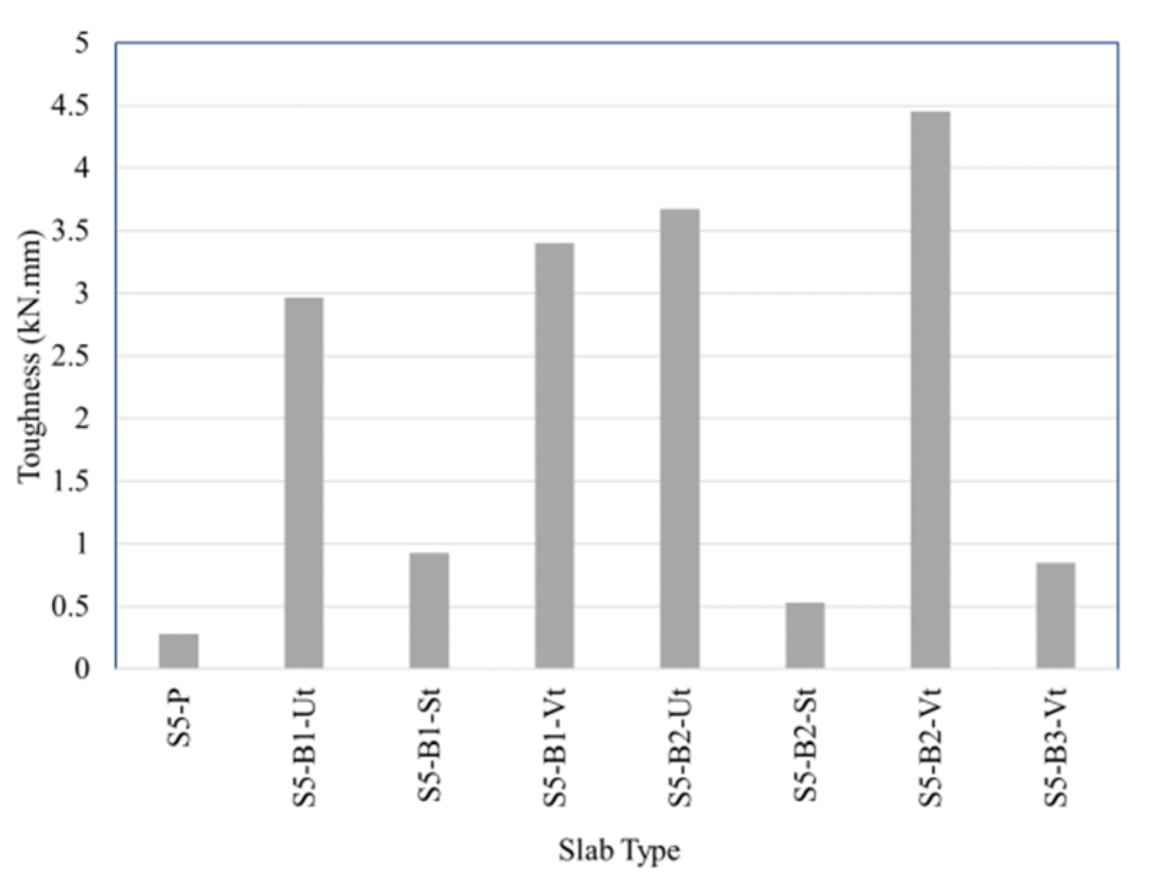
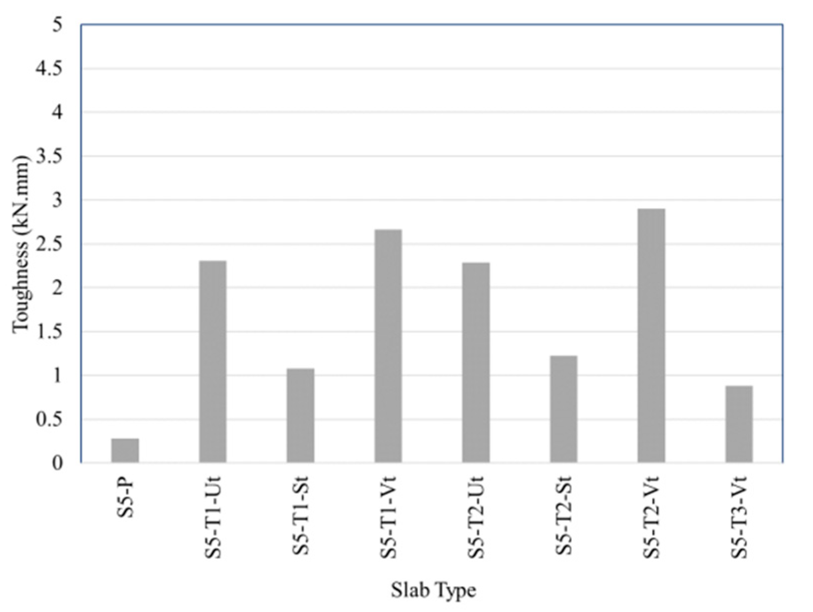
Figure 19, Figure 20 and Figure 21 show the absorbed energy for HSSCC 5-cm slabs reinforced with uniaxial, biaxial and triaxial geogrid types with different surface modification methods. From the figures, it could be observed that the absorbed energy for slabs containing one geogrid layer without any surface modification increased when compared to HSSCC plain slab by about 216% for uniaxial reinforced slabs, 960% for biaxial reinforced slabs and 725% for triaxial reinforced slabs. While, the absorbed energy for slabs containing two geogrid layers without any surface modification increased when compared to HSSCC plain slab by about 293% for uniaxial reinforced slabs, 1211.5% for biaxial reinforced slabs and 717% for triaxial reinforced slabs.
Figures also showed that the chemical modification method for geogrid surface increased the absorbed energy more than the untreated layers and the physical surface modification method. The absorbed energy for slabs containing one geogrid layer with chemical surface modification increased, when compared to the untreated slab by about 79% for uniaxial reinforced slabs, 14.5% for biaxial reinforced slabs and 15.2% for triaxial reinforced slabs. While, the absorbed energy for slabs containing two geogrid layers with chemical surface modification increased when compared to the untreated slab by about 87.3% for uniaxial reinforced slabs, 21.3% for biaxial reinforced slabs and 26.75% for triaxial reinforced slabs.
The absorbed energy for slabs containing one geogrid layer with chemical surface modification increased when compared to HSSCC plain slab by about 465% for uniaxial reinforced slabs, 1115% for biaxial reinforced slabs and 850% for triaxial reinforced slabs. While, the absorbed energy for slabs containing two geogrid layers with chemical surface modification increased when compared to HSSCC plain slab by about 635% for uniaxial reinforced slabs, 1490% for biaxial reinforced slabs and 935% for triaxial reinforced slabs. Also, the absorbed energy for slabs containing three geogrid layers with chemical surface modification increased when compared to HSSCC plain slab by about 585% for uniaxial reinforced slabs, 203% for biaxial reinforced slabs and 216% for triaxial reinforced slabs. Slabs reinforced with biaxial geogrid recorded absorbed energy values higher than slabs reinforced with triaxial and uniaxial geogrids which mean that they are more ductile.
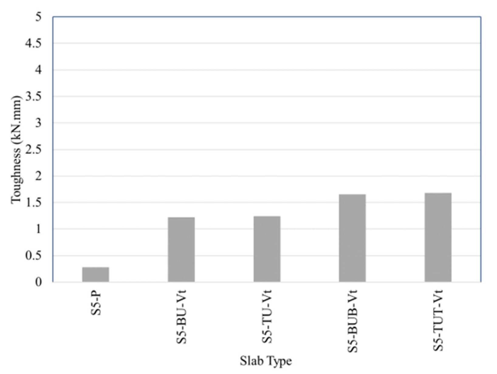
The absorbed energy for HSSCC 5-cm slabs, containing 2 and 3 layers of different geogrid types with chemical surface modification, is shown in Figure 22. From that Figure, it could be observed that the absorbed energy for slabs containing two geogrid layers increased when compared to HSSCC plain slab by about 337% for BU slab and 344% for TU slab. While, the absorbed energy for slabs containing three geogrid layers increased when compared to HSSCC plain slab by about 491% for BUB slab and 500% for TUT slab. The slabs reinforced with uniaxial and triaxial geogrids, combined, recorded absorbed energy values higher than slabs reinforced with uniaxial and biaxial geogrids combined, which mean that they have the higher ductility.
Figure 23 shows the absorbed energy for HSSCC 5-cm slabs containing two geogrid layers treated with chemical surface modification added to 8-mm and 6-mm steel reinforcement bars, respectively. From the figure, it could be observed that absorbed energy for slabs containing two geogrid layers added to 8-mm steel reinforcement bars increased when compared to HSSCC steel reinforced slab by about 751% for uniaxial reinforced slab, 628% for biaxial reinforced slab and 556% for triaxial reinforced slab. Also, figure showed that absorbed energy for slabs containing two geogrid layers added to 6-mm steel reinforcement bars increased when compared to HSSCC steel reinforced slab by about 730% for uniaxial reinforced slab, 574% for biaxial reinforced slab and 457% for triaxial reinforced slab. Figure indicated that slabs reinforced with uniaxial geogrid added to steel reinforcement recorded absorbed energy values higher than slabs reinforced with biaxial then triaxial geogrids which mean that they are more ductile.
4. Conclusions
The conclusions of the test results of the executed experimental program on the HSSCC slabs, containing geogrid as plain concrete slabs reinforcement, or as additionally reinforcement to steel in reinforced concrete slabs, can be summarized as follow:
- Using geogrids for the reinforcement of HSSCC plain concrete slabs has a good effect on the load-deflection behavior of slabs and improved their ductility.
- Treating geogrid using chemical surface modification method (immersing in polycarboxylate) gives results higher than untreated layers and geogrid treated with physical surface modification method.
- Using physical surface modification method for geogrid surface by gluing sand with the used type of glue and the used grade of sand affected the ultimate loads behavior badly.
- Using two geogrid layers as reinforcement for plain concrete slab gives results higher than using one and three geogrid layers for the used geogrid types.
- Using biaxial geogrid as reinforcement for plain concrete slab gives higher results than uniaxial and triaxial geogrids, particularly when two layers of each type are used.
- The HSSCC 5-cm slab containing two biaxial geogrid layers treated with the used chemical surface modification method gives the highest values in ultimate load and absorbed energy. The slab’s ultimate load increased when compared to the untreated reinforced slab by about 13% and 74% when compared to the plain HSSCC slab.
- Using three layers of two geogrid types (one uniaxial layer between two triaxial layers) gives results better than using three triaxial geogrid only as the slab’s ultimate load, increased by about 20%, but still less than 2 layers of triaxial only.
- Using two geogrid layers treated with the used chemical surface modification method as additional reinforcement to the HSSCC 5-cm slabs, containing steel reinforcement bars decreased the ultimate loads by about 18% for uniaxial reinforced slabs, 27% for biaxial reinforced slabs and 26.5% for triaxial reinforced slabs when compared to steel reinforced slabs.
- Using two geogrid layers treated with the used chemical surface modification method as additional reinforcement to the HSSCC 5-cm slabs containing steel reinforcement bars increased the absorbed energy by about 496% for uniaxial reinforced slabs, 383% for biaxial reinforced slabs and 320% for triaxial reinforced slabs when compared to steel reinforced slabs as an indication for the great improvement of the slab’s ductility.
- The behavior of slabs containing two layers of chemically treated geogrid is the same for the two used steel reinforcement ratios.
Author Contributions
All authors contributed extensively to this study, discussed the results and reviews, prepared the manuscript and agreed to the amendments at all stages of the paper. All authors have read and agreed to the published version of the manuscript.
Funding
This research received no external funding.
Conflicts of Interest
The authors declare no conflict of interest.
References
- Tang, X.; Chehab, G.R.; Palomino, A. Evaluation of geogrids for stabilising weak pavement subgrade. Int. J. Pavement Eng. 2008, 9, 413–429. [Google Scholar] [CrossRef]
- Abu-Farsakh, M.Y.; Akond, I.; Chen, Q. Evaluating the performance of geosynthetic-reinforced unpaved roads using plate load tests. Int. J. Pavement Eng. 2016, 17, 901–912. [Google Scholar] [CrossRef]
- Reddy, P.M.; Kumar, J.R. Study of geo-grid confined reinforced concrete beams. Int. J. Sci. Eng. Technol. Res. (IJSETR) 2018, 7, 278–286. [Google Scholar]
- El Meski, F.; Chehab, G. Flexural behavior of concrete beams reinforced with different types of geogrids. J. Mater. Civ. Eng. 2014, 26, 04014038. [Google Scholar] [CrossRef]
- Arulrajah, A.; Rahman, M.A.; Piratheepan, J.; Bo, M.; Imteaz, M. Evaluation of interface shear strength properties of geogrid-reinforced construction and demolition materials using a modified large-scale direct shear testing apparatus. J. Mater. Civ. Eng. 2014, 26, 974–982. [Google Scholar] [CrossRef]
- Abdesssemed, M.; Kenai, S.; Bali, A. Experimental and numerical analysis of the behavior of an airport pavement reinforced by geogrids. Constr. Build. Mater. 2015, 94, 547–554. [Google Scholar] [CrossRef]
- Chidambaram, R.S.; Agarwal, P. The confining effect of geo-grid on the mechanical properties of concrete specimens with steel fiber under compression and flexure. Constr. Build. Mater. 2014, 71, 628–637. [Google Scholar] [CrossRef]
- Chidambaram, R.S.; Agarwal, P. Flexural and shear behavior of geo-grid confined RC beams with steel fiber reinforced concrete. Constr. Build. Mater. 2015, 78, 271–280. [Google Scholar] [CrossRef]
- Siva Chidambaram, R.; Agarwal, P. Inelastic behaviour of RC beams with steel fibre and polymer grid confinement. Indian Concr. J. 2015, 89, 83–90. [Google Scholar]
- Wang, W.; Sheikh, M.N.; Hadi, M.N. Axial compressive behaviour of concrete confined with polymer grid. Mater. Struct. 2016, 49, 3893–3908. [Google Scholar] [CrossRef]
- Tang, X.; Higgins, I.; N Jlilati, M. Behavior of Geogrid-Reinforced Portland Cement Concrete under Static Flexural Loading. Infrastructures 2018, 3, 41. [Google Scholar] [CrossRef] [Green Version]
- Chalioris, C.E.; Zapris, A.G.; Karayannis, C.G. U-Jacketing Applications of Fiber-Reinforced Polymers in Reinforced Concrete T-Beams against Shear—Tests and Design. Fibers 2020, 8, 13. [Google Scholar] [CrossRef] [Green Version]
- Abdulhameed, A.A.; Said, A.I. CFRP Laminates Reinforcing Performance of Short-Span Wedge-Blocks Segmental Beams. Fibers 2020, 8, 6. [Google Scholar] [CrossRef] [Green Version]
- Jaafer, A.A.; AL-Shadidi, R.; Kareem, S.L. Enhancing the Punching Load Capacity of Reinforced Concrete Slabs Using an External Epoxy-Steel Wire Mesh Composite. Fibers 2019, 7, 68. [Google Scholar] [CrossRef] [Green Version]
- Chalioris, C.E.; Kosmidou, P.-M.K.; Papadopoulos, N.A. Investigation of a new strengthening technique for RC deep beams using carbon FRP ropes as transverse reinforcements. Fibers 2018, 6, 52. [Google Scholar] [CrossRef] [Green Version]
- Itani, H.; Saad, G.; Chehab, G. The use of geogrid reinforcement for enhancing the performance of concrete overlays: An experimental and numerical assessment. Constr. Build. Mater. 2016, 124, 826–837. [Google Scholar] [CrossRef]
- Al-Hedad, A.S.; Bambridge, E.; Hadi, M.N. Influence of geogrid on the drying shrinkage performance of concrete pavements. Constr. Build. Mater. 2017, 146, 165–174. [Google Scholar] [CrossRef] [Green Version]
- Kim, S.; Tang, X.; Chehab, G.R. Laboratory study of geogrid reinforcement in portland cement concrete. In Pavement Cracking: Mechanisms, Modeling, Detection, Testing and Case Histories; CRC Press: Boca Raton, FL, USA, 2008; pp. 769–778. [Google Scholar]
- Al-Hadithi, A.I.; Hilal, N.N. The possibility of enhancing some properties of self-compacting concrete by adding waste plastic fibers. J. Build. Eng. 2016, 8, 20–28. [Google Scholar] [CrossRef]
- Khaloo, A.; Raisi, E.M.; Hosseini, P.; Tahsiri, H. Mechanical performance of self-compacting concrete reinforced with steel fibers. Constr. Build. Mater. 2014, 51, 179–186. [Google Scholar] [CrossRef]
- Chalioris, C.E.; Pourzitidis, C.N. Rehabilitation of shear-damaged reinforced concrete beams using self-compacting concrete jacketing. ISRN Civ. Eng. 2012, 2012. [Google Scholar] [CrossRef] [Green Version]
- Mahoutian, M.; Shekarchi, M. Effect of inert and pozzolanic materials on flow and mechanical properties of self-compacting concrete. J. Mater. 2015, 2015. [Google Scholar] [CrossRef] [Green Version]
- Hassan, H.M.; Arab, M.A.E.S.; Ismail el-kassas, A. Behavior of high strength self compacted concrete deep beams with web openings. Heliyon 2019, 5, e01524. [Google Scholar] [CrossRef] [PubMed] [Green Version]
- ASTM. ASTM C494: Chemical Admixtures; ASTM International: West Conshohocken, PA, USA, 2003. [Google Scholar]
- Egyptian Organization for Standards & Quality. E.S.S. 4756-1/2009: Egyptian Standard Specification for Ordinary Portland Cement; Egyptian Organization for Standards & Quality: Cairo, Egypt, 2009. [Google Scholar]
- ASTM. ASTM C1240-05: Standard Specification for Silica Fume Used in Cementitious Mixtures; ASTM International: West Conshohocken, PA, USA, 2005. [Google Scholar]
- EN, B. 206-9 2010 Concrete, Part 9: Additional Rules for Selfcompacting Concrete (SCC); British Standards Institution: London, UK, 2010. [Google Scholar]
- Committee, E.-P. Egyptian Code of Practice for Design and Construction of Concrete Structures; Ministry of Housing Cairo: Cairo, Egypt, 2018.
- Buyukozturk, O. Mechanics and Design of Concrete Structures; Massachusetts Institute of Technology, Cambridge: Cambridge, MA, USA, 2004. [Google Scholar]
- Mohammadhassani, M.; Jumaat, M.Z.; Jameel, M.; Badiee, H.; Arumugam, A.M. Ductility and performance assessment of high strength self compacting concrete (HSSCC) deep beams: An experimental investigation. Nucl. Eng. Des. 2012, 250, 116–124. [Google Scholar] [CrossRef]
- Ismail el-kassas, A.; Hassan, H.M.; Arab, M.A.E.S. Effect of Longitudinal Opening on The Structural Behavior of Reinforced High-Strength Self-Compacted Concrete Deep Beams. Case Stud. Constr. Mater. 2020, 12, e00348. [Google Scholar]
Figure 1.
Geogrid types.

Figure 2.
Grain size distribution curves for used aggregates.

Figure 3.
Timber moulds, steel reinforcement with different types of geogrid and slabs casting.

Figure 4.
Slabs curing with wet canvas.

Figure 5.
The cross sections of the tested slabs. (a) Plain concrete slab; (b) Geogrid reinforced concrete slab; (b) Geogrid reinforced concrete slab.
Figure 5.
The cross sections of the tested slabs. (a) Plain concrete slab; (b) Geogrid reinforced concrete slab; (b) Geogrid reinforced concrete slab.

Figure 6.
Nomenclature for specimens.

Figure 7.
Testing equipment.

Figure 8.
Sample under testing equipment.

Figure 9.
Load-deflection curves for slabs with 1 layer of geogrid.

Figure 10.
Load-deflection curves for slabs with 2 layers of geogrid.

Figure 11.
Load-deflection curves for slabs with three layers of geogrid and slabs containing two and three layers of different geogrid types.
Figure 11.
Load-deflection curves for slabs with three layers of geogrid and slabs containing two and three layers of different geogrid types.

Figure 12.
Load-deflection curves for slabs with steel reinforcement and two layers of geogrid.

Figure 13.
Ultimate loads for slabs with uniaxial geogrid type.

Figure 14.
Ultimate loads for slabs with biaxial geogrid type.

Figure 15.
Ultimate loads for slabs with triaxial geogrid type.

Figure 16.
Ultimate loads for slabs containing two and three layers of different geogrid types.

Figure 17.
Ultimate loads for slabs with steel reinforcement and two layers of geogrid.

Figure 18.
Examples for the crack pattern of tested slabs.

Figure 19.
Absorbed energy for slabs with uniaxial geogrid type.

Figure 20.
Absorbed energy for slabs with biaxial geogrid type.

Figure 21.
Absorbed energy for slabs with triaxial geogrid type.

Figure 22.
Absorbed energy for slabs containing 2 and 3 layers of different geogrid types.

Figure 23.
Absorbed energy for slabs with steel reinforcement and 2 layers of geogrid.


Table 1.
Physical and mechanical properties of the used triaxial geogrid.
| Performance Related to Physical Properties of the Product | Product Characteristic | Unit | Declared Value | Tolerance |
| Radial Secant Stiffness at 0.5% strain | kN/m | 390 | −75 | |
| Radial Secant Stiffness Ratio | - | 0.80 | −0.15 | |
| Junction Efficiency | % | 100 | −10 | |
| Properties for Identification of the Product | Radial Secant Stiffness at 2% strain | kN/m | 290 | −65 |
| Hexagon Pitch | mm | 80 | ±4 | |
| Weight of the product | kg/m2 | 0.220 | −0.035 |
Table 2.
Physical and mechanical properties of the used uniaxial and biaxial geogrids.
| Component | Description | Unit | |
|---|---|---|---|
| Uniaxial | Biaxial | ||
| Tensile Strength at 2% strain | 17 | 14 | kN/m |
| Tensile Strength at 5% strain | 32 | 28 | kN/m |
| Peak tensile strength | 60 | 40 | kN/m |
| Yield point elongation | 13 | 11 | % |
| Junction strength | 95 | 95 | % |
Table 3.
Mechanical properties of the steel reinforcement.
| Steel Type | Diameter | Yield Stress | Tensile Strength | Elongation |
|---|---|---|---|---|
| (mm) | (Kg/cm2) | (Kg/cm2) | (%) | |
| Mild St. | 8 | 2950 | 3990 | 24.2 |
| 6 | 2520 | 3860 | 27.5 |
Table 4.
Concrete mixture proportions (Kg/m3).
| Cement | Silica Fume | Water | Fine Aggregate | Coarse Aggregate | Super- Plasticizer |
|---|---|---|---|---|---|
| 500 | 25 | 168 | 810 | 810 | 6.825 |
Table 5.
Mechanical properties of the used mixture.
| Property | Compressive Strength (MPa) | Indirect Tensile Strength (MPa) | Flexural Strength (MPa) |
|---|---|---|---|
| Value | 64.5 | 7.2 | 9.2 |
Table 6.
The characteristics of the tested slab specimens.
| Part 1 | Part 2 | Part 3 | |||||
|---|---|---|---|---|---|---|---|
| Letter | Mean | No. | Mean | ||||
| S5 | 5 cm slab thickness | P | control | 1 | One layer | Ut | Untreated |
| U | Uniaxial | 2 | Two layers | St | Sand treating | ||
| B | Biaxial | 3 | Three layers | Vt | Polycarboxylate treating | ||
| T | Triaxial | ||||||
| BUB | Biaxial + Uniaxial + Biaxial | ||||||
| TUT | Triaxial + Uniaxial + Triaxial | ||||||
© 2020 by the authors. Licensee MDPI, Basel, Switzerland. This article is an open access article distributed under the terms and conditions of the Creative Commons Attribution (CC BY) license (http://creativecommons.org/licenses/by/4.0/).
Share and Cite
MDPI and ACS Style
Fares, A.E.-R.; Hassan, H.; Arab, M. Flexural Behavior of High Strength Self-Compacted Concrete Slabs Containing Treated and Untreated Geogrid Reinforcement. Fibers 2020, 8, 23. https://0-doi-org.brum.beds.ac.uk/10.3390/fib8040023
AMA Style
Fares AE-R, Hassan H, Arab M. Flexural Behavior of High Strength Self-Compacted Concrete Slabs Containing Treated and Untreated Geogrid Reinforcement. Fibers. 2020; 8(4):23. https://0-doi-org.brum.beds.ac.uk/10.3390/fib8040023
Chicago/Turabian StyleFares, Abd El-Rahman, Hassan Hassan, and Mohammed Arab. 2020. "Flexural Behavior of High Strength Self-Compacted Concrete Slabs Containing Treated and Untreated Geogrid Reinforcement" Fibers 8, no. 4: 23. https://0-doi-org.brum.beds.ac.uk/10.3390/fib8040023
Note that from the first issue of 2016, this journal uses article numbers instead of page numbers. See further details here.