
Influence of Polypropylene, Carbon and Hybrid Coated Fiber on the Interfacial Microstructure Development of Cementitious Composites


Department of Civil Engineering, University of Victoria, 3800 Finnerty Road, Victoria, BC V8W 2Y2, Canada
*
Author to whom correspondence should be addressed.
Fibers 2021, 9(11), 65; https://0-doi-org.brum.beds.ac.uk/10.3390/fib9110065
Submission received: 27 July 2021
/
Revised: 8 September 2021
/
Accepted: 14 October 2021
/
Published: 26 October 2021
(This article belongs to the Topic Fiber-Reinforced Cementitious Composites)
Abstract
:Concrete is the most used construction material in the world; however, its deficiency in shrinkage and low tensile resistance is undeniable. Used as secondary reinforcement, fibers can modify concrete properties in various ways. Carbon-fiber-reinforced concrete is highly suitable to maintain longevity of infrastructure where corrosion of steel can shorten the useful service life of the structure while polypropylene fibers can mostly improve the shrinkage of concrete. However, the biggest challenge with fiber-reinforced concrete is the appearance of the poorly structured interfacial transition zone around the fibers. In this study, environmentally friendly and low-cost attempts were made to coat fibers with fly ash to enhance the structure of mortar around the fibers. Coated carbon and polypropylene fibers were used in mortar in single and hybrid forms to investigate the efficiency of fiber coating methods on mechanical and durability properties of fiber-reinforced cement mortar. A minimal dosage of 0.25% and 0.5% (by volume) PAN-based carbon fiber and polypropylene fiber was added to mortar to make low-cost mixes. Compressive, tensile and three-point bending tests were done after 14 and 28 days of curing, and the results were analyzed. The results showed higher compressive strength in coated fiber-reinforced samples and comparable results in tensile strength, flexural strength, and toughness parameters. Scanning Electron Microscopy (SEM) photos and Energy-Dispersive X-ray (EDX) analysis approved the efficacy of the coating methods.
1. Introduction
Cracks in concrete can easily propagate in tension and development of cracks under tensile loads may cause durability and serviceability issues. The incorporation of micro and macro fibers in concrete retards formation of cracks and prevents their extension. Micro plastic fibers such as polypropylene fibers can help reduce the plastic shrinkage of concrete [1] as well as improving toughness in post-cracking zone [2]. On the other hand, fibers with high modulus of elasticity such as carbon and steel fibers are mostly responsible to modify the ultimate strength of concrete and longer fibers can arrest propagation of macro cracks and improve the toughness of concrete [3].
Different types of fibers, both synthetic and natural, have been used as reinforcing elements in cementitious mixtures. Polypropylene, carbon, glass, steel, nylon, polyethylene, carpet and widely varying types of fibers with distinct properties are available to be added to appropriate mixtures. Incorporation of fibers has been investigated widely in recent years [1,2,3,4,5,6,7].
Polypropylene (PP) fibers are the most popular fibers used in concrete. By improving the energy absorption of concrete under loading, PP fibers can enhance post-cracking behavior and increase flexural toughness of concrete samples [8]. However, addition of PP is reported to have a negative or marginal effect on mechanical strength of concrete. EI-Newihy et al. [9] studied the mechanical properties of 0.6% macro and 0.3% micro-PP fibers in concrete. They reported marginal decline in compressive strength of fiber-reinforced samples compared to the plain concrete. Atis et al. [10] found that PP addition, either into Portland cement concrete or fly ash concrete, did not improve the compressive strength and elastic modulus. Alhozaimy et al. [11] incorporated low fractions of PP fiber in concrete (0.05, 0.1, 0.2 and 0.3) and reported that PP fibers were observed to have no statistically significant effects on compressive or flexural strength of concrete. PP fibers are also reported to be efficient in controlling the plastic shrinkage and reducing the crack area, when they are added into cementitious mixes [1]. In contrast with PP fibers, many studies approved the improvement of mechanical properties of concrete, when reinforced with carbon fibers (CF). Park et al. [12] found that reinforcing cement composites with both PAN-based and pitch-based carbon fiber will improve tensile strength, flexural strength, fracture toughness and will decrease shrinkage of the new carbon-fiber-reinforced composites compared with conventional mortar samples. Hardened cement properties were considerably improved with an increase in CF content in research done by Ohama et al. [13], while 3 mm long fibers showed superior behavior rather than those of 10 mm.
Adding a second type of fiber, such as steel fiber, is reported to have a positive effect on the behavior of hybrid fiber-reinforced concrete [8,14,15]. Since different types of fiber with different properties will improve certain defects in concrete mixes, hybrid fibers in concrete have attracted many engineers around the world in the recent years. As an example, fibers with lower elastic modulus are unlikely to improve strength but enhance the resistance against shock due to their elongation properties and fibers with higher modulus of elasticity can increase strength of concrete making it strong and stiff [16]. Effects of three groups of hybrid fibers in concrete was studied by Yao et al. [17]. Combinations of polypropylene and carbon, carbon and steel, and steel and polypropylene fibers at the same volume fraction (0.5%) were studied and the superior composite which gave the highest strength and flexural toughness was found to be carbon–steel combination. According to the results, the main advantage of using CF is the resulting high compressive and splitting tensile strengths, while the main advantage of using steel fiber is to improve modulus of rupture (MOR) and flexural toughness.
Although presence of fibers in concrete play an important role in improving the mechanical and durability properties in concrete structures, it can also create a new porous phase between fiber-matrix and fiber-matrix-aggregate interfacial zone known as interfacial transition zone (ITZ), which can be considered to be a new appearing defect in concrete. ITZ, which is only 20–40 µm in thickness [18] plays an important role in the final strength of the new fiber-reinforced composites. Microstructural morphology around the fiber is also an important factor on toughness of fiber-reinforced mortar according to Wang et al. [19]. There are several reports [20,21,22] in which different methods were used to enhance this region such as changing the cement type, using supplementary cementitious materials (SCM) and using waste aggregate. Leemann et al. [20] investigated the effects of ordinary Portland cement, Portland limestone cement, slag cement and ordinary Portland cement combined with fly ash on interfacial transition zone of self–compacting concrete (SCC). They reported that although the differences in ITZ thickness of the SCC mixtures are small, samples produced with finer-grained binders had lower ITZ thickness. Duan et al. [21] investigated the efficacy of different types of mineral admixtures on improving ITZ of concrete samples. They determined that mineral admixture improved the transition zone around the aggregates overall, but metakaolin had the most distinct improvement on ITZ of samples. Nano silica used as 3 and 5% by mass of cement modified both strength and ITZ of concrete samples in another research done by Nili et al. [22]. The aforementioned studies mostly investigated the effect of minerals when they are added to the cement paste and did not target the ITZ enhancement and as a result more research is needed in which the improvement of the interfacial transition zone between the fiber and cement paste is targeted.
Surface treatment has become a popular method to enhance the ITZ in recent year; however, most of these methods including chemical treatment [23], plasma treatment [24] and heat treatment [25] result in fiber degradation and are not eco-friendly in most cases. Using nano particles to coat fibers will also increases the final cost of fiber production [26]. As a result, fiber coating with low-cost environmentally friendly SCM can be considered to be a sustainable method to improve ITZ and to the best knowledge of authors, few studies with limited fiber and SCM type have been investigated so far [27]. In this study, two novel methods were proposed to coat PP and CF fibers in to improve the mechanical behavior and enhance the ITZ. Coated fibers in forms of single and hybrid forms were used to investigate the effects of fiber coating in mortar. Fibers and their coatings were analyzed by optical microscope, scanning optical microscope, energy-dispersive X-ray spectroscopy and mechanical tests to investigate the new properties of samples.
2. Materials and Methods
2.1. Materials
Type GU (General Use) cement confirming to Canadian Standard Association (CSA) was adopted as to binder [28]. The specific gravity of the cement is 3.15 in accordance with ASTM C150 [29]. An ASTM C618 class F Fly ash (FA) was used as supplementary cementitious material [30]. To attach fly ash to fibers, multipurpose adhesive (Aerosol) with a compatible spray applicator was incorporated in this test. Information on composition of adhesive extracted from safety data sheet is given in Table 1. A monofilament type of polypropylene (PP) with specific gravity of 0.91 and 6 denier was employed and a type of Polyacrylonitrile (PAN) carbon fiber (CF) with specific gravity of 1.9 was incorporated in this experiment. Mechanical and physical properties of fibers are summarized in Table 2.
2.2. Mix Design
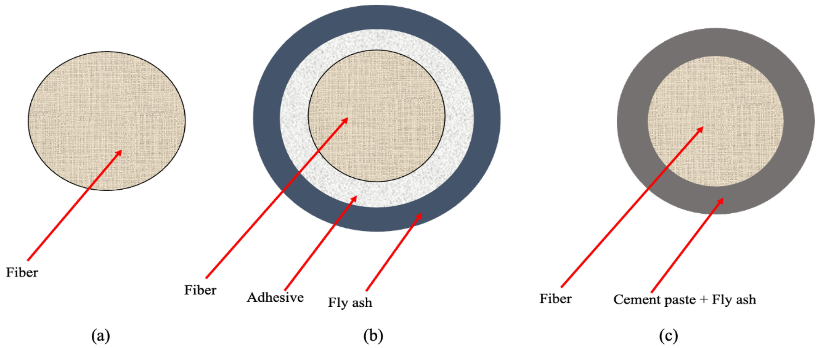
Table 3 represents seven mix designs incorporated in this study. The abbreviations for samples are adopted in such a way that COPP and COCF are samples with non-coated polypropylene and carbon fibers, CCF and CPP refer to adhesive-coated carbon fiber and polypropylene fiber and CFA and PFA refer to the carbon fiber and polypropylene fiber-reinforced samples which were coated using cement and fly ash. HYB is samples with both adhesive-coated CF and PP. Two methods of coating, as shown in Figure 1, were applied in this test. The first method was an attempt to physically adhere FA to fiber using a small portion of cement and water as the paste material and the second attempt was by the help of an adhesive chemical admixture. Last column in Table 3 shows coating method number as follows:
- 1
- Fibers, FA, cement, and water were thoroughly hand-mixed in a bowl and let the mixture rest for 3 h in ambient temperature. A 3-hour duration was chosen as a middle time between initial and final setting time of cement. The cement is losing its plasticity, but it is not completed yet.
- 2
- Fibers were coated with FA using an adhesive. In this procedure, fibers were first weighed and then they were put in a chamber with FA. Using an air compressor, they were fully dispersed by the force of air inside the chamber. Adhesive in the form of spray was used to adhere FA to fibers inside the chamber. Then fibers were taken out of the chamber, weighed and the difference between the initial and second weight was the weight of FA adhered to the fibers and was subtracted from required FA in the mix.
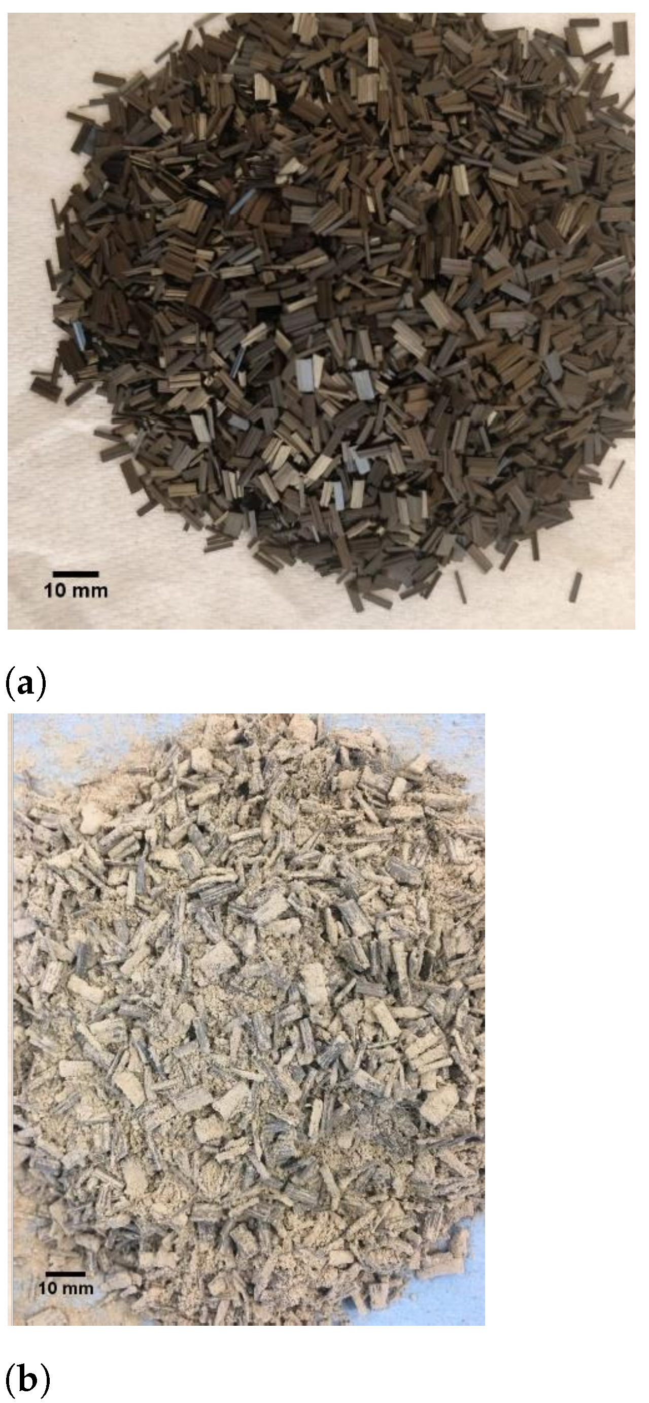
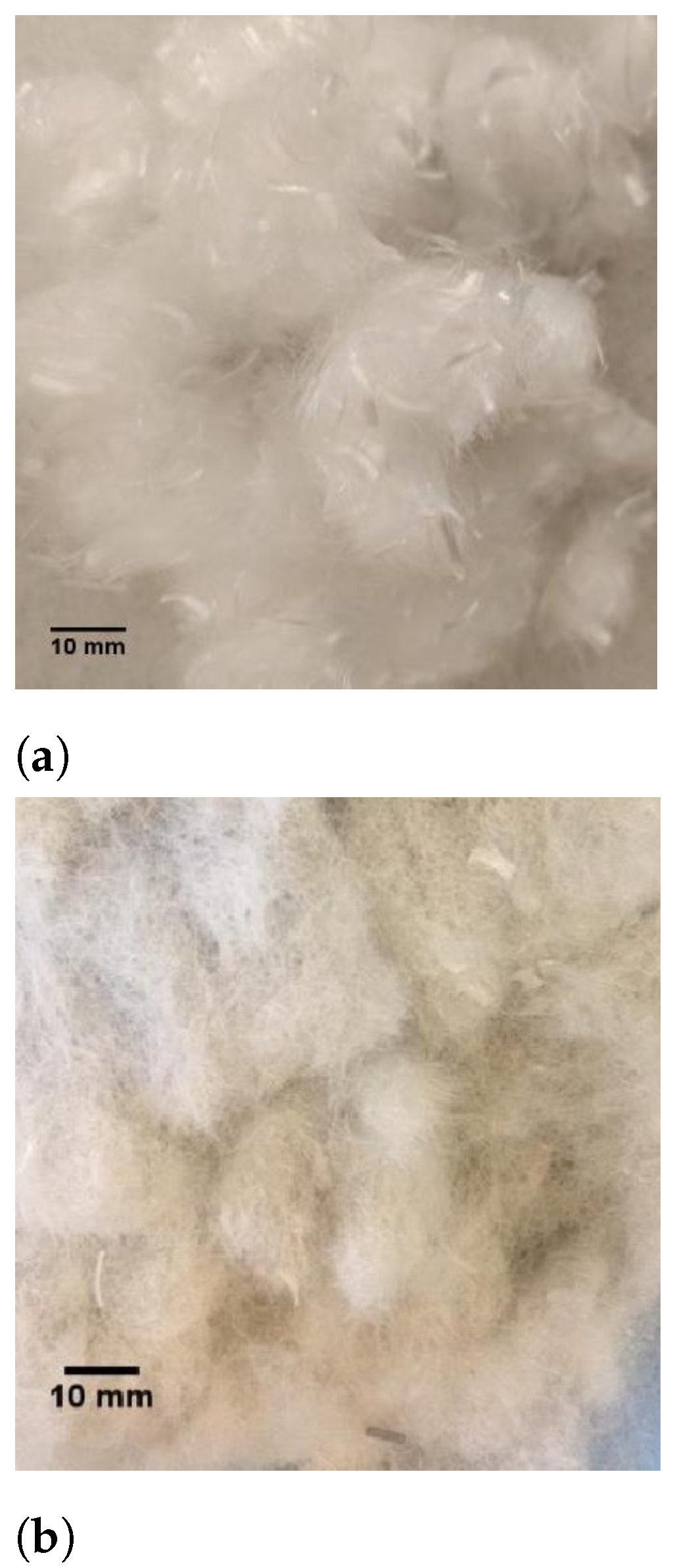
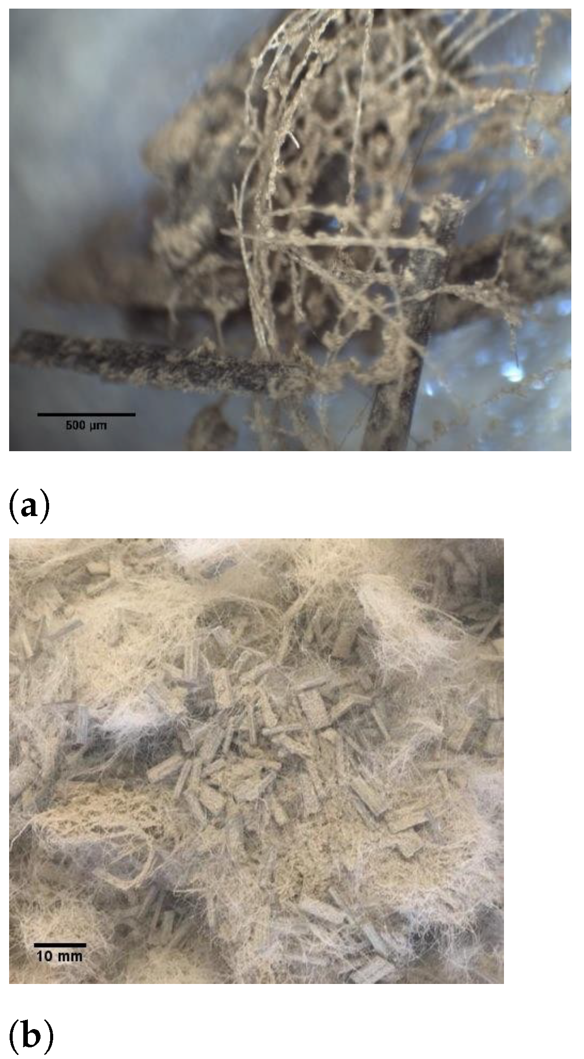
Figure 2 and Figure 3 show the appearance of PP fiber and carbon fiber before and after coating with adhesive and Figure 4 also shows hybrid PP and CF after being coated using adhesive. Mortar specimens made in accordance with ASTM C305 standard [31]. Samples were removed from molds after 24 h and were immersed in water tanks at a temperature of 23 ± 2 °C until the day of testing.
2.3. Testing Procedure and Equipment
A compressive strength test was performed on cube samples (50 × 50 × 50 mm) at 14 and 28 days age in accordance with ASTM C109 [32] using FORNEY F-650 compression machine. The testing machine was equipped with the appropriate compression platens and the loading rate was 900–1800 N/s.
Tensile strength test was performed according to ASTM C307 standard [33] on briquette samples (width and depth at waistline of briquette was 25 mm and length is 75 mm) at 14 and 28 days of age. PASCO® Testing Machine (MTM) with 1 mm/min crosshead loading rate was used to carry out the tensile test. The MTM had a built-in load cell capable of measuring up to 7100 newtons of force and an optical encoder module that was able measure the displacement of the load bar. MTM was coupled with PASCO® 550 Universal Interface to connect to the software.
Three-point flexural test was performed on prismatic samples with dimension (30 × 30 × 100 mm) at 28 days of curing according to ASTM C78 after 28 days of curing [34]. The load–deflection curve was obtained for each specimen tested. The deflection at the center of the specimens was measured using linear variable differential transformers (LVDT). The load was applied by an MTM testing machine and the loading rate was set at 1 mm/min. A minimum of three specimens for every mix was prepared for each test.
The flexural strength or modulus of rupture (MOR) of beams subjected to center-point bending test can be evaluated as follows:
MOR is the flexural strength (MPa); P is the ultimate load (N); L is the span of the test specimens (mm); b is the width of the test specimens (mm), and d is the height of the test specimens (mm).
According to Equation (2), the amount of absorbed energy can be determined by integrating the area under the load-displacement curve. In this research, the amount of flexural toughness was calculated at 3 (corresponding displacement with 3 times as high as the corresponding displacement of maximum load, ):
where E is the absorbed energy (N.mm), P is the force (N) and is the displacement (mm) in the middle of the flexural sample span.
Flexural toughness of beam sample is equal to the ratio of flexural toughness at 3 divided by the initial flexural toughness E where is the displacement at ultimate load.
Microstructural analysis was conducted on thin polished sections of fiber-reinforced mortar samples using scanning electron microscope (Hitachi Tabletop Scanning Electron Microscope) and Electron Dispersive X-Ray (EDX) analysis was performed using Hitachi S-4800 FESEM machine. Scanning Electron Microscopy (SEM) and elemental maps on fiber surface were used to identify changes in interfacial transition zone (ITZ) of fibers and cement matrix.
3. Results and Discussion
3.1. Compressive Strength
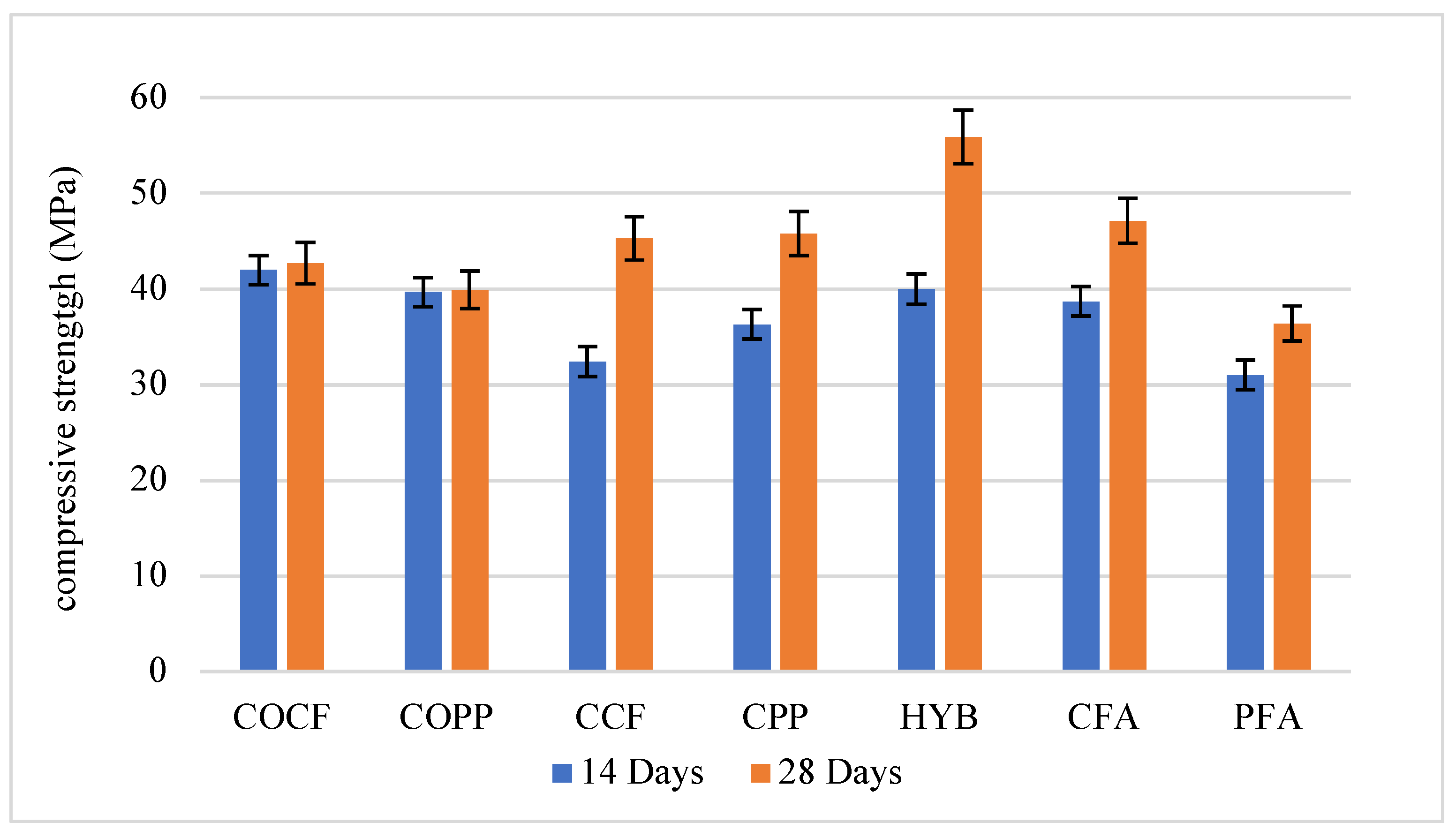
Figure 5 presents the results of compressive strength of samples at different ages. At 14 days of curing, all samples with coated fibers showed lower strength in comparison with non-coated fiber-reinforced samples. This is mainly due to the lower specific surface of FA (compared to other pozzolans such as silica fume or metakaolin) and not sufficient amount of calcium hydroxide (C-H) in early ages which results in lower early strength and additional strength at later ages. The contribution of silica fume and metakaolin to the strength of mortar was reported to start as early as 3 days and can be considered if early strength of composite needs to be taken into account [35]. Although FA is reported to be effective in later ages, the strength difference was marginal in some samples such as the hybrid and CCF samples. Coated polypropylene samples showed weaker strength compared to coated carbon-fiber-reinforced samples. However, after 28 days of curing, there was a significant improvement in strength of all coated samples. 0.5 and 1.7% improvement were calculated for non-coated PP and CF-reinforced samples respectively, while the amount was 39.8% and 26.2% for CCF and CPP samples and 21.7% and 17.4% for CFA and PFA samples. The degree of strength improvement in hybrid samples was 39.8% with around 60 MPa which makes it the superior mix design in compression. Compressive strength of concrete is highly dependent to the solidity of the bonds between particles. The more uniform the composite structure, the greater adhesion forces appear between its various components and the less porosity. Adding fibers to concrete makes the structure of the composite more heterogeneous and as a result, it causes a decrease in the strength as well as the formation of voids and pores in the areas between the fibers and cement paste. As a result, if the bonding within the concrete is improved by addition of additives, coating of fibers or other methods, the strength will increase. It is derived from the 28-day results that the bond between fiber and paste is significantly enhanced when fibers are coated regardless of the coating method. However, adhesive-coated samples showed a slightly better results compare to the other coating method.
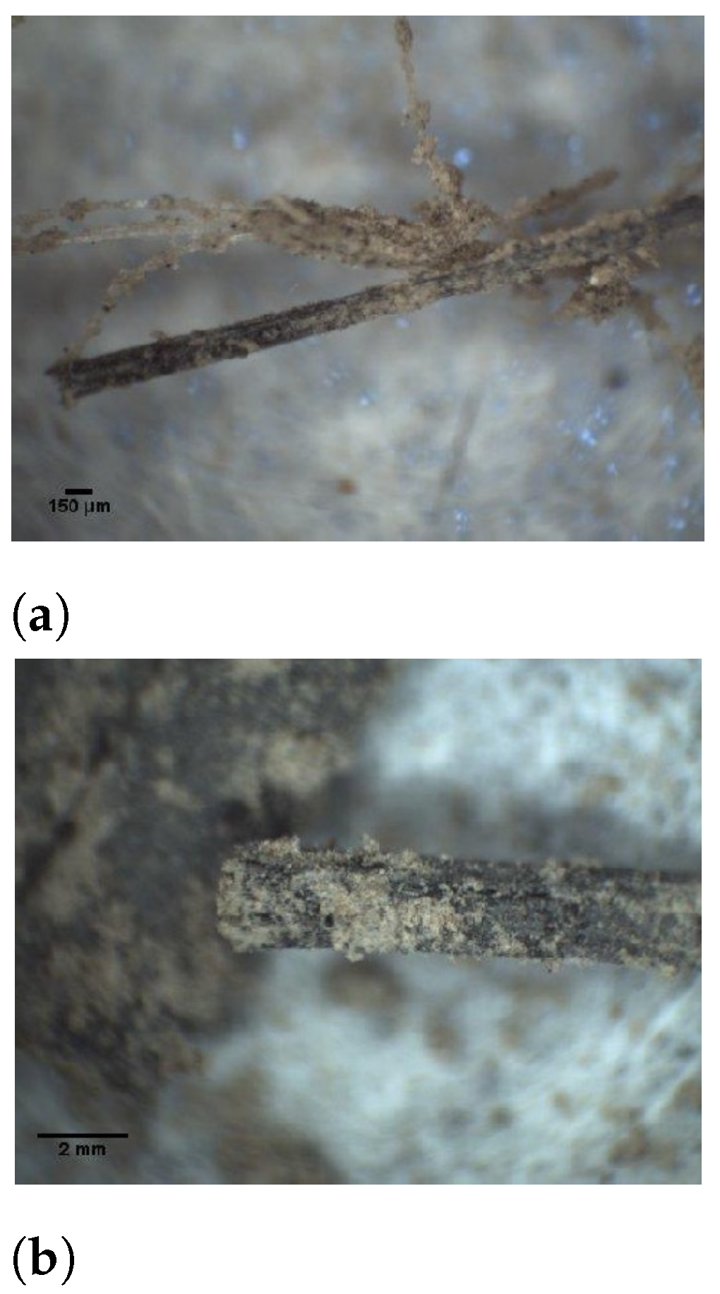
Figure 6 shows how FA is attached to carbon and polypropylene fiber. When the concentration of FA is higher around the fiber, it is expected to accelerate the hydration reaction around the fiber and as a result more hydration products are formed. The hydration products fill the porous areas between fiber and paste enhancing the bond and as a result increase the compressive strength of samples.
3.2. Tensile Strength
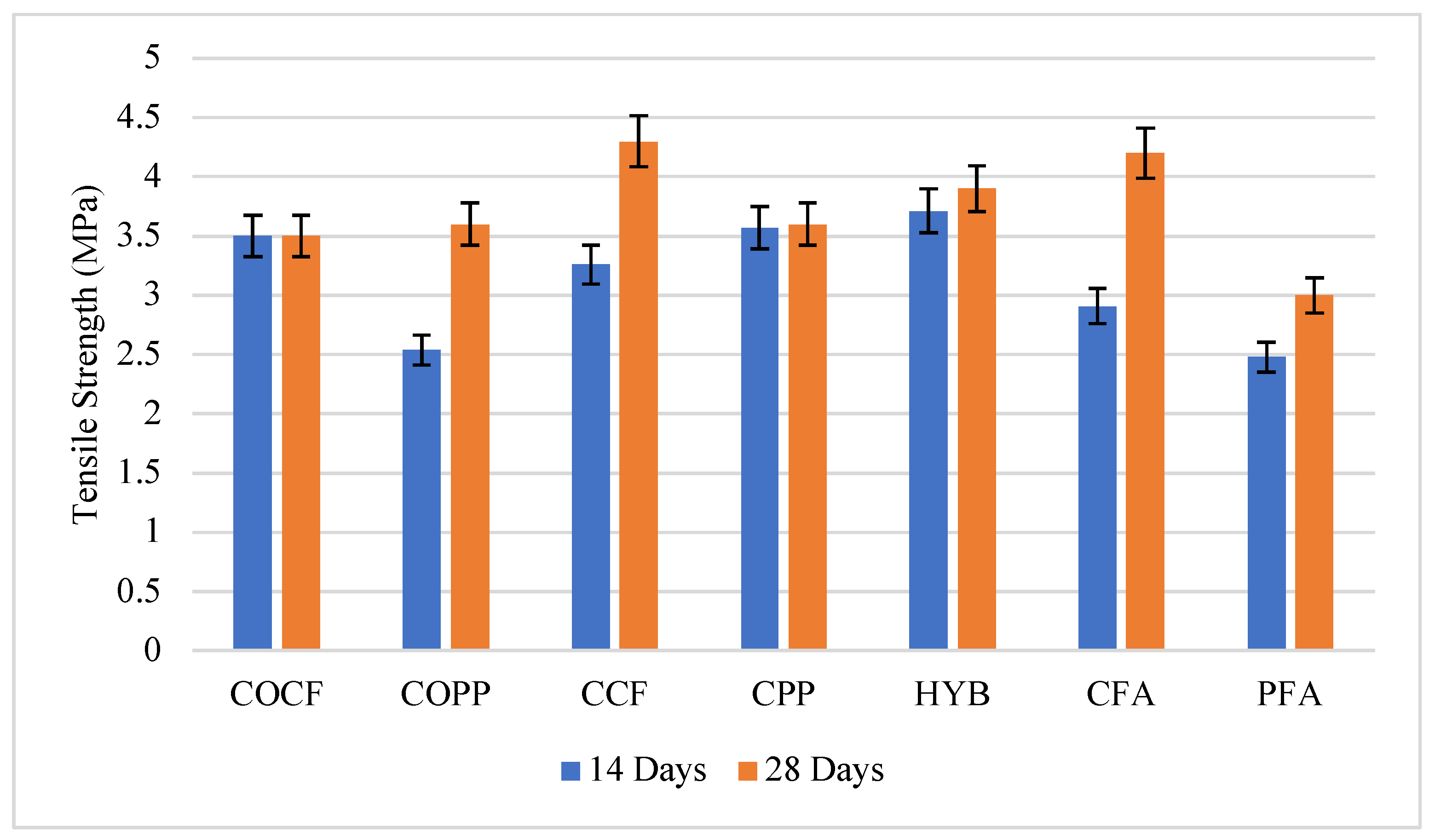
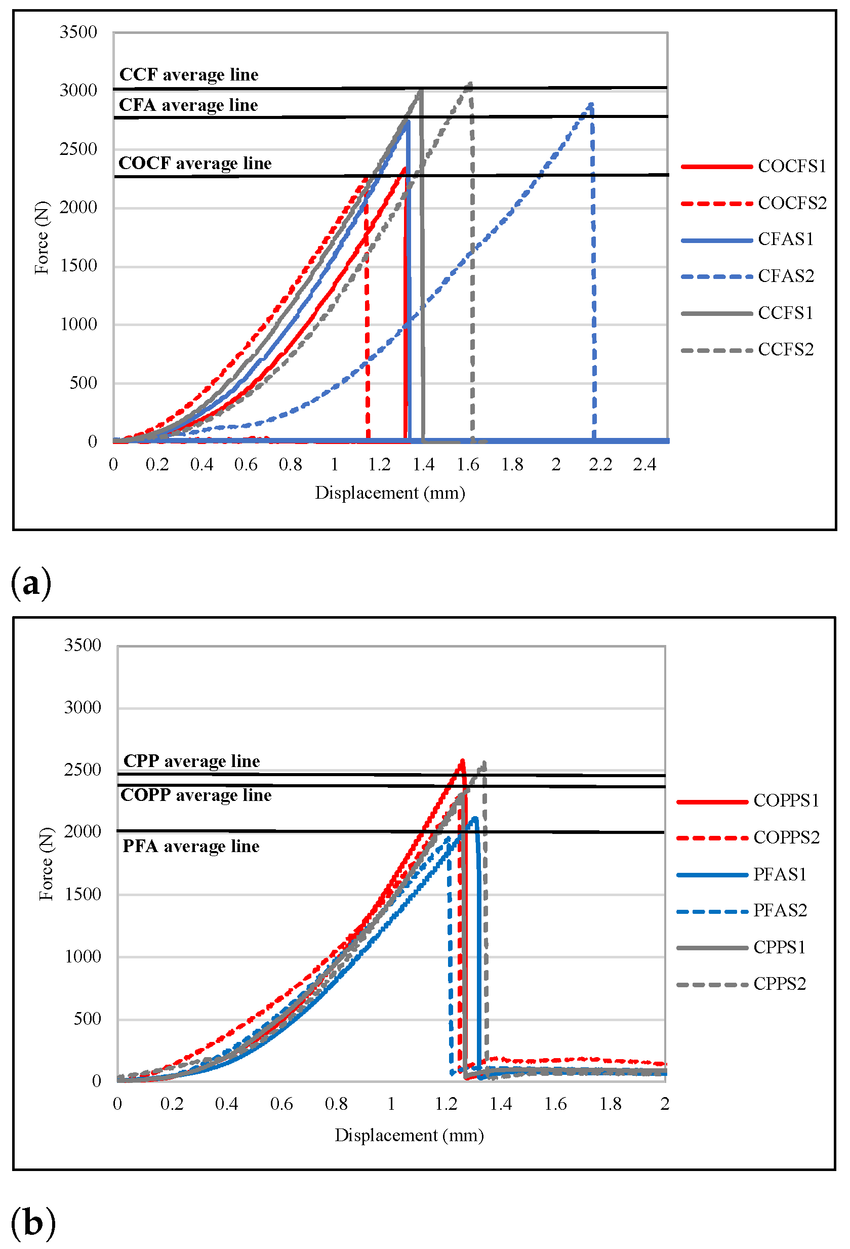
The results of the tensile strength test at 14 and 28 days of curing are presented in Figure 7 and the Force-displacement representative plots are given in Figure 8. The results showed that samples containing coated carbon fibers (samples made with both coating methods) experienced a substantial improvement at 28 days of curing when compared to non-coated carbon-fiber-reinforced samples, and 22.85 and 20% increase was reported in CCF and CFA, respectively. The reason the 28-day strength values are higher is that FA can participate in both early and late hydration reactions. However, Ettringite (calcium sulfoaluminate) is reported to be one of the main products of early hydration of FA [36] which does not add to the early age strength improvement of samples. Significant strength improvement of CCF and CFA proves the effectiveness of the two coating methods on tensile behavior of fiber-reinforced mortar samples. On the other hand, as is seen in Figure 8, all samples with 0.5% CF experienced a brittle fracture, while in samples reinforced with PP fibers, some post-crack response is observed. One purpose of adding fibers in concrete is to increase the energy absorption and load carrying capacity of cement composites after an initial crack and samples reinforced with PP are shown to behave more acceptable manner regarding to the post-crack behavior.
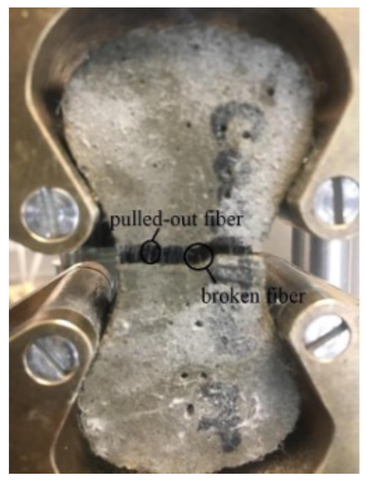
Samples with PP fibers generally showed lower tensile strength in comparison with carbon-fiber-reinforced samples. However, coating PP-reinforced samples with FA using adhesive has a positive effect on the tensile strength of samples, as the strengths of CPP samples at 14 and 28 days of curing are comparable with samples reinforced with carbon fibers. Lower strength in PP-reinforced samples and higher strength in CF-reinforced samples can be due to different modulus of elasticity of fibers. Fibers can be classified in two groups, fiber with high modulus of elasticity (known as hard intrusion fiber) and fibers with low modulus of elasticity (known as soft intrusion fibers) [16]. Hybrid samples coated with FA using adhesive also showed satisfactory results both at 14 and 28 days of curing (3.7 and 3.9 MPa), which demonstrates the positive effect of using hybrid fibers in mortar mixes. Concrete is intrinsically weak against tensile forces. An internal small crack in concrete can be easily propagated due to the inability of concrete to endure tensile strength. However, if the crack is confined locally by extending into another matrix adjacent to it, the extension of crack is retarded and results in higher tensile strength of concrete [37]. Addition of small length fibers can inhibit the propagation of cracks and leads to a better tensile strength. In Figure 9, presence of some fibers which are being pulled out is obvious. These fibers protect concrete from collapse which happens in normal mixes.
3.3. Modulus of Rupture (MOR)
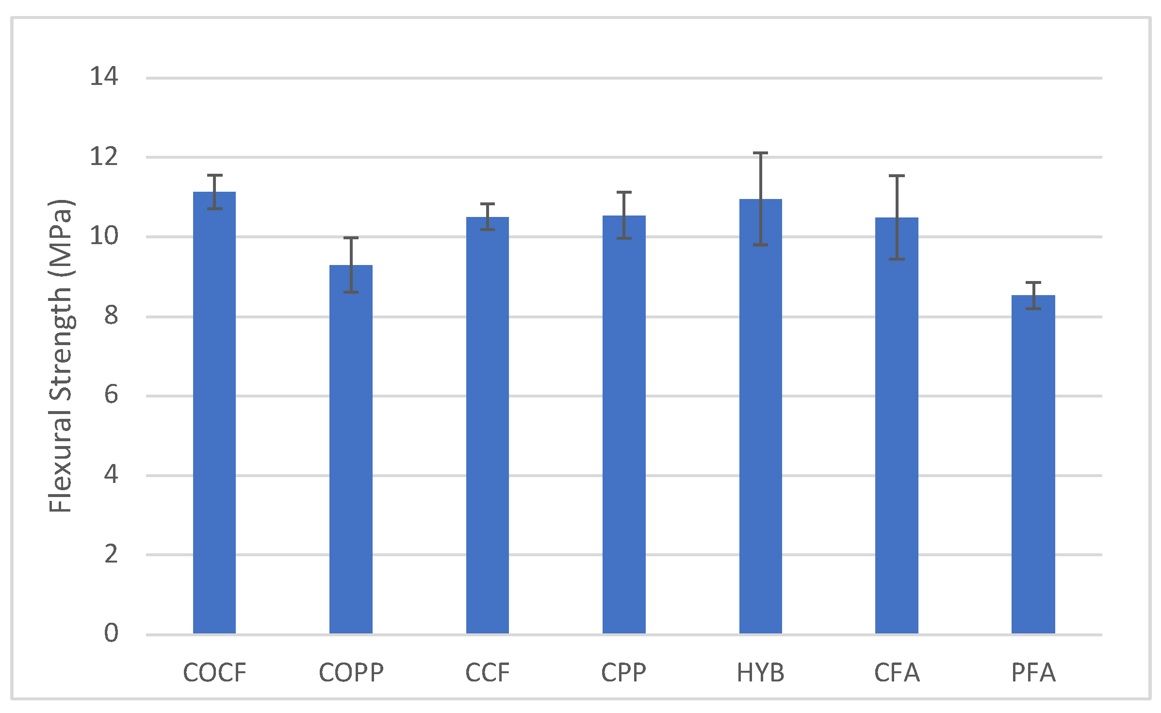
Flexural strength test measures the ability of concrete to resist deflection and cracking. Figure 10 presents the modulus of rupture of different samples under flexural test. It can be seen that incorporation of adhesive-coated polypropylene fibers can improve the flexural strength by 13.4% while the flexural strength of adhesive-coated carbon samples showed not much improvement. Although experiencing not much improvement in MOR, hybrid samples show acceptable results compared to COPP and COCF in post-crack behavior. The efficacy of using hybrid fibers, as approved in previous literature [8,15,17] can be explained in such a way that fibers with lower elastic modulus such as polypropylene fibers retard fast crack propagation into a slow controlled growth and hence more responsible for post-crack toughness. On the other hand, fibers with higher elastic modulus are more involved into improvement of flexural strength as well as pre-crack toughness and when the two types of fiber combined, the mix with hybrid fibers will benefit from both aforementioned behaviors.
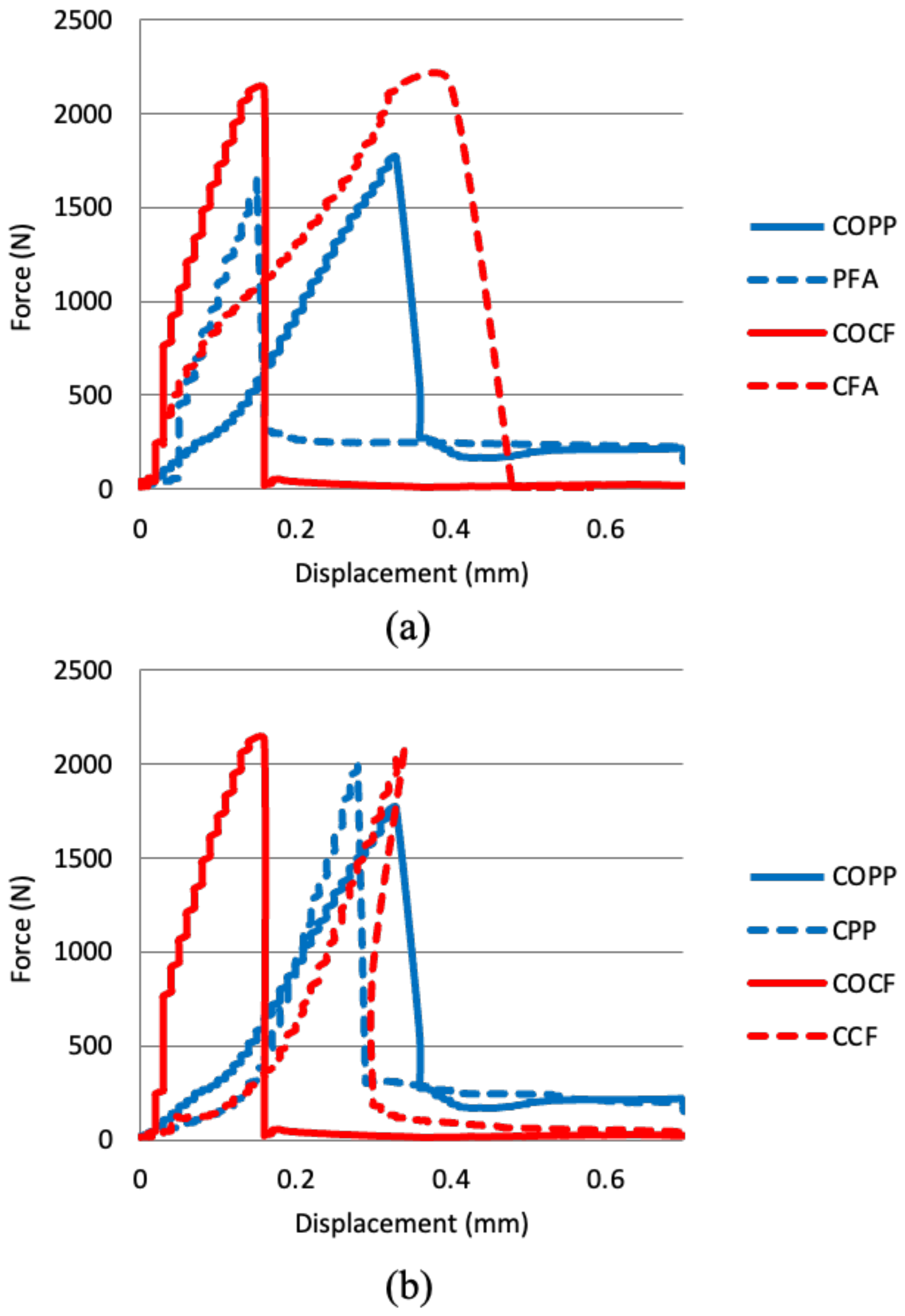
The energy absorbed during the flexural test and values are presented in Table 4 and Figure 11 is presented to show the failure pattern of different mixes. It is noteworthy to mention that each curve in the figure is a representative curve indicating a typical failure behavior of that specific mix. Despite the improvement in hybrid samples, the absorbed energy both before cracking and after cracking was declined substantially and this might be a consequence of the high dosage of fibers (0.25 PP and 0.5 % CF), which, in turn, means that the amount of coated fiber exceeds the optimum concentration. Considering both the flexural strength and toughness-related parameters, the results of the coating method #2 indicated a negative effect on MOR, pre-crack and post-crack of samples. This might be due to the change in pore structure of samples which necessitates the importance of investigating the pore structure of samples.
3.4. Scanning Electron Microscopy (SEM)
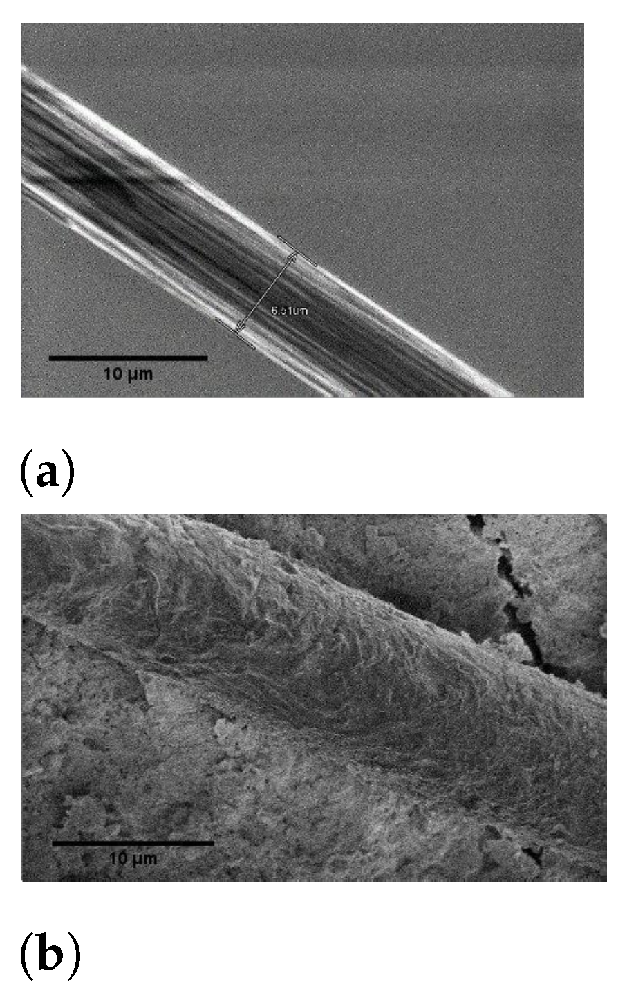
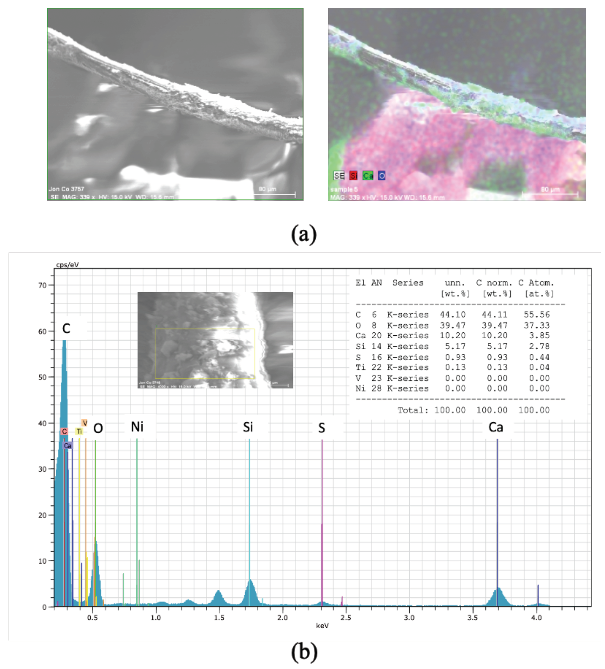
After completion of mechanical tests, fibers and mortar samples were chosen for further investigations and Using Scanning Electron Microscope and Energy-dispersive X-ray Spectroscopy (EDX), ITZ and elemental map of coated fibers were investigated. Figure 12 shows the SEM photos of non-coated carbon fiber and adhesive-coated carbon fiber in mortar. As is obvious, a uniform coating of FA seems to be present throughout the fiber and coating carbon fiber with FA has made the surface of the fiber rough which also improves the adherence between fiber and paste. Bruker Quantax System was used for X-ray spectroscopy to reveal the elements on the surface of the fiber in the mortar. As shown in Figure 13, The spectroscopy showed peaks of elements such as silicon, oxygen, and calcium on the surface of the fiber. The magnification level was set at 200× with an accelerating voltage of 15 kV and a working distance of 17.4 mm for the parent image. The elemental mapping revealed the positioning of silicon (primary component in FA) and calcium (primary component in cement) which basically demonstrates the presence of calcium silicate hydrate (C-S-H) on the surface of the fiber and the pore refinement effect of coating methods (due to the acceleration of pozzolanic reactions.
4. Conclusions
In this study, polypropylene and carbon fibers were coated using two methods of fiber coating, one method with using adhesive and another method with using cement and water as paste. Fibers were used as single and hybrid forms in mortar samples. Mechanical properties and interfacial microstructure of samples were investigated, and the results can be summarized as follows:
- 1
- At 14 days of curing, coated samples had lower or similar compressive strength in comparison with non-coated samples. However, the strength of coated samples was substantially improved at 28 days of curing and samples with coated carbon fibers and hybrid samples showed superior behavior in compression at 28 days of curing.
- 2
- Coating polypropylene fibers with fly ash using adhesive was an effective way to improve the tensile strength of PP-reinforced samples and both coating methods improved tensile strength of CF-reinforced samples substantially. Hybrid samples showed a slight increase in tensile strength at 14 and 28 days of curing.
- 3
- An improvement in MOR was observed when polypropylene fibers were coated with fly ash using adhesive. A marginal change in flexural strength was seen when CF was coated with both coating methods. The best flexural toughness (I5) was for the hybrid samples; however, the absorbed energy both before cracking and after cracking was declined substantially due to high dosage of fibers (0.25 PP and 0.5% CF), which, in turn, means that the amount of coated fiber exceeds the optimum concentration.
- 4
- Scanning Electron Microscopy (SEM) photos and Energy-Dispersive X-ray Analysis showed that FA is present throughout the surface of the fiber. The spectroscopy showed peaks of elements such as silicon, oxygen, and calcium on the surface of the fiber. The elemental mapping revealed the positioning of silicon (primary component in FA) and calcium (primary component in cement) which basically demonstrates the presence of hydration products on the surface of the fiber.
- 5
- Considering the efficacy of proposed fiber coating methods on static characterization and microstructure of composite and the importance of investigating the behavior of concrete under dynamic loading, further investigation is needed to assess the behavior of concrete under cyclic loading or to calculate the fracture mechanics parameters of concrete composites containing fibers coated with supplementary cementitious material.
Author Contributions
Methodology, M.M. and R.G.; formal analysis, M.M.; data curation, M.M.; writing–original draft preparation, M.M.; writing–review and editing, R.G. All authors have read and agreed to the published version of the manuscript.
Funding
This research was funded by Alberta Innovates (AI 2516).
Acknowledgments
The authors acknowledge the financial support received from Alberta Innovates. The technical advice offered by Axel Meisen and Paolo Bomben is greatly acknowledged. Contribution of Mitsubishi chemical and Euclid Chemical for the donation of the fibers used in this study and the support received from Boyu Wang and Rishabh Bajaj is also acknowledged.
Conflicts of Interest
The authors declare no conflict of interest.
References
- Banthia, N.; Gupta, R. Influence of polypropylene fiber geometry on plastic shrinkage cracking in concrete. Cem. Concr. Res. 2006, 36, 1263–1267. [Google Scholar] [CrossRef]
- Mohseni, E.; Khotbehsara, M.M.; Naseri, F.; Monazami, M.; Sarker, P. Polypropylene fiber reinforced cement mortars containing rice husk ash and nano-alumina. Constr. Build. Mater. 2016, 111, 429–439. [Google Scholar] [CrossRef]
- Afroughsabet, V.; Biolzi, L.; Ozbakkaloglu, T. High-performance fiber-reinforced concrete: A review. J. Mater. Sci. 2016, 51, 6517–6551. [Google Scholar] [CrossRef] [Green Version]
- Azhari, F.; Banthia, N. Cement-based sensors with carbon fibers and carbon nanotubes for piezoresistive sensing. Cem. Concr. Compos. 2012, 34, 866–873. [Google Scholar] [CrossRef]
- Chacko, R.M.; Banthia, N.; Mufti, A.A. Carbon-fiber-reinforced cement-based sensors. Can. J. Civ. Eng. 2007, 34, 284–290. [Google Scholar] [CrossRef] [Green Version]
- Chen, G.M.; He, Y.H.; Yang, H.; Chen, J.; Guo, Y. Compressive behavior of steel fiber reinforced recycled aggregate concrete after exposure to elevated temperatures. Constr. Build. Mater. 2014, 71, 1–15. [Google Scholar] [CrossRef] [Green Version]
- Konsta-Gdoutos, M.S.; Aza, C.A. Self sensing carbon nanotube (CNT) and nanofiber (CNF) cementitious composites for real time damage assessment in smart structures. Cem. Concr. Compos. 2014, 53, 162–169. [Google Scholar] [CrossRef]
- Tahmouresi, B.; Koushkbaghi, M.; Monazami, M.; Abbasi, M.T.; Nemati, P. Experimental and statistical analysis of hybrid-fiber-reinforced recycled aggregate concrete. Comput. Concr. 2019, 24, 193–206. [Google Scholar]
- El-Newihy, A.; Azarsa, P.; Gupta, R.; Biparva, A. Effect of polypropylene fibers on self-healing and dynamic modulus of elasticity recovery of fiber reinforced concrete. Fibers 2018, 6, 9. [Google Scholar] [CrossRef] [Green Version]
- Atiş, C.D.; Karahan, O. Properties of steel fiber reinforced fly ash concrete. Constr. Build. Mater. 2009, 23, 392–399. [Google Scholar] [CrossRef]
- Alhozaimy, A.; Soroushian, P.; Mirza, F. Mechanical properties of polypropylene fiber reinforced concrete and the effects of pozzolanic materials. Cem. Concr. Compos. 1996, 18, 85–92. [Google Scholar] [CrossRef]
- Park, S.; Lee, B.; Lim, Y. Experimental study on the engineering properties of carbon fiber reinforced cement composites. Cem. Concr. Res. 1991, 21, 589–600. [Google Scholar] [CrossRef]
- Ohama, Y.; Amano, M.; Endo, M. Properties of carbon fiber reinforced cement with silica fume. Concr. Int. 1985, 7, 58–62. [Google Scholar]
- Caggiano, A.; Gambarelli, S.; Martinelli, E.; Nisticò, N.; Pepe, M. Experimental characterization of the post-cracking response in hybrid steel/polypropylene fiber-reinforced concrete. Constr. Build. Mater. 2016, 125, 1035–1043. [Google Scholar] [CrossRef]
- Banthia, N.; Gupta, R. Hybrid fiber reinforced concrete (HyFRC): Fiber synergy in high strength matrices. Mater. Struct. 2004, 37, 707–716. [Google Scholar] [CrossRef]
- Parameswaran, V. Fibre-reinforced concrete: A versatile construction material. Build. Environ. 1991, 26, 301–305. [Google Scholar] [CrossRef]
- Yao, W.; Li, J.; Wu, K. Mechanical properties of hybrid fiber-reinforced concrete at low fiber volume fraction. Cem. Concr. Res. 2003, 33, 27–30. [Google Scholar] [CrossRef]
- Mindess, S.; Young, F.; Darwin, D. Concrete, 2nd ed.; Prentice Hall, Pearson Education, Inc.: Upper Saddle River, NJ, USA, 2003. [Google Scholar]
- Wang, X.H.; Jacobsen, S.; Lee, S.F.; He, J.Y.; Zhang, Z.L. Effect of silica fume, steel fiber and ITZ on the strength and fracture behavior of mortar. Mater. Struct. 2010, 43, 125–139. [Google Scholar] [CrossRef]
- Leemann, A.; Loser, R.; Münch, B. Influence of cement type on ITZ porosity and chloride resistance of self-compacting concrete. Cem. Concr. Compos. 2010, 32, 116–120. [Google Scholar] [CrossRef]
- Duan, P.; Shui, Z.; Chen, W.; Shen, C. Efficiency of mineral admixtures in concrete: Microstructure, compressive strength and stability of hydrate phases. Appl. Clay Sci. 2013, 83, 115–121. [Google Scholar] [CrossRef]
- Nili, M.; Ehsani, A. Investigating the effect of the cement paste and transition zone on strength development of concrete containing nanosilica and silica fume. Mater. Des. 2015, 75, 174–183. [Google Scholar] [CrossRef]
- Kabir, M.; Wang, H.; Lau, K.; Cardona, F. Chemical treatments on plant-based natural fibre reinforced polymer composites: An overview. Compos. Part B Eng. 2012, 43, 2883–2892. [Google Scholar] [CrossRef]
- Xie, J.; Xin, D.; Cao, H.; Wang, C.; Zhao, Y.; Yao, L.; Ji, F.; Qiu, Y. Improving carbon fiber adhesion to polyimide with atmospheric pressure plasma treatment. Surf. Coatings Technol. 2011, 206, 191–201. [Google Scholar] [CrossRef]
- Wang, S.; Chen, Z.H.; Ma, W.J.; Ma, Q.S. Influence of heat treatment on physical–chemical properties of PAN-based carbon fiber. Ceram. Int. 2006, 32, 291–295. [Google Scholar] [CrossRef]
- Di Maida, P.; Radi, E.; Sciancalepore, C.; Bondioli, F. Pullout behavior of polypropylene macro-synthetic fibers treated with nano-silica. Constr. Build. Mater. 2015, 82, 39–44. [Google Scholar] [CrossRef] [Green Version]
- Bajaj, R.; Wang, B.; Gupta, R. Characterization of Enhanced ITZ in Engineered Polypropylene Fibers for Bond Improvement. J. Compos. Sci. 2020, 4, 53. [Google Scholar] [CrossRef]
- Canadian Standards Association CSA A3000-13 Cementitious Materials Compendium. 2013. Available online: https://www.csagroup.org/store/product/CAN%25100CSA-A3000-13/ (accessed on 14 October 2021).
- ASTM. C150/C150M-17, Standard Specification for Portland Cement; American Society for Testing and Materials: West Conshohocken, PA, USA, 2017. [Google Scholar]
- ASTM C618. Standard Specification for Coal Fly Ash and Raw or Calcined Natural Pozzolan for Use in Concrete; American Society for Testing and Materials: West Conshohocken, PA, USA, 2003. [Google Scholar]
- ASTM. 305-14 Standard Practice for Mechanical Mixing of Hydraulic Cement Pastes and Mortars of Plastic Consistency ASTM C305-14; American Society for Testing and Materials: West Conshohocken, PA, USA, 2014. [Google Scholar]
- ASTM. Standard Test Method for Compressive Strength of Hydraulic Cement Mortars (Using 2-in. or [50-mm] Cube Specimens); American Society for Testing and Materials: West Conshohocken, PA, USA, 2013. [Google Scholar]
- ASTM C307-03. Standard Test Method for Tensile Strength of Chemical-Resistant Mortar, Grouts and Monolithic Surfacing; Committee C-1 on Cement; American Society for Testing and Materials: West Conshohocken, PA, USA, 2012. [Google Scholar]
- ASTM C78/C78M. Standard Test Method for Flexural Strength of Concrete (Using Simple Beam with Third-Point Loading); American Society for Testing and Materials: West Conshohocken, PA, USA, 2010. [Google Scholar]
- Mardani-Aghabaglou, A.; Sezer, G.İ.; Ramyar, K. Comparison of fly ash, silica fume and metakaolin from mechanical properties and durability performance of mortar mixtures view point. Constr. Build. Mater. 2014, 70, 17–25. [Google Scholar] [CrossRef]
- Berry, E.; Hemmings, R.; Cornelius, B. Mechanisms of hydration reactions in high volume fly ash pastes and mortars. Cem. Concr. Compos. 1990, 12, 253–261. [Google Scholar] [CrossRef]
- Romualdi, J.P.; Batson, G.B. Behavior of reinforced concrete beams with closely spaced reinforcement. J. Proc. 1963, 60, 775–790. [Google Scholar]
Figure 1.
Coating methods (a) Non-coated fiber (b) Fiber coated using adhesive (c) Fiber coated using fly ash paste.
Figure 1.
Coating methods (a) Non-coated fiber (b) Fiber coated using adhesive (c) Fiber coated using fly ash paste.

Figure 2.
Carbon fiber (a) before and (b) after coating by adhesive.

Figure 3.
Polypropylene fiber (a) before and (b) after coating by adhesive.

Figure 4.
Hybrid fibers (a) before and (b) after coating by adhesive.

Figure 5.
Compressive strength of samples after 14 and 28 days of curing.

Figure 6.
Coated (a) CF and PP and (b) CF.

Figure 7.
Tensile strength of samples after 14 and 28 days of curing.

Figure 8.
Force-displacement behavior of samples under tensile testing at 28 days of curing (a) carbon fiber reinforced mortar (b) polypropylene fiber reinforced mortar.
Figure 8.
Force-displacement behavior of samples under tensile testing at 28 days of curing (a) carbon fiber reinforced mortar (b) polypropylene fiber reinforced mortar.

Figure 9.
Coated PP-reinforced mortar under tension.

Figure 10.
Flexural strength of samples at 28 days of curing.

Figure 11.
Force-displacement behavior of samples under three-point bending test (a) samples coated using adhesive (b) samples physically coated with FA.
Figure 11.
Force-displacement behavior of samples under three-point bending test (a) samples coated using adhesive (b) samples physically coated with FA.

Figure 12.
SEM images of (a) non-coated CF (b) adhesive-coated CF.

Figure 13.
EDX analysis of the adhesive-coated (a) Carbon fiber (b) Polypropylene fiber.


Table 1.
Composition of adhesive.
| Ingredient | % by Weight |
|---|---|
| Acetone | 20–30 |
| Non-volatile components (N.J.T.S. Registry No. 04499600-6433P) | 20–30 |
| Propane | 15–25 |
| Cyclohexane | 10–20 |
| Petroleum distillates | 10–20 |
| Hexane | < 0.5 |
Table 2.
Mechanical and physical properties of fibers.
| Type | Length | Filament Diameter | Specific Gravity | Elastic Modulus | Tensile Strength |
|---|---|---|---|---|---|
| mm | µm | GPa | MPa | ||
| Carbon | 6 | 6 | 1.8 | 234 | 4800 |
| Polypropylene | 6 | 25 | 0.91 | 7 | 300–450 |
Table 3.
Mix design of mortar samples.
| Code | Sand | Cement | Water | Fly ash | CF | PP | Coating Method |
|---|---|---|---|---|---|---|---|
| kg/m | kg/m | kg/m | kg/m | g/m | g/m | ||
| COCF | 1188 | 570 | 281 | 142 | 4500 | 0 | - |
| COPP | 1188 | 570 | 281 | 142 | 0 | 4500 | - |
| CCF | 1188 | 570 | 281 | 142 | 4500 | 0 | 2 |
| CPP | 1188 | 570 | 281 | 142 | 0 | 4500 | 2 |
| HYB | 1188 | 570 | 281 | 142 | 4500 | 2500 | 2 |
| CFA | 1188 | 570 | 281 | 142 | 4500 | 0 | 1 |
| PFA | 1188 | 570 | 281 | 142 | 0 | 4500 | 1 |
Table 4.
Mix design of mortar samples.
| Code | S.D. | ||||
|---|---|---|---|---|---|
| N.mm | N.mm | N.mm | |||
| COCFS1 | 0.26 | 347.60 | 90.77 | 1.1 | 0.096 |
| COCFS2 | 0.69 | 1176.40 | 85.88 | ||
| COCFS3 | 0.56 | 1000.44 | 141.93 | ||
| COPPS1 | 0.46 | 792.47 | 297.90 | 1.52 | 0.303 |
| COPPS2 | 0.39 | 436.99 | 381.38 | ||
| COPPS3 | 0.26 | 224.58 | 72.53 | ||
| CCFS1 | 0.58 | 928.55 | 84.46 | 1.32 | 0.232 |
| CCFS2 | 0.50 | 817.57 | 454.18 | ||
| CCFS3 | 0.53 | 673.00 | 222.13 | ||
| CPPS1 | 0.15 | 157.86 | 38.85 | 1.26 | 0.045 |
| CPPS2 | 0.40 | 629.65 | 139.89 | ||
| CPPS3 | 0.33 | 427.85 | 130.91 | ||
| HYBS1 | 0.26 | 346.29 | 146.23 | 1.41 | 0.026 |
| HYBS2 | 0.19 | 320.46 | 123.32 | ||
| HYBS3 | 0.22 | 352.10 | 153.4 | ||
| CFAS1 | 0.56 | 682.49 | 123.49 | 1.23 | 0.078 |
| CFAS2 | 0.32 | 465.82 | 89.30 | ||
| CFAS3 | 0.51 | 738.85 | 236.96 | ||
| PFAS1 | 0.15 | 155.07 | 43.01 | 1.22 | 0.059 |
| PFAS2 | 0.22 | 265.84 | 42.10 | ||
| PFAS3 | 0.22 | 230.27 | 51.57 |
Publisher’s Note: MDPI stays neutral with regard to jurisdictional claims in published maps and institutional affiliations. |
© 2021 by the authors. Licensee MDPI, Basel, Switzerland. This article is an open access article distributed under the terms and conditions of the Creative Commons Attribution (CC BY) license (https://creativecommons.org/licenses/by/4.0/).
Share and Cite
MDPI and ACS Style
Monazami, M.; Gupta, R. Influence of Polypropylene, Carbon and Hybrid Coated Fiber on the Interfacial Microstructure Development of Cementitious Composites. Fibers 2021, 9, 65. https://0-doi-org.brum.beds.ac.uk/10.3390/fib9110065
AMA Style
Monazami M, Gupta R. Influence of Polypropylene, Carbon and Hybrid Coated Fiber on the Interfacial Microstructure Development of Cementitious Composites. Fibers. 2021; 9(11):65. https://0-doi-org.brum.beds.ac.uk/10.3390/fib9110065
Chicago/Turabian StyleMonazami, Maryam, and Rishi Gupta. 2021. "Influence of Polypropylene, Carbon and Hybrid Coated Fiber on the Interfacial Microstructure Development of Cementitious Composites" Fibers 9, no. 11: 65. https://0-doi-org.brum.beds.ac.uk/10.3390/fib9110065
Note that from the first issue of 2016, this journal uses article numbers instead of page numbers. See further details here.