
Cyclic Response of Bolted and Hybrid Pultruded FRP Beam-Column Joints between I-Shaped Sections


1
School of Architecture, Computing and Engineering (ACE), University of East London, 4-6 University Way, Beckton, London E16 2RD, UK
2
Department of Civil Engineering, College of Engineering Trivandrum, Thiruvananthapuram 695016, India
*
Author to whom correspondence should be addressed.
Fibers 2021, 9(11), 66; https://0-doi-org.brum.beds.ac.uk/10.3390/fib9110066
Submission received: 19 September 2021
/
Revised: 21 October 2021
/
Accepted: 26 October 2021
/
Published: 28 October 2021
Abstract
:This paper presents cyclic behaviour of bolted and hybrid–combined bolted and bonded fibre reinforced polymer (FRP) beam-to-column joints between I-shaped members using steel and FRP cleats. Five full-scale cyclic tests are carried out to study moment-rotation behaviour, cyclic response, and failure patterns. The test parameters include position of cleat (flange or combined web and flange), fastening method (bolting or hybrid–combining bolting and bonding) and cleat material (steel or FRP). First two tests had bolted and hybrid joints with steel flange and web double angles. Next two tests had the same joint detailing but with no web cleats. Last test used bolted joint only with FRP web and flange cleats. Three failure modes were observed: shear-out failure of the beam’s bolted zone, adhesive debonding with shear-out failure and delamination cracking. Cyclic performance of the joints was assessed by hysteresis moment-rotation curves and accumulated dissipated energy. Hybrid joints showed the best overall cyclic performance with accumulated dissipated energy about 75% higher than the bolted joints. Bolted joints with FRP cleats exhibited the worst cyclic performance. Flange cleated joints showed similar performance to web and flange cleated joints.
1. Introduction
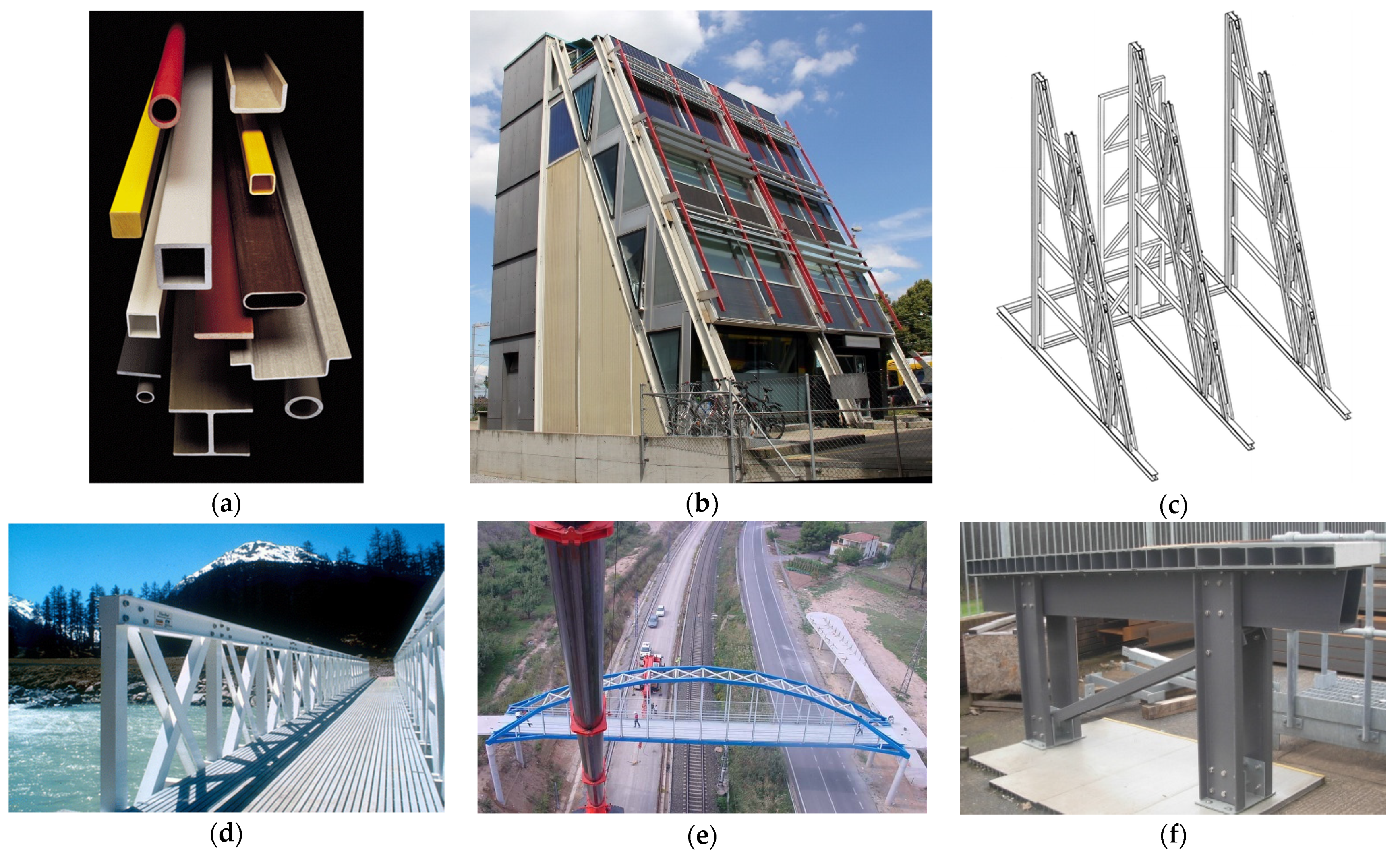
Fibre reinforced polymer (FRP) materials have desirable properties for structural engineering applications. High strength to weight ratio, electromagnetic transparency, lightweight and fast deployability, chemical and corrosion resistance, durability, formability and sustainability are some of the benefits of FRP. There are three main types of FRP shapes in structural engineering applications—pultruded glass fibre reinforced polymer profiles, FRP rebars and FRP strengthening systems. Pultruded FRPs are common in All-FRP structures. The standard shapes include I, H, L and tubular sections, as shown in Figure 1a. Typical applications include railway platforms, water and wastewater treatment plants, food and chemical processing plants, cooling towers and footbridges [1,2,3,4,5,6,7,8]. FRP composites have also been used in buildings. A FRP 15 m tall five-storey Eyecatcher building was constructed in Basel, Switzerland in 1998, see Figure 1b,c [9]. Other application of pultruded fibre reinforced polymer profiles in buildings and bridges are shown in Figure 1a–f. FRPs have also been used in repair and rehabilitation of existing structures [10,11]. The focus of this paper is on joints between pultruded FRP I-section profiles. FRP composites consist of high-strength carbon or glass fibres in a polyester or vinylester resin. FRP is a heterogenous material with properties in transvers direction about one-third of the longitudinal values. Being low stiffness material, design of FRP structures is governed by serviceability instead of ultimate resistance [12,13,14,15,16].
The design guidelines available for response of FRP beam-to-column joints are very limited [19]. Past research is mainly concentrated on moment-rotation response of FRP beam-to-column joints subjected to monotonic loading only [12,14,15,16,20,21,22,23,24,25,26,27]. The research on cyclic performance of FRP beam-column joints is scarce; only few papers exist [7,28,29,30,31,32,33,34,35,36,37,38]. And those too are focussed on development of connection components, such as cuff, sleeve or universal connector rather than the cyclic behaviour. Most the papers are related to joints between tubular sections. More research is needed on cyclic performance of FRP beam-to-column for enhancing knowledge and understanding of FRP composites. The main objective of this paper is to study cyclic behaviour of PFRP beam-to-column joints using both bolted and hybrid joints–combined bolted and bonded. Full-scale physical tests are carried out on FRP beam-to-column joints in this paper.
Arguably, Bruneau and Walker [29] were the first to test cyclic response of rigid beam-column joints between I-shaped PFRP beams and columns. The joints had web and flange cleats with column stiffener plates. The parts were joined by bolts and epoxy adhesive. The test configuration was very simplistic for cyclic testing. The specimen had to be inverted after each compression half cycle for applying tension load to complete the cycle. Apparently, the jack could only apply compressive load. This was the reason for only two cycles applied. The energy dissipation, one of the key performance indicators of the joints subjected to cyclic loading, was not measured. The inherent weakness of web-flange junction of PFRP profiles limited the ultimate moment capacity of the joint to only 35% of the predicted capacity. The authors concluded that bonded-only joints could not utilise full potential of the material and steel-like joint detailing could be inefficient for use in FRP. They suggested altering FRP manufacturing process to improve seismic worthiness of PFRP joints.
To improve joint properties, Mosallam et al. [39] developed a “universal connector” (UC) to connect various PFRP profiles. It used FRP angle stiffened by the side gusset plates. Later, Mosallam [38] tested two beam-column joints using this connector under cyclic loading. One specimen was bolted-only and the other used combined bolting and bonding. Composite rods and nuts were used to connect UC to the FRP members. The rotational stiffness of bolted and bonded specimen was five times higher than bolted-only specimen. Both specimens showed low dissipated energy and no ductility with linear moment-rotation response. The small ductility shown in the testing was attributed to use of composite rods.
In continuation of the work by Smith et al. [36,37] and Singamsethi et al. [34], Carrion et al. [35] studied the cyclic response of frame joints using monolithic composite cuff connection and PFRP box profiles. The cuff connection was produced by vacuum assisted resin transfer molding (VARTM) manufacturing process. Only adhesive bonding was used to connect cuffs with box beams and columns. They concluded that out of three cuff thicknesses (3.20, 6.35, and 9.55 mm), 6.35 mm cuff performed best with a comparable moment capacity to that of the beam. Thicker cuffs exhibited brittle bond failure and thinner cuffs showed somewhat ductile behaviour. Like other past papers, the energy dissipation was not discussed in this paper too. The focus of this paper was on performance of cuff rather than cyclic response of the joint.
Zhang et al. [33] investigated the cyclic performance of bonded sleeve connection joining box PFRP members. The sleeve connector was produced by welding a steel tube to a steel endplate. The steel tube was bonded to the FRP box beam and the endplate was bolted to the FRP column. Three tests were conducted under cyclic loading by varying number of bolts and thickness of the endplate connecting the column. Three failure modes were observed: progressive cohesive failure at FRP beam-steel tube interface, rupture of the web-flange junction of the beams and yielding of steel endplate. The joint with thicker endplate exhibited higher stiffness, but lower ultimate moment and rotation capacity than the thinner endplate. Number of bolts showed only marginal effect on ultimate joint properties. The authors also developed FE model of the joint but did not consider progressive damage of FRP material.
Martins et al. [31,32,40] developed a beam-to-column sleeve connection system for pultruded FRP box profiles. First, the feasibility of the sleeve connection system using internal steel parts and bolts was studied in [40]. Double-lap shear tests were used to assess in-plane behaviour and monotonic beam-column joint tests to evaluate out-of-plane or prying forces’ response. The joints with bolts in flanges with large edge distances showed a pseudo-ductile behaviour. Second, the cyclic response of the beam-column joints at connection level was studied in [32]. Four tests were conducted with: one bolt in the webs, two bolts in the flanges, four bolts in the flanges and two bolts in the flanges with large edge distance. The test with one bolt in the webs showed the worst overall cyclic performance in terms of dissipated energy and residual stiffness. On the other hand, the tests with two bolts in flanges showed the best performance for both monotonic and cyclic loading. This test was chosen for their third paper [31], which assessed the monotonic and cyclic sway response of FRP frames with or without composite panel infill walls. The infill walls had significant influence on structural behaviour of the frame. The infilled frame showed improvement in strength, stiffness, and energy dissipation over unfilled frame. The authors [31,32] also conducted a very simple FE modelling, which matched well with their experiments.
Razaqpur et al. [7] studied the static, cyclic and fatigue behaviour of bonded and bolted beam-column joints. Square hollow FRP columns were connected to built-up FRP beams consisting of back-to-back channel sections. The main purpose of this paper was to confirm that adhesive joints performed better than bolted joints in strength and stiffness. Cyclic testing was more focussed on fatigue type of loading, 50% of failure load was applied in 1200 cycles. No hysteresis moment-rotation loops or dissipated energy for seismic performance were studied. As fatigue loading is more common in bridge engineering, conclusions from this work can be useful in FRP bridge applications instead of buildings.
Bonded sleeve connection system was also used, recently, by Qiu et al. [28] for splice connection between two PFRP hollow box sections. The sleeve unit comprised of steel hollow section with steel flange plate at one end. Each FRP square hollow section was bonded to the steel sleeve and steel flange plates were bolted. Three tests were conducted by varying coupling bond length (170 or 120 mm) and number of bolts (4 or 8). The authors also carried out numerical modelling using Tsai-Wu failure criterion for FRP, which matched reasonably well with their experiments. The author concluded that bolt arrangement had a greater effect on stiffness degradation than the bond length. The geometry of flange plates (i.e., thickness of plate and number of bolts) and FRP-steel bond length can be varied to achieve a desirable energy dissipation for better seismic performance of the joints.
Review of above papers suggests that the research on cyclic response of joints between FRP I-shaped sections is very limited [29,30]. More research is needed to study cyclic response of pultruded FRP joints for wider applicability of FRP composites in buildings and for design guidelines in building codes. The main objective of this paper is to assess the cyclic response of PFRP joints between I-shaped sections using both steel and FRP cleats. Five tests are performed to characterise joint properties, study cyclic response, and identify failure modes. First set of tests had bolted and hybrid joints with steel flange and web cleats. Second set had bolted and hybrid versions with steel flange cleats only. Last test used a bolted joint with FRP web and flange cleats. Joint properties are characterised, failure patterns identified, and cyclic hysteretic moment-rotation loops plotted.
2. Test Configuration and Loading Protocol
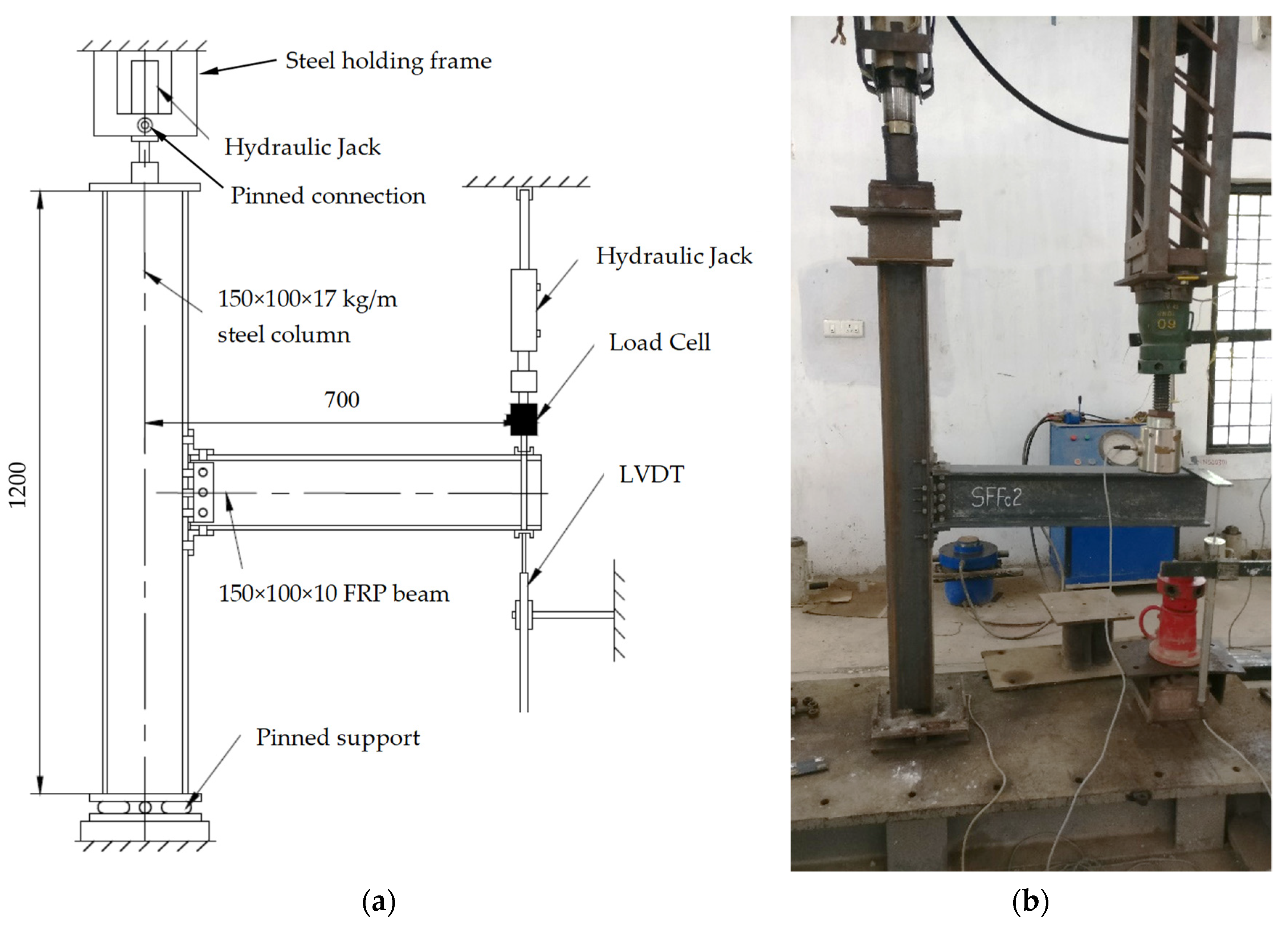
The testing uses a single-sided beam-to-column joint sub-assembly, as shown in Figure 2a. It represents exterior beam-to-column joints in a frame. The beam shape is 150 × 100 × 10 mm pultruded FRP wide-flange section, while the column is an ISWB 150 mm × 100 mm × 17 kg/m steel section. The main reason for using steel column in place of FRP is to avoid the tensile tearing failure in the column. This failure happens when the cleat material is steel and column material FRP. Since steel cleats do not deform under bending action, the failure is transferred to the FRP column. This is followed by large outward flexural deformation in the flanges of FRP column. The tensile tearing failure with outward flexural deformation of FRP columns flanges have been observed previously in [12,14,15]. The failure of a primary load carrying element (column) through tensile tearing of flanges could potentially be disastrous for FRP structures. As FRP cleats crack under prying action, fabricators normally prefer to use steel cleats, rather than FRP, to prevent moisture ingress in the joints for their durability performance [26].
The column has a pinned base that consists of two metal plates (200 × 200 × 10 mm) with steel rod (25 mm dia) welded to top plate and two elastomeric pads (200 × 80 × 10 mm) squeezed between them, as seen in Figure 2a. The top end of the column comprises a steel holding frame, mechanically pinned to the hydraulic jack at one end and fixed to the loading frame at the other. To house the column within the test frame, welded steel box sections with end plates are attached to the hydraulic jack and they rest directly on top of the column. Figure 2b shows a photograph of the beam-column joint sub-assembly within the test frame. The column and beam lengths are 1200 mm and 750 mm, respectively. The length from centreline of the beam loading point to the column centre is 700 mm. The vertical distance between centreline of the beam and the column base is 600 mm. All joints use the same size of cleats, 50 × 50 × 6 mm leg-angles. The cleats use either steel or FRP material. Material properties of steel and FRP are given in Table 1.
2.1. Joint Detailing and Configuration
Table 2 shows joint details, test parameters and failure modes for cyclic testing. The test labelling involves a four-letter format, followed by a number and a letter. First three capital letters show column, beam and cleat material (‘S’ for steel and ‘F’ for FRP. The fourth small letter indicates joint configuration, either ‘c’ for flange and web cleated or ‘tc’ for flange cleated only. The number can be ‘1’ for monotonic loading and ‘2’ for cyclic loading. Companion monotonic tests by the authors are reported in [12]. Both monotonic and cyclic tests had same joint detailing and member sizes. The last letter, ‘A’, is for adhesive bonding. Testing includes five full-scale beam-to-column joint specimens. SFSc2 had bolted joint with double web and flange (top and seat) steel cleats. SFSc2A used a hybrid joint combining bolting with bonding, with same detailing as SFSc2. SFStc2 and SFStc2A were identical to SFSc2 and SFSc2A, but without web cleats. SFFc2 used same configuration as SFSc2 with cleat material as FRP.
In the absence of any specific design guide for cyclic or seismic loading for FRP joints, the joint detailing is as per Eurocomp [41], IS 800 [42] and ASCE Pre-Standard [19]. The joints are either bolted or ‘hybrid’ combining both bolting and bonding. The testing uses two distinct joint details with either flange angles (top and seat) or flange and web angles combined. Flange cleated joints use two bolts per cleat leg and web cleated joints use three bolts. Grade 8.8 M12, with 12 mm diameter, threaded bolts are used as mechanical fasteners. Standard washers of size 25 × 3 mm were used. A bolt torque of 30 Nm representing the snug-tight condition is applied using an expression in [43]. Detailed calculations of bolt torque and bolt pre-tension force are given in Appendix A at the end of this paper. Snug-tight condition exhibits bolt tension enough to bring mating surfaces of the bolted parts into full contact [44]. Epoxy adhesive is used for adhesive bonding. Past research [29] suggests that epoxy results in a stronger joint than polyester adhesive.
Adhesive bonding uses epoxy resin AW 106 and hardener HV 953 U IN by Araldite® (Huntsman Corporation, The Woodlands, TX, USA). It is mixed in 1:0.9 ratio, as recommended by the supplier. Mating surfaces were sanded with 100 grit abrasive paper and cleaned using the acetone cleaning solvent to remove contaminants. The epoxy was applied to the bonding surfaces with a metal blade. The joints were then bolted ensuring no cavities. A layer of adhesive 0.05 to 0.10 mm thick will normally impart the greatest lap shear strength to a joint, as per the manufacturer’s guidelines. Therefore, the bond-line thickness did not affect the joint’s dimensions. Testing was carried out after 24 h of curing, as per the supplier’s guidelines.
2.2. Test Rig and Instrumentation
The testing was conducted in a steel loading frame with a hydraulic jack. The hydraulic actuator that loaded the beam had a capacity of 500 kN with a stroke of ±150 mm. The actuator had a load cell attached with a capacity of 50 kN and a resolution of ±0.02 kN. End displacements were measured by two 100 mm linear variable displacement transducers (LVDT) attached to the bottom and top beam flanges close to the loading point. The transducers had a resolution of ±0.01 mm. Another hydraulic jack, with a capacity of 250 kN and a travel of 150 mm, was used to apply the compressive load to the column.
A constant compression load of 20% of the column’s axial capacity was applied to the column before cyclic load on the beam. The purpose of this load was to hold the column in position and replicate a real-life situation, where columns support gravity loads. As the failure is likely to happen in either FRP cleats (SFFc2) or FRP beam’s bolted zone (all other tests), the compressive load on steel column will not affect the joint’s moment-rotation response. The joints are subjected to a moment by a vertical load applied through a hanger assembly near the free end of the beam. The hanger assembly contained a centrally placed ball bearing in a hemi-spherical steel socket for ensuring vertical alignment of the load. The load is applied at 700 mm from the centreline of the column leaving an overhang of 50 mm to the beam.
The joint rotation was worked out from measured displacements. The joint rotation is equal to vertical deflection at the load point divided by a fixed horizontal distance of 700 mm between the load point and the column centre. The centre point between two column flanges is assumed to be the column centre. The joint rotation is converted into milli-radians by multiplying it by 1000. This process of working out rotation is not as precise as using an inclinometer. However, the error percentage between rotations obtained from the inclinometer and a displacement transducer was only 5% in [14,15,16]. So, the rotations using a single vertical displacement transducer are accurate enough with an error percentage of 5%. Also, the column did not rotate due to vertical load equal to 20% of its plastic capacity. Because the bolts were tight-fitting without any clearance, any slip rotations due to bolt clearance holes were neglected too.
2.3. Loading Protocol
The cyclic load was applied to the end of the cantilever beam by controlling displacement at the load application point. Different cyclic loading protocols for testing steel structures (ATC-24 and SAC), wood structures (ISO and CUREE) and non-structural elements (FEMA-461 and FM-1950) have been used in the past [45]. This paper uses SAC protocol [46], which is based on deformation rather than yield loading point. The loading history in SAC protocol is based on nonlinear time-history dynamic response of steel moment-resisting frame subjected to seismic events. It uses inter-storey drift angle as a deformation parameter. In this paper, the inter-storey drift angle (total rotation), defined as displacement of loading point divided by distance between load point and centre of the column, is used to control the loading history.
The cyclic loading was applied by controlling displacement at the end of the beam. The loading history in Table 3 is defined to represent effects of earthquake and cause damage to the joint. It consists of stepwise symmetric displacement cycles. The specimens were loaded to 3 mm displacement in the first cycle and loaded to a negative value of 3 mm, then back to initial position of zero displacement, which completes a cycle. Next in each cycle, increments of 3 mm were used until 18 mm displacement. The increments were changed to 4 and 5 mm until 30 and 50 mm displacement, respectively. The increment was applied step by step until failure of joints. The specimens are not expected to withstand displacement in excess of 50 mm as indicated by corresponding monotonic testing in [12]. Yang and Kim [47] have used a similar loading history to test their steel beam-column joints.
3. Results and Discussion
This section reports moment-rotation hysteresis curves, cyclic performance using cumulative energy dissipation and failure modes. Monotonic moment-rotation curves from Qureshi et al. [12] are also presented for comparison.
3.1. Moment-Rotation Response
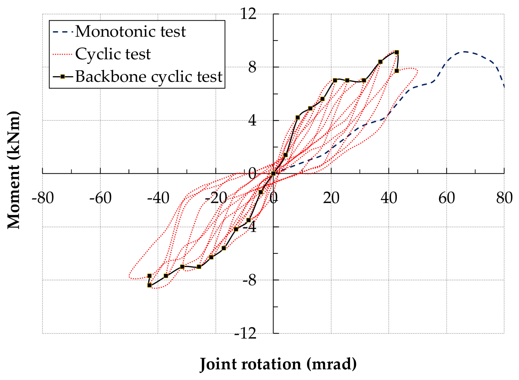
The behaviour of beam-to-column joint is studied through moment-rotation hysteresis curves. For comparison, moment-rotation curves from companion monotonic tests in [12] are given in Figure 3. Moment-rotation hysteresis curves for each specimen under cyclic loading are presented in Figure 4, Figure 5, Figure 6, Figure 7 and Figure 8. These figures also show companion monotonic moment-rotation response and cyclic backbone or reference skeleton curves. Backbone curves are produced by linking together peaks of full cycles. A full cycle comprises compression and tension half cycles. In Figure 4, Figure 5, Figure 6, Figure 7 and Figure 8, monotonic curves are shown by dashed lines, cyclic curves by dotted lines and backbone curves by solid lines with markers.
The moment-rotation properties can be categorised into initial, damage onset and maximum values. Table 4 shows a comparison of such properties for monotonic and cyclic tests. First failure or damage onset is the point on a moment-rotation curve, where either cracking causing fibre exposure happened or loud cracking noise was first heard. Apparently, it could be taken as synonymous to a yield point in steel structures. Initial moment, rotation and stiffness are denoted by Mi, ϕi and Si and damage properties are given by Mj, ϕj and Sj. Maximum moment is denoted by Mmax and rotation capacity at maximum moment is indicated by ϕmax.
Figure 3 presents the moment-rotation curves from companion monotonic tests conducted earlier by the authors [12]. The results showed that hybrid joints (bonded and bolted) exhibited 60% higher moment and stiffness than bolted only joints. Addition of web cleat to the flange cleated joint only enhanced stiffness without corresponding increase in the moment capacity. Use of steel cleats instead of FRP led to 50% increase in the moment capacity. Generally, hybrid joints exhibited higher rotational stiffness in moment-rotation plots than their bolted counterparts.
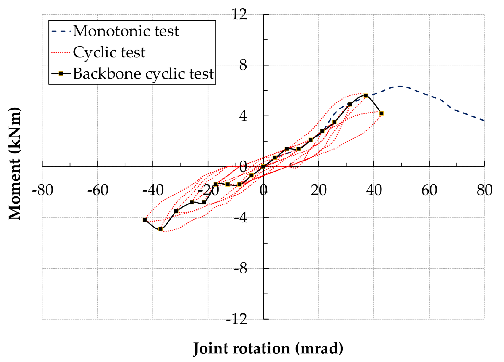
Figure 4 shows the moment-rotation response of the specimen SFSc2 (bolted joint with steel web and flange cleats). The backbone cyclic curve remained linear up to second loading cycle at Mi of 1.4 kNm and ϕi of 8.6 mrad with Si as 163 kNm/rad. Damage started to happen during 5th compression loading half cycle after 4th displacement increment (12 mm) with Mj = 2.1 kNm, ϕj = 17.1 mrad and Sj = 123 kNm/rad. Maximum moment and rotation happened at the end of 8th cycle at 5.6 kNm and 37.1 mrad. First failure or damage occurred in monotonic tests at a moment of 4.60 kNm and a rotation of 27.1 mrad with a stiffness of 170 kNm/rad. The damage in cyclic test happened much earlier than monotonic tests. The maximum properties in cyclic tests were also lower than monotonic tests.
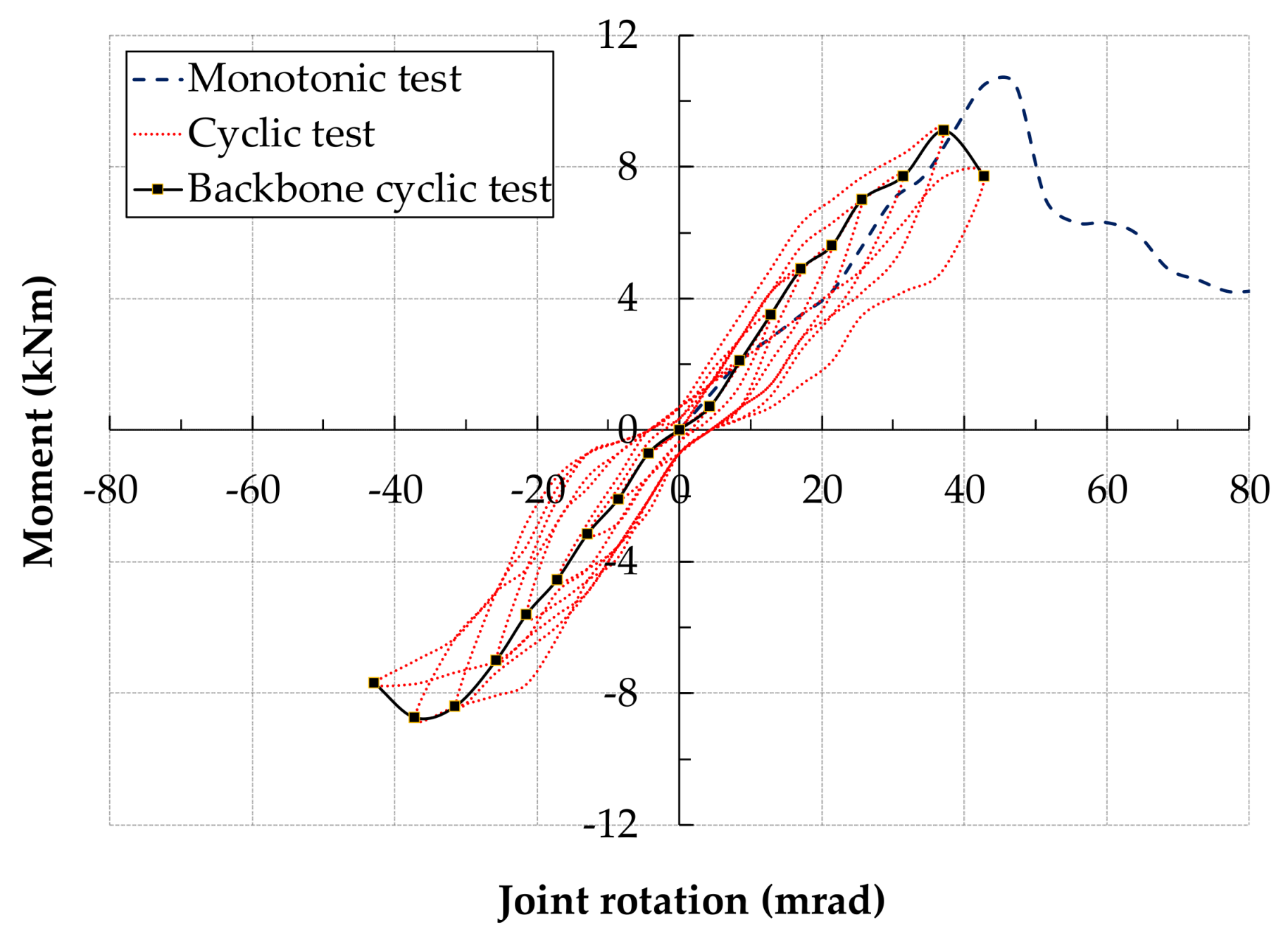
Figure 5 presents the moment versus rotation behaviour of the specimen SFSc2A (hybrid joint with steel web and flange cleats). The specimen SFSc2A had same joint details except mating surfaces were adhesively bonded in addition to bolting. The backbone moment-rotation curve remained linear until second loading cycle with moment of Mi of 2.1 kNm and ϕi of 8.6 mrad with Si as 245 kNm/rad. This time, first failure happened on the way to 5th tension half cycle at 4th displacement increment (12 mm).
Corresponding moment, rotation and stiffness for SFSc2A at damage onset were −5.25 kNm, −17.1 mrad and 306 kNm/rad, respectively. In contrast damage in monotonic tests happened much later at moment (7.0 kNm), rotation (30.0 mrad) and stiffness (233 kNm/rad). The specimen experienced the maximum moment (9.10 kNm) and rotation (37.1 mrad) at 8th cycle. Further loading resulted in drop in M-R curve.
The specimen SFStc2 comprised the same joint as SFSc2, but without web cleats. It only had bolted flange cleats and moment-rotation hysteresis loops are given in Figure 6. The specimen had same linear joint properties as SFSc2. The damage started at the end of 4th compression half cycle at moment 2.1 kNm and rotation 17.1 mrad and stiffness 123 kNm/rad. The initial and damage joint properties were the same as in the specimen SFSc2 with web and flange cleats. Addition of double web cleats to a flange-only cleated bolted joint did not affect the moment-rotation response, at least at damage onset. It withstood a maximum moment of 4.9 kNm with a rotation capacity of 42.9 mrad at 9th loading cycle.
Figure 7 shows moment-rotation response of a companion test SFStc2A to SFStc2, with adhesive bonding in addition to bolting. The backbone moment-rotation curve remained linear up to second cycle with initial moment (4.2 kNm), rotation (8.6 mrad) and stiffness (490 kNm/rad). First failure started during 5th compression loading half cycle after 4th displacement increment (12 mm) with Mj = 6.3 kNm, ϕj = 17.1 mrad and Sj = 368 kNm/rad. The initial and damage stiffness were far higher than corresponding monotonic stiffnesses. From 5th to 7th cycle, the moment stayed the same, 7 kNm, while rotation increased from 21.4 mrad to 31 mrad. Apparently, bonding failure happened at this point and the failure shifted to the beam. The specimen was able to take a maximum moment of 9.1 kNm with 42.9 mrad rotation at the end of 9th loading cycle. Any further loading resulted in drop in the moment carrying capacity.
Figure 8 presents moment-rotation response of SFFc2, the only specimen with FRP web and flange cleats. The backbone curve showed linear moment-rotation response until initial moment of 1.05 kNm and rotation of 8.6 mard, which led to initial stiffness of 123 kNm/rad. Damage started at the end of third compression half cycle, with moment reaching 1.75 kNm at a rotation of 12.86 mrad with corresponding stiffness of 136 kNm/rad. Damage in monotonic test started far later than cyclic test at moment level of 2.8 kNm with 30 mrad rotation resulting in 93 kNm/rad stiffness. The maximum moment attained was 3.5 kNm with a rotation capacity of 21.43 mrad at 5th loading cycle. This is clearly less than 4.2 kNm moment achieved in the monotonic test at a rotation of 42.9 mrad.
3.2. Cyclic Performance
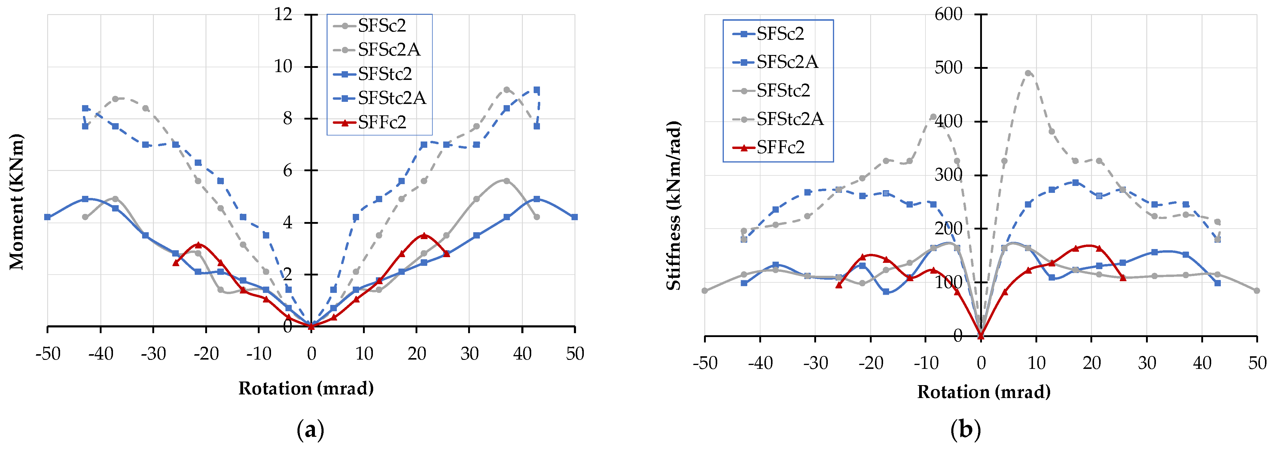
The cyclic behaviour is characterised by strength, stiffness, and energy dissipation. Figure 9 presents moment and stiffness evolution of each joint against number of loading cycles. Figure 10 shows the accumulated energy dissipation for each specimen. Martins et al. [30,32] assessed the moment and stiffness evolution by comparing the values at each cycle with yield moment and initial stiffness from monotonic tests. This helps to work out reserve capacity in terms of strength and stiffness at the completion of cyclic testing. They [30,32] applied the procedure for cyclic testing of steel structures to FRP joints using ECCS Manual [48]. The yield point was defined as end of linear elastic range in load-deflection curves.
Lack of ductility and absence of yield in FRPs is probably the biggest impediment to establishing initial and yield properties. While, theoretically, damage onset can be treated as a yield point for FRPs. But precisely when and where this damage happens remains the greatest challenge. At present, we rely on either visible appearance of cracking in FRP members/joints or first audible acoustic emissions. How about internal damage not noticeable to the naked eye? This introduces a big caveat in treating yield point and damage onset alike. Therefore, strength and stiffness progression in our paper are evaluated on their own without working out the reserve strength based on damage properties.
Firstly, the strength of the joint is evaluated in terms of moment capacity. Figure 9a presents the moment evolution at each positive and negative loading cycles. The moments are obtained from peak points in cyclic backbone curves in Figure 4, Figure 5, Figure 6, Figure 7 and Figure 8. The moment in positive and negative regions followed a similar pattern. Damage initiated at 4th or just before 5th cycle in all specimens except specimen with FRP cleats (SFFc2), where it happened at the 3rd cycle. Overall, the moment capacity of cyclic tests was similar to monotonic tests. Hybrid (bolted and bonded) joints generally attracted higher moments compared with bolted joints. The specimen with FRP cleats showed the lowest moment of all tests. The ratio of maximum over damage onset cyclic moment was about 2.5 for bolted joints and 1.5 for hybrid bonded and bolted joints. This indicates that adhesive bonding delays initiation of damage in FRP cleats and members.
Damage in cyclic tests started at a lower moment than monotonic tests, but this could be due to two reasons. First, there could be more damage in cyclic tests than monotonic tests due to positive and negative cycles. Second, the way the damage onset is established in the testing may not be entirely accurate as some damage cannot be visible to the bare eye or start of acoustic emissions/cracking noise can be missed. Comparison of web and flange cleated (SFSc2 and SFSc2A) and flange cleated only (SFStc2 and SFStc2A) show a very similar moment-rotation response in Figure 9a. No substantial gain in either moment or rotation capacity is observed by adding a web cleat to a flange-cleated joint.
Secondly, the stiffness of each joint is assessed at each rotation increment. The stiffness evolution of the cyclic tests is presented in Figure 9b. After first couple of cycles, the stiffness started to decrease in all specimens. Tests with hybrid joints using adhesive bonding exhibited higher stiffness compared with bolted only joints. Compressive and tensile cyclic regimes resulted in almost similar stiffness except SFStc2A specimen, where reversed cyclic loading had 20% lower stiffness than the positive loading half cycle.
Hybrid joints showed twice as much stiffness as bolted joints, regardless of joint detailing, as seen in Figure 9b. The specimen with FRP cleats, SFFc2 had slightly lower stiffness than then steel cleated, SFSc2, joint before damage onset. Once the damage started in the web cleats, the stiffness response of the FRP cleated joint (SFFc2) was almost identical to the steel cleated joints (SFSc2 and SFStc2). Since the damage always happened in FRP beam or cleats, the stiffness essentially remained the same after its initiation.
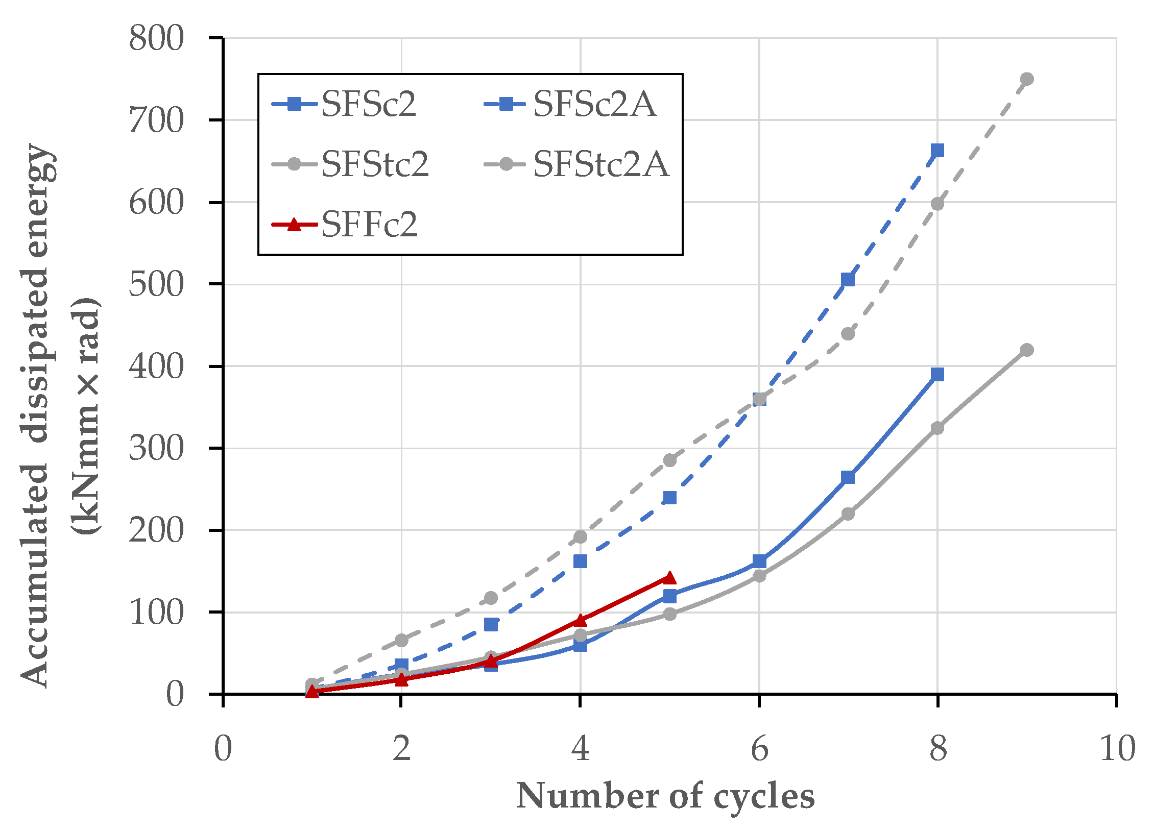
Thirdly, the cyclic performance of each specimen is evaluated by plotting the accumulated dissipated energy against number of cycles in Figure 10. The dissipated energy at each cycle is calculated as area enclosed by the moment-rotation hysteretic loop for each test. The accumulated dissipated energy is cumulative sum of each cycle. For example, 4th cycle is addition of dissipated energy from 1st to 4th cycles’ moment-rotation hysteresis curve. The hybrid joints (SFSc2A and SFStc2A) presented the best overall performance in terms of dissipated energy. The final accumulated dissipated energy for specimen with hybrid joints, SFSc2A and SFStc2A, was about 70% and 78% higher than bolted only specimens SFSc2 and SFStc2. The energy performance of web and flange cleated, and flange cleated joints was almost similar. This reinforces our conclusion earlier that use of web cleats is redundant; flange only cleated joint will perform equally well. FRP cleated joint performed poorly with final accumulated dissipated energy about half of the corresponding joint with steel cleats.
3.3. Design Recommendations
Lack of ductility and linear-elastic material behaviour are some of the main challenges in FRP design. Steel design is governed by Ultimate Limit State (ULS)–strength, providing a ULS factor of safety of 1.6. FRP design is controlled by Serviceability Limit State (SLS)–deflections/rotations; this generally gives a ULS factor of safety of about 5–10. So, the strength or resistance is not a major concern in FRP design. Mottram and Zheng [24] state that the rotation required for the serviceability limit state (SLS) for pinned joints is 12.8 mrad (corresponding to a midspan deflection of span/250). This SLS [41] is applied to design of FRP beams in simple braced frames.
The rotation at first failure or damage onset is important as it can be compared with serviceability design requirements given in [4,41]. First failure in FRP can be taken analogous to elastic limit or yielding in steel [49]. Visible cracking or acoustic emissions are signs of first cracking. If the serviceability requirements for rotation or midspan deflection are not met, the designer chooses the next deeper FRP section and different joint detailing to satisfy the serviceability demands. All joints in this paper met the severability requirements with joints rotations at first failure more than 12.8 mrad.
Design of pultruded FRP structures is governed by serviceability. Joint rotations, midspan deflections and lateral torsional instability are the key considerations in FRP design. Serviceability is also important from durability perspective. Cracking in FRP can lead to fibre exposure, which can cause environmental degradation of the exposed surfaces. So, pultruded FRP joints and members should be designed in such a way that the applied loading does not initiate cracking. Also, tubular profiles, such as rectangular hollow sections (RHS), can be used as beams to prevent lateral torsional instability.
3.4. Failure Modes
Failure modes are controlled by connection detailing and material strength. Steel is a homogeneous material being equally strong in all directions. FRP is nonhomogeneous with similar strength to steel in longitudinal direction. But its strength in transverse direction is about a third of its lengthwise value. Depending on joint detailing and material strength, three different failure patterns were observed, such as shear-out failure of beam’s bolted region, adhesive debonding with shear-out failure in beam and delamination cracking of cleat. These are explained in following sections.
3.4.1. Failure Modes of Web and Flange Cleated Joints (SFSc2, SFSc2A and SFFc2)
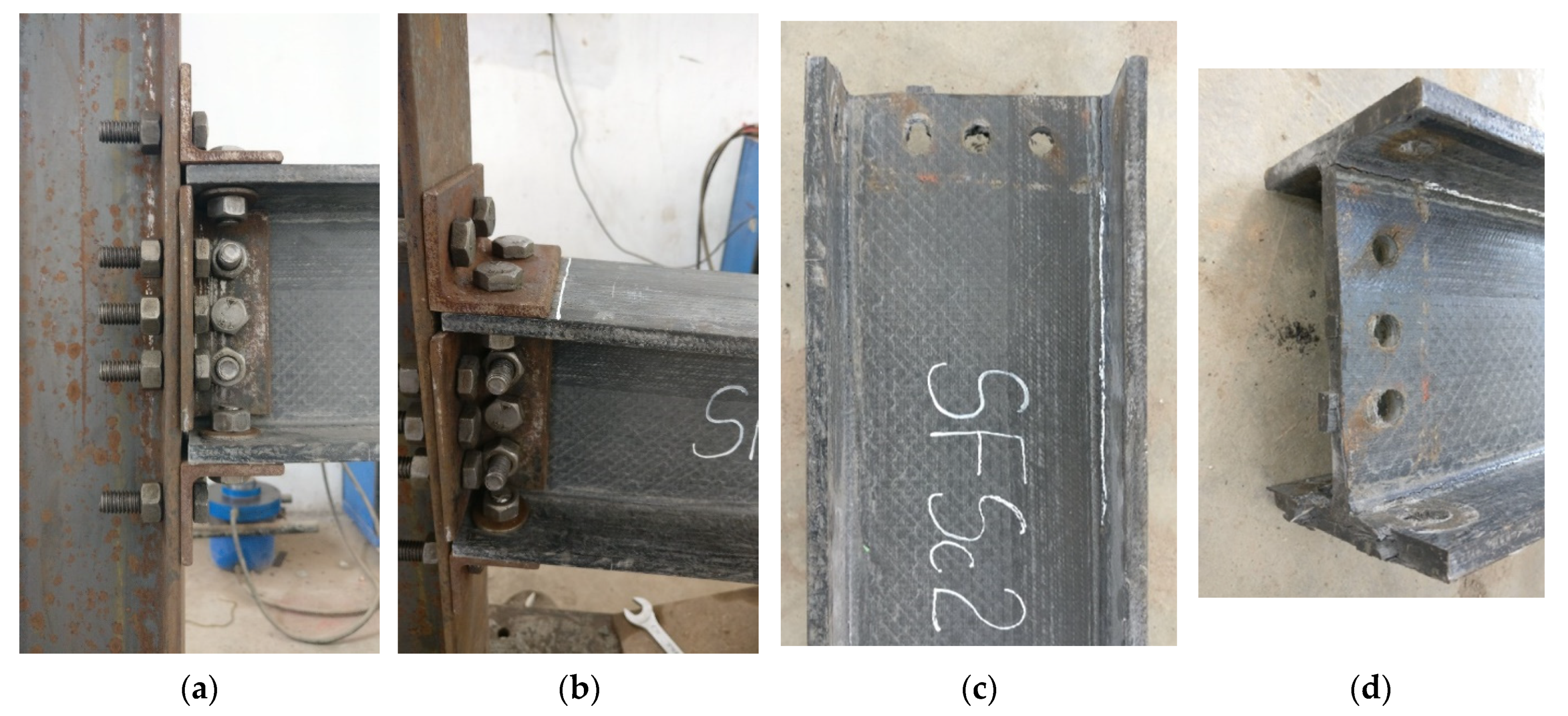
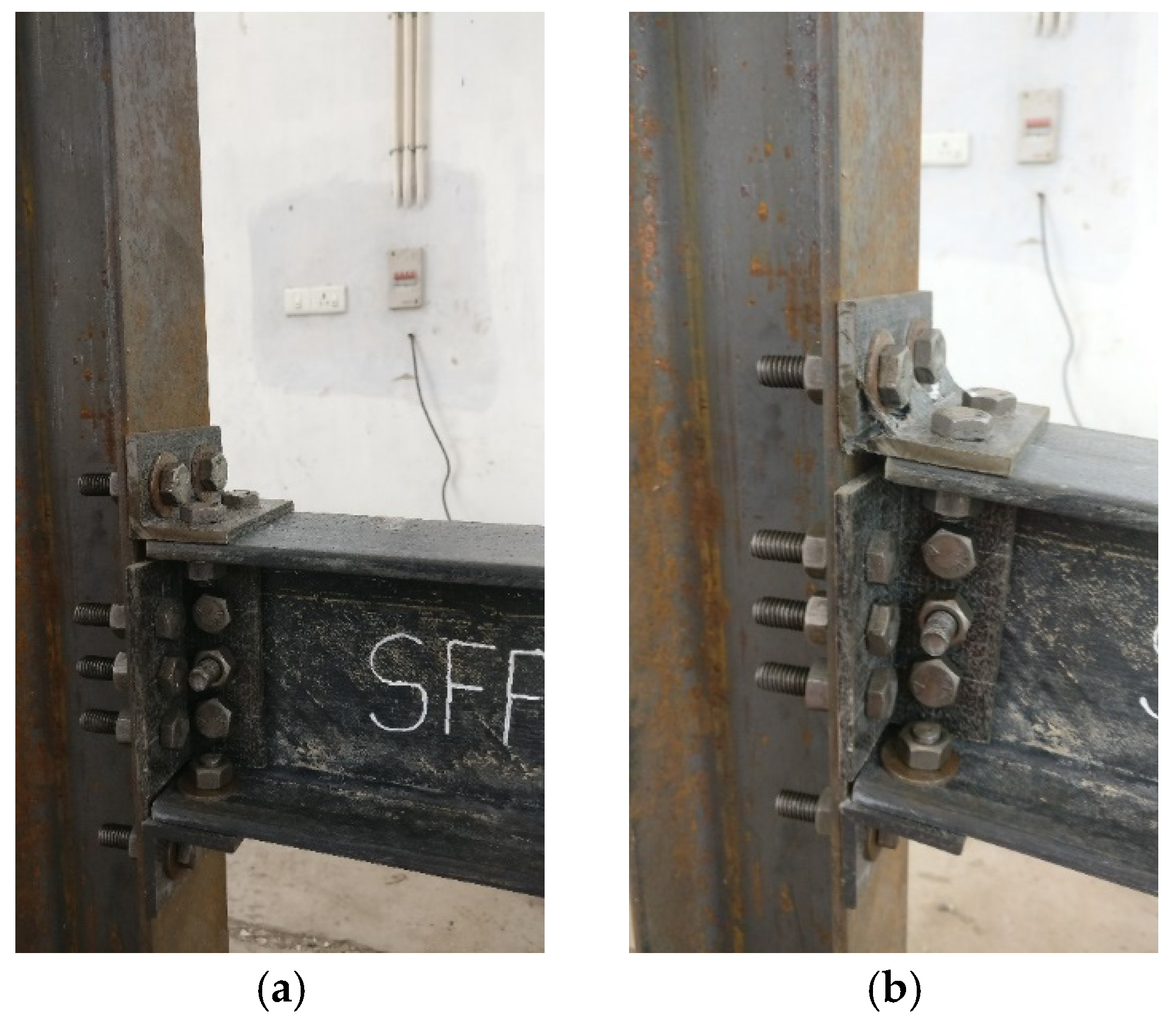
Flange and web cleated joints exhibited three distinct failure modes, depending on cleat material and use of adhesive bonding. These include shear-out failure of the beam’s bolted zone (SFSc2), Adhesive debonding with shear-out failure (SFSc2A) and delamination cracking at the root radius of cleats (SFFc2). Figure 11a,b show undeformed and deformed specimens of SFSc2. The damage onset was identified by visible cracking in the web-flange interface of the FRP beam along with audible acoustic emissions. Similar cracking was observed in the opposite web-flange interface of the beam in the successive negative and positive cycles. The final failure was due to the shear-out failure in the bolted region of FRP beam.
The shear-out failure happens when fibres are oriented mainly in the tension direction of the force or when the distance from bolt centreline to the free end of the beam is short. The shear-out was observed in the beam’s flange and web regions below the neutral axis after dismantling the joint, as shown in Figure 11c,d. The applied moment at the joint creates out-of-plane forces in the connected members. Due to cyclic loading, alternate prying and compressive forces cause shear-out failure in the beam flanges and web below neutral axis. The companion monotonic test also exhibited the same failure pattern.
For hybrid–adhesively bonded and bolted joint SFSc2A, the failure was due to adhesive debonding in the cleated region of the beam followed by shear-out failure in the bolted region of the FRP beam. Figure 12a,b show undeformed and deformed SFSc2A joint. The damage onset was identified by the visible cracking in the web-flange interface of the beam. The cracks progressed in the beam along with acoustic emissions in succeeding loading cycles. After reaching the ultimate moment capacity, the adhesive layer failed suddenly with visible separation of the steel cleat from the FRP beam, as seen in Figure 12c,d. The final failure was due to shear-out failure in bolted region of both flange and web of the beam. The adhesive bonding failed due to shear near the steel flange cleats by prying action. The shear-out failure in the beam was delayed by adhesive bonding.
For the FRP cleated joint SFFc2, the failure was due to delamination cracks at the root radius of FRP cleats. Figure 13 shows undeformed and deformed shape of the joint. Damage onset was manifested by hairline cracks at the root radius of FRP flange cleats. The cracks propagated from the root radius leading to delamination of the cleats. The prying action led to the cracks at the top and bottom flange cleats due to out-of-plane bending caused by the applied moment. No cracks were observed in the members. The failure was similar to monotonic loading. The delamination failure was also observed in the web cleats, which was observed after dismantling the joint.
3.4.2. Failure Modes of Flange Cleated Joints (SFStc2 and SFStc2A)
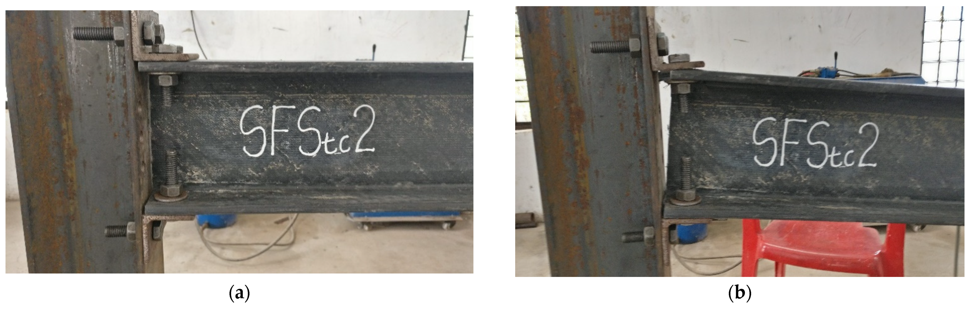
The failure modes observed in the joints were shear-out failure in SFStc2 and adhesive debonding followed by shear-out failure in SFStc2A. For the flange cleated joint SFStc2, the damage onset started in the beam flange, which was identified by slippage of tight-fitted bolts in the holes. This was accompanied by acoustic emissions too. In the subsequent loading cycles, the top and bottom flange of the beam experienced excessive shear-out leading to failure. Figure 14a,b show undeformed and deformed shape of the joint SFStc2. The applied moment at the joint creates out-of-plane forces in the connected members, which is taken by the flange cleats alone. The prying forces due to cyclic loading cause shear-out failure in the top and bottom flanges of the beam, whereas in the case of monotonic loading shear-out failure is visible in the top flange only.
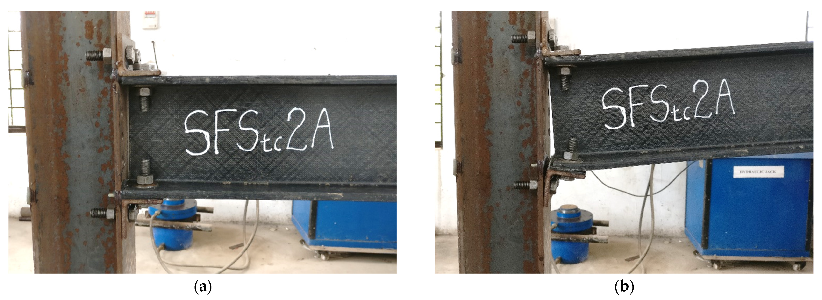
For SFStc2A, adhesive bonding delayed the cracking due to prying action at top and bottom cleats. The applied moment generates alternate prying and compressive forces on the top and bottom flanges. Since there are no other connecting elements, the prying action was more prominent in the flange-cleated joint than in the flange and web cleated joint. The delayed shear-out failure by adhesive bonding caused delamination cracking in the web-flange interface of the beam. The damage onset was identified by delamination cracking in the web-flange junction of the beam. Figure 15 shows undeformed and deformed SFStc2A joint. The failure was due to adhesive debonding followed by the shear-out failure of both beam flanges. The failure pattern was similar in monotonic loading with shear-out in top flange alone.
4. Concluding Remarks
Cyclic behaviour of pultruded FRP beam-to-column joints between I-shaped profiles is presented in this paper. Five full-scale joints are tested under cyclic loading. Monotonic test results from the companion paper [12] are also compared with cyclic test results. The test parameters include position of cleat (flange or flange and web), joining method (bolting or hybrid combining bolting and bonding) and cleat material (steel or FRP). Following conclusions can be drawn from this study:
- Depending on cleat material and joint detailing, three failure modes were observed: shear-out failure of beam’s bolted zone (bolted joints with steel cleats), adhesive debonding followed by shear-out failure of beam (hybrid joint–bolting and bonding combined with steel cleats) and delamination cracking at the root radius of cleats (bolted joints with FRP cleats).
- The ratio of maximum over damage onset cyclic moment was about 2.5 for bolted joints and 1.5 for hybrid bonded and bolted joints. This indicates that adhesive bonding delays initiation of damage within FRP cleats and members.
- Hybrid joints showed twice as much stiffness as bolted joints, regardless of joint detailing. Bonding does improve the connection stiffness, but without corresponding increase in the ultimate joint capacity.
- Adding a web cleat to a flange cleated joint resulted in no significant gain in strength, stiffness, and accumulated energy of the joint. This suggests that use of web cleat is redundant, a flange cleated joint on its own can achieve a comparable performance. However, the edge distance should be increased to avoid shear-out failure in the beam’s bolted region. Using flange and web cleats together may not be an economic or practical option, either web or flange cleat alone in a bolted joint achieves the same result.
- The hybrid joints with steel cleats showed the best overall performance in terms of dissipated energy. The accumulated dissipated energy of hybrid joints was about 75% higher than bolted joints. The dissipated energy performance of web and flange cleated, and flange cleated joints was almost similar. This shows that use of web cleats is redundant; flange-cleated joint only will perform equally well. The worst overall cyclic performance was shown by FRP cleated joint with accumulated dissipated energy only half of the equivalent joint with steel cleats.
- All joints subjected to both monotonic and cyclic loading met serviceability limit state (SLS) design requirements. The first failure/damage onset rotations were in excess of 12.8 mrad (corresponding to a midspan deflection of span/250)–SLS requirement in [41].
- Pultruded FRP structures should be designed to avoid cracking in FRP members or connecting components. The cracking can lead to environmental degradation of FRP structures.
Author Contributions
J.Q.: Data Curation, Formal analysis, Writing—Original Draft, Writing—Review & Editing. Y.N.: Conceptualization, Supervision, Funding acquisition. S.K.J.: Methodology, Investigation, Writing—Original Draft. All authors have read and agreed to the published version of the manuscript.
Funding
Centre for Engineering Research and Development (CERD), APJ Kerala Technological University (KTU) Trivandrum, Kerala, India (Research grant No: KTU/RESEARCH 3/1459/2017).
Institutional Review Board Statement
Not Applicable.
Informed Consent Statement
Not Applicable.
Data Availability Statement
Not Applicable.
Acknowledgments
The authors wish to thank Centre for Engineering Research and Development (CERD), APJ Kerala Technological University (KTU) Trivandrum, Kerala, India for funding this research project as a part of Research Seed Money.
Conflicts of Interest
The authors declare no conflict of interest.
Appendix A. Calculation of Bolt Torque and Bolt Pre-Tension Force
An acceptable formula relating bolt torque (T) to bolt tension (P) is:
where d is the diameter of the M12 bolt. Provenance to the formula is to be found in [43]. Note that the factor 0.2 can range as low as 0.01 for well-lubricated assemblies and can exceed 0.025 for dry or rusty fasteners.
T = 0.2dP,
Let us allow the maximum average compression strength (σc,max) under a washer to be 50 N/mm2. The paper by JT Mottram in [41] states, “so that the bearing pressure is no higher than one-third of the through-thickness crushing strength of the material and in no event higher than 68 N/mm2.”
Washer has an outer diameter (do) of 25 mm and an inner diameter (di) of 14 mm. Maximum compression force to be resisted by a washer is = 16.85 kN. This is also the maximum tension force (Pmax) in the bolt. The maximum torque (Tmax) that should be applied is given by Tmax = 0.2dPmax = 0.2 × 0.012 × 16,850 = 40.4 Nm.
This is (Tmax = 40.4 Nm) is the maximum bolt torque that can applied to tighten the bolts. As our intension was to bring the mating surfaces in full contact to represent the sung-fit condition, we reduced the bolt torque to 30 N.m. Therefore, the applied bolt pre-tension force is T = 0.2dP, P = T/0.2d = 30/(0.2 × 12) = 12.5 kN.
References
- Mottram, J.T.; Henderson, J. (Eds.) Fibre-Reinforced Polymer Bridges—Guidance for Designers; CIRIA publication C779; Construction Sector Group, Composites UK: London, UK, 2018; ISBN 9780860177944. [Google Scholar]
- Bank, L.C. Composites for Construction—Structural Design with FRP Materials; John Wiley & Sons: Hoboken, NJ, USA, 2006. [Google Scholar]
- Correia, J.R.; Bai, Y.; Keller, T. A review of the fire behaviour of pultruded GFRP structural profiles for civil engineering applications. Compos. Struct. 2015, 127, 267–287. [Google Scholar] [CrossRef]
- Fiberline Composites. Fiberline Design Manual; Fiberline Composites A/S: Kolding, Denmark, 2002. [Google Scholar]
- Strongwell. Strongwell Design Manual; Strongwell Corporation: Bristol, WV, USA, 2010. [Google Scholar]
- Creative Pultrusions. The New and Improved Pultex Pultrusion Design Manual; Creative Pultrusions Inc.: Alum Bank, PA, USA, 2004. [Google Scholar]
- Razaqpur, A.G.; Ascione, F.; Lamberti, M.; Spadea, S.; Malagic, M. GFRP hollow column to built-up beam adhesive connection: Mechanical behaviour under quasi-static, cyclic and fatigue loading. Compos. Struct. 2019, 224, 111069. [Google Scholar] [CrossRef]
- Goncalves, M.C.; Margarido, F. (Eds.) Materials for Construction and Civil Engineering, 1st ed.; Springer International Publishing: Cham, Switzerland, 2015; ISBN 978-3-319-08235-6. [Google Scholar]
- Keller, T. Towards Structural Forms for Composite Fibre Materials. Struct. Eng. Int. 1999, 9, 297–300. [Google Scholar] [CrossRef]
- Zhou, Y.; Guo, M.; Sui, L.; Xing, F.; Hu, B.; Huang, Z.; Yun, Y. Shear strength components of adjustable hybrid bonded CFRP shear-strengthened RC beams. Compos. Part B Eng. 2019, 163, 36–51. [Google Scholar] [CrossRef]
- Hu, B.; Zhou, Y.; Xing, F.; Sui, L.; Luo, M. Experimental and theoretical investigation on the hybrid CFRP-ECC flexural strengthening of RC beams with corroded longitudinal reinforcement. Eng. Struct. 2019, 200, 109717. [Google Scholar] [CrossRef]
- Qureshi, J.; Nadir, Y.; John, S.K. Bolted and bonded FRP beam-column joints with semi-rigid end conditions. Compos. Struct. 2020, 247, 112500. [Google Scholar] [CrossRef]
- Girão Coelho, A.M.; Mottram, J.T.; Harries, K.A. Bolted connections of pultruded GFRP: Implications of geometric characteristics on net section failure. Compos. Struct. 2015, 131, 878–884. [Google Scholar] [CrossRef] [Green Version]
- Qureshi, J.; Mottram, J.T. Response of beam-to-column web cleated joints for FRP pultruded members. J. Compos. Constr. 2014, 18, 04013039. [Google Scholar] [CrossRef]
- Qureshi, J.; Mottram, J.T. Behaviour of pultruded beam-to-column joints using steel web cleats. Thin-Walled Struct. 2013, 73, 48–56. [Google Scholar] [CrossRef]
- Qureshi, J.; Mottram, J.T. Moment-rotation response of nominally pinned beam-to-column joints for frames of pultruded fibre reinforced polymer. Constr. Build. Mater. 2015, 77, 396–403. [Google Scholar] [CrossRef] [Green Version]
- Keller, T.; Theodorou, N.A.; Vassilopoulos, A.P.; De Castro, J. Effect of Natural Weathering on Durability of Pultruded Glass Fiber–Reinforced Bridge and Building Structures. J. Compos. Constr. 2016, 20, 4015025. [Google Scholar] [CrossRef]
- Keller, T.; Bai, Y.; Vallée, T. Long-Term Performance of a Glass Fiber-Reinforced Polymer Truss Bridge. J. Compos. Constr. 2007, 11, 99–108. [Google Scholar] [CrossRef]
- ASCE Pre-standard. Pre-Standard for Load and Resistance Factor Design (LRFD) of Pultruded Fiber Reinforced Polymer (FRP) Structures (Final); American Composites Manufacturers Association, American Society of Civil Engineers: Arlington, VA, USA, 2010. [Google Scholar]
- Zafari, B.; Mottram, J.T. Effect of Hot-Wet Aging on the Pin-Bearing Strength of a Pultruded Material with Polyester Matrix. J. Compos. Constr. 2012, 16, 340–352. [Google Scholar] [CrossRef] [Green Version]
- Zafari, B.; Mottram, J.T. Characterization by Full-Size Testing of Pultruded Frame Joints for the Startlink House. J. Compos. Constr. 2015, 19, 4014033. [Google Scholar] [CrossRef]
- Bass, A.J.; Mottram, J.T. Behaviour of connections in frames of fibre- reinforced-polmer section. Struct. Eng. 1994, 72, 280–285. [Google Scholar]
- Mottram, J.T.; Zheng, Y. State-of-the-art review on the design of beam-to-column connections for pultruded frames. Compos. Struct. 1996, 35, 387–401. [Google Scholar] [CrossRef]
- Mottram, J.T.; Zheng, Y. Further Tests of Beam-to-Column Connections for Pultruded Frames: Flange-Cleated. J. Compos. Constr. 1999, 3, 108–116. [Google Scholar] [CrossRef]
- Turvey, G.J.; Cooper, C. Characterisation of the short-term static moment—Rotation of bolted connections between pultruded GRP beam and column WF connections. In Proceedings of the Advanced Composite Materials in Bridges and Structures, Montreal, QC, Canada, 11–14 August 1996; El-Badry, M., Ed.; Canadian Society for Civil Engineering: Pointe Claire, QC, Canada, 1996; pp. 927–934. [Google Scholar]
- Turvey, G.J. Moment-rotation tests on bolted end connections in pultruded GRP beams-tests with stainless steel cleats and an assessment of their performance relative to GRP cleats. In Proceedings of the ECCM9, Composites—From Fundamentals to Exploitation, Brighton, UK, 4–7 June 2000. [Google Scholar]
- Martins, D.; Gonilha, J.; Correia, J.R.; Silvestre, N. Exterior beam-to-column bolted connections between GFRP I-shaped pultruded profiles using stainless steel cleats, Part 2: Prediction of initial stiffness and strength. Thin-Walled Struct. 2021, 164, 107762. [Google Scholar] [CrossRef]
- Qiu, C.; Bai, Y.; Cai, Z.; Zhang, Z. Cyclic performance of splice connections for hollow section fibre reinforced polymer members. Compos. Struct. 2020, 243, 112222. [Google Scholar] [CrossRef]
- Bruneau, M.; Walker, D. Cyclic testing of pultruded fiber-reinforced plastic beam-column rigid connection. J. Struct. Eng. 1994, 120, 2637–2652. [Google Scholar] [CrossRef]
- Martins, D.; Gonilha, J.; Correia, J.R.; Silvestre, N. Exterior beam-to-column bolted connections between GFRP I-shaped pultruded profiles using stainless steel cleats. Part 1: Experimental study. Thin-Walled Struct. 2021, 163, 107719. [Google Scholar] [CrossRef]
- Martins, D.; Figueiredo Sá, M.; Almeida Gonilha, J.; Ramôa Correia, J.; Silvestre, N.; Gomes Ferreira, J. Experimental and numerical analysis of GFRP frame structures. Part 2: Monotonic and cyclic sway behaviour of plane frames. Compos. Struct. 2019, 220, 194–208. [Google Scholar] [CrossRef]
- Martins, D.; Proença, M.; Almeida Gonilha, J.; Figueiredo Sá, M.; Ramôa Correia, J.; Silvestre, N. Experimental and numerical analysis of GFRP frame structures. Part 1: Cyclic behaviour at the connection level. Compos. Struct. 2019, 220, 304–317. [Google Scholar] [CrossRef]
- Zhang, Z.; Bai, Y.; He, X.; Jin, L.; Zhu, L. Cyclic performance of bonded sleeve beam-column connections for FRP tubular sections. Compos. Part B Eng. 2018, 142, 171–182. [Google Scholar] [CrossRef]
- Singamsethi, S.K.; LaFave, J.M.; Hjelmstad, K.D. Fabrication and Testing of Cuff Connections for GFRP Box Sections. J. Compos. Constr. 2005, 9, 536–544. [Google Scholar] [CrossRef]
- Carrion, J.E.; LaFave, J.M.; Hjelmstad, K.D. Experimental behavior of monolithic composite cuff connections for fiber reinforced plastic box sections. Compos. Struct. 2005, 67, 333–345. [Google Scholar] [CrossRef]
- Smith, S.J.J.; Parsons, I.D.; Hjelmstad, K.D. Experimental Comparisons of Connections for GFRP Pultruded Frames. J. Compos. Constr. 1999, 3, 20–26. [Google Scholar] [CrossRef]
- Smith, S.J.; Parsons, I.D.; Hjelmstad, K.D.; Hjelmstadh, K.D. An experimental study of the behavior of connections for pultruded GFRP I-beams and rectangular tubes. Compos. Struct. 1998, 42, 281–290. [Google Scholar] [CrossRef]
- Mosallam, A.S. Design considerations for pultruded composite beam-to-column connections subjected to cyclic and sustained loading conditions. In Proceedings of the SPI/CI 52rd Annual Conference and Exposition, Nashville, TN, USA, 27–29 January 1997; pp. 1–18, Session 14-B. [Google Scholar]
- Mosallam, A.S.; Abdelhamid, M.K.; Conway, J.H. Performance of Pultruded FRP Connections under Static and Dynamic Loads. J. Reinf. Plast. Compos. 1994, 13, 386–407. [Google Scholar] [CrossRef]
- Martins, D.; Proença, M.; Correia, J.R.; Gonilha, J.; Arruda, M.; Silvestre, N. Development of a novel beam-to-column connection system for pultruded GFRP tubular profiles. Compos. Struct. 2017, 171, 263–276. [Google Scholar] [CrossRef]
- Clarke, J.L. Structural Design of Polymer Composites—EUROCOMP Design Code and Handbook; CRC Press: Boca Raton, FL, USA, 1996. [Google Scholar]
- IS 800. General Construction in Steel—Code of Practice; Bureau of Indian Standards: New Delhi, India, 2007. [Google Scholar]
- Smith, P.A.; Ashby, M.F.; Pascoe, K.J. Modelling Clamp-Up Effects in Composite Bolted Joints. J. Compos. Mater. 1987, 21, 878–897. [Google Scholar] [CrossRef]
- Gorenc, B.E.; Tinyou, R.; Syam, A.A. Steel Designers’ Handbook; University of New South Wales Press Ltd.: Sydney, NSW, Australia, 2005. [Google Scholar]
- Filiatrault, A.; Perrone, D.; Brunesi, E.; Beiter, C.; Piccinin, R. Effect of cyclic loading protocols on the experimental seismic performance evaluation of suspended piping restraint installations. Int. J. Press. Vessel. Pip. 2018, 166, 61–71. [Google Scholar] [CrossRef]
- SAC. Protocol for Fabrication, Inspection, Testing and Documentation of Beam-Column Connections and Other Experimental Specimens; Report No. SAC/BD-97/02; SAC Joint Venture: Sacramento, CA, USA, 1997. [Google Scholar]
- Yang, C.M.; Kim, Y.M. Cyclic behavior of bolted and welded beam-to-column joints. Int. J. Mech. Sci. 2007, 49, 635–649. [Google Scholar] [CrossRef]
- ECCS Manual. Recommended Testing Procedures for Assessing the Behaviour of Structural Steel Elements under Cyclic Loads; European Convention for Constructional Steelwork: Brussels, Belgium, 1986. [Google Scholar]
- Mottram, J.T.; Zheng, Y. Further Tests on Beam-to-Column Connections for Pultruded Frames: Web-Cleated. J. Compos. Constr. 1999, 3, 3–11. [Google Scholar] [CrossRef]
Figure 1.
Use of FRP in Structural Engineering (a) Standard pultruded FRP shapes [4,5,6]; (b) GFRP Eyecatcher Building Basel, Switzerland, 1998 [9,17]; (c) Eyecatcher Building-three frame detail [17]; (d) Pontresina truss bridge, Switzerland, 1997 [17,18]; (e) 38 m span Lleida footbridge, Spain, 2004 (Courtesy Fiberline [4]); (f) GFRP platform with bolted joints (image by Jawed Qureshi with permission from Access Design and Engineering Telford UK).

Figure 2.
General test arrangement (All dimensions are in mm): (a) Schematic diagram of beam-to-column joint sub-assembly; (b) Photograph of beam-to-column joint.
Figure 2.
General test arrangement (All dimensions are in mm): (a) Schematic diagram of beam-to-column joint sub-assembly; (b) Photograph of beam-to-column joint.

Figure 3.
Moment versus rotation behaviour of beam-column joints under monotonic loading [12].
Figure 3.
Moment versus rotation behaviour of beam-column joints under monotonic loading [12].

Figure 4.
Cyclic moment-rotation response: SFSc2-bolted joint with double web and flange steel cleats.
Figure 4.
Cyclic moment-rotation response: SFSc2-bolted joint with double web and flange steel cleats.

Figure 5.
Cyclic moment-rotation response: SFSc2A-hybrid joint with double web and flange steel cleats.
Figure 5.
Cyclic moment-rotation response: SFSc2A-hybrid joint with double web and flange steel cleats.

Figure 6.
Cyclic moment-rotation response: SFStc2-bolted joint with flange only steel cleats.

Figure 7.
Cyclic moment-rotation response: SFStc2A-hybrid joint with flange only steel cleats.

Figure 8.
Cyclic moment-rotation response: SFFc2-bolted joint with double web and flange FRP cleats.
Figure 8.
Cyclic moment-rotation response: SFFc2-bolted joint with double web and flange FRP cleats.

Figure 9.
Moment and stiffness evolution for each joint: (a) Moment evolution for each test versus rotation; (b) Stiffness evolution for each test versus rotation.
Figure 9.
Moment and stiffness evolution for each joint: (a) Moment evolution for each test versus rotation; (b) Stiffness evolution for each test versus rotation.

Figure 10.
Accumulated dissipated energy of each joint against number of cycles.

Figure 11.
Shear-out failure in specimen SFSc2: (a) Undeformed joint; (b) Deformed joint; (c) Deformed beam top view; (d) Deformed beam close up.
Figure 11.
Shear-out failure in specimen SFSc2: (a) Undeformed joint; (b) Deformed joint; (c) Deformed beam top view; (d) Deformed beam close up.

Figure 12.
Adhesive debonding and shear-out failure in specimen SFSc2A: (a) Undeformed joint; (b) Deformed joint; (c) Deformed close-up front view; (d) Deformed close- up back view.
Figure 12.
Adhesive debonding and shear-out failure in specimen SFSc2A: (a) Undeformed joint; (b) Deformed joint; (c) Deformed close-up front view; (d) Deformed close- up back view.

Figure 13.
Delamination cracking in specimen SFFc2: (a) Undeformed joint; (b) Deformed joint.

Figure 14.
Shear-out failure in specimen SFSct2: (a) Undeformed joint; (b) Deformed joint.

Figure 15.
Adhesive debonding and shear-out failure in specimen SFSct2A: (a) Undeformed joint; (b) Deformed joint.
Figure 15.
Adhesive debonding and shear-out failure in specimen SFSct2A: (a) Undeformed joint; (b) Deformed joint.


Table 1.
Material properties of steel and FRP components.
| Material Property/Component | Steel Cleat and Column | Steel Bolts | FRP Beam and Cleats |
|---|---|---|---|
| Yield strength, fy (MPa) | 250 | 640 | - |
| Ultimate strength, fu (MPa) | 410 | 800 | - |
| Flexural strength 0°, fb,0 (MPa) | - | - | 240 |
| Flexural strength 90°, fb,90 (MPa) | - | - | 100 |
| Tensile strength 0°, ft,0 (MPa) | - | - | 240 |
| Tensile strength 90°, ft,90 (MPa) | - | - | 50 |
| Compressive strength 0°, fc,0 (MPa) | - | - | 240 |
| Compressive strength 90°, fc,90 (MPa) | - | - | 70 |
| Shear strength, fτ (MPa) | - | - | 25 |
| Pin-bearing strength 0°, fcB,0 (MPa) | - | - | 150 |
| Pin-bearing strength 90°, fcB,90 (MPa) | - | - | 70 |
Table 2.
Joint configuration and detailing.
| Test Ref | Joint Details | Web Cleat | Flange Cleat | Bonding | Failure Mode |
|---|---|---|---|---|---|
| SFSc2 |  | Steel 50 × 50 × 6 mm | Steel 50 × 50 × 6 mm | No | Shear-out |
| SFSc2A |  | Steel 50 × 50 × 6 mm | Steel 50 × 50 × 6 mm | Yes | Debonding and shear-out |
| SFStc2 |  | - | Steel 50 × 50 × 6 mm | No | Shear-out |
| SFStc2A |  | - | Steel 50 × 50 × 6 mm | Yes | Debonding and shear-out |
| SFFc2 |  | FRP 50 × 50 × 6 mm | FRP 50 × 50 × 6 mm | No | Delamination cracking of cleats |
Table 3.
Cyclic loading history applied to free end of beam.
| Step No. | 1 | 2 | 3 | 4 | 5 | 6 | 7 | 8 | 9 | 10 | 11 |
|---|---|---|---|---|---|---|---|---|---|---|---|
| Displacement (mm) | ±3 | ±6 | ±9 | ±12 | ±15 | ±18 | ±22 | ±26 | ±30 | ±35 | ±40 |
| Total rotation (mrad) | 4.29 | 8.57 | 12.86 | 17.14 | 21.43 | 25.71 | 31.43 | 37.14 | 42.86 | 50.00 | 57.14 |
Table 4.
Comparison of joint properties for monotonic and cyclic tests.
| Loading Type | Test Ref | Mi (kNm) | ϕi (mrad) | Si = Mi/ϕi (kNm/rad) | Mj (kN m) | ϕj (mrad) | Sj = Mj/ϕj (kNm/rad) | Mmax (kNm) | ϕmax (mrad) |
|---|---|---|---|---|---|---|---|---|---|
| (1) | (2) | (3) | (4) | (5) | (6) | (7) | (8) | (9) | (10) |
| Monotonic | SFSc1 | 2.50 | 20.0 | 125 | 4.60 | 27.1 | 170 | 6.30 | 47.1 |
| Cyclic | SFSc2 | 1.40 | 8.6 | 163 | 2.10 | 17.1 | 123 | 5.60 | 37.1 |
| Monotonic | SFSc1A | 2.00 | 8.0 | 250 | 7.00 | 30.0 | 233 | 10.50 | 42.9 |
| Cyclic | SFSc2A | 2.10 | 8.6 | 245 | 5.25 | 17.1 | 306 | 9.10 | 37.1 |
| Monotonic | SFStc1 | 1.70 | 17.0 | 100 | 2.80 | 27.1 | 103 | 5.60 | 64.3 |
| Cyclic | SFStc2 | 1.40 | 8.6 | 163 | 2.10 | 17.1 | 123 | 4.90 | 42.9 |
| Monotonic | SFStc1A | 2.20 | 22.0 | 100 | 6.30 | 47.1 | 134 | 9.10 | 64.3 |
| Cyclic | SFStc2A | 4.20 | 8.6 | 490 | 6.30 | 17.1 | 368 | 9.10 | 42.9 |
| Monotonic | SFFc1 | 0.65 | 3.8 | 171 | 2.80 | 30.0 | 93 | 4.20 | 42.9 |
| Cyclic | SFFc2 | 1.05 | 8.6 | 123 | 1.75 | 12.9 | 136 | 4.20 | 42.9 |
Publisher’s Note: MDPI stays neutral with regard to jurisdictional claims in published maps and institutional affiliations. |
© 2021 by the authors. Licensee MDPI, Basel, Switzerland. This article is an open access article distributed under the terms and conditions of the Creative Commons Attribution (CC BY) license (https://creativecommons.org/licenses/by/4.0/).
Share and Cite
MDPI and ACS Style
Qureshi, J.; Nadir, Y.; John, S.K. Cyclic Response of Bolted and Hybrid Pultruded FRP Beam-Column Joints between I-Shaped Sections. Fibers 2021, 9, 66. https://0-doi-org.brum.beds.ac.uk/10.3390/fib9110066
AMA Style
Qureshi J, Nadir Y, John SK. Cyclic Response of Bolted and Hybrid Pultruded FRP Beam-Column Joints between I-Shaped Sections. Fibers. 2021; 9(11):66. https://0-doi-org.brum.beds.ac.uk/10.3390/fib9110066
Chicago/Turabian StyleQureshi, Jawed, Yashida Nadir, and Shaise K. John. 2021. "Cyclic Response of Bolted and Hybrid Pultruded FRP Beam-Column Joints between I-Shaped Sections" Fibers 9, no. 11: 66. https://0-doi-org.brum.beds.ac.uk/10.3390/fib9110066
Note that from the first issue of 2016, this journal uses article numbers instead of page numbers. See further details here.