
Seismic Performance Enhancement of RC Columns Using Thin High-Strength RC Jackets and CFRP Jackets

Department of Civil Engineering, Aristotle University of Thessaloniki, GR-54-124 Thessaloniki, Greece
*
Author to whom correspondence should be addressed.
Fibers 2021, 9(5), 29; https://0-doi-org.brum.beds.ac.uk/10.3390/fib9050029
Submission received: 21 January 2021
/
Revised: 4 April 2021
/
Accepted: 9 April 2021
/
Published: 3 May 2021
(This article belongs to the Special Issue Fiber-Reinforced Polymers and Fiber-Reinforced Cement Composites as Concrete Reinforcement)
Abstract
:The existing non-ductile RC structures built prior to the 1960s–1970s were mainly conceived to carry only vertical loads. As a result, the columns of these structures demonstrate poor overall hysteresis behavior during strong earthquakes, dominated by brittle shear or/and premature excessive slipping of the inadequately lap-spliced reinforcement. In the present study, the effectiveness of two different strengthening systems (including either the wrapping of the columns by carbon-fiber-reinforced polymer textile or the use of thin high-strength reinforced concrete jackets), was experimentally and analytically investigated. The main variables examined were the strengthening material, the length of the lap splices and the amount of confinement provided by the jackets. Three cantilever column specimens were constructed without incorporating modern design code requirements for preserving seismic safety and structural integrity. Subsequently, the specimens were strengthened and subjected to earthquake-type loading. Their hysteresis performances were compared, while also evaluated with respect to the response of two similar original specimens and the behavior of a control one with continuous reinforcement, tested in a previous study. The predictions of the proposed analytical formulation for the hysteresis behavior of the strengthened specimens were satisfactorily verified by the experimental results.
1. Introduction
The poor overall hysteresis performance of existing RC structures built in the 1960–1970s or earlier is invariably highlighted in the aftermath of every moderate-to-strong seismic event worldwide [1,2,3]. Meanwhile, the catastrophic partial or/and general collapse of these structures, which form the majority of the building stoke in most countries, is extremely common, with immense social and economic impact. This has triggered the continuous reformation of modern codes for the design of RC structures over recent decades, to incorporate parameters related to the controllable and hierarchically developed damage control philosophy (capacity design approach). Moreover, various conventional or innovative materials and strengthening schemes were used to improve the seismic behavior of the poorly designed structural members, while securing the ductile overall response of the strengthened structures.
Among other materials, fiber-reinforced polymers (FRPs) have been used for retrofitting, mainly for providing additional external flexural or shear reinforcement to RC columns [4,5,6,7], beams [8,9,10,11], beam-column joints [12,13,14,15,16,17] and slabs [18,19]. Seifi et al. [20] studied the effectiveness of the NSM technique for the flexural strengthening of columns, as well as the effectiveness of FRP jackets for the seismic retrofitting of beam-column joints. They concluded that the seismic performance of old framed RC structures was significantly improved when retrofitted, showing increased dissipating energy and lateral capacity. In the experimental work of Yalçin et al. [21], the effectiveness of the CFRP strengthening technique was examined, both for columns with continuous longitudinal reinforcement and for columns with inadequately lap-spliced bars. Test results showed that retrofitting with CFRP sheets was effective for columns with continuous rebars, while only a slight improvement in the seismic behavior was achieved for the columns with lap splices. Karayannis et al. [22] recently experimentally investigated the seismic performance of RC beams with CFRP rebars as an alternative solution for the substitution of the traditional steel bars in RC structures. The application of this innovative material is easy, while not restrained by space limitations. For instance, the wrapping of CFRP textile around RC columns was found to be efficient in ensuring a more stable, dissipating hysteresis performance with a lower reduction ratio of the shear strength and stiffness, while also increasing the ductility of the columns. Furthermore, if properly designed, the CFRP jacketing of RC columns may successfully improve the load transfer mechanism between the inadequately lap-spliced column reinforcement, while allowing for steel yielding by providing the necessary confinement to the critical region [7].
Nevertheless, the use of FRPs also possesses crucial disadvantages. The main problem with the FRPs is that, despite their substantial flexural strength, they eventually show a brittle response, reflecting a linear-elastic stress–strain relation. As a result, the satisfactory seismic performance of an FRP-strengthened member (i.e., column) requires that the yielding of reinforcement occurs prior to the failure of the FRP jacket. Otherwise, the FRP rupture or de-bonding governs the member’s response, while causing rapid degrading hysteresis instead of the desirable ductile performance of the strengthened member. In particular, the use of FRPs for the flexural strengthening of columns or shear strengthening of the beam–column joint regions is questionable, due to significant difficulties and restraints in the proper application of the material. Tsonos [14,23] experimentally and analytically investigated the cyclic behavior of exterior RC beam–column joints strengthened using CFRP textile. He concluded that the final failure mode of the specimen, which was retrofitted solely by wrapping the CFRP textile around the columns and the joint region, is almost similar to that of the original subassemblage, while collapsing of the strengthened beam-column joint could not be inhibited. To compensate for the shortcoming of the CFRPs in confining the joint region, he proposed two mixed-type strengthening schemes. The latter combined the local use of either RC jacketing or ultra-high-strength steel-fiber-reinforced concrete jacketing for the strengthening of the joint region, with the CRFP-wrapping of the columns. Both strengthening systems were found to be particularly satisfactory in improving the overall seismic behavior of the strengthened subassemblages with respect to the cyclic response of the original specimen.
Recent analytical works are also found in the literature. A numerical investigation of the effectiveness of fabric-reinforced cementious matrix (FRCM) systems in the seismic retrofitting of an existing, multi-span, simply supported RC bridge subject to aging was made by Zanini et al. [24]. Braga et al. [25] proposed a plain strain analytical model, based on the elasticity theory, to determine the confining pressure of transverse reinforcement on the concrete core of RC members. This model is used when the confinement is provided by stirrups (rectangular or circular), as well as when the confining pressure is applied by external wrapping in any material (FRPs, S-glass, steel).
An alternative solution to the CFRP jacketing could be the use of RC jackets with a very small thickness. These jackets, contrary to the commonly used concrete jackets, cause only slight changes in the dimensions of the RC members, while their application is not restrained by space limitations. As a result, the dynamics of the structure remains unaffected. Karayannis et al. [26] experimentally investigated the behavior of ten exterior beam–column joint subassemblages subjected to earthquake-type loading. The damaged specimens were subsequently retrofitted using thin RC jackets applied at the beam–column joint region, and at a small part of the columns and the beam. The retrofitted specimens were thereupon imposed to the same loading sequence with the original subassemblages. Two types of jacket, with either light or dense reinforcement, were studied. It was demonstrated that the strengthened specimens achieved increased lateral strength values and energy dissipation capacity with respect to the original ones. Tayeh et al. [27] used thin concrete jackets of 25 and 35 mm thickness for repairing and strengthening damaged RC columns of various cross-sectional dimensions. A group of specimens was retrofitted using RC jackets of normal concrete strength, while another group of columns was jacketed using ultra-high-performance, fiber-reinforced, self-compacting concrete with steel reinforcement. The response of the retrofitted columns of both groups showed a significant improvement with respect to the behavior of the original specimens.
As vertical members of the structural bearing system, the columns are exceptionally important for preserving the structural integrity, especially in the case of non-ductile framed RC structures. Moreover, the seismic behavior of the columns involves the influence of complex interacting phenomena which are not easily well understood, such as bond, lap splicing, confinement and shear. The influence of the aforementioned parameters becomes even more crucial in the case of the existing non-ductile RC structures, because they are coupled with significant structural deficiencies, such as the use of concrete with low compressive strength, plain steel reinforcement, inadequate lap splice length and poor confinement [28,29]. For this reason, the efficiency, reliability and range of application of the strengthening schemes depend on the satisfactory confrontation of these structural deficiencies. The authors have previously examined the seismic performance of CFRP-strengthened RC columns [7]. In the present research, the effectiveness of both the thin high-strength RC jacketing system and the CFRP jacketing system in improving the hysteresis performance of existing RC columns is experimentally and analytically investigated. The critical parameters studied herein were the strengthening material, the lap splice length (which was increased in the case of the CFRP-strengthened column with respect to previous research) and the amount of confinement provided by the jackets. Furthermore, an analytical formulation proposed by Kalogeropoulos and Tsonos [3,7] is used, to allow for the precise calculation of the ultimate shear capacity of the lap splice region and the prediction of the hysteretic behavior of the enhanced specimens.
2. Materials and Methods—Experimental Program and Strengthening Interventions
The columns of RC structures are indisputably critical members of the bearing system, and their resistance to both axial and horizontal (seismic) loads is directly related to their ultimate capacity and to the preservation of structural integrity. Therefore, during the reversed inelastic lateral deformations of strong seismic excitations, the columns of both the modern RC structures and the strengthened ones should ideally remain elastic or, at least, exhibit a ductile dissipating hysteresis response, characterized by flexural yielding of reinforcement in the plastic hinges. Damage to the beam–column joint regions should definitely be precluded, as well.
However, the aforementioned desirable seismic behavior can only be achieved if adequate confinement is provided to the column critical regions, to allow for the over-strength development before shear failure or/and premature slipping of the lap-spliced bars occurs. Nevertheless, this is not possible for most of the existing RC structures built prior to the 1960s–1970s, due to the poor confinement of the columns and the inadequate length of the lap splices. Furthermore, the concurrent use of plain steel bars and of concrete with a low compressive strength adversely affects the inelastic cyclic response. Thus, in earthquake prone areas, the pre-1960s–1970s RC structures are particularly vulnerable to exhibiting a rapidly degrading hysteresis behavior, dominated by brittle failure modes related to catastrophic partial or general collapse.
This can be effectively prevented by improving the shear capacity, ductility and deformability of the existing columns by means of external confinement. Along these lines, the effectiveness of CFRP jackets and of thin RC jackets of high strength was experimentally and analytically investigated herein. In particular, the efficiency of both retrofit schemes was evaluated by comparing the failure mode of the strengthened specimens with that of the corresponding original ones (which were tested in a previous work [3]), as well as by measuring the developed steel micro-strain values of the lap-spliced bars, which should exceed the steel yield stress to ensure that premature bar slipping is satisfactorily prevented and the nominal flexural moment capacity is eventually developed.
An experimental program was, therefore, conducted for three cantilever column specimens of 1:1.5 scale. The specimens were designated S2, G1 and G2, while incorporating poor seismic details, typical of those found in columns of pre-1960s–1970s RC structures. The columns had S220 plain steel lap-spliced bars, poor shear reinforcement consisted of S220 90-degrees hook end ties of 8mm diameter spaced at 200 mm and concrete of low compressive strength. The latter was measured by using 150 × 300 mm2 cylinder compression tests. Strength values of the concrete after twenty-eight days are shown in Table 1, while in Figure 1 and in Table 2 the dimensions and cross-section details of the specimens are illustrated. Moreover, the length of the lap splices equaled 200 mm in the case of specimen G1, and 240 mm in the case of specimens S2 and G2. Specimen S2 was pre-earthquake retrofitted by CFRP textile-wrapping of the column’s critical region, while for the strengthening of specimens G1 and G2, a thin, high-strength RC jacket was used to provide the necessary external confinement to the critical region. The enhanced specimens were designated FS2, RG1 and RG2, respectively. It should be noted that the hysteresis performance of FS2, RG1 and RG2, was compared to the seismic response of two similar original column specimens, O1 and O2, and to that of a control specimen with continuous reinforcement, C1, which were tested in a previous work [3], to evaluate the effectiveness of the two strengthening schemes. Details about specimens O1, O2 and C1 are given in Table 1 and Table 2, and in Section 3 of the present study.
The strengthening of specimen FS2 required careful smoothening of the column surface. In particular, a spinning wheel was used to rub the surface in the circumference of the column along the critical height (600 mm) (see Figure 2c,d) and improve the contact with the CFRP textile, while also preventing potential damage to the textile from surface imperfections and protrusions. Furthermore, the column edges were curved with a radius of two and a half times the width of the concrete cover [30] to prevent tearing of the CFRP textile (see Figure 2c). Thereafter, the surface of the column was cleaned with air pressure and covered with epoxy resin. The textile was subsequently applied in the transverse direction with the fibers perpendicular to the column axis, to secure the effective confinement of the column’s critical region (see Figure 2d). A trowel was used to press the CFRP textile to the surface of the column and removing the captured air. Thus, full integration of the textile to the resin matrix was achieved. The length of the CFRP jacked equaled 1700 mm, while the jacket started 20 mm above the foundation block of the specimen, to avoid potential damage to the CFRP textile layers during cycling [30,31]. The properties of the CFRP textile and of the epoxy resin are illustrated in Table 3. The required width,, of the CFRP jacket for providing the necessary confining stress to the critical region of the column, was calculated using Equation (1), which is introduced by the Greek Code for Interventions (GCI 2017) [31]. It was found that two layers of the CFRP textile should be wrapped around the column. In Equation (1), is the width of the CFRP jacket; is the cross-section area of the jacket; is the distance between stirrups or FRP strips; is the yield stress of the plain lap-spliced bars; is the lap splice length; , , β and μ are coefficients equal to 1.5, 0, 1.0 and 1.0, respectively; = E is the design stress, which is equal to the yield stress for the CFRP textile used to improve the load transfer mechanism between the lap-spliced bars; is the diameter of one lap-spliced bar.
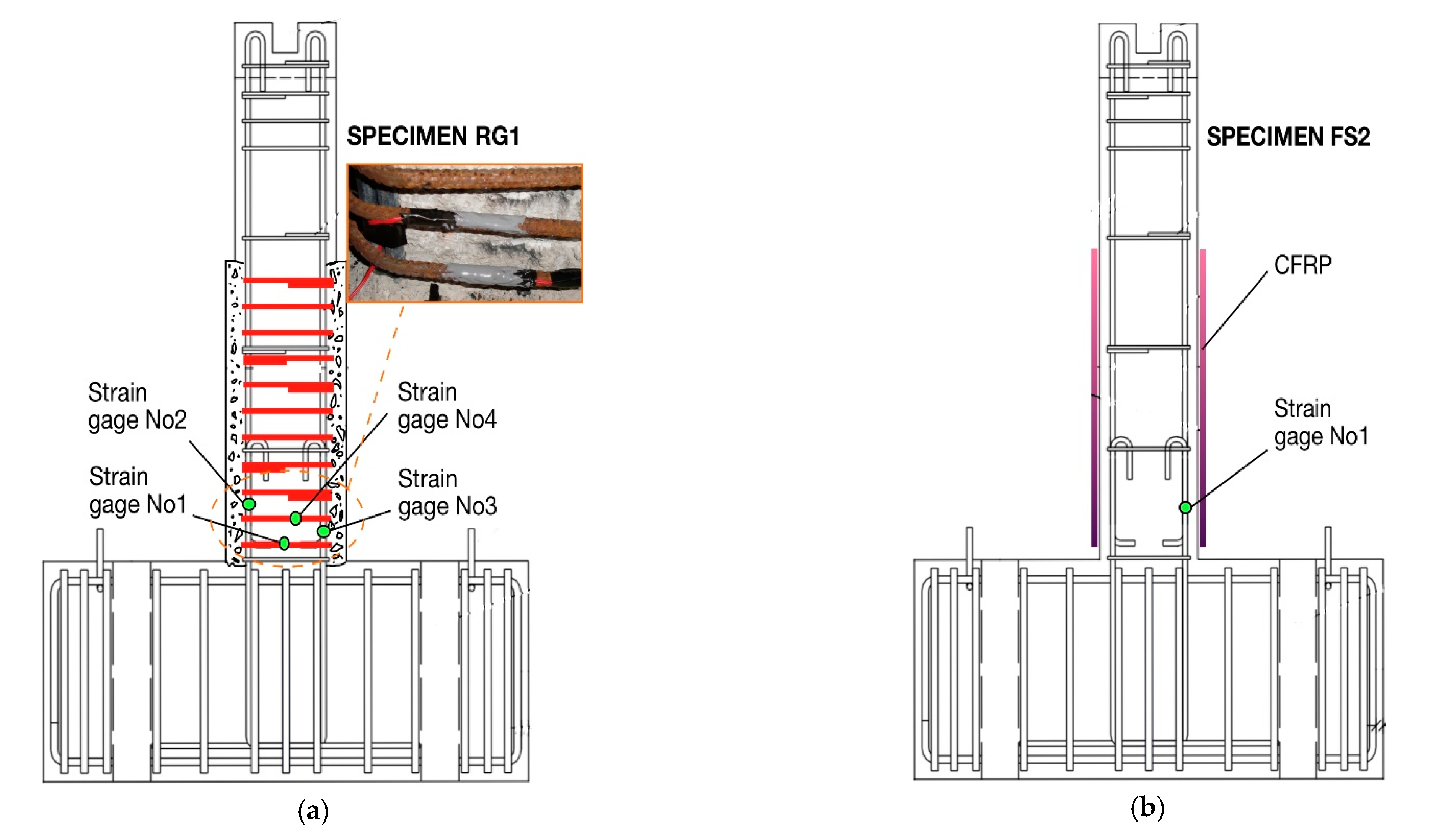
In the case of specimens RG1 and RG2, the necessary external confinement for ensuring yielding of the columns’ inadequately lap-spliced reinforcement was provided by a thin RC jacket of high strength. Using a jack hammer, the concrete cover along the column critical height was chipped-away prior to the construction of the jacket. Subsequently, B500C steel bars of 8 mm diameter were placed in touch with the initial column, while they were formed as closed ties spaced at equal distances of 50 mm (see Figure 2a,b). Eventually, eleven ties were used to confine the critical column height (600 mm). Moreover, electrical resistant strain gages were attached to the ties of the jacket to allow for the measuring of the of steel strain value variations during cycling and ascertain if yielding of reinforcement was achieved. Then, the premixed, rheoplastic, non-shrink and non-segregating concrete of high strength was poured into the wooden formwork, which was constructed around the column of each specimen. The material characteristics of the thin RC jacket of high strength are illustrated in Table 1 and Table 2.
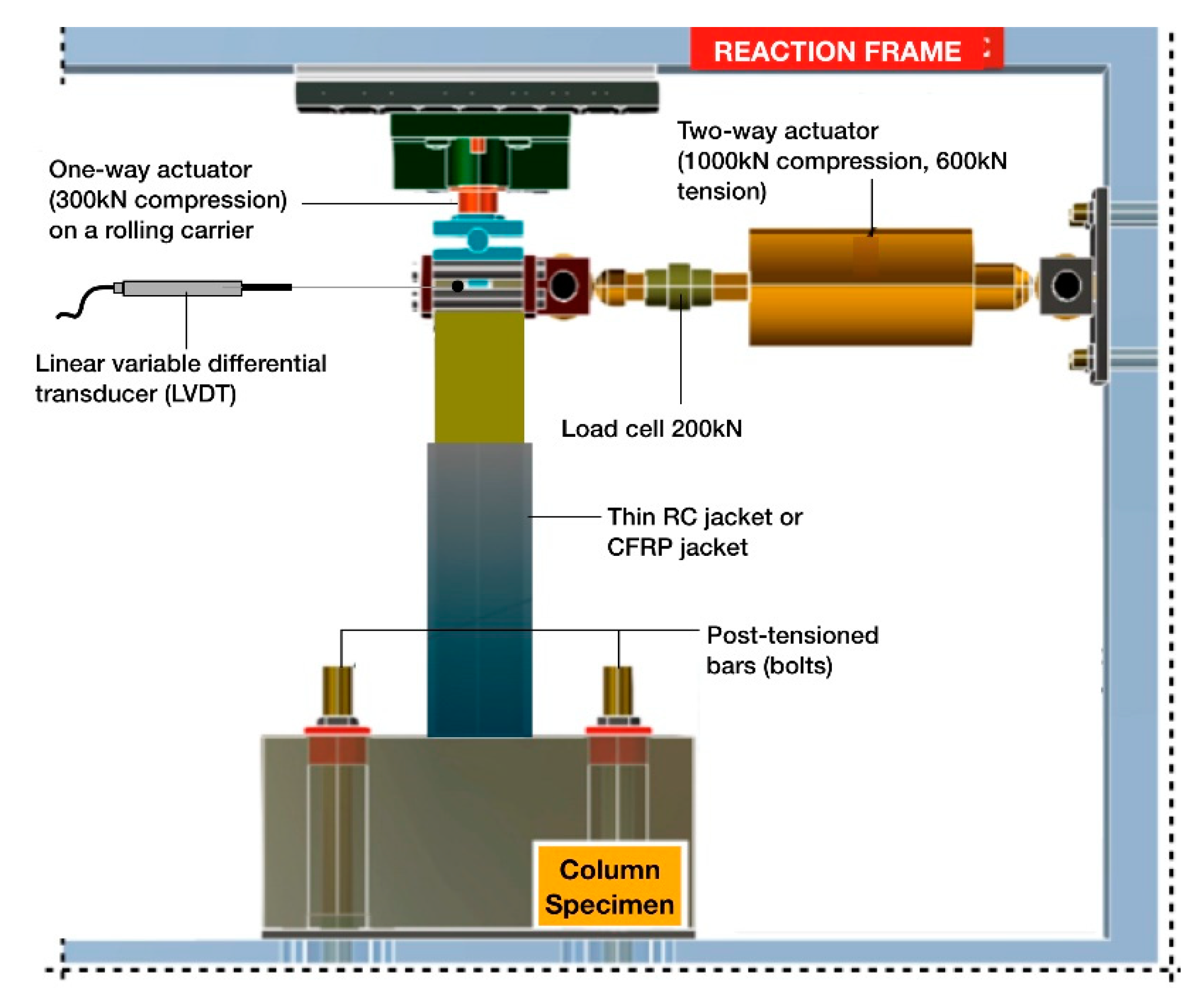
The seismic response of the enhanced columns, FS2, RG1 and RG2 was thoroughly experimentally investigated by conducting seismic tests in the test setup, which is located at the Laboratory of Reinforced Concrete and Masonry Structures of the Aristotle University of Thessaloniki (see Figure 3). The earthquake-type loading was intentionally performed with a strain rate corresponding to static conditions, which is lower than that of a dynamic earthquake event. As a result, the column specimens exhibited somewhat lower strengths with respect to the strengths they would exhibit if subjected to displacement histories similar to actual seismic events [32,33,34]. Two post-tensioned bars (bolts) were used to fix the strong foundation block of each column specimen to the reaction frame. Thus, both the horizontal and the vertical displacement, as well as the rotation of the foundation block, were effectively precluded (see Figure 3). Subsequently, the reversed lateral loading was applied by slowly displacing the column free end of the specimen. This was achieved by using a two-way actuator perpendicular to the column axis. The reversed inelastic deformations causes cumulative damage, while the seismic performance of the column is mainly demonstrated by the envelope curves. Thus, a constantly ascending lateral displacement history with one cycle per amplitude of displacement was adopted (see Figure 4) without considerable influence in the seismic performance of the specimens [35,36,37]. Meanwhile, a compressive axial force was applied to the column by a one-way actuator, which was laying on a rolling carrier (see Figure 3). The axial force was controlled to remain constant during cycling, equal to 150 kN.
The lateral displacement values of the column’s load point were measured using a calibrated linear variable differential transducer (LVDT) throughout testing. Moreover, the resisted shear force values were constantly recorded to a data acquisition system by using a load cell (see Figure 3). Thereupon, the hysteresis loops of the specimens were drawn. The latter fully reflect the performance of the columns, while allowing for the interpretation of their seismic behavior. Furthermore, electrical resistant strain gages were installed on the inadequately lap-spliced bars of the columns, as well as on the ties of the thin, high-strength RC jackets. This instrumentation was used for measuring the variation in the steel strain values and to ascertain if yielding or/and strain-hardening of reinforcement occurs or not. This is crucial for evaluating the effectiveness of the retrofitting scheme in improving the seismic performance of the columns. For instance, the development of post-yield steel strain values presupposes that the bonding between the concrete and the steel bars is adequate to prevent early slipping of reinforcement. This, in turn, demonstrates the effectiveness of the strengthening scheme in improving the bond stress by means of the applied external confinement. Contrarily, the descending strain values during the consecutive cycles of lateral displacement are related to premature bond-slip failure and, hence, to the slipping of the lap-spliced bars.
3. Results
The cyclic response of the enhanced column specimens, FS2, RG1 and RG2, was thoroughly investigated, both experimentally and analytically, to assess the efficiency of the retrofit schemes examined herein, which included the CFRP-wrapping or the thin RC jacketing of the column critical region. Thus, the perceived lateral strength, peak-to-peak stiffness and energy dissipation capacity are subsequently evaluated based on the data acquired during the seismic tests (see Figure 5, Figure 6 and Figure 7).
3.1. Interpretation of the Seismic Performance of the Strengthened Specimens
Due to numerous and significant structural deficiencies (for instance, the use of plain steel reinforcement and concrete of low compressive strength, the inadequacy of confinement and the short length of the lap splices which are located in the potential plastic hinge region), the columns found in RC structures of the 1950s–1970s possess poor deformability and low ductility, while also exhibiting a rapidly degrading hysteresis performance, related to catastrophic partial or general collapse. Thus, the efficiency and reliability of the applied retrofit scheme is primarily and inseparably related to the satisfactory transformation of the brittle failure mode to a more ductile one, by securing the full exploitation of the material properties and, hence, the development of the column’s nominal flexural moment capacity.
For this purpose, it was considered of particular interest to evaluate the effectiveness of the two examined strengthening schemes (which include either the CFRP-wrapping of the columns or the use of thin high-strength RC jackets) by comparing the hysteresis behavior of the strengthened columns with the seismic response of two corresponding original column specimens with inadequate lap splices, O1 and O2, as well as with that of a control specimen with continuous reinforcement, C1, which were all tested in a previous work [3]; see Figure 5d, Figure 6 and Figure 7. The original columns, O1 and O2, with lap splices of 200 and 240 mm length, respectively, demonstrated poor seismic performance dominated by premature excessive slipping of the inadequately lap-spliced bars, while they eventually collapsed due to the loss of axial load-carrying capacity. Contrariwise, the control specimen, C1, performed in a ductile manner when subjected to the same history of reversed inelastic lateral displacements.
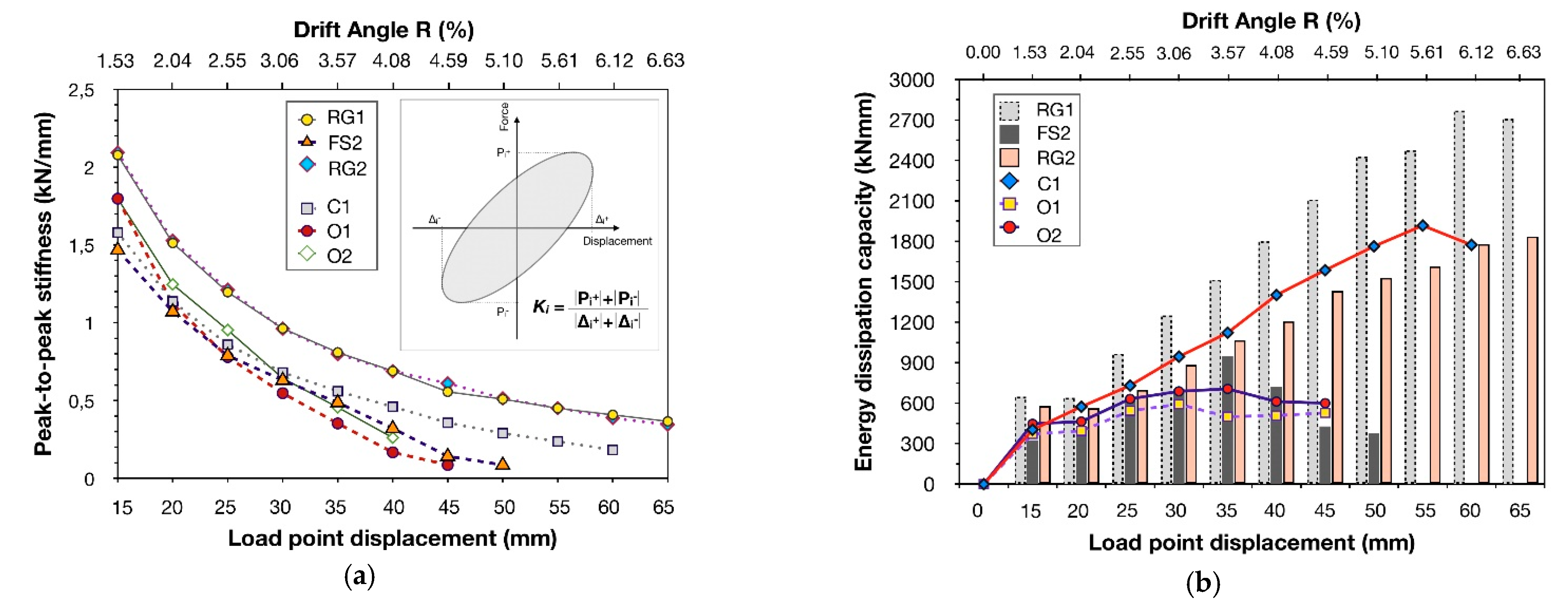
The column specimen RG1 was pre-earthquake strengthened with a thin RC jacket of high-strength and it was subsequently subjected to eleven cycles of lateral displacement increments. The amount of confinement provided by the ties of the jacket was calculated using Equation (1), while the width of the jacket equaled 15 mm. The seismic behavior of RG1 is clearly reflected in the hysteresis loops shown in Figure 5a. The lateral bearing strength and peak-to-peak stiffness showed a mild reduction during cycling, while the cumulative hysteresis dissipated energy progressively increased significantly (see Figure 6).
During the first cycle of the earthquake-type loading, the main flexural crack was formed at the base of the column. This crack gradually dilated with the increase in lateral displacement, resulting in increased post-yield strain of the lap-spliced steel bars. Nevertheless, no other crack was observed on the jacket surface until the end of testing (drift angle equal to R = 6.63%), as can be observed from the failure mode depicted in Figure 8a. Eventually, the specimen maintained 82.75% and 69.44% of its initial lateral bearing strength in the case of the push-half cycles and the pull half-cycles, respectively. Moreover, the confinement provided by the thin high-strength RC jacket effectively restrained the slipping of the longitudinal column reinforcement. The latter is clearly reflected in the plots of resisted shear force-versus-displacement, illustrated in Figure 5a, where it can be observed that increasing values of lateral strength are required for further displacing the column free end. For lateral drift angle values, R, higher than 4.59%, the unloading (lower) branch of the push half-cycles and the unloading (upper) branch of the pull half-cycles become almost horizontal, causing slight pinching of the hysteresis loops. This is attributed to the P–δ effect and the significant influence of the axial load.
During the first two cycles of the earthquake-type loading, the peak-to-peak stiffness of specimen RG1 deteriorated sharply due to the concrete cracking, showing a reduction of 27.19%. Thereupon, the deterioration rate was slower, while, at the end of testing, the column maintained almost 18% of its initial stiffness (see Figure 6a).
The strengthened specimen RG1 also showed a remarkable dissipating hysteresis behavior with constantly increasing values of dissipated seismic energy during the consecutive cycles of loading. In particular, the amount of dissipated seismic energy during the eleventh cycle of loading was increased by almost 318% with respect to the corresponding value during the first cycle (Figure 6b and Figure 9c).
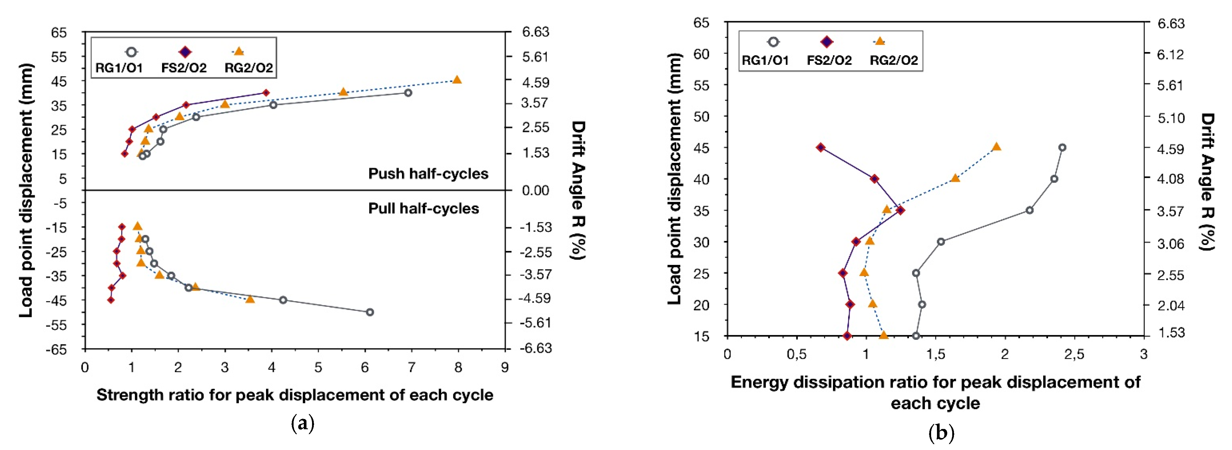
Ultimately, the strengthening scheme applied to specimen RG1 effectively prevented the premature bond-slip failure and excessive bar slipping, while also securing the desirable ductile seismic performance of the column. Furthermore, the thin high-strength RC jacket substantially increased the lateral bearing strength of the enhanced column, RG1, with respect to the strength of the corresponding original column, O1, as can be observed in the plots of strength ratio for peak displacement of each cycle-versus-load point displacement, shown in Figure 7a. For instance, for lateral displacement of 45mm the strength ratio value RG1/O1 equals 6.9 and 6.1 for the push half-cycle and the pull half-cycle, respectively. The same is also true in the case of the energy dissipation capacity of specimen RG1 with respect to that of O1. In particular, as was obtained in the plots of energy dissipation ratio for peak displacement of each cycle-versus-load point displacement (see Figure 7b), the energy dissipation ratio value RG1/O1 ranged from 1.74 for the first cycle of loading to 4.0 for the seventh cycle, when the original column, O1, literally collapsed.
It is worth noting that the hysteresis performance of the strengthened column, RG1, was also improved with respect to that of the control specimen, C1. In fact, RG1 showed significantly increased lateral strength values with respect to specimen C1 (see Figure 5d), due to the additional ties and the high-strength concrete of the thin RC jacket. An increase of almost 25% in the peak-to-peak stiffness values was also observed throughout testing (see Figure 6a). This results from the slight increase in the dimensions of the strengthened column’s cross-section, but is mainly caused by the additional confinement provided by the thin high-strength RC jacket. Moreover, during the eleven cycles of the earthquake-type loading the mean value of the energy dissipation ratio, RG1/C1, equaled to 1.36. The latter clearly demonstrates the ductile seismic response of the enhanced column RG1 and, hence, the effectiveness of the applied retrofit scheme.
The enhanced specimen RG2 was retrofitted similarly to the RG1. From the plots of resisted shear force-versus-displacement of RG2 (see Figure 5b), it can be observed that both the lateral strength and the peak-to-peak stiffness showed a mild reduction during testing, while the energy dissipation capacity of the column gradually increased significantly during the consecutive cycles of the earthquake-type loading. The main flexural crack was formed at the base of the column during the first cycle. Thereafter, this crack dilated progressively with the increase in the reversed lateral displacements of RG2, causing excessive deformation of the lap-spliced column reinforcement. For a drift angle value equal to R = 4.59% a hairline flexural crack was formed on the jacket surface at the exact location where the lap splices of the reinforcement end, namely at a distance of 240 mm from the foundation block of the specimen. Propagation of this crack occurred in the circumference of the thin high-strength RC jacket, due to the gradual increase in lateral displacement values until the end of testing (see Figure 8b). However, no significant further dilation of this crack or disintegration of the concrete was observed. Thus, the thin RC jacket satisfactorily confined the column’s critical region to prevent early bond-slip failure and excessive slipping of the bars, while the enhanced column, RG2, exhibited a ductile dissipating hysteresis behavior.
The slipping of reinforcement was effectively restricted, and it was not before the ninth push half-cycle when bar slipping showed a considerable increase. The latter is perceived in the hysteresis loops of RG2 by the less steep (almost horizontal) upper branch of the push half-cycles (see Figure 5b). Notably, this is not true for the pull half-cycles, where the continuously ascending lower branch of the hysteresis loops reveals that increasing values of lateral shear force are required to further displace the column’s free end.
Eventually, after eleven cycles of the earthquake-type loading, the strengthened column specimen, RG2, maintained 68% (push half-cycles) and 80% (pull half-cycles) of its initial lateral strength (see Figure 5b). Moreover, the peak-to-peak stiffness values of RG2 were similar to those of the enhanced column RG1, as shown in Figure 6a. The energy dissipation capacity of RG2 is illustrated in Figure 6b. As can be observed, the strengthened column showed a remarkable dissipating hysteresis behavior, with constantly increasing values of dissipated seismic energy during testing. The lower vales of the seismic energy dissipated by specimen RG2 with respect to specimen RG1 are reflected by the slightly reduced area of the hysteresis loops of RG2 compared to the loops of RG1. The latter is primarily caused by the slipping of reinforcement after the seventh push half-cycle of RG2 and, apparently, by the increased influence of the axial loading (P–δ effect). This influence is clearly demonstrated by the almost stable values of the resisted shear force, which are required for displacing the column’s free end backwards from the peak displacement of each push half-cycle (see Figure 5b). Nevertheless, the amount of dissipated seismic energy during the eleventh cycle of loading of specimen RG2 was increased by almost 220% with respect to the value of the first cycle, while also corresponding to almost 70% of the amount of energy dissipated by specimen RG1 during the eleventh cycle.
A substantial increase in the lateral-bearing strength of specimen RG2 with respect to the strength of the corresponding original column, O2, was also achieved. The latter is clearly demonstrated in the plots of strength ratio for peak displacement of each cycle-versus-load point displacement, illustrated in Figure 7a. In particular, for drift angle value R = 4.59%, the strength ratio value RG2/O2 equals 7.97 and 3.54 for the push half-cycle and the pull half-cycle, respectively. Accordingly, the peak-to-peak stiffness of the enhanced column RG2 was significantly improved with respect to that of the original specimen, O2. During the first cycle of the earthquake-type loading, the strengthened column RG2 showed an 16.5% increase in the peak-to-peak stiffness value with respect to specimen O2. Thereafter, RG2 demonstrated a slower stiffness degradation rate during the consecutive cycles of loading. For lateral displacement value of 40 mm the original column, O2, collapsed due to the loss of axial load carrying capacity, while specimen RG2 retained 32.9% of its initial stiffness. Furthermore, after eleven cycles of inelastic lateral displacement amplitudes (drift angle value, R, equal to 6.63%), specimen RG2 maintained 16.65 % of its initial stiffness value shown during the first cycle. In Figure 7b the energy dissipation capacity ratio for peak displacement of each cycle-versus-load point displacement is presented. As can be observed, a significant improvement in the dissipating hysteresis performance of RG2 with respect to O2 was indisputably achieved, due to the external confinement provided by the thin high-strength RC jacket. Indeed, the energy dissipation ratio RG2/O2 ranged from 1.29 to 2.40 during testing.
Therefore, the strengthened column, RG2, exhibited a ductile overall seismic response, which was almost similar to the behavior of the control specimen, C1, with the continuous longitudinal reinforcing bars (see Figure 5d and Figure 6b). In particular, RG2 showed significantly higher values of lateral bearing strength than the specimen C1, while also achieving an increase of almost 25% in the peak-to-peak stiffness values. As with specimen RG1, this resulted from the slight increase in the dimensions of the strengthened column’s cross-section, but is mainly caused by the additional confinement provided by the thin high-strength RC jacket. Furthermore, the mean value of the energy dissipation ratio, RG2/C1, during testing, equaled 0.98. Consequently, the strengthening interventions implemented on specimen RG2 effectively secured the satisfactory ductile seismic performance of the enhanced column and, thus, were proved to constitute a reliable and efficient strengthening scheme for improving the seismic behavior of columns found in existing pre-1960s–1970s RC structures.
Specimen FS2 was strengthened pre-earthquake by wrapping two layers of CFRP textile around the critical column region. The number of the required layers was determined using Equation (1). The column eventually exhibited brittle failure due to excessive slipping of the lap-spliced bars. In particular, during the first cycle of the earthquake-type loading, the main flexural crack was formed at the column base. The damage gradually evolved with the increase in lateral displacement values during the subsequent cycles, while progressive slipping of the lap-spliced reinforcement also occurred. As a result, the cracking at the column base sequentially dilated, and disconnection of the column from the strong foundation block of the specimen eventuated for drift angle values, R, was greater than 4.08 % (see Figure 8c). At the end of testing of FS2 (after eight cycles of reversed inelastic lateral displacements), the pullout of the column’s longitudinal reinforcing bars was apparent. The excessive slipping of the bars was also ascertained from the data acquired from strain gages, which were attached to the bars, showing almost stable steel strain values during the consecutive loading cycles (see Figure 11e) [23]. In Figure 8c, the failure mode of specimen FS2 is depicted, characterized by excessive residual deformation and rotation of the column. From the plots of energy dissipation capacity-versus-load point displacement (see Figure 6b), it can be observed that the strengthened column, FS2, performed similarly to specimens C1 and RG2 during the first five cycles of the reversed inelastic lateral displacements (drift angle, R, equal to 3.57%), while subsequently showing a degrading hysteresis behavior similar to that of the corresponding original column specimen, O2. The latter is also clearly demonstrated on the hysteresis loops of FS2 (see Figure 5c). For instance, rapid deterioration of lateral bearing strength and peak-to-peak stiffness, intensive pinching of the hysteresis loops around the axes, horizontal branches showing excessive bar slipping and poor energy dissipation capacity dominated the hysteresis behavior of the column after the sixth push half-cycle and the fifth pull half-cycle of the seismic loading. The peak-to-peak stiffness of specimen FS2 deteriorated more sharply during the first three cycles, while it subsequently deteriorated with a slower rate. For a lateral drift angle, R, equal to 5.10%, the peak-to-peak stiffness of FS2 equaled only 1% of its initial value during the first cycle of loading (see Figure 6a). The hysteretic energy dissipation capacity of specimen FS2 was similar to the capacities of C1 and RG2 for up to a drift angle value, R, equal to 3.57%, while afterwards it was rapidly reduced due to the excessive slipping of reinforcement (see Figure 6b). Nevertheless, the confinement provided by wrapping the two layers of the CFRP textile around the column of specimen FS2 improved the failure mode of the specimen with respect to that of the corresponding original specimen, O2 [3]. In particular, the evolution of damage was delayed, since excessive disintegration of the core concrete and loss of the concrete cover were effectively restricted. The strengthened column FS2 initially showed a dissipating hysteresis behavior until the fifth cycle of the seismic loading. Thereupon, excessive slipping of the lap-spliced reinforcement dominated the cyclic response of the specimen, causing a degrading overall hysteresis response.
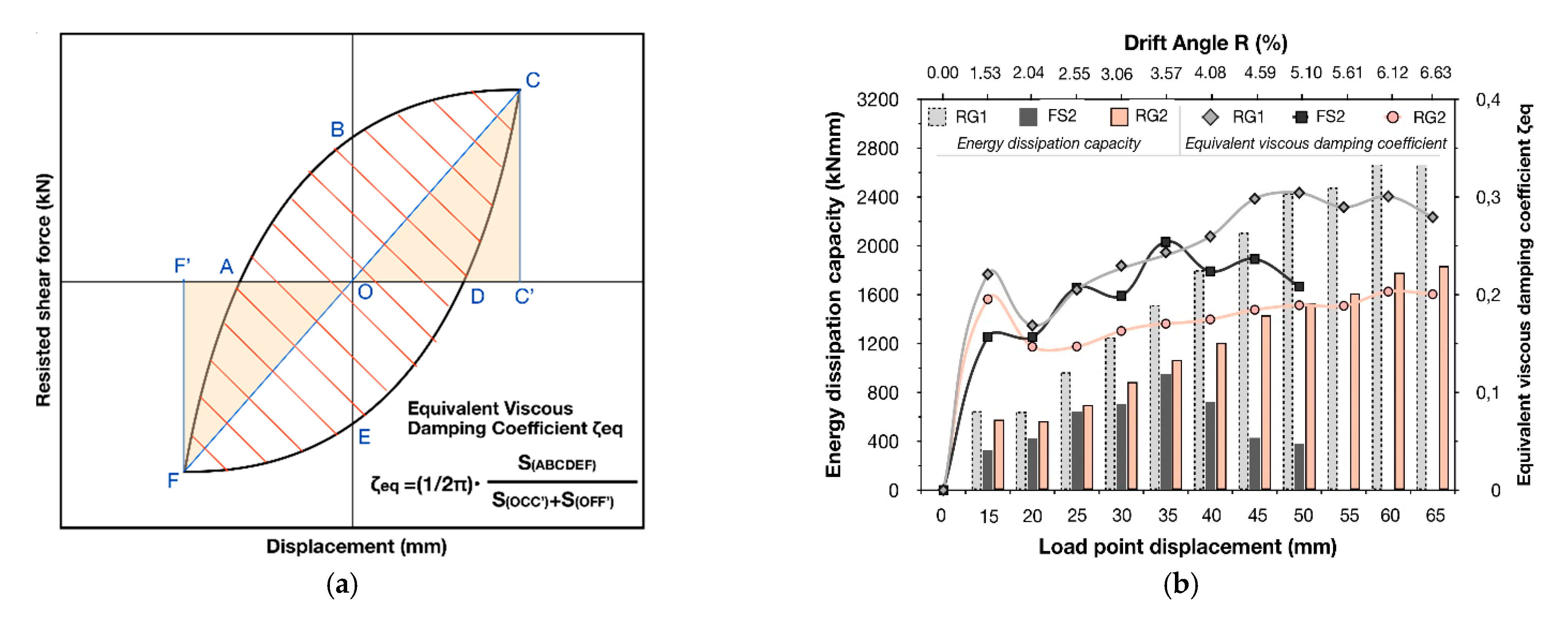
According to the capacity design approach, RC structures should be able to withstand increased values of inelastic cyclic deformations during strong seismic excitations, to allow for the dissipation of a significant amount of kinetic energy through damping. Therefore, the structures should possess adequate displacement ductility to develop acceptable damage in the plastic hinges, while preserving the structural integrity and preventing partial or general collapse. Thus, the equivalent viscous damping is highly related to the deformability, while consisting of both the elastic and the hysteretic damping. The latter is crucial for the seismic response of RC structures and depends on the post-yielding characteristics of the structural members. Furthermore, the desirable ductile seismic performance requires an adequate energy dissipation capacity of the members, which, in turn, results in higher equivalent viscous damping ratios. Contrarily, the RC structural members with low energy dissipation capacity exhibit poor hysteresis behavior, while being susceptible to collapse due to the cumulative dissipated energy under small deformations.
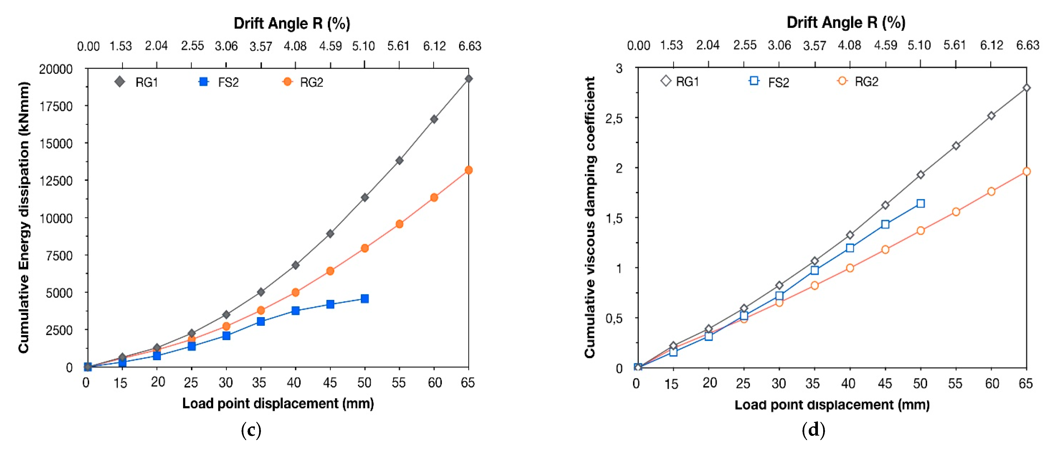
In order to evaluate the capacity of RC structural members for dissipating seismic energy, Equation (2) was used [38]. According to this equation, the equivalent viscous damping coefficient, ζeq, is expressed as the ratio of the dissipated energy within a given cycle of the earthquake-type loading (represented by the area SABCDEFA) to the elastic strain energy associated with the maximum force and displacement of the given hysteresis loop (represented by the areas SOCC′ and SOFF′) (see Figure 9a). The energy dissipation capacity and the equivalent viscous damping coefficient, ζeq, per cycle of loading are depicted in Figure 6b and Figure 9b, while in Figure 9c,d, the cumulative dissipated energy and the cumulative equivalent viscous damping coefficient of specimens FS2, RG1 and RG2 for different drift ratio values are illustrated.
The enhanced columns RG1 and RG2 showed similar lateral resistance throughout testing and, therefore, similar elastic strain energy values (see Figure 5a,b and Figure 9a). As a result, the cumulative equivalent viscous damping coefficient values of specimen RG1 were higher than the corresponding ones of column RG2, because the latter showed a lower energy dissipation capacity with respect to RG1 (see Figure 6b and Figure 9b–d). Additionally, it is worth noting that specimen FS2, which was strengthened by CFRP-wrapping, dissipated an almost similar amount of seismic energy with specimen RG2 during the first five loading cycles (up to a drift angle ratio equal to 3.57%) (see Figure 6b). However, the shear resistance of FS2 was a portion of that of RG2 (see Figure 5b,c). As a result, the elastic strain energy values of FS2 were significantly lower with respect to the ones of RG2. Consequently, the values of cumulative equivalent viscous damping coefficient of specimen FS2 appear to be slightly increased when compared to the corresponding ones of RG2 (see Figure 9b,d).
3.2. Monitoring of the Steel Bar Micro-Strain
The seismic performance of existing RC structures, built prior to the 1960s–1970s, is mainly dominated by brittle failures of the columns and beam-to-column joints, which are related to loss of structural integrity and catastrophic partial or general collapse. Therefore, the applied retrofitting schemes should effectively prevent the occurrence of brittle failure modes, such as shear failure and/or premature excessive slipping of the lap-spliced reinforcing bars, while also securing, at least, the yielding of the columns’ longitudinal reinforcement and the development of the nominal flexural moment capacity. Accordingly, a thorough analysis of the reinforcement’s strain value variations during the reversed increments of inelastic lateral displacement would provide valuable information regarding the effectiveness of the applied retrofit scheme. Similar work can be found in the literature [39,40], where the transverse reinforcement and fiber hoop strains were monitored experimentally.
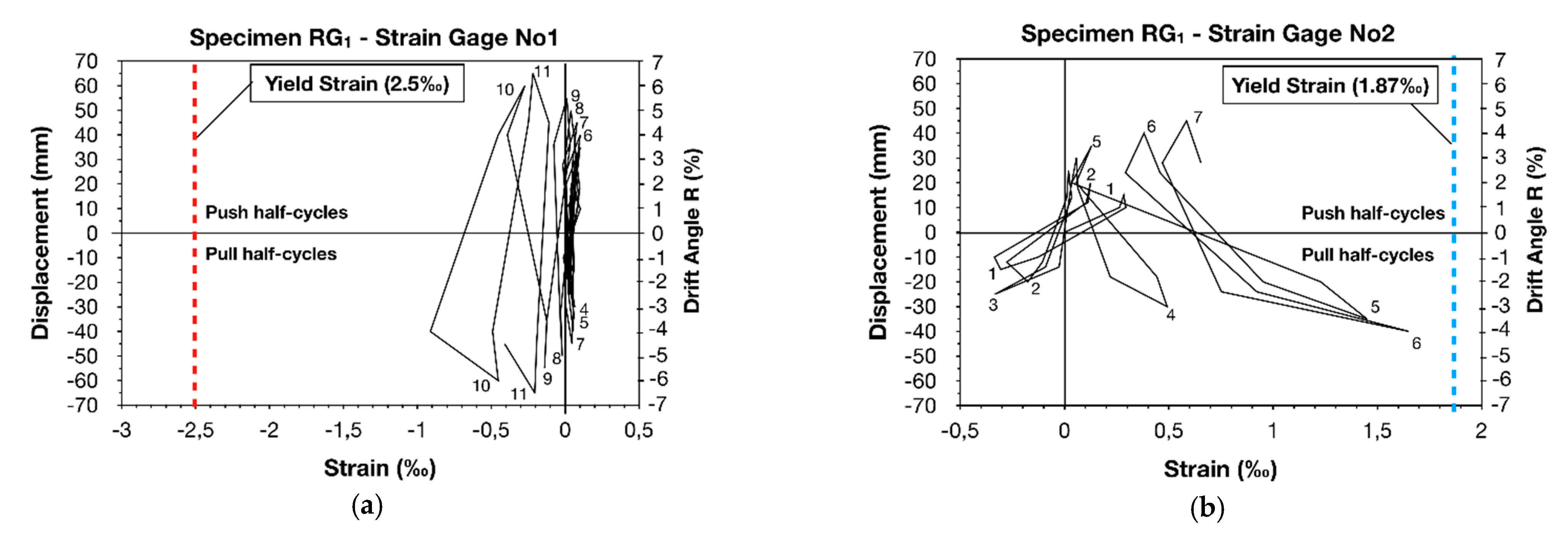
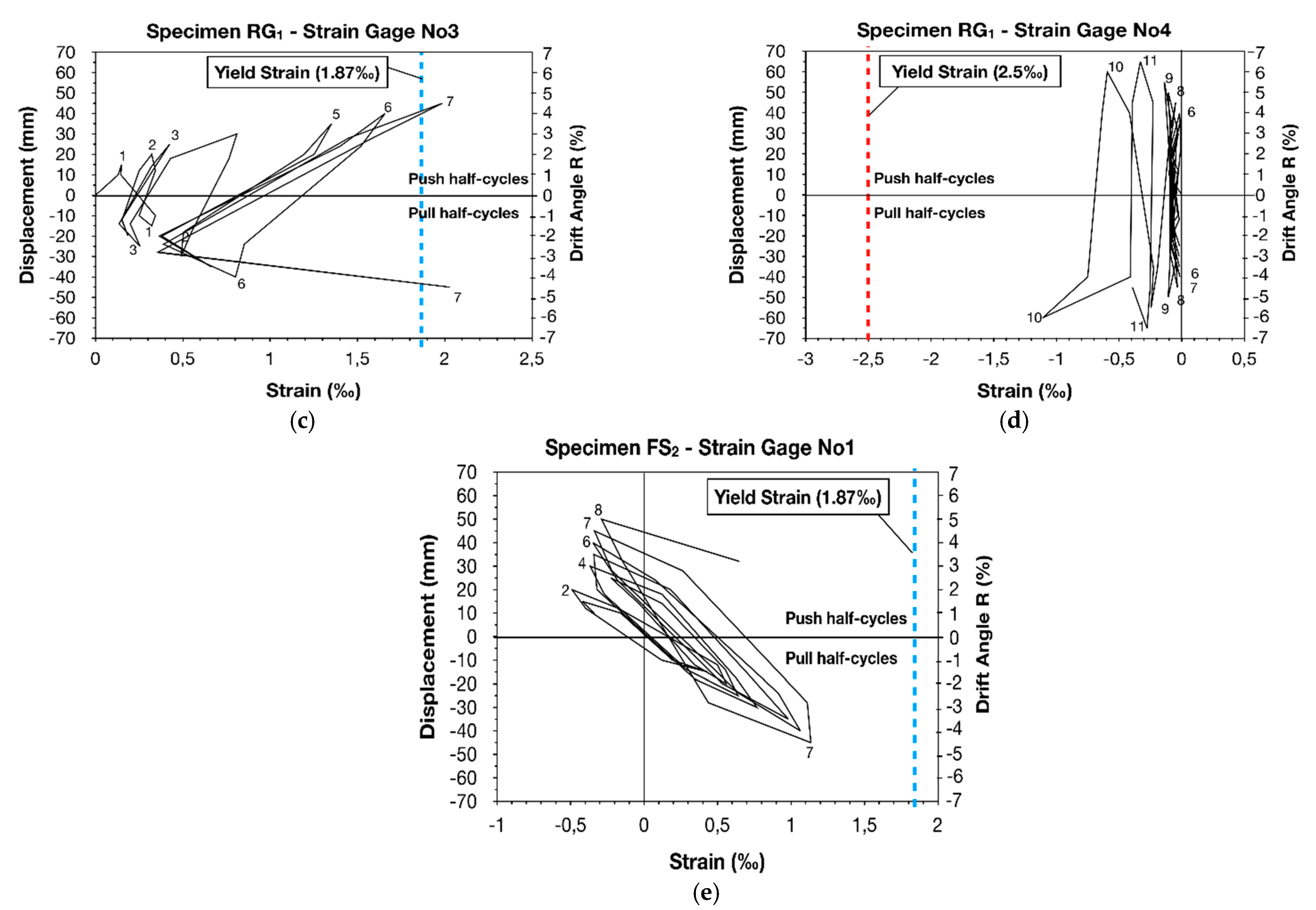
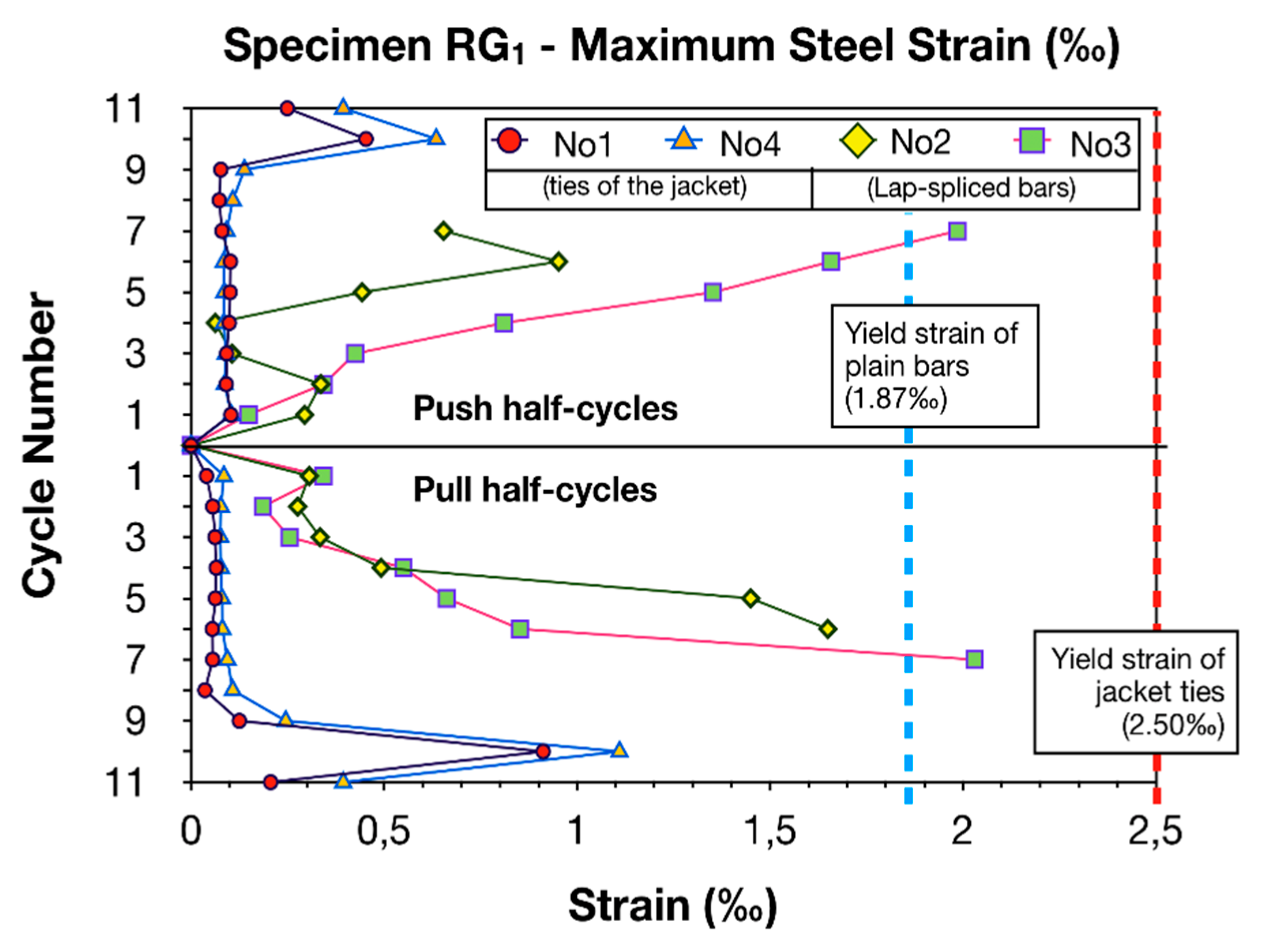
For this reason, electrical resistant strain gages were attached to the lap-spliced bars of the column specimens, as well as to the ties of the thin high-strength RC jackets of RG1 and RG2, to allow the monitoring of steel stain variations during the earthquake-type loading and ascertain if yielding of the bars was achieved. The exact location of the strain gages is illustrated in Figure 10, while in Figure 11 and Figure 12 the plots of the load point displacement-versus-strain of reinforcement and the plots of maximum steel strain per cycle of loading are illustrated, respectively. Based on the strain analysis (see Figure 10, Figure 11 and Figure 12), it was concluded that the continuously increasing strain values of the lap-spliced reinforcement of strengthened specimen RG1 resulted from both the confinement offered by the additional ties and from the high-strength concrete of the jacket, which replaced the concrete of low compression strength in the lap splice region. This dual contribution of the jacket substantially increased the bond stress between the bars and the concrete along the inadequate lap splice length and allowed for a satisfactory load transfer between the lap-spliced reinforcement. Therefore, yielding of reinforcement ( 1.87‰) was eventually achieved (see Figure 11b,c and Figure 12). Moreover, it was clearly demonstrated that only minor steel strain (significantly lower than the yielding strain 2.50‰) was developed in the ties of the RC jacket (see Figure 11a,d and Figure 12). The latter was further substantiated by the failure mode of specimen RG1, which did not include any damage to the thin RC jacket (no increase in volume of the core concrete or loss of the concrete cover were observed). Consequently, it was evinced that the strengthened specimen RG1 exhibited a ductile dissipating hysteresis response due to the satisfactory performance of the thin high-strength RC jacket. The same is also true for specimen RG2. The CFRP-strengthened column, FS2, showed increasing strain values of the lap-spliced reinforcement during the consecutive cycles of loading. This continuous increase in steel strain values up to the fifth cycle of loading indicates an absence of bar slipping for a drift angle ratio of up to 3.57% [36]. However, the strain values remained lower than steel yielding strain 1.87‰ (see Figure 11e). Thus, from the measurements of the strain gages, it was demonstrated that the confinement provided by the CFRP jacket was insufficient to allow yielding of the lap-spliced bars. The latter is attributed to the unexpected failure of the jacket, which, in turn, caused loss of the confinement provided to the lap splice region, while triggering brittle bond-slip failure and slipping of the bars.
3.3. Theoretical Conciderations
Kalogeropoulos and Tsonos [3,7] recently proposed a modified version of the analytical model proposed by Tsonos [41,42,43], to predict the seismic performance of RC columns of both existing pre-1960–1970s and modern RC structures. The latter can be achieved by controlling the adequacy of length of the lap-spliced reinforcement. Furthermore, the formulation is used to precisely determine the necessary confinement which should be provided by the strengthening material during the retrofitting of existing RC structures, in order to prevent early failure of the lap splices. Thus, the implementation of the proposed methodology ensures the satisfactory design of the retrofit schemes, which allows for the yielding of the inadequately lap-spliced bars and the development of the column’s nominal flexural moment capacity.
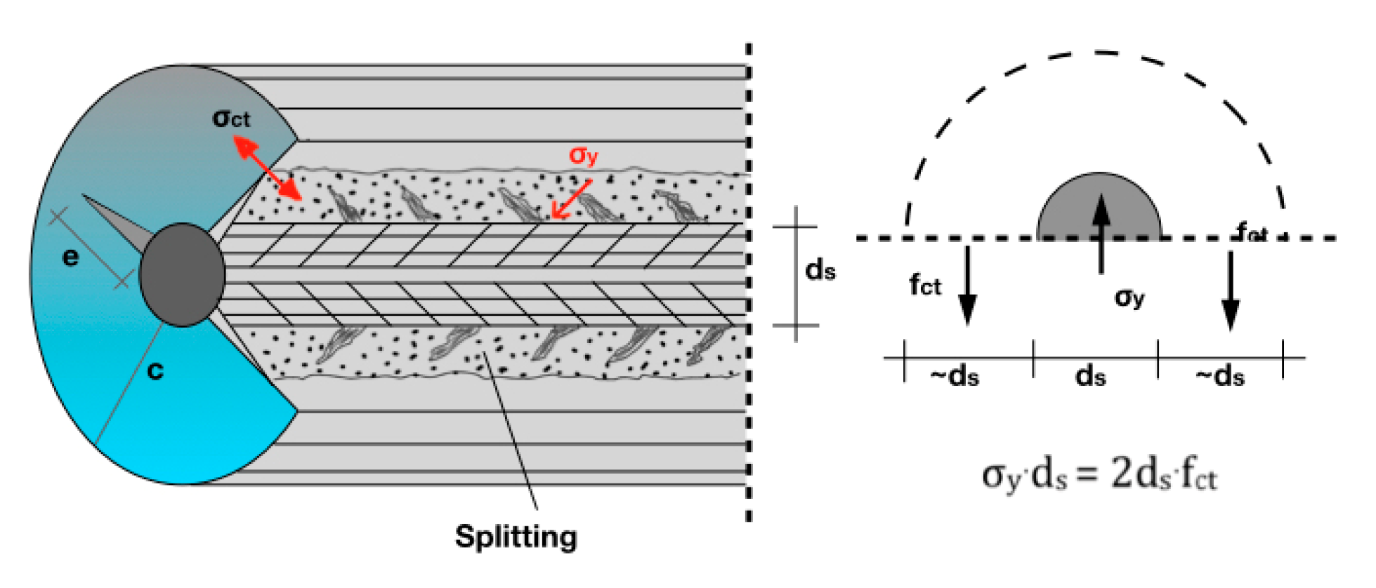
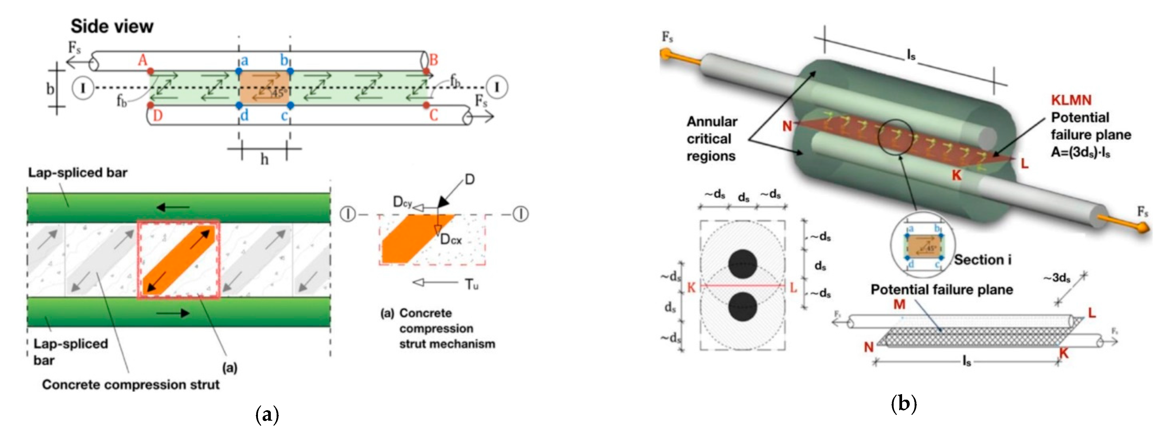
In Figure 13 and Figure 14, the details of the lap-spliced column reinforcing bars are depicted. As can be observed, the shear forces, acting on a 45 degree angle [44], are resisted by the concrete compression struts that act between diagonally opposite corners of each rectangular section “abcd”. The diagonal compression strut mechanism depends on the concrete strength and, therefore, failure of the concrete causes a limitation of the strength of the lap splice, due to the gradual crushing along the cross-diagonal cracks, and especially along the potential failure plane, KLMN (see Figure 14b). Meanwhile, slipping of the bars occurs.
According to the proposed methodology, which was presented in detail in previous works [3,7], the ultimate strength of the lap splice is given by Equation (3), where the values of x and ψ are given by Equations (4) and (5), respectively and the aspect ratio value α = h/b is always equal to 1.0. The increased value of the concrete compressive strength,, due to the confinement provided by the jacket, is calculated using Equations (6) and (7) [45].
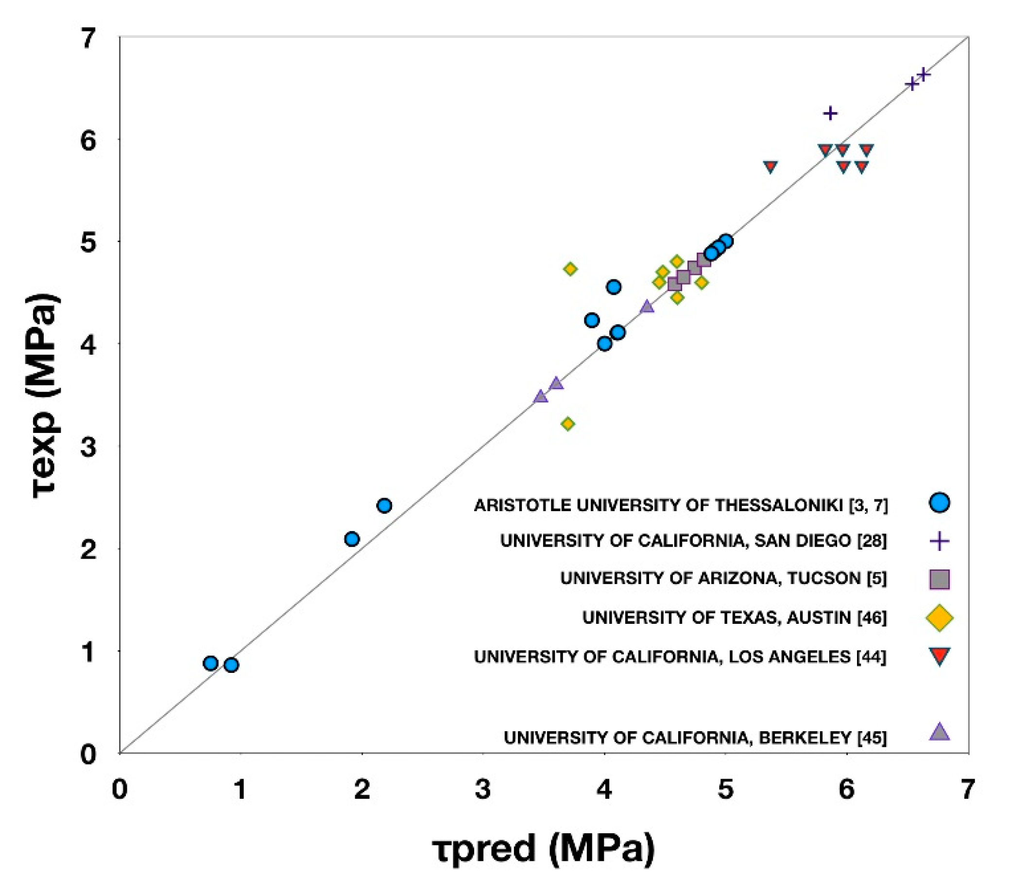
The validity of the proposed analytical model was checked using experimental data from 13 column specimens tested in the Laboratory of Reinforced Concrete Structures and Masonry Buildings of the Aristotle University of Thessaloniki [3,7], as well as data from 23 similar experiments found in the literature [5,30,46,47,48] (see Figure 15). In Table 4, the shear capacities and the predicted actual values of the lap splice shear stress are shown. In particular, the value of actual shear stress in the potential failure plane between the lap-spliced bars when yielding of the bars occurs is . Thus, is calculated when the tension force acting in the bar,, equals the bond force developed between the bar and the concrete along the lap splice, , where is the area of the potential failure plane. The coeficient is calculated from Equations (3)–(7), and the ultimate shear stress is subsequently given by the expression . The value of is calculated from the expression , where is the stress value calculated according to the Hook’s law () using the maximum measured steel strain value,. The latter is measured experimentally by strain gages attached to the steel bar (). If the measured maximum strain, , exceeds the yielding strain,, then is used to calculate the developed stress ( since the Hook’ law is not applied in the post-yielding range. According to the analytical formulation when the calculated shear stress is lower than the ultimate strength, , then the predicted actual value of the lap splice shear stress will be near , because the lap splice permits the yielding of reinforcement . Contrarily, when lap, splice failure occurs prior to the yielding of reinforcement and . In the case of specimens RG1 and RG2, it was demonstrated that the implementation of the analytical model ensured the satisfactory design of the thin RC jackets, which provided adequate confinement to the lap splice region and allowed for the yielding of the inadequately lap-spliced bars.
4. Conclusions
In the present study, the effectiveness of two strengthening schemes in improving the overall hysteresis performance of RC columns with poor seismic details was experimentally and analytically investigated. Three column specimens of 1:1.5 scale were constructed, designed for gravity loads only. The main structural deficiencies of the columns included the use of concrete with low compressive strength, plain steel reinforcement, widely spaced ties and inadequate length of the lap splices of reinforcement. Subsequently, these specimens were enhanced by either wrapping layers of CFRP textile along the critical column height (specimen FS2) or by using high-strength concrete to confine the critical region with a thin RC jacket (specimens RG1 and RG2). The strengthened columns were then subjected to a large number of incremental amplitudes of lateral displacement under constant axial loading, to simulate the equivalent effect of strong earthquake motions. The examined variables were the strengthening material, the length of the lap splices and the amount of confinement provided by the jackets. Based on both the experimental data acquired during the seismic tests and the implementation of the proposed analytical formulation, a comprehensive analysis of the hysteresis response of the specimens was attempted. Moreover, the seismic behavior of the strengthened columns was further evaluated with respect to the cyclic performance of two corresponding original specimens, O1 and O2, and the response of a control one, C1, with continuous reinforcement, which were tested in a previous work [3].
It was clearly demonstrated that the thin RC jackets of high strength provided adequate confinement to the critical region of specimens RG1 and RG2, where the lap splices of reinforcement are located, and hence, satisfactorily improved the load transfer mechanism between the lap-spliced bars. Meanwhile, premature lap splice failure and excessive bar slipping were effectively precluded. Consequently, the strengthening interventions applied to specimens RG1 and RG2 allowed for the development of the columns’ nominal flexural moment capacities, while securing a ductile dissipating hysteresis behavior. Thus, RG1 and RG2 showed an indisputably superior hysteresis behavior with respect to the seismic response of the original columns, O1 and O2, which was mainly dominated by bond-slip failure and excessive slipping of the lap-spliced reinforcement which, eventually, resulted in the collapse of the specimens due to the loss of axial load-carrying capacity. It is also worth noting that the application of the aforementioned strengthening scheme is relatively easy and requires limited labor work with respect to the application of conventional RC jacketing. Furthermore, due to the limited dimensions of the thin high-strength RC jacket, only minimal impact is caused in the exploitation of the available floor space. Ultimately, the use of a thin high-strength RC jacket was proved to be an efficient, cost-effective and competitive strengthening scheme which can be easily applied, while able to secure a satisfactory seismic performance of the strengthened non-ductile RC columns when implementing the proposed analytical formulation to define the necessary confinement.
The strengthened specimen FS2 showed almost similar values of dissipated hysteresis energy with specimen RG2 for a drift angle ratio up to 3.57 %, which were also increased with respect to the corresponding values of the original column, O2. Moreover, the confinement provided by the CFRP jacket improved the failure mode of FS2 with respect to that of specimen O2, since excessive disintegration of the core concrete and loss of the concrete cover were not observed in the case of FS2. However, due to the unexpected premature failure of the CFRP jacket, column FS2 exhibited a rapidly degrading hysteresis behavior, dominated by the excessive slipping of the lap-spliced bars. This indicates the severe consequences of the brittle failure of the CFRP jacket in the seismic response of the strengthened column. In particular, the cracking of the CFRP jacket triggered immediate loss of the provided confining stress, which resulted in the slipping of the inadequately lap-spliced reinforcement. Contrarily, specimen RG2 showed a continuous increase in the energy dissipation capacity during the consecutive cycles of the earthquake-type loading until the end of testing, despite the cracking formed in the circumference of the thin high-strength RC jacket. This is attributed to the beneficial influence of the jacket’s ties in the confinement of the existing column. Eventually, it was concluded that wrapping layers of CFRP textile around the column’s critical region may also be a cost-effective and easy-to-apply strengthening scheme with negligible influence on the dimensions of the column [7], which can satisfactorily improve the seismic response of the column only if premature failure of the CFRP jacket is successfully precluded to allow for the yielding of the lap-spliced bars.
Author Contributions
Conceptualization, A.-D.T. and G.K.; methodology, A.-D.T. and G.K.; software, G.K.; validation, A.-D.T. and G.K.; formal analysis, G.K.; investigation, G.K.; resources, G.K.; data curation, G.K.; writing—original draft preparation, G.K.; writing—review and editing, A.-D.T. and G.K.; visualization, G.K.; supervision, A.-D.T.; All authors have read and agreed to the published version of the manuscript.
Funding
This research received no external funding.
Institutional Review Board Statement
Not applicable.
Informed Consent Statement
Not applicable.
Data Availability Statement
Not applicable.
Acknowledgments
The authors gratefully acknowledge the kind donation of the steel reinforcement by Sidenor S.A. industry, while also acknowledge ISOMAT S.A. industry for the free construction of the CFRP jacket. Moreover, the authors would like to express their thanks to the Alexia Chalkia, Georgia Kyrkousi and Sofia Panagiotou for their contribution in the stage of the measurement acquirement during the seismic tests.
Conflicts of Interest
The authors declare no conflict of interest.
References
- Tsonos, A.-D. Design of Reinforced Concrete Structures according to Eurocodes; Sofia: Thessaloniki, Greece, 2017; p. 654. (In Greek) [Google Scholar]
- Paulay, T.; Priestley, M.J.N. Seismic Design of Reinforced Concrete and Masonry Buildings; John Wiley and Sons: New York, NY, USA, 1992. [Google Scholar]
- Kalogeropoulos, G.; Tsonos, A.D. Improvement of the cyclic response of RC columns with inadequate lap splices—Experimental and analytical investigation. Earthq. Struct. 2019, 16, 279–293. [Google Scholar] [CrossRef]
- Yeh, Y.; Mo, Y. Shear retrofit of hollow bridge piers with carbon fiber-reinforced polymer sheets. J. Compos. Constr. 2005, 9, 327–336. [Google Scholar] [CrossRef]
- Saadatmanesh, H.; Ehsani, M.R.; Jin, L. Repair of earthquake-damaged RC columns with FRP wraps. ACI Struct. J. 1997, 94, 206–214. [Google Scholar]
- Pavese, A.; Bolognini, D.; Peloso, S. FRP seismic retrofit of RC square hollow section bridge piers. J. Earthq. Eng. 2004, 8, 225–250. [Google Scholar] [CrossRef]
- Kalogeropoulos, G.; Tsonos, A.D. Cyclic performance of RC columns with inadequate lap splices strengthened with CFRP jackets. Fibers 2020, 8, 39. [Google Scholar] [CrossRef]
- Chalioris, C.E.; Kosmidou, P.-M.K.; Papadopoulos, N.A. Investigation of a new strengthening technique for RC deep beams using carbon FRP ropes as transverse reinforcements. Fibers 2018, 6, 52. [Google Scholar] [CrossRef] [Green Version]
- Chalioris, C.E. Analytical model for the torsional behaviour of reinforced concrete beams retrofitted with FRP materials. Eng. Struct. 2007, 29, 3263–3276. [Google Scholar] [CrossRef]
- Gopinath, S.; Murthy, A.R.; Patrawala, H. Near surface mounted strengthening of RC beams using basalt fiber reinforced polymer bars. Constr. Build. Mater. 2016, 111, 1–8. [Google Scholar] [CrossRef]
- Jabr, A.; El-Ragaby, A.; Ghrib, F. Effect of the fiber type and axial stiffness of FRCM on the flexural strengthening of RC beams. Fibers 2017, 5, 2. [Google Scholar] [CrossRef]
- Tsonos, A.G. Effectiveness of CFRP jackets in post-earthquake and pre-earthquake retrofitting of beam-column subassemblages. Struct. Eng. Mech. 2007, 27, 393–408. [Google Scholar] [CrossRef]
- Tsonos, A.-D. Effectiveness of CFRP-jackets and RC-jackets in post-earthquake and pre-earthquake retrofitting of beam-column subassemblages. Eng. Struct. 2008, 30, 777–793. [Google Scholar] [CrossRef]
- Tsonos, A.G. Ultra-high-performance fiber reinforced concrete: An innovative solution for strengthening old R/C structures and for improving the FRP strengthening method. WIT Trans. Eng. Sci. 2009, 64, 273–284. [Google Scholar]
- Karayannis, C.; Golias, E. Full scale tests of RC joints with minor to moderate seismic damage repaired using C-FRP sheets. Earthq. Struct. 2018, 15, 617–627. [Google Scholar] [CrossRef]
- Karayannis, C.G.; Sirkelis, G.M. Strengthening and rehabilitation of rc beam-column joints using carbon-FRP jacketing and epoxy resin injection. Earthq. Eng. Struct. Dyn. 2008, 37, 769–790. [Google Scholar] [CrossRef]
- Pampanin, S.; Bolognini, D.; Pavese, A. Performance-Based seismic retrofit strategy for existing reinforced concrete frame systems using fiber-reinforced polymer composites. J. Compos. Constr. 2007, 11, 211–226. [Google Scholar] [CrossRef]
- Napoli, A.; Matta, F.; Martinelli, E.; Nanni, A.; Realfonzo, R. Modelling and verification of response of RC slabs strengthened in flexure with mechanically fastened FRP laminates. Mag. Concr. Res. 2010, 62, 593–605. [Google Scholar] [CrossRef]
- Moon, J.; Reda Taha, M.; Kim, J. Flexural strengthening of RC slabs using a hybrid FRP-UHPC system including shear connector. Adv. Mat. Sci. Eng. 2017, 2017, 4387545. [Google Scholar] [CrossRef] [Green Version]
- Seifi, A.; Hosseini, A.; Marefat, M.S.; Zareian, M.S. Improving seismic performance of old-type RC frames using NSM technique and FRP jackets. Eng. Struct. 2017, 147, 705–723. [Google Scholar] [CrossRef]
- Yalçin, C.; Kaya, O.; Sinangil, M. Seismic retrofitting of RC columns having plain rebars using CFRP sheets for improved strength and ductility. Constr. Build. Mater. 2008, 22, 295–307. [Google Scholar] [CrossRef]
- Karayannis, C.; Kosmidou, P.-M.; Chalioris, C. Reinforced concrete beams with carbon-fiber-reinforced polymer bars—Experimental study. Fibers 2018, 6, 99. [Google Scholar] [CrossRef] [Green Version]
- Tsonos, A.-D. An innovative solution for strengthening of old RC structures and for improving the FRP strengthening method. Struct. Monit. Maint. 2014, 1, 323–338. [Google Scholar]
- Zanini, M.A.; Toska, K.; Faleschini, F.; Pellegrino, C. Seismic reliability of reinforced concrete bridges subject to environmental deterioration and strengthened with FRCM composites. Soil Dyn. Earth Eng. 2020, 136. [Google Scholar] [CrossRef]
- Braga, F.; Gigliotti, R.; Laterza, M. Analytical stress-strain relationship for concrete confined by steel stirrups and/or FRP jackets. J. Struct. Eng. 2006, 132, 1402–1416. [Google Scholar] [CrossRef]
- Karayannis, C.; Chalioris, C.; Sirkelis, G. Local retrofit of exterior RC beam-column joints using thin RC jackets—An experimental study. Earthq. Eng. Struct. Dyn. 2008, 37, 727–746. [Google Scholar] [CrossRef]
- Tayeh, B.; Abu Naja, M.; Shihada, S.; Arafa, M. Repairing and strengthening of damaged RC columns using thin concrete jacketing. Adv. Civ. Eng. 2019, 2019, 1–16. [Google Scholar] [CrossRef]
- Chalkia, A.; Kyrkousi, G. Retrofitting of Columns of Existing RC Structures with Inadequate Lap Splices with Carbon Fiber Reinforced Polymer Jackets. Diploma Thesis, Greek, 2011. [Google Scholar]
- Panagiotou, S. Evaluation of the Effectiveness of Additional Ties Used to Improve the Behavior of RC Columns with Inadequate Lap Splices. Diploma Thesis, Greek, 2012. [Google Scholar]
- Chai, H.Y.; Priestley, M.J.N.; Seible, F. Seismic retrofit of circular bridge columns for enhanced flexural performance. ACI Struct. J. 1991, 88, 572–584. [Google Scholar]
- EPPO. Greek Code for Interventions; Earthquake Planning and Protection Organisation: Athens, Greece, 2017. [Google Scholar]
- Soroushian, P.; Sim, J. Axial behavior of reinforced concrete columns under dynamic loads. ACI J. 1986, 83, 1018–1025. [Google Scholar]
- Scott, B.D. Stress-Strain Relationships for Confined Concrete: Rectangular Sections. Master’s Thesis, University of Canterbury, Christchurch, New Zealand, 1980. [Google Scholar]
- CEB. CEB-FIP Modes Code 1990; Bulletin d’ Information CEB, 213/214; CEB: Lausanne, Switzerland, 1993. [Google Scholar]
- Hakuto, S.; Park, R.; Tanaka, H. Seismic load tests on interior and exterior beam-column joints with substandard reinforcing details. ACI Struct. J. 2000, 97, 11–25. [Google Scholar]
- Ehsani, M.R.; Wight, J.K. Exterior reinforced concrete beam-to-column connections subjected to earthquake-type loading. ACI J. Proc. 1985, 82, 492–499. [Google Scholar]
- Durrani, A.J.; Wight, J.K. Earthquake resistance of reinforced concrete interior connections including a floor slab. ACI J. Proc. 1987, 84, 400–406. [Google Scholar]
- Priestley, M.; Seible, F.; Calvi, G.M. Seismic Design and Retrofit of Bridges; Wiley: New York, NY, USA, 1996. [Google Scholar]
- Toska, K.; Faleschini, F.; Zanini, M.A.; Hofer, L.; Pellegrino, C. Repair of severely damaged RC columns through FRCM composites. Constr. Build. Mater. 2021, 273. [Google Scholar] [CrossRef]
- Faleschini, F.; Zanini, M.A.; Hofer, L.; Toska, K.; De Domenico, D.; Pellegrino, C. Confinement of reinforced concrete columns with glass fiber reinforced cementious matrix jackets. Eng. Struct. 2020, 218, 110847. [Google Scholar] [CrossRef]
- Tsonos, A.-D. Lateral load response of strengthened reinforced concrete beam-to-column joints. ACI Struct. J. 1999, 96, 46–56. [Google Scholar]
- Tsonos, A.G. Cyclic load behaviour of reinforced concrete beam-column subassemblages of modern structures. ACI Struct. J. 2007, 194, 468–478. [Google Scholar]
- Tsonos, A.-D. Model for the evaluation of the beam—Column joint ultimate strength—A more simplified version. Earthq. Struct. 2019, 16, 141–148. [Google Scholar]
- Paulay, T.; Park, R. Joints of Reinforced Concrete Frames Designed for Earthquake Resistance; Research Report No. 84–9; Department of Civil Engineering, University of Canterbury: Christchurch, New Zealand, 1984. [Google Scholar]
- Scott, B.D.; Park, R.; Priestley, M.J.N. Stress-Strain behavior of concrete confined by overlapping hoops at low and high strain rates. ACI J. Proc. 1982, 79, 13–27. [Google Scholar]
- Melek, M.; Wallace, J.W. Cyclic behavior of columns with short lap splices. ACI Struct. J. 2004, 101, 802–811. [Google Scholar]
- Lynn, A.C.; Moehle, J.P.; Mahin, S.A.; Holmes, W.T. Seismic evaluation of existing reinforced concrete building columns. Earthq. Spectra 1996, 12, 715–739. [Google Scholar] [CrossRef]
- Aboutaha, R.S.; Engelhardt, M.D.; Jirsa, J.O.; Kreger, M.E. Rehabilitation of shear critical concrete columns by use of rectangular steel jackets. ACI Struct. J. 1999, 96, 68–78. [Google Scholar]
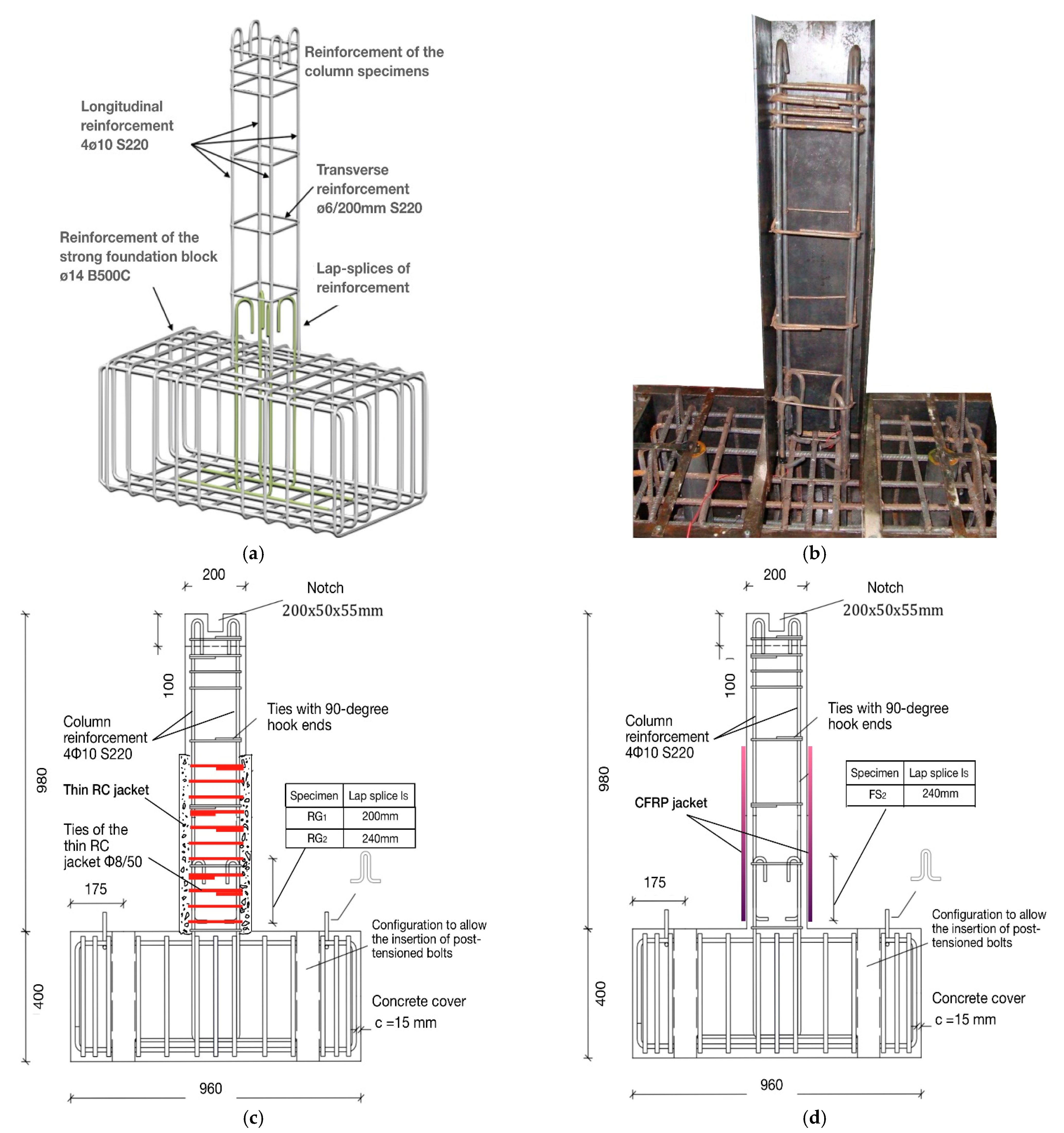
Figure 1.
Dimensions (in mm) of (a,b): the original specimens; (c) the strengthened with thin high-strength RC jacket specimens RG1 and RG2; (d) the strengthened with CFRP jacket specimen FS2.
Figure 1.
Dimensions (in mm) of (a,b): the original specimens; (c) the strengthened with thin high-strength RC jacket specimens RG1 and RG2; (d) the strengthened with CFRP jacket specimen FS2.

Figure 2.
Strengthening interventions (a) specimens RG1 and RG2: the concrete cover is chipped-away; (b) specimens RG1 and RG2: the ties of the thin high-strength RC jacket are placed in touch with the initial column; (c) specimen FS2: smoothening of the column surface and curving of the column edges; (d) specimen FS2: wrapping of the CFRP textile and full integration to the resin matrix.
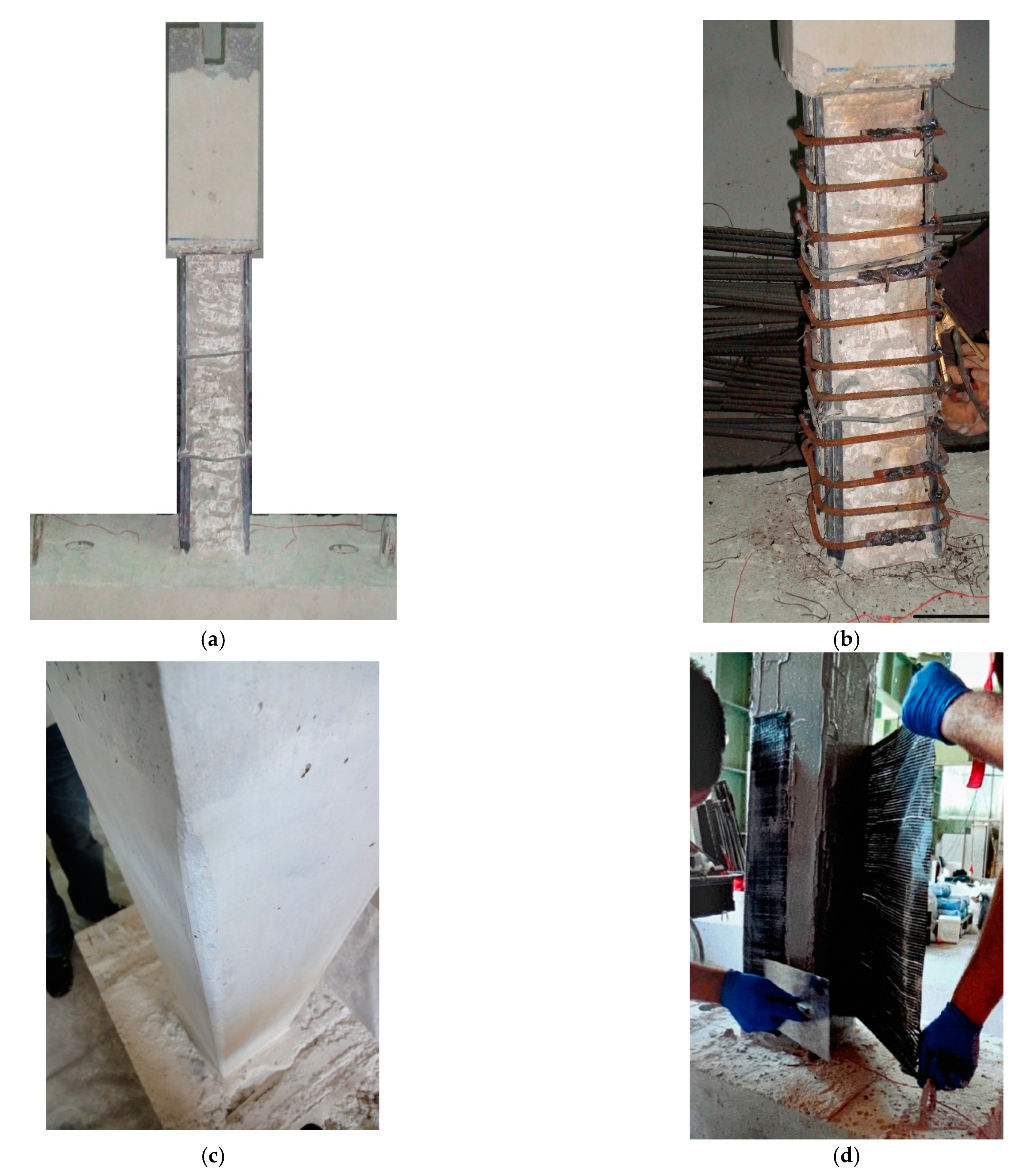
Figure 3.
Reaction frame and instrumentation.

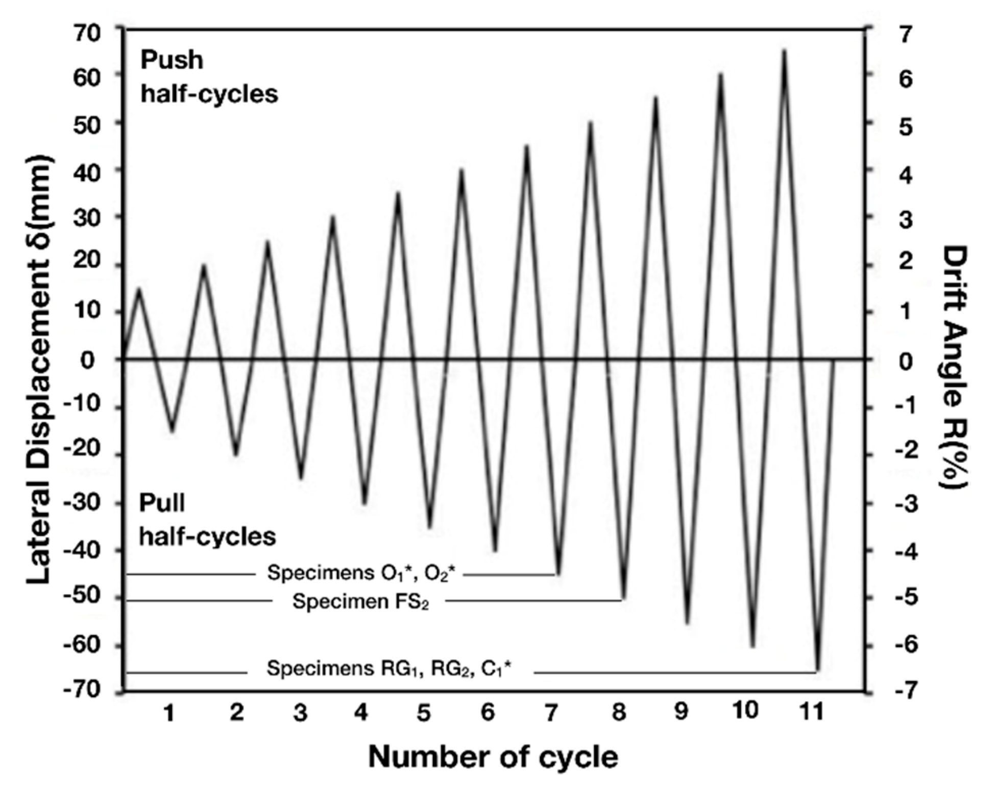
Figure 4.
Displacement-controlled schedule. *Specimens O1, O2 and C1 were tested in a previous work [3].
Figure 4.
Displacement-controlled schedule. *Specimens O1, O2 and C1 were tested in a previous work [3].

Figure 5.
Plots of resisted shear force-versus-displacement of the strengthened column specimens (a) RG1; (b) RG2; (c) FS2, (d) envelope curves. Specimens O1, O2 and C1 were tested previously [3].
Figure 5.
Plots of resisted shear force-versus-displacement of the strengthened column specimens (a) RG1; (b) RG2; (c) FS2, (d) envelope curves. Specimens O1, O2 and C1 were tested previously [3].
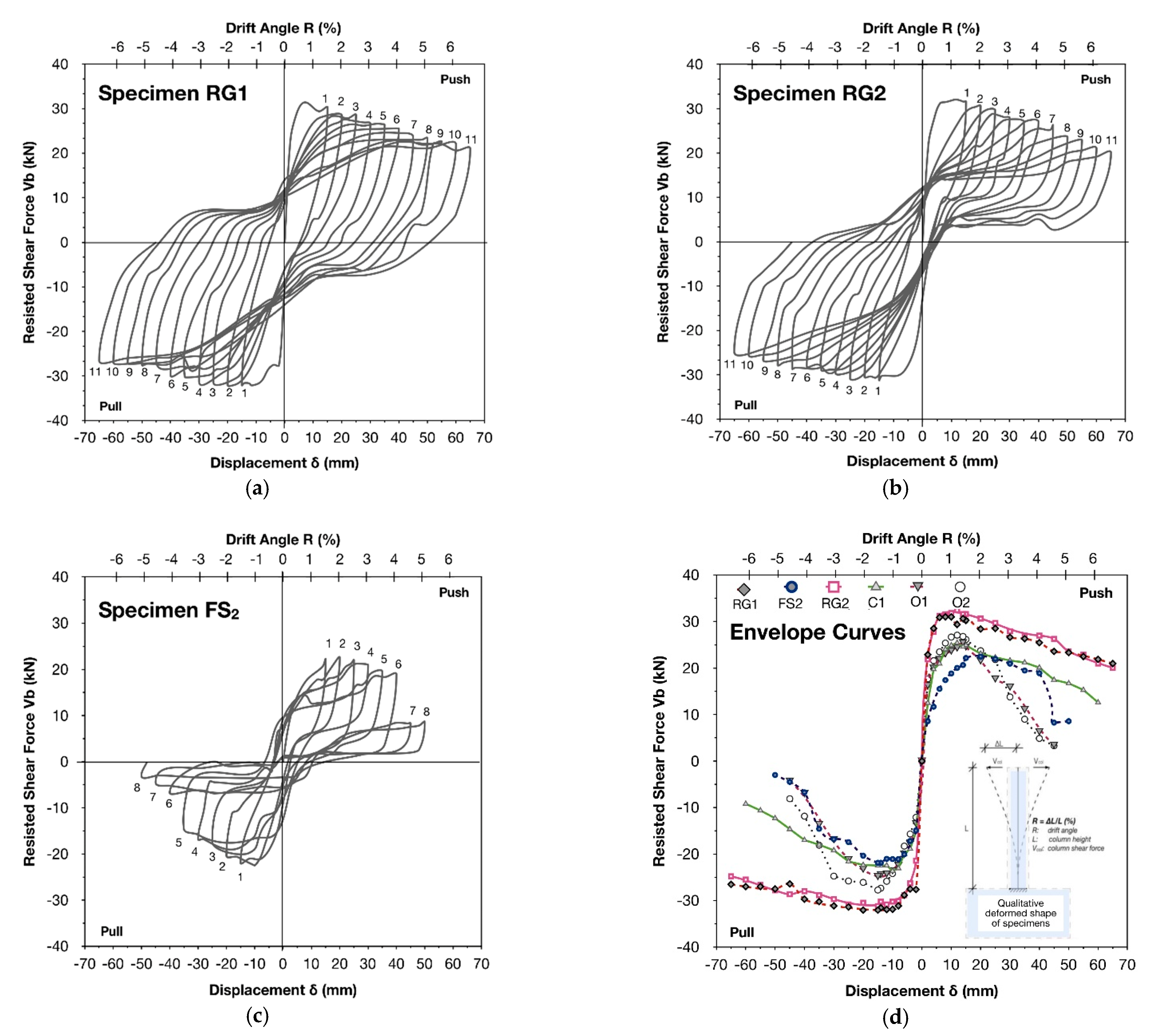
Figure 6.
(a) Peak-to-peak stiffness and (b) energy dissipation capacity of the strengthened specimens RG1, RG2 and FS2 with respect to specimens O1, O2 and C1 which were tested previously [3].
Figure 6.
(a) Peak-to-peak stiffness and (b) energy dissipation capacity of the strengthened specimens RG1, RG2 and FS2 with respect to specimens O1, O2 and C1 which were tested previously [3].

Figure 7.
Plots of (a) load point displacement-versus-strength ratio for peak displacement of each cycle and (b) load point displacement-versus-energy dissipation ratio for peak displacement of each cycle of the strengthened specimens RG1, RG2 and FS2 with respect to specimens O1 and O2 [3].
Figure 7.
Plots of (a) load point displacement-versus-strength ratio for peak displacement of each cycle and (b) load point displacement-versus-energy dissipation ratio for peak displacement of each cycle of the strengthened specimens RG1, RG2 and FS2 with respect to specimens O1 and O2 [3].

Figure 8.
Failure modes of column specimens (a) RG1 and (b) RG2 strengthened with thin high-strength RC jacket and (c) of specimen FS2 strengthened with CFRP jacket of two layers of textile.
Figure 8.
Failure modes of column specimens (a) RG1 and (b) RG2 strengthened with thin high-strength RC jacket and (c) of specimen FS2 strengthened with CFRP jacket of two layers of textile.
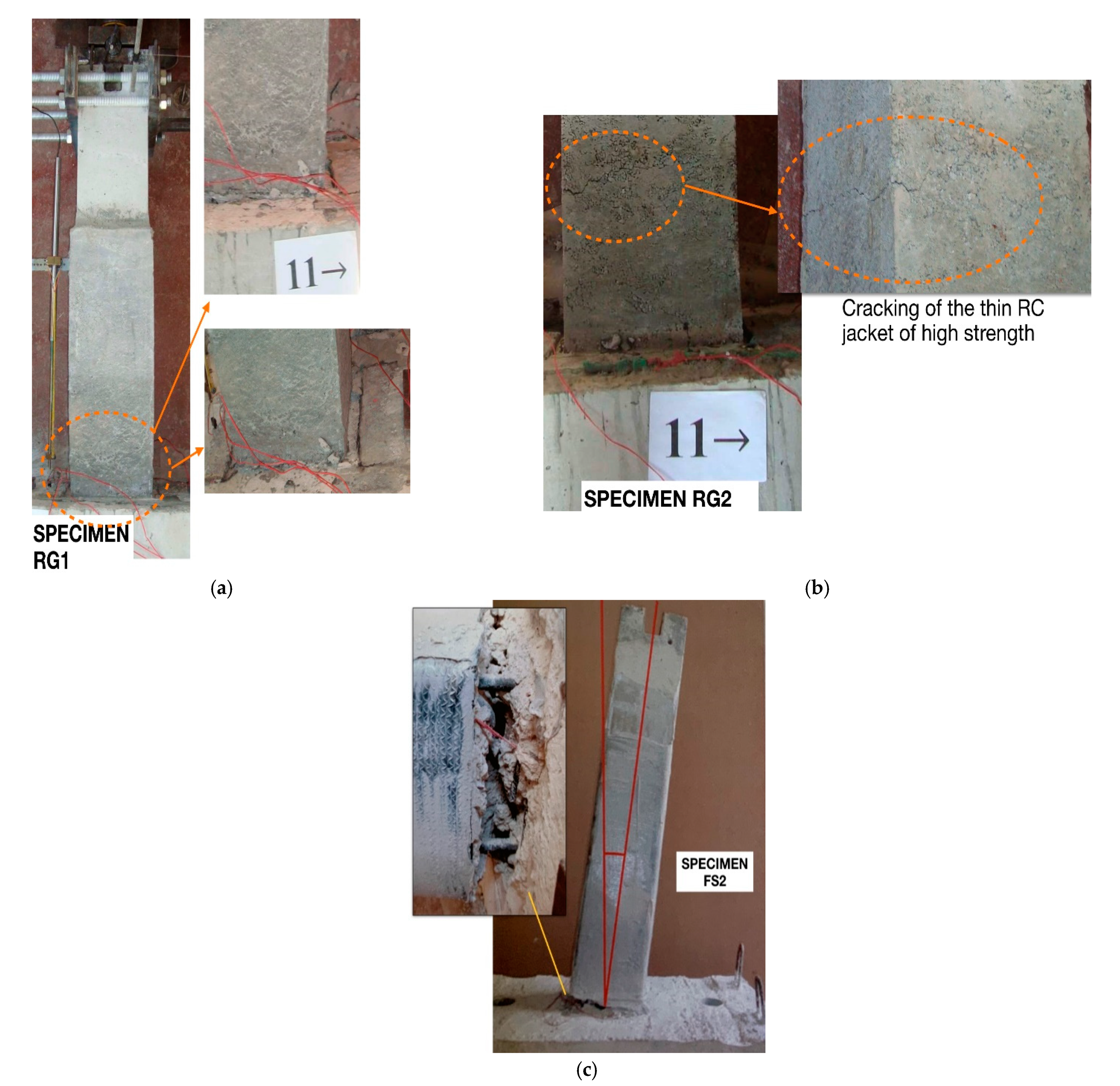
Figure 9.
(a) Equivalent viscous damping coefficient; (b) plots of energy dissipation capacity-versus-load point displacement-versus-equivalent viscous damping coefficient; (c) plots of cumulative energy dissipation-versus-load point displacement; (d) plots of cumulative viscous damping coefficient-versus-load point displacement of the strengthened specimens RG1, RG2 and FS2.


Figure 10.
Location of the strain gages (a) specimens RG1 (and RG2) and (b) specimen FS2.

Figure 11.
Plots of displacement-versus-strain-versus drift angle measured by strain gages which were attached on the steel bars of specimens RG1 (a–d); FS2 (e).
Figure 11.
Plots of displacement-versus-strain-versus drift angle measured by strain gages which were attached on the steel bars of specimens RG1 (a–d); FS2 (e).


Figure 12.
Maximum values of steel strain—specimen RG1.

Figure 13.
Formation of splitting cracks in the circumference of the bar due to the exhaustion of the concrete tensile strength.
Figure 13.
Formation of splitting cracks in the circumference of the bar due to the exhaustion of the concrete tensile strength.

Figure 14.
(a) Forces acting in the lap splice region through section I-I from the concrete compression strut mechanism; (b) annular critical regions and potential failure plane (KLMN).
Figure 14.
(a) Forces acting in the lap splice region through section I-I from the concrete compression strut mechanism; (b) annular critical regions and potential failure plane (KLMN).

Figure 15.
Experimental-versus-predicted values of shear stress in the lap splice region according to the proposed formulation.
Figure 15.
Experimental-versus-predicted values of shear stress in the lap splice region according to the proposed formulation.

Table 1.
Experimental program.
| Specimen | Lap Splice Length (mm) | CFRP Layers | Ties of Thin RC Jacket | Length of the Jacket (mm) | ||
|---|---|---|---|---|---|---|
| * C1 (control) | — | 10.25 | — | — | - | — |
| * O1 (original) | 200 | 9.81 | — | — | - | — |
| * O2 (original) | 240 | 8.80 | — | — | - | — |
| FS2 (strengthened) | 240 | 13.13 | 2 | — | - | max{lcr, 1.30•ls, 600 mm} = 600 |
| RG1 (strengthened) | 200 | 10.42 | — | 60 | Ø8/50 mm B500C | |
| RG2 (strengthened) | 240 | 9.72 | — | 60 | Ø8/50 mm B500C |
* Specimens O1, O2 and C1 were tested in a previous work [3].
Table 2.
Reinforcement of the column specimens.
| Specimens | * C1 | * O1 | * O2 | FS2 | RG1 | RG2 |
|---|---|---|---|---|---|---|
| Longitudinal reinforcement | 4Ø10 mm plain steel bars (= 374 MPa) | |||||
| Transverse reinforcement | Ø6 mm ties (plain steel) with 90° hook-ends spaced at 200 mm (= 263.5 MPa) | |||||
| Reinforcement of the thin high-strength RC jacket | — | — | — | — | Ø8/50 mm | Ø8/50 mm |
| Column cross-section (mm) | 200 × 200 | 200 × 200 | 200 × 200 | 200 × 200 | 203 × 203 | 203 × 203 |
* Specimens O1, O2 and C1 were tested in a previous work [3].
Table 3.
Material properties of the CFRP textile and the two-part epoxy resin.
| CFRP Textile | Epoxy Resin (Two-Part) | ||
|---|---|---|---|
| Jacket height (mm) | 600 | Life-time in container (min) for +20 °C | 35 |
| Weight (g/m2) | 200 | Pasting-time (min) for +20 °C | 45 |
| Modulus of elasticity Efib (GPa) | 235 | Minimum temperature for hardening (°C) | 8 |
| Tensile strength Ffib (MPa) | 3800 | Modulus of elasticity Efib (GPa) | 2500 |
| Eu (%) | 1.5 | Tensile strength Ffib (MPa) | 44.6 |
| Nominal width of textile (mm) | 0.11 | Eu (%) | 1.7 |
Table 4.
Predicted values of the concrete shear stress in the potential failure plane.
| Specimen RG1 | Specimen RG2 | |
|---|---|---|
| (Mpa) | 10.42 | 9.73 |
| (MPa) | 60.00 | 60.00 |
| (Mpa) | 0.63 | 0.53 |
| (Mpa) | 1.25 | 1.25 |
| (Mpa) | 0.63 | 0.53 |
| (Mpa) | 4.88 | 4.11 |
| (Mpa) | 9.68 | 9.68 |
| (Mpa) | 4.88 | 4.11 |
| (Mpa) | 4.88 | 4.11 |
| 1.00 | 1.00 | |
| 0.50 | 0.43 |
Publisher’s Note: MDPI stays neutral with regard to jurisdictional claims in published maps and institutional affiliations. |
© 2021 by the authors. Licensee MDPI, Basel, Switzerland. This article is an open access article distributed under the terms and conditions of the Creative Commons Attribution (CC BY) license (https://creativecommons.org/licenses/by/4.0/).
Share and Cite
MDPI and ACS Style
Kalogeropoulos, G.; Tsonos, A.-D. Seismic Performance Enhancement of RC Columns Using Thin High-Strength RC Jackets and CFRP Jackets. Fibers 2021, 9, 29. https://0-doi-org.brum.beds.ac.uk/10.3390/fib9050029
AMA Style
Kalogeropoulos G, Tsonos A-D. Seismic Performance Enhancement of RC Columns Using Thin High-Strength RC Jackets and CFRP Jackets. Fibers. 2021; 9(5):29. https://0-doi-org.brum.beds.ac.uk/10.3390/fib9050029
Chicago/Turabian StyleKalogeropoulos, George, and Alexander-Dimitrios Tsonos. 2021. "Seismic Performance Enhancement of RC Columns Using Thin High-Strength RC Jackets and CFRP Jackets" Fibers 9, no. 5: 29. https://0-doi-org.brum.beds.ac.uk/10.3390/fib9050029
Note that from the first issue of 2016, this journal uses article numbers instead of page numbers. See further details here.