
A Domain-Specific, Model Based Systems Engineering Approach for Cyber-Physical Systems


Josef Ressel Centre for Dependable System-of-Systems Engineering, Salzburg University of Applied Sciences, Urstein Sued 1, A-5412 Puch, Austria
*
Author to whom correspondence should be addressed.
Systems 2022, 10(2), 42; https://0-doi-org.brum.beds.ac.uk/10.3390/systems10020042
Submission received: 17 February 2022
/
Revised: 18 March 2022
/
Accepted: 24 March 2022
/
Published: 26 March 2022
(This article belongs to the Section Systems Engineering)
Abstract
:Model Based Systems Engineering as a scientific discipline tries to address the increasing complexity of today’s cyber-physical systems by utilizing different kinds of models. In practical application, however, this approach is often constrained to SysML-based object modeling. Even though this appears to be a suitable approach for dealing with complexity, various restrictions limit stakeholder acceptance. Considering scientific discussions in the context of modeling shows two different schools of thought. On the one hand, arguments for more formalized and rigorous concepts can be found, where on the other hand, the need for more stakeholder-oriented and easier-to-understand concepts is postulated. As both are reasonable, the question of integration arises. To address this aspect, we developed the concept of Domain Specific Systems Engineering. Our research in this field lasted for nearly a decade, and different aspects have been investigated. This paper contributes a summary of the overall approach that integrates the various aspects investigated so far. Thus, the underlying concepts are explained, and the corresponding modeling stack and tool-chain are described in more detail. Further, the practical experiences from various case studies are summarized, and identified shortcomings are discussed.
1. Introduction
Development and deployment of cyber-physical systems (CPS) as integrations of computation and physical processes where embedded computers and networks monitor and control the physical process [1] proceed at a fast pace. Aside from the increasing availability of affordable hardware, software-related technologies (e.g., Artificial Intelligence (AI)) and increasing connectivity (e.g., 5G) can be identified as drivers. As these emerging technologies—and especially their integration—represent a promising potential for new products and services, the application field for CPS is vast. Typical application domains are Automotive Engineering, Industry 4.0, Smart Grid, or Smart Cities.
Development of CPS, however, is challenged by the inherent complexity of individual systems and their integration in a superordinated application scenario. The classification as complex systems in that sense relies on a qualitative classification scheme proposed by Haberfellner et al. [2]. This classification scheme is based on the two dimensions diversity/variety/scale and dynamic/alterability and considers systems as either simple, complicated, dynamic, or complex. Even though the Haberfellner concept is rather a thought model, it can be a valuable starting point for identifying suitable engineering approaches.
To take the aspect of cooperative behavior between systems into account, the term System-of-Systems (SoS) is used. A frequently used definition in literature (original author not verifiable) defines a SoS as “a collection of task-oriented or dedicated systems that pool their resources and capabilities together to create a new, more complex system that offers more functionality and performance than simply the sum of the constituent systems“. Even though alternative definitions exist (e.g., [3,4,5,6,7,8]), broad consent exists on the characterization of SoS on basis of the Maier-DeLaurentis criteria (operational and managerial independence, evolutionary development, emergent behavior, geographical distribution, interdisciplinary, heterogeneity, networks of systems) [9,10]. These criteria do not only indicate a close relation between CPS and SoS; rather, they already highlight some particular challenges in the development of CPS.
Asides the promising capabilities of CPS, some critical aspects need to be taken into account. From a control systems perspective, the ongoing trend towards “fully automated” represents closed-loop scenarios with no human control instance as fall-back scenario anymore. Consequently such CPS are challenged by the need for fulfilling strict dependability requirements [11]. Countless publications have been considering aspects such as resilience, robustness, safety, security and others in different application domains such as the Smart Grid [12,13,14,15,16], Smart Cities [17,18,19,20,21], Automotive [22,23,24,25,26,27], or Industry 4.0 [28,29,30,31,32].
A widely used taxonomy in that context has been proposed by Avizienis et al. where dependability is interpreted as an umbrella term for the individual characteristics Reliability, Availability, Maintainability, Safety, and Security [33]. In context of CPS where personal data can be involved (e.g., Electric Vehicle charging) Neureiter et al. suggest to also consider Privacy in this context [34].
The integration of dependability is severely challenged by the increasing complexity of CPS as outlined before. In context of Security for instance, Schumacher highlights complexity as the enemy of security [35]. Though this statement relates to security it appears valid to extend this conclusion to the whole spectra of dependability.
As dependability characteristics are observed on system-level, consent exists that they need to be considered by design, or as stated by Avizienis, through the combination of fault prevention, fault tolerance, fault removal, or fault forecasting techniques [36]. The ability to establish a holistic and shared understanding of a system among all involved stakeholders from all disciplines is imperative in that case. A significant barrier for this, however, is the lack of concepts for establishing a common, interdisciplinary system understanding in the field of CPS. Thus, today System-of-Systems Engineering (SoSE) (with its apparent relation to CPS) is considered a critical research discipline for which—as stated by Popper—frames of reference, thought processes, quantitative analysis, tools, and design methods are incomplete [37]. A similar conclusion, in that case, has further been drawn by Edward Lee, who summarizes the challenges to be addressed as follows [38]:
- Determinate CPS models;
- Open minds about languages and tools;
- A semantics of time;
- Discipline of “model engineering”.
Based on the ongoing discussion, it appears safe to conclude that today’s engineering approaches require improvement for enabling a holistic understanding of CPS that anticipates all involved stakeholder perspectives. This aspect is deemed crucial to further allow for the integration of dependability by design.
The quest for holistic engineering approaches is mainly pursued by the Systems Engineering (SE) community. Main focus in SE, however, lies on the process perspective as described by International Council on Systems Engineering (INCOSE) [39] or ISO 15288 [40].
For managing the complexity of CPS the utilization of models appears to be a feasible approach. Several authors argue that SE goes hand in hand with Model-Driven Engineering (MDE) [41,42,43,44]. Unfortunately, the terminology in the context of model-driven approaches is ambiguous as this topic evolved, mainly driven by the field of Software Engineering. A clarification of the terminology can be found, for example, in [45].
To give better guidance for SE, INCOSE ultimately defined the term Model Based Systems Engineering (MBSE) as “The formalized application of modeling to support system requirements, design, analysis, verification and validation activities beginning in the conceptual design phase and continuing throughout development and later life cycle phases.” [46].
Although the need for modeling is consented to within the SE community, conceptual descriptions stay rather vague and lack guidelines for application. Thus, the application of MBSE is often constrained to object modelling by means of Systems Modeling Language (SysML) [47].
Even though the utilization of Object Models for decomposing complex systems is a common concept in Software Engineering, the practical application in Systems Engineering stays behind expectations. One explanation can be found in the Software Engineering background of this concept. Especially the utilization of concepts such as Object Oriented Analysis or the usage of General Purpose Languages (GPL) such as SysML are identified as significant barriers for engineers with no Software background. Another limitation can be found when it comes to integrating particular design models, such as a schematic of an electric power grid, which is not considered a straightforward task.
The ongoing discursus in the context of CPS development shows consent on the need for enforced anticipation of models. Still, significant discussions take place on the question of which models are to be used. Literature research yields two different schools of thought in that debate. In the context of MDE, for example, Favre criticizes that though MDE is supposed to be about precise modeling, MDE core concepts are not defined through precise models. One can find plenty of metamodels in the literature to describe particular technologies or tools, but we are not aware of a single one that fully captures the MDE notions at a global level [44]. Even though stated for MDE, this statement appears valid for MBSE as well.
A statement from Edward Lee contrasts the given criticism. The latter argues that “the role that models play in engineering is different from the role they play in science, and that this difference should direct us to use a different class of models, where simplicity and clarity of semantics dominate over accuracy and detail” [48].
Reflecting these two points of view, one can conclude that both have their justification. On the one hand, precise and formal models could contribute to engineering dependability by design but probably would pose a high entry barrier for several stakeholders. On the other hand, models putting simplicity and clarity in the foreground would lower the entry barrier but the suitability for engineering dependability by design could be limited. Thus, the question is rather not about one or the other; instead, it is about a combination of both approaches to establish a holistic system understanding as a basis for engineering dependability by design.
Concerning the outlined discussion, the main goal of the proposed Domain Specific Systems Engineering (DSSE) approach can be postulated: DSSE envisions a holistic MBSE approach for CPS that enables the establishment of a holistic system understanding as a basis for engineering dependability by design. To do so, similar to the concept of Domain Driven Design (DDD) [49] known from Software Engineering, this approach fosters a polarized perspective by separating a domain perspective from a staged technical perspective. In this context, the domain perspective is related to a particular application domain (e.g., Smart Grid) and aims at establishing a common understanding among all involved stakeholders. Complementary, the technical perspective aims at structuring and integrating all involved engineering disciplines such as electrical engineering, mechanical engineering, software engineering, and others.
The envisioned approach consists of several bits and pieces targeting different aspects. Exemplary artifacts are a modeling stack, several Domain-Specific Languages (DSLs), process models, modeling tools, or concepts for tool-chain integration. Since 2012 different aspects of DSSE have been investigated in detail. The goal and contribution of this paper are to integrate all the individual bits and pieces of DSSE and to outline how their integration contributes to the realization of the DSSE vision.
Thus, the remainder of this paper is structured as follows. Section 2 discusses established approaches and outlines how DSSE addresses existing shortcomings. In addition, Section 3 illustrates the research design and validation strategy our work is based on. The key concepts of DSSE and the integration of the main building blocks are outlined in Section 4, followed by a more detailed description of the developed modelling stack (Section 5), the Domain Specific Language (DSL) (Section 6), and the established tool chain (Section 7). A critical reflection on the proposed concept is further provided in Section 8, followed by a summarizing conclusion in Section 9.
2. Background and Own Contribution
For interdisciplinary development of dependable cyber-physical systems (CPS), the utilization of models is inevitable. As discussed in Section 1, different schools of thought argue in favor of different strategies. Formalization and the need for a certain rigor are demanded by the one side, simplicity and understandability by the other.
Thus, in the following popular modeling approaches from the field of MBSE are outlined, followed by complementary concepts focusing on understandability and clarity. Further, the DSSE approach is put in this context, and its contribution is highlighted.
2.1. Modeling Approaches
In context of architecture development the utilization of object models is common with SysML as predominant modeling language. Designed as General Purpose Language (GPL), SysML provides a variety of diagram types to model any system, yet its scope does not cover strategies for model development or their organization.
Related process concepts, as proposed for example by ISO 15288 [40], are rather generic. As depicted in Figure 1, ISO 15288 summarizes several processes to be considered in Systems Engineering but does not deliver a detailed process model. Rather, in respect to the varying nature of different systems, it is suggested to taylor this framework according to the individual needs.
For the particular aspect of modeling, different approaches are known that help structuring and organizing both the process of architecture development and the organization of models. Some popular proponents are for example the Twin-Peaks pattern proposed by Nuseibeh [50], Weilkiens’s SYSMOD approach [51], or the SPES 2020 methodology [52,53] that gained momentum in the recent past.
The mentioned approaches vary in focus and granularity. Twin-Peaks, for example, introduces a fundamental pattern for simultaneous development of problem and solution space. This pattern is further extended by the SYSMOD approach (“SYSMOD Zigzag Pattern”) and embedded within a more holistic yet pragmatic modeling approach.
A more recent approach is the SPES 2020 methodology introducing a more sophisticated modeling concept for embedded systems. The mission of SPES 2020 has been described as the development of “A model-driven, and tool-supported approach that is based on a strong mathematical foundation [that] allows for the efficient development of embedded systems, starting with initial customer requirements, through specification of architectures, through implementation, to system verification and certification” [52] (p. 9).
The main aspect of SPES 2020 is the approach to structure architecture development on basis of four individual viewpoints and on different abstraction levels as depicted in Figure 2. Further, every viewpoint comprises different model kinds used to describe particular artifacts. For example, the Requirements Viewpoint could involve User Stories, Use Cases, or SysML Requirements models, the Function Viewpoint typically consists of a functional decomposition, whereas the Logical Viewpoint and the Technical Viewpoint model the logical respectively the physical structure of a system.
All outlined approaches have to be acknowledged as significant contributions to the field of MBSE. However, it must be mentioned that the utilization of these concepts comes with the prerequisite of a basic understanding of the underlying concepts of MBSE. Thus, application is mainly driven by System Architects, and acceptance among other stakeholders poses a significant challenge. This aspect is a severe limitation, especially during the early stages of system analysis or SoS design.
2.2. Domain Specific Architecture Frameworks
The outlined, formalized concepts originating from MBSE are contrasted by different attempts aiming at understandability and clarity. A popular case in that context can be found, for example, in the Smart Grids application domain. Development of Smart Grids, as the integration of power grids with Information and Communication Technologies (ICT), raises the need for alignment of concepts from both disciplines, electrical engineering and telecommunication.
An initial attempt for establishing an integrated perspective has been made by the standardization bodies European Committee for Electrotechnical Standardization (CENELEC) and European Telecommunications Standards Institute (ETSI). Following the intention of aligning electrotechnical and ICT related standards, in 2012, the Smart Grid Architecture Model (SGAM) has been proposed as a tool for reference designation in the Smart Grid [54]. The SGAM can be interpreted as an architecture framework that allows for a structured representation of Smart Grid components and functionalities covering both the electrotechnical and ICT dimension.
As depicted in Figure 3, the SGAM consists of five layers with a grid pattern structure. The grid pattern of every layer is built upon Domains that are decomposing the problem domain (electrical power chain) on the one hand, and the automation of the power grid (Zones) on the other hand. The resulting structure can be seen as a coordinate system for locating different elements within the overall Smart Grid. Complementary to this structure, the individual layers allow for consideration of various aspects such as the regulatory envelope (Business Layer), functionality (Function Layer), or different technical aspects (Information, Communication, and Component Layer).
The concept of SGAM has turned out to be of value in terms of understandability, especially when it comes to interdisciplinary cooperation. Thus, it exceeded its original scope and has been used as a basis for architecture development on a higher level in numerous scientific and industrial projects. A recently published overview on the application and impact of SGAM can be found, for example, in [55]. Furthermore, the ideas of SGAM have been anticipated and transferred to several complementary domains. Examples are the Reference Architecture Model Industry 4.0 (RAMI 4.0) [56], Reference Architecture Model Automotive (RAMA) [57], Maritime Architecture Framework (MAF) [58], Generic Smart City Architecture Model (GSCAM) [59], or the Electric Mobility Architecture Model (EMAM) [60].
All concepts mentioned above, especially those originating from standardization bodies (SGAM, RAMI 4.0), are distinct by their understandability for domain stakeholders and, thus, find a certain acceptance. However, it has to be admitted that these concepts are not grounded on a formal basis, which limits their applicability in a holistic engineering process, covering all stages of architecture development.
2.3. Contribution of DSSE
In the development of dependable CPS, the need for formalization arises to achieve a seamless and holistic design, development, and validation process. This approach comes at the price that all involved stakeholders need to be familiar with MBSE in general and modeling in particular.
By reflecting the benefits and broad acceptance of informal, yet domain-specific architecture frameworks, the DSSE approach strives for a shift in paradigms. Instead of requiring all stakeholders to familiarize with MBSE, DSSE raises the plea for modeling approaches to adapt to the stakeholder’s perspective. To be more precise, formalized modeling should be enabled in the stakeholder’s lingua franca instead of forcing stakeholders to learn modeling languages such as SysML. Thus, DSSE provides a formalized modeling approach that is grounded on the application domain, as the name suggests.
The contribution of the DSSE approach as a whole can be considered in two aspects, as delineated in Table 1. The first aspect is the philosophy that modeling approaches should not be driven by the systems to be developed but by the stakeholders being involved. The second aspect is the contribution of different bits and pieces such as a modeling stack, a DSL, several elements of a holistic tool-chain, validation concepts, and others that help to realize this philosophy.
Our research on DSSE lasted for nearly ten years and various elements have been studied in detail. The paper at hand is intended to integrate all these aspects and outline the overall picture. It is designed to be the umbrella showing how the individual elements of our past research fit together and serve the realization of the DSSE modeling philosophy.
3. Research Design and Validation Strategy
The validation of engineering approaches is a challenging task. For sound results, industrial long-term field studies of significant scale would be required. When it comes to developing yet-to-come systems such as the Smart Grid, things become even more complicated. Due to the novelty of these systems, no such thing as a “ground truth” for comparison exists. Research in this context is characterized by simultaneous learning in both the problem space and the solution domain.
A reasonable attempt for dealing with this challenge can be found with the Agile Design Science Research Methodology (ADSRM) as proposed by Conboy et al. [61]. In this approach, Conboy extends the widespread Design Science Research Process (DSRP) from Pfeffers et al. [62] with concepts from agile software development. It intends to combine the flexibility from agile concepts with the necessary level of rigor as required by design science.
As depicted in Figure 4, the primary research paradigm of ADSRM is a staged approach with different entry points. Contrasting to the classic DSRP, the individual sub-processes are intended to be executed in a fast and iterative manner (“sprints”), which enables incremental learning and development. Instead of trying to fix all research objectives initially, it emphasizes starting with a rather vague research topic that is refined into particular research goals during the execution of iterative sprints. Further, new challenges identified can be added to the “Problem Backlog” for later investigations.
After achieving a certain level of understanding of the problem on the one hand, and ideas for possible solution artifacts on the other hand, ADSRM integrates the necessary level of rigor employing so-called “hardening sprints”. During these hardening sprints, (1) the problem and (2) the process are frozen, and (3) additional rigor-driven parts such as extra measures or changes of the existing measures shall be added to the process [61]. Evaluation of particular artifacts finally can be done by application of classic design science concepts such as the evaluation methods (observational, analytical, experimental, testing, descriptive) proposed by Hevner et al. [63].
With the ADSRM concepts for agile research in mind, our research on the DSSE approach can be separated into three stages that are executed in an iterative manner as depicted in Figure 5 and described in the following.
Problem Exploration: This stage strives for the establishment of a better problem understanding and is rather a continuous task than a strictly limited phase. In general, exploratory case studies (e.g., in the context of different research projects) are used to identify particular challenges on a higher level. These challenges are further collected and structured within the Problem Backlog as input for more focused research. Elements of the backlog are, for example, “How to foster a better stakeholder participation during architecture development?” or “How to enable System-of-Systems (SoS) validation in electric vehicle charging scenarios?”.
Artifact Development: During this stage, particular research items from the backlog are isolated, research questions and objectives are postulated, and particular artifacts are designed and implemented. Objectives specified during this phase are for example "enable a seamless model development that integrates (1) SGAM concepts and (2) established architecture frameworks" or "enable the integration of architectural models with Co-Simulation frameworks". On this basis, subsequently individual artifacts such as the DSS modeling stack, a corresponding DSL, the SGAM Toolbox implementation, or an integrated tool-chain are designed and implemented. At this point it has to be mentioned that every iteration does not necessarily yield a new artifact, rather every iteration contributes to the refinement of the main artifacts. For example, the already existing DSL is adopted by altering its integrated viewpoints and model kinds.
Evaluation and Validation: The third stage aims at the evaluation of the previously developed artifacts. Thus, the modeling concepts (implemented artifacts) from the DSSE Approach are used to create a model of the specified case study and the suitability of the individual artifacts is evaluated in respect to the previously specified objectives. Identified shortcomings during the application are observed and contribute to an extension of the problem backlog. Further, these observations can be used to drive adaptations of the utilized case study for further investigations.
The chosen research approach comes with two risks. First, as development and evaluation (hardening sprints) are done on basis of the same case study, the risk of a bias exists, e.g., developed solutions are only suitable for the particular case study. Second, as the research subject is related to engineering methods, validation by engineers different from the developers of the concepts needs to be considered.
To limit the impact of these aspects, an evaluation strategy is maintained that rests on five pillars:
- Implicit evaluation: The hardening sprints of ADSRM are considered as “implicit” evaluation indicated by the chosen research design;
- Complementary case studies: Developed artifacts are applied to case studies of a complementary application domain. E.g., Co-Simulation related artifacts developed in the application domain Smart Grid are applied to case studies from the application domain Industry 4.0;
- Third party application: To gain feedback of the developed concepts, the main artifacts (e.g., SGAM Toolbox: www.sgam-toolbox.org (accessed on 16 February 2022), RAMI Toolbox: www.rami-toolbox.org (accessed on 16 February 2022)) have been made publicly available. Furthermore, extensive support has been provided that in return delivered insights on the applicability of our concepts for third party engineers;
- (Quantitative) Impact Evaluation: For the application of the developed artifacts, different video tutorials were created. The viewer statistics (e.g., viewers, time, location) have been tracked and evaluated as an indicator for the significance of the developed DSSE approach;
- Scientific Publications: Publishing of peer-reviewed articles provides detailed feedback from reviewers and indicates the significance based on citations. At present, around 30 peer-reviewed articles in the context of DSSE have been published.
A more detailed discussion on the validation strategy with additional information (e.g., quantitative analysis and interpretation of the video tutorial statistics) is presented in [64].
The described research design outlines how the overall DSSE research is drilled down into separate research items that have been investigated individually. At this point, it has to be stressed again that the intention of the paper at hand is to summarize and generalize the main building blocks (individual research items) and to illustrate the integration of these particular items for the purpose of realizing the overall DSSE philosophy.
4. The Domain Specific Systems Engineering Approach
As outlined in Section 1, the DSSE approach aims at providing a modeling concept that is both easily accessible for heterogeneous stakeholders and precise enough to enable rigorous development. For this purpose a modeling stack is developed that separates Domain Architecture, Technical Architecture and Design Models. Further, this modeling stack is accompanied by a process model and a modeling environment.
The present section gives an overview of these building blocks and their interrelations.
4.1. Modeling Stack
The modeling stack comprises a 3 + 1 layer architecture reflecting the structure of Model-Driven Architecture (MDA), which has been proposed by Object Management
Group (OMG) [65]. The software-originated MDA approach focuses on a separation of functionality and technology which is done by introducing four abstraction layers. The top-level layer, entitled as Computational Independent Model (CIM) focuses on a functional analysis of a system that is subsequently mapped onto a technical yet technology-neutral layer (Platform Independent Model (PIM)). Next, elements from the PIM are allocated to particular technology on the level of the Platform Specific Model (PSM) which ultimately defines the implementation (Platform Specific Implementation (PSI)). The interrelation between the individual modelling layers requires a more differentiated discussion as the type of interrelation depends on the nature of the corresponding levels. A detailed discussion on the modeling stack, its individual layers and interrelations is presented in Section 5.
Contrasting to MDA, the DSSE approach does not concentrate on (semi-) automatic model transformations, rather it reflects its intention for separation of concerns. Thus, four layers are defined and for every layer a certain set of viewpoints is specified in accordance with the concepts of ISO 42010 [66]. As depicted in Figure 6, every viewpoint is intended to address particular concerns of certain stakeholders. Further, for every viewpoint a set of corresponding model kinds is specified. This specification finally governs the particular views and models created within a particular architecture description.
An overview of the modeling stack, built upon the four layers of MDA and the concepts of ISO 42010 is depicted in Figure 7.
4.2. Modeling Environment
To enable a practical application of the theoretical DSSE concepts, a certain modeling environment has been established. The critical element of this modeling environment is the specification and implementation of a DSL, taking the viewpoints and model kinds from the modeling stack into account. This DSL enables a seamless development of the Domain Architecture Model with the Technical Architecture Model. Further, concepts are provided for the hand-over to the Detailed Design Model.
The described DSL is implemented as SysML profile to exploit the fundamental concepts of object modeling. To compensate for the profile mechanism’s limitations, Add-Ins have been implemented for different commercial modeling tools. These Add-Ins integrate the DSL and add additional functionality such as semi-automatic model transformations. Furthermore, import and export mechanisms are realized that enable, for example, the integration with co-simulation environments for validation.
4.3. Process Model
To give guidance for modeling, the DSSE approach proposes a process model comprising the three primary phases System Analysis, System Architecture, and Design and Development. The System Analysis phase aims at understanding the system to be built and yields the Domain Architecture Model. This phase is typically driven by a requirements engineer and involves all stakeholders. Subsequently, the System Architecture phase is intended to decompose particular systems into their individual design elements. Finally, these design elements are handed over to engineers from various disciplines who create the Detailed Design Model and implementation.
5. The DSSE Modeling Stack
The modeling stack of the DSSE approach consists of the three layers Domain Architecture, Technical Architecture, and Detailed Design. Every layer addresses different concerns and consists of several viewpoints. Moreover, every viewpoint is associated with particular model kinds. For the upper two layers, a DSL is specified and implemented, which will be discussed in the subsequent section.
5.1. Domain Architecture Model
The Domain Architecture Model is intended to identify the overall system topology and its functionality on a high level. As this task involves various stakeholders with heterogeneous backgrounds, the main challenge is establishing a common modeling language. The least common denominator between all stakeholders is the particular application domain of a system, such as Industry 4.0 or Smart Grid. For this reason, in the first step, the lingua franca of a specific application domain needs to be identified before, in a second step, particular viewpoints and model kinds can be derived.
To increase the chance of acceptance, the DSSE approach tries to utilize existing Reference Architecture Models such SGAM, RAMI 4.0, and others (see Section 2).
For developing the Domain Architecture Model, three viewpoints have been established. The Enterprise viewpoint addresses business-related aspects such as identification of business goals, description of business processes, or identification of the legal envelope. The functionality of a system is considered by the Function viewpoint, and technical concerns can be addressed within the Technical Concept viewpoint.
As suggested by ISO 42010, every viewpoint is further associated with particular model kinds which can be understood as the “language” being used to populate a viewpoint. At this point, domain-specific concepts (stakeholder’s lingua franca) can be utilized. An example for the application domain Smart Grid is illustrated in Figure 8. As can be seen, the individual layers of the SGAM are interpreted as model kinds that are used to populate the previously defined viewpoints.
At this point, however, it needs to be mentioned that the original intention of SGAM was to help to identify gaps in standardization. It was not developed as a framework for architecture development. Thus, aspects such as requirements have not been considered, making it necessary to integrate additional viewpoints and model kinds regarding a project’s specific character.
In early attempts, the SGAM layers were considered as individual viewpoints. This attempt had to be reconsidered to better reflect the evolution of the used model elements as depicted in the lower part of Figure 8. As can be seen, in a first step Business Actors are used to analyze enterprise concerns [64]. These actors are subsequently allocated to Logical Actors for the specification of functionality. The allocation relation clarifies the responsibility for every Logical Actor. Finally, Logical Actors are allocated to particular Components. Here it is important to notice that the same model elements (“Components”) are being used in all three model kinds of the Technical Concept viewpoint.
A central question of this approach is the question of which model kinds to be used. For different aspects such as business process modeling or physical (electrical) composition, standardized concepts (e.g., Business Process Modelling Notation (BPMN), electric schematics,...) exist. Other aspects (e.g., network topology) are less standardized, but iconic representations are widespread. The strategy of DSSE in that case is to introduce a limited set of modeling elements as an umbrella and link those elements to commonly used concepts. For example, the elements Business Process and High Level Use Case are introduced. For a more detailed description of these elements, integration is provided with BPMN or the IEC 62559 Use Case template [68].
The definition of the discussed model kinds has been done by developing a DSL which is discussed in the following section in detail. However, the specification of modeling elements, their semantic meaning, and iconic representation remains a critical aspect that would benefit from a consolidated concept, preferably proposed by standardization bodies.
5.2. Technical Architecture Model
The outcome of the Domain Specific Model is the identification of particular components with well-defined ownership, functionality, and technical interfaces. Subsequently, these components can be decomposed into their design elements within the Technical Architecture Model. This task is typically executed by a system architect.
In context of DSSE the application of the Software Platform Embedded Systems (SPES) methodology [52,53] is suggested which gained momentum in the recent past. As already introduced in Section 2, the backbone of the SPES methodology is the specification of the four viewpoints Requirements, Function, Logical Architecture, and Technical Architecture. In context of these viewpoints, an iterative and incremental decomposition of the component can take place that specifies requirements, functionality, and structure on different levels (Figure 2).
As the task of system decomposition reflects the object-oriented paradigm, the application of SysML as dominant systems modeling language appears natural. Before applying SysML, however, the aspect of function development needs to be considered as SysML today lacks a concept for developing and modeling functions - a central element of SPES.
A suitable approach to deal with this aspect is delivered by the Functional Architecture for Systems (FAS) methodology proposed by Lamm and Weilkiens [69]. This approach introduces a concept for developing and modeling particular system functions based on different Use Cases. For this purpose, FAS combines standard SysML elements (e.g., Use Cases or Activities) with additional ones such as function or function groups. The specification of these additional elements is done by a metamodel, complemented with a publicly available SysML profile (http://fas-method.org/ (accessed on 16 February 2022)).
5.3. Detailed Design Model and Implementation
The iterative decomposition of components ultimately yields particular design elements such as electric circuits, software, or mechanical parts. These elements are intended to be passed to engineers from the corresponding discipline for creating the detailed design (Detailed Design Model) and implementation.
An important aspect, in that case, is to enable traceability between different elements. A simplified example shall illustrate this aspect. It’s assumed that a charging station is decomposed into a mechanical design element (housing) and an electrical design element (main circuit). Both elements are considered to be developed individually by a mechanical and electrical engineer. The electrical design element is further characterized by attributes such as power and efficiency coefficient. However, changes in the efficiency coefficient during development could affect the thermal behavior, which should be reflected by the housing’s mechanical design.
A common difficulty in engineering is the communication between engineers from different disciplines. Often, this aspect solely relies on personal relations and experience. For the outlined example, the correlation is obvious, but considering factors such as Noise/Vibration/Harshness (NVH), privacy, or maintainability illuminates the need for more rigorous concepts. To address this aspect, the DSSE approach introduces the two specialized model elements Design Element and Design Parameter. As illustrated in Figure 9, the last stage of decomposition consists of Design Elements, which further comprise different Design Parameters specified by a specific value (or a bandwidth). Further, interdependencies between individual Design Parameters and other Design Elements can be modeled using a trace relation.
The architect who maintains the system-wide perspective can now hand over individual Design Elements (together with the predefined Design Parameters) to the corresponding engineers. When changes or deviations from these Design Parameters are required, possible interdependencies can be analyzed and handled accordingly on the architectural level.
5.4. Interrelations between the Different Layers
The interrelations between the different layers of the modeling stack require a more differentiated discussion as they depend on the nature of the individual layers. As depicted in Figure 10, the top layer (Domain Architecture) is created by means of a specific DSL (see Section 6) and implemented as SysML Profile. Thus, elements on this level basically are SysML Blocks extended by a specific stereotype.
As the Technical Architecture Model is built upon SysML as well, the upper two layers can be created within one single modeling tool, or within one particular model. From a technical point of view the decomposition task could be performed directly on basis of the modeling element from the Domain Architecture Model. In this scenario, however, the question occurs in which of these two layers the component should be located.
To maintain a strict separation between the Domain Architecture Model and the Technical Architecture Model it is suggested to include an explicit model-to-model transformation. Technically, this implies the integration of one component (Stereotyped SysML Block) within the Domain Architecture Model, a second component (plain SysML Block) within the Technical Architecture Model, and a Model Transformation relation in between.
For the interrelations between the Technical Architecture Model, the Detailed Design Model, and the physical artifacts some more project specific considerations are necessary. As previously illustrated in Figure 9 at this stage a hand-over between a System Architect and different Design Engineers with individual tools (e.g., schematic editor, CAD tool, Software Development) takes place. The focus here is to maintain traceability between architectural models and design models. As this typically involves multiple tools with different interfaces, this task needs to be considered individually within the particular project and tool-chain configuration management.
6. Domain Specific Language
To enable the application of the DSSE modeling stack, a DSL has been developed covering the Domain Architecture Model and the Technical Architecture Model. The DSL has been specified using a metamodel and implemented as a SysML profile with additional, tool-specific extensions.
6.1. Metamodel
The metamodel of the DSSE approach is structured according the modeling stack. For every model kind an Abstract Syntax Model (ASM), a Concrete Syntax Model (CSM), and a Semantic Model (SEM) are defined as exemplarily depicted in Figure 11.
The ASM represents the backbone of the metamodel and declares (1) modeling elements, (2) relations, and (3) constraints. It is specified as directed type graph and modeled as UML class diagram by utilization of the mapping proposed by Kleppe [70]. Thus, the type graph’s nodes (“model elements”) are specified as classes and edges (“model relations”) as directed associations.
The definition of constraints differs between relation-specific constraints and element-specific constraints. Relation-specific constraints are being described as attributes of the association relations (e.g., multiplicities). Element-specific constraints (e.g., invariants) are described in natural language by now. The textual description, however, is intended to be replaced with a more formal, Object Constraint Language (OCL) based notation in the future.
Considering the excerpt of the SGAM Business Layer ASM depicted in the upper part of Figure 11, the definition of three elements (Business Actor, Business Goal, and Business Case) and their relations can be seen. All elements further comprise individual attributes which are not depicted in the image. Additionally, all elements are specializations from the generic element “SGAM ModelElement” and inherit its properties.
In the lower left part of the ASM further the mechanism for allocating elements from one model kind to another model kind is visible. In particular, the model element Business Actor (from the model kind SGAM Business Layer) is allocated onto the model element Logical Actor (from the model kind SGAM Function Layer).
The declaration of all elements and relations is further complemented with an iconic representation and a semantic description, defined within the CSM and SEM, respectively (visible in the lower part of Figure 11).
On the level of the Domain Architecture, the metamodel covers all previously described Model Kinds. For the Technical Architecture, only those elements are defined that are not covered by standard SysML. In particular, the previously described concepts for function modeling and design model traceability were considered.
6.2. DSL Implementation
The implementation of the DSL is done by utilization of the SysML profile mechanism which comes with two benefits. First, existing modeling tools can be used, and second, an inherent integration with SysML based language implementations such as BPMN is enabled.
A drawback, however, is the limited capability of profiles that do not allow for integrating more sophisticated concepts such as matrix layouts, extended graphical representations, and others. Furthermore, the profile mechanism does not provide capabilities for defining individual toolboxes for individual diagrams, which is deemed crucial for user acceptance.
These shortcomings are often compensated by tool vendors providing tool-specific mechanisms for further extensions. At this point, an architectural decision had to be made, and the initially intended tool-independence had to be sacrificed in favor of higher usability. Thus, the profile is complemented with tool-specific concepts for every considered tool.
An exemplarily implementation of the DSL for the Enterprise Architect (EA) (www.sparxsystems.com (accessed on 16 February 2022)) modeling tool is depicted in Figure 12 and shows the utilization of the two EA specific concepts MDG Technology and Reference Data.
In that case, MDG Technology is used to extend profiles with a similar mechanism to integrate individual diagram types and toolboxes. Further, it enables the integration of design patterns which have been used, for example, to integrate patterns for particular security requirements [71].
The Reference Data concept covers several graphical and tool-specific elements such as Diagram Matrix Profiles to cover the representation of the grid-pattern used in SGAM. Further, ModelImages represents a collection of all images being used within the CSM. The final element, Comma Separated Values (CSV) enables the integration of a simple data structure for exchanging model elements with external repositories.
7. Modeling Environment and Toolchain Integration
To enable the application of the described DSLs, a concept for integration with commercial modeling tools has been developed that provides additional capabilities such as a Graphical User Interface (GUI), semi-automatic model transformations, or integration with external repositories. For integration with different tools, a modular architecture has been developed as illustrated exemplarily in the upper part of Figure 13.
In this example, the DSSE approach is applied for modeling Smart Grid architectures by utilizing the Enterprise Architect (EA) modeling tool. The corresponding modeling environment is developed as Add-In for EA and denoted as SGAM Toolbox. It comprises the three building blocks SGAMToolbox.DSL, Toolbox.Core, and SGAMToolbox.AddIn. A common build process integrates the building blocks and yields a setup file for installation.
The SGAMToolbox.DSL building block summarizes the implementation of the DSL as described before. This building block needs to be developed specifically for a targeted modeling environment, and its integration with the modeling tool is realized during the execution of the setup routine.
The functionality of the Add-In is covered by the two building blocks SGAMToolbox.AddIn and SGAMToolbox.Core. These two components were initially realized as one monolithic project. Meanwhile, it has been refactored into these two separate components to enhance reusability across different modeling tools and different application domains. After refactoring, core functionality and tool-specific interfaces are covered by the Toolbox.Core module, whereas application domain-specific aspects are realized within the SGAMToolbox.AddIn module.
It must be mentioned that the goal of comprehensive module reusability has not been completely achieved. Even though all implementations reflect this architecture, interoperability only exists for implementations addressing the same modeling tool. Attempts to reach a tool-independent integration did not succeed by now, mainly caused by different programming languages being used. However, work on this attempt has been postponed until the upcoming SysML V2 specification is released that is expected to provide a standardized, tool-independent Application Programming Interface (API) for SysML models.
The described modeling environment allows for the establishment and development of domain-specific models according to the DSSE approach. As illustrated in Figure 13 this addresses the Domain Architecture Model and the Technical Architecture Model.
To enable a holistic approach, the integration within a broader tool-chain is of relevance as well. The vertical integration of the individual layers from the modeling stack has already been discussed in the previous sections. The horizontal integration—which is of particular importance for architectural work—is considered in the following.
In this context, horizontal integration refers to the integration of artifacts from an external repository (lower-left corner of Figure 13) on the one hand, and the suitability of the model to be exploited by external tools on the other hand (lower right corner of Figure 13).
External artifacts’ integration covers a bandwidth from individual elements to more significant parts of a model, such as reference solutions for particular scenarios. The simplest case is the direct import of individual elements, such as components from an internal product catalog or standardized elements. In our research, this aspect has been considered based on Smart Grid Use Cases.
In parallel to the creation of SGAM, the Smart Grid Coordination Group established a set of consolidated High Level Use Case (HLUC) for the Smart Grid [72] which were documented based on the IEC 62559 Use Case Template [73]. This template provides a profound structure for the description of Use Cases and has also been taken into account by the SGAM based DSL. To enable accessing these Use Cases, a digital Use Case Management Repository (UCMR) has further been developed [74].
For the technical integration of the UCMR with the DSSE modeling environment different concepts have been demonstrated (e.g., XML interface, CSV import/export) [64,75]. Even though this integration is not ground-breaking, it serves as a good showcase for the possibilities enabled by a consolidated repository based on a well-defined description concept.
A bit more interesting is the question of how to integrate more significant parts of a model. To analyze this aspect in detail, the NIST Logical Reference Model (NIST LRM) [76] has been selected as a case study. Considering various security aspects in detail, the NIST LRM proposes several reference solutions for common scenarios. Thus, in the first step, a mapping of the NIST LRM with SGAM has been established before a publicly available (www.en-trust.at/NISTIR (accessed on 16 February 2022)), digital model was created by utilization of the SGAM Toolbox [77,78]. The intention behind this task was to provide a reference solution that can be integrated with individual models.
From a technical perspective, the resulting reference model is represented as a straightforward UML/SysML model with stereotyped elements. Thus, model import and export should be enabled by existing UML/SysML mechanisms such as the XML Metadata Interchange (XMI) standard. In practical application, however, varying implementations of the XMI standard from different vendors surfaced, limiting the accessibility of the reference model. Moreover, even when sticking to one tool, the integration of reference solutions is difficult. For illustration, let us assume a model that integrates the component “Charging Station”. For this element, a reference solution (e.g., a set of security requirements) shall be integrated from a repository. Importing the reference charging station with all attached security requirements yields a model where both the original charging station and the imported one (with all requirements) exist, and consolidation needs to be done manually. For a single element, this is an achievable task, but when it comes to interconnected constructs (e.g., integration of an Advanced Metering Infrastructure (AMI) solution), this can turn out to be a challenge.
The experiences made during this case study yielded in the integration of Design Patterns as described in Section 6. This concept enables the extension of individual elements from the model with a particular pattern provided by the DSL. Thus, the outlined problems are avoided. As these patterns are part of the DSL, this approach is feasible for relatively static reference solutions. When it comes to integration with more frequently updated models, this approach might find its limits. A scenario for that case can be envisioned easily when it comes to cooperation between various parties or in the context of SoS. Thus, to enable such a scenario, asides from the conceptual compatibility, the technical integration (e.g., model slicing) requires further considerations.
Another aspect of horizontal integration is the integration of the architectural model with external tools. In our research, especially the concern of model validation has been considered and studied in three different scenarios.
For visual inspection purposes, a 3D visualization tool has been developed by OFFIS (www.offis.de (accessed on 16 February 2022)) and utilized in Smart Grid and Industry 4.0 scenarios [55,74,75,79]. The integration with our modeling environment has been realized similarly to integrating with the UCMR described earlier. Again, this integration rather served the purpose of demonstration than the contribution of ground-breaking research.
The visual inspection has further been complemented with more formal considerations for both, static and dynamic validation. To investigate the capabilities of static validation, two concepts were analyzed. The first concept considered the evaluation of specific attributes of the model, such as Capital Expenditure (CAPEX) or Operational Expenditure (OPEX) attributes associated with particular components. This mechanism is implemented as part of the model environment and does not involve external tools. The second concept tried to apply external validation and has been studied in the context of privacy in Smart Grid scenarios. In particular, based on the SGAM Information Layer model kind, a data-flow graph has been generated and exported as XML structure. This structure has further been evaluated by an external, ontology-based privacy assessment tool that analyzes the impact of data aggregation. A detailed description of this attempt can be found, for example, in [80,81]
For dynamic validation, especially the integration with co-simulation infrastructure such as the MOSAIK framework (http://mosaik.offis.de/ (accessed on 16 February 2022)) has been considered. Even though MOSAIK originates from the application domain Smart Grids, it could have been utilized successfully for Industry 4.0 scenarios as well.
For integration with MOSAIK, a code-generation capability has been realized within the modeling environment. In that case, particular simulators for MOSAIK are generated based on behavioral models. For evaluation of the capabilities, different scenarios were considered. In the context of Industry 4.0, a simplified production environment has been modeled where a classic production belt is replaced by “production islands” that are approached by individual production units. Unique simulators were generated for all production units (self-propelled robot cars carrying the individual workpieces) and machines. These simulators are further combined within MOSAIK to observe varying timing behavior about different parameters. The results of this case study have been submitted for publication but are still in the review process.
In the application field Smart Grid an Electric Vehicle (EV) charging case study has been constructed that addresses different aspects. First, it combines architectural models from two complementary domains (Smart Grid, Automotive) and thus has been used to study the characteristic of model compatibility in detail. Second, this scenario assumes a price-based charging behavior of vehicles, leading to emergent behavior (oscillation of the power grid) caused by simultaneous charging behavior changes.
For a simulation of emergent behavior, a limited model of a distribution grid has been created. This model comprises the electric topology and the dynamic pricing behavior. Complementary, an electric vehicle model was developed considering the electric load and a reaction to the price changes. Based on these models, generators for MOSAIK were generated where vehicles’ instances were further complemented with random aspects. A detailed description of this (evolving) case study can be found in [82,83,84].
8. Discussion
As discussed in Section 1, our research on DSSE has spanned more than ten years. Different aspects have been investigated, various artifacts have been implemented, and validation of the different bits and pieces took place based on the validation strategy discussed in Section 3. A dedicated review on the approach as a whole, identified shortcomings and open aspects for research has been published recently [85].
For the sake of completeness a summary of the main findings made during validation is provided in the following. This discussion is structured in respect to the individual artifacts developed in context of DSSE. To enable a better orientation, the integration of these artifacts is further depicted in Figure 14.
8.1. Process Model
To give guidance for the application of DSSE it was intended to complement the modeling stack with a corresponding process model. This process model is separated into three phases and aligned with the concept of MDA, the layers of the modeling stack, and the corresponding tools being used for development. The fist two phases (System Analysis and System Architecture) are aligned with the upper two layers of the modeling stack which is created by utilization of the developed modeling environment. The outcome of the Architecture Model is a specification of particular components which are subsequently handed over to different design engineers for creating a detailed design and implementation.
The character of the Design and Development phase is dominated by the particular design artefacts and will be specified individually depending on the components being realized. For the System Analysis and System Architecture phase, in contrast, the original intention was to provide a detailed process model that is clearly linked with specific artifacts from the upper two layers of the modeling stack.
During practical application in industrial settings it became apparent that the suitability of process models strongly depends on (1) the corresponding organization (and its maturity) and (2) the nature of a system to be developed. Thus, the attempt of finding a one-fits-all process model appears not feasible.
To address this challenge we are currently working on the development of different process model templates on basis of the ISO 15299 process framework (Figure 1) [40]. These templates are intended to be more specific for particular application domains on the one hand and more flexible for different maturity levels on the other hand.
8.2. Modeling Framework
Domain Architecture Frameworks: The philosophy of DSSE proposes that modeling should utilize the stakeholder’s language rather than requiring all stakeholders to learn particular modeling languages. The question of "what is the stakeholder’s language?" has been answered by relying on established reference concepts from standardization bodies. This approach has turned out to be of value as it provides a common starting point based on concepts familiar to the involved stakeholders.
The utilization of existing reference concepts in context of DSSE revealed different shortcomings during validation. First of all, Domain Architecture frameworks from standardization bodies such as SGAM or RAMI 4.0 do not exist for all application domains. Second, the suitability of existing concepts for architecture development is not guaranteed, not to say limited. SGAM for instance, has been proposed to identify gaps in standardization and does not provide ideas for integrating requirements, modeling cross-cutting concerns, or give guidance on the utilization for modeling. Consequently, reference concepts need to be embedded into an engineering framework individually. This is a significant amount of work and limits interoperability between models from different domains such as Automotive or Smart Grids.
The limited capabilities of today’s Domain Architecture frameworks for application in engineering requires reconsideration from a more holistic perspective. Instead of just extending existing frameworks (what has been done in context of DSSE) a broader discussion is necessary on how to design Domain Architecture frameworks in general. A special focus in that case should be the question on how to allow for a seamless integration with engineering approaches on the one hand whilst maintaining the easy understandability on the other hand.
Domain Architecture Model Kinds: Another topic that became appearant during application of DSSE is the demand for suitable model kinds within the Domain Architecture. Many concepts exist for different aspects, but they strongly differ in maturity, granularity, and understandability. In our research we involved, for example, the IEC 62559 Use Case Template for the description of Use Cases, or particular languages such as BPMN to detail individual business processes. To foster acceptance and usability, it is necessary to (1) identify possible model kinds, (2) align the individual concepts with each other and (3) identify gaps in between to be closed in the following.
Technical Architecture: On level of the Technical Architecture a particular question is the definition of viewpoints and the selection of model kinds. After several iterations and different attempts, we ended up following a structure as proposed by SPES (Section 5). The organization of all models within the four SPES viewpoints turned out to provide a good balance between formalism and practicability.
Two aspects, however, need to be addressed. First, a common "base set" of model kinds on the level of the Technical Architecture would be useful to enable compatibility between different models (e.g., for consideration of SoS scenarios). Second, a mapping between viewpoints from the Domain Model and Architecture Model is needed to provide consistency and vertical traceability.
Unified Modelling Stack: As discussed in Section 1, the operation of cyber-physical systems (CPS) in System-of-Systems (SoS) is a common scenario. To validate the suitability for architecting and understanding SoS scenarios, DSSE has been applied for developing (1) models of Electric Vehicles and (2) models of a Smart Grid. Further, these models have been integrated to simulate the influence of multiple electric vehicles to the Smart Grid [84]. To enable such an integration, interoperability and compatibility between the models from different domains (in that case Automotive and Smart Grid) need to be ensured. The simple thesis is that when systems need to be interoperable, the models need to be compatible as well.
An excellent example on how to achieve interoperability is the ISO/OSI Reference Model [86] as the internet’s backbone. It describes how different communication aspects are handled on different abstraction layers and how the interactions take place.
In analogy to this stack, we propose the call for a Unified Modelling Stack (UMS) that separates different aspects on different model levels and provides a unified set of viewpoints for them. Further, common model kinds should be identified, and their integration should be structured.
The proposed DSSE Modelling Stack can be seen as the first attempt towards this direction. However, for a broader application, the outlined work needs to be put on a more solid and common basis.
Enterprise Architecture Integration: Application of the DSSE Approach in industrial applications revealed a very relevant aspect. It is a common case that CPS are operated in respect to superordinated enterprise or business processes. For example, flexible EV charging could be conducted in reference to actual prices on the energy spot market. In that case, an integration of the CPS with the Enterprise Architecture of a Distribution System Operator (DSO) is necessary. This aspect is often denoted as "IT/OT" integration.
Enterprise Architectures are often designed and implemented in reference to specific Enterprise Architecture Frameworks such as the Zachman Framework [87], or The Open Group Architecture Framework (TOGAF) [88]. Consequently, concepts are required that integrate Domain Architecture frameworks with existing Enterprise Architecture frameworks. At present, frameworks such as SGAM or RAMI 4.0 are developed with a technical focus in mind and only rudimentary guidance for enterprise and business modeling is provided [89].
The lacking capability for integration between theses concepts poses a significant barrier for practical application and further research on this topic is necessary. First analysis have already been made in the application domain Industry 4.0 [90], but this topic is still considered as open and discussion on a broader basis is required.
8.3. Modeling Environment
Horizontal Integration: In context of DSSE the horizontal integration denotes tool- and model-compatibility on the same level of the modeling stack. This can be, for instance, the interoperability between an architecture modeling tool and a Co-Simulation framework such as MOSAIK, or simply the exchange of architectural models between different tools from different vendors.
Today, interfacing with existing SysML models is not a straightforward task due to shortcomings in standardization and different interpretations from different vendors. Consequently, SysML models are difficult to manipulate by a tool different from the one used to create the model. Thus, modeling extensions such as the SGAM Toolbox need to be implemented individually for different modeling tools. The lack of interoperability has already been identified by standardization bodies and is expected to be addressed in the upcoming SysML V2 standard.
Vertical Integration: With vertical integration the interrelation between the different layers of the DSSE stack is referenced. As our research is concentrating on the establishment of holistic understanding, focus has been put on the link between Domain Architecture and technical architecture by now.
Despite not being in our focus so far, the integration of architectural models (e.g., developed in SysML) with design models (e.g., schematics of a power grid’s topology) is of urgent importance as well. It has to be mentioned that this is not only a matter of tooling but also a conceptual question. For instance, SGAM-based architecture models are suitable to model the integration of components such as an EV charging station and the corresponding power grid. This integration can further be considered in different views, highlighting aspects such as functional interactions. Following the object-oriented idea, this description can be interpreted as type model.
When it comes to the design of a particular power grid segment, the topology of this segment (e.g., how many charging stations, physical attributes of the power line, etc.) is of interest—an aspect that is not in the scope of SGAM. The topology of the power grid usually would be specified utilizing an electric schematic editor and can be interpreted as instance model.
9. Conclusions
The ongoing evolution of cyber-physical systems (CPS) and their application in critical environments drives the need for more enhanced engineering methods. Modeling as such is a feasible approach for dealing with complexity. For a broad and holistic application, however, different aspects need to be considered. On the one hand, models should be accessible for stakeholders with diverse backgrounds, and on the other hand, they must convey an absolute rigor for formal assessment.
The Domain Specific Systems Engineering (DSSE) approach investigated this topic over the past years in different application domains. Based on this research, suggestions are proposed for an entire modeling stack with particular viewpoints and model kinds, accompanied by a fundamental modeling process. For practical application and validation, different toolboxes were implemented. Further, various concepts such as integration with Co-Simulation were investigated.
Even though this approach appears to be a step in the right direction, a broader discussion within the community—especially on the structure of the modeling stack, the utilized viewpoints, and model kinds—is required. Further, this discussion should not only occur within the Systems Engineering community but should also be shared with corresponding communities from different application domains. This aspect appears crucial for enabling different reference architectures’ alignment as a common ground for model compatibility.
Author Contributions
C.N. and C.B. contributed equally in conducting the study, discussing the results and writing the manuscript. All authors have read and agreed to the published version of the manuscript.
Funding
This research was funded by the “Christian Doppler Forschungsgesellschaft", the “Austrian Federal Ministry for Digital and Economic Affairs”, the “National Foundation for Research, Technology and Development” and the “Federal State of Salzburg”.
Institutional Review Board Statement
Not applicable.
Informed Consent Statement
Not applicable.
Data Availability Statement
Not applicable.
Acknowledgments
The financial support by the Austrian Federal Ministry for Digital and Economic Affairs and the National Foundation for Research, Technology and Development and the Christian Doppler Research Association as well as the Federal State of Salzburg is also gratefully acknowledged.
Conflicts of Interest
The authors declare no conflict of interest.
References
- Lee, E.A. Cyber Physical Systems: Design Challenges. In Proceedings of the 2008 11th IEEE International Symposium on Object and Component-Oriented Real-Time Distributed Computing (ISORC), Orlando, FL, USA, 5–7 May 2008; pp. 363–369. [Google Scholar]
- Haberfellner, R.; de Weck, O.L.; Fricke, E.; Vössner, S. Systems Engineering. Grundlagen und Anwendung; Orell Füssli: Zurich, Switzerland, 2012. [Google Scholar]
- DeLaurentis, D. System of Systems Definition and Vocabulary; Technical Report; School of Aeronautics and Astronautics, Purdue University: West Lafayette, IN, USA, 2007. [Google Scholar]
- Carlock, P.G.; Fenton, R.E. System of Systems (SoS) enterprise systems engineering for information-intensive organizations. Syst. Eng. 2001, 4, 242–261. [Google Scholar] [CrossRef]
- Pei, R.S. Systems of Systems Integration—A Smart Way of Acquiring Army C412WS Systems. In Proceedings of the Summer Computer Simulation Conference, Vancouver, BC, Canada, 16–20 July 2000; pp. 134–139. [Google Scholar]
- Lukasik, S.J. Systems, systems of systems, and the education of engineers. Artif. Intell. Eng. Des. Anal. Manuf. 1998, 12, 55–60. [Google Scholar] [CrossRef]
- Manthorpe, W. The emerging joint system of systems: A systems engineering challenge and opportunity for APL. John Hopkins APL Tech. Dig. 1996, 17, 305–310. [Google Scholar]
- Jamshidi, M. System of Systems Engineering Definitions. In Proceedings of the IEEE Systems, Man, and Cybernetics Conference, Waikoloa, HI, USA, 10–12 October 2005. [Google Scholar]
- Maier, M.W. Architecting principles for systems-of-systems. Syst. Eng. 1998, 1, 267–284. [Google Scholar] [CrossRef]
- DeLaurentis, D. Understanding Transportation as a System-of-Systems Design Problem. In Proceedings of the 43rd AIAA Aerospace Sciences Meeting and Exhibit, Reno, Nevada, 10–13 January 2005. [Google Scholar]
- Miclea, L.; Sanislav, T. About dependability in cyber-physical systems. In Proceedings of the 2011 9th East-West Design & Test Symposium (EWDTS), IEEE, Sevastopol, Ukraine, 9–12 September 2011; pp. 17–21. [Google Scholar]
- Blume, S. Electric Power System Basics: For the Nonelectrical Professional (IEEE Series on Power Engineering); John Wiley & Sons: Hoboken, NJ, USA, 2007. [Google Scholar]
- United States Department of Energy. The Smart Grid: An Introduction. Technical Report. 2008. Available online: https://www.energy.gov/sites/default/files/oeprod/DocumentsandMedia/DOE_SG_Book_Single_Pages%281%29.pdf (accessed on 16 February 2022).
- Moslehi, K.; Kumar, R. A Reliability Perspective of the Smart Grid. IEEE Trans. Smart Grid 2010, 1, 57–64. [Google Scholar] [CrossRef]
- Khurana, H.; Hadley, M.; Lu, N.; Frincke, D.A. Smart-Grid Security Issues. IEEE Secur. Priv. 2010, 8, 81–85. [Google Scholar] [CrossRef]
- Uslar, M.; Rosinger, C.; Schlegel, S. Security by Design for the Smart Grid: Combining the SGAM and NISTIR 7628. In Proceedings of the 38th International Computer Software and Applications Conference Workshops (COMPSACW), IEEE, Vasteras, Sweden, 21–25 July 2014; pp. 110–115. [Google Scholar]
- Hall, R.E.; Bowerman, B.; Braverman, J.; Taylor, J.; Todosow, H.; Von Wimmersperg, U. The Vision of a Smart City; Technical Report; Brookhaven National Lab.: Upton, NY, USA, 2000. [Google Scholar]
- Gurgen, L.; Gunalp, O.; Benazzouz, Y.; Gallissot, M. Self-aware cyber-physical systems and applications in smart buildings and cities. In Proceedings of the 2013 Design, Automation & Test in Europe Conference & Exhibition (DATE), IEEE, Grenoble, France, 18–22 March 2013; pp. 1149–1154. [Google Scholar]
- Zhang, K.; Ni, J.; Yang, K.; Liang, X.; Ren, J.; Shen, X.S. Security and privacy in smart city applications: Challenges and solutions. IEEE Commun. Mag. 2017, 55, 122–129. [Google Scholar] [CrossRef]
- Hatzivasilis, G.; Papaefstathiou, I.; Manifavas, C. Software security, privacy, and dependability: Metrics and measurement. IEEE Softw. 2016, 33, 46–54. [Google Scholar] [CrossRef]
- Kitchin, R. Making sense of smart cities: Addressing present shortcomings. Camb. J. Reg. Econ. Soc. 2015, 8, 131–136. [Google Scholar] [CrossRef] [Green Version]
- Hobert, L.; Festag, A.; Llatser, I.; Altomare, L.; Visintainer, F.; Kovacs, A. Enhancements of V2X communication in support of cooperative autonomous driving. IEEE Commun. Mag. 2015, 53, 64–70. [Google Scholar] [CrossRef]
- Weiß, C. V2X communication in Europe–From research projects towards standardization and field testing of vehicle communication technology. Comput. Netw. 2011, 55, 3103–3119. [Google Scholar] [CrossRef]
- Härri, J.; Brens, F. Challenges and Opportunities of WiFi-based V2X Communications. In Proceedings of the VDI Conference on Digital Infrastructure & Automotive Mobility, Berlin, Germany, 5–6 July 2017; pp. 5–6. [Google Scholar]
- Poudel, B.; Munir, A. Design and evaluation of a novel ECU architecture for secure and dependable automotive CPS. In Proceedings of the 2017 14th IEEE Annual Consumer Communications & Networking Conference (CCNC), IEEE, Las Vegas, NV, USA, 8–11 January 2017; pp. 841–847. [Google Scholar]
- Much, A. Automotive security: Challenges, standards and solutions. Softw. Qual. Prof. 2016, 18, 4–12. [Google Scholar]
- Amarnath, R.; Munk, P.; Thaden, E.; Nordmann, A.; Burton, S. Dependability challenges in the model-driven engineering of automotive systems. In Proceedings of the 2016 IEEE International Symposium on Software Reliability Engineering Workshops (ISSREW), IEEE, Ottawa, ON, Canada, 23–27 October 2016; pp. 1–4. [Google Scholar]
- Xu, L.D.; Xu, E.L.; Li, L. Industry 4.0: State of the art and future trends. Int. J. Prod. Res. 2018, 56, 2941–2962. [Google Scholar] [CrossRef] [Green Version]
- Kargl, F.; van der Heijden, R.W.; König, H.; Valdes, A.; Dacier, M.C. Insights on the security and dependability of industrial control systems. IEEE Secur. Priv. 2014, 12, 75–78. [Google Scholar] [CrossRef]
- Bicaku, A.; Maksuti, S.; Palkovits-Rauter, S.; Tauber, M.; Matischek, R.; Schmittner, C.; Mantas, G.; Thron, M.; Delsing, J. Towards trustworthy end-to-end communication in industry 4.0. In Proceedings of the 2017 IEEE 15th International Conference on Industrial Informatics (INDIN), IEEE, Emden, Germany, 24–26 July 2017; pp. 889–896. [Google Scholar]
- Jaradat, O.; Sljivo, I.; Habli, I.; Hawkins, R. Challenges of safety assurance for industry 4.0. In Proceedings of the 2017 13th European Dependable Computing Conference (EDCC), IEEE, Geneva, Switzerland, 4–8 September 2017; pp. 103–106. [Google Scholar]
- Monostori, L. Cyber-physical production systems: Roots, expectations and R&D challenges. Procedia Cirp. 2014, 17, 9–13. [Google Scholar]
- Avizienis, A.; Laprie, J.C.; Randell, B.; Landwehr, C. Basic Concepts and Taxonomy of Dependable and Secure Computing. IEEE Trans. Dependable Secur. Comput. 2004, 1, 11–33. [Google Scholar] [CrossRef] [Green Version]
- Neureiter, C.; Eibl, G.; Veichtlbauer, A.; Engel, D. Towards a Framework for Engineering Smart-Grid-Specific Privacy Requirements. In Proceedings of the IECON 2013—39th Annual Conference of the IEEE Industrial Electronics Society, Vienna, Austria, 10–13 November 2013; pp. 4803–4808. [Google Scholar]
- Schumacher, M.; Fernandez-Buglioni, E.; Hybertson, D.; Buschmann, F.; Sommerlad, P. Security Patterns. Integrating Security and Systems Engineering; John Wiley & Sons, Ltd.: Hoboken, NJ, USA, 2005. [Google Scholar]
- Avizienis, A.; Laprie, J.C.; Randell, B. Fundamental Concepts of Dependability; University of Newcastle upon Tyne, Computing Science: Newcastle upon Tyne, UK, 2001. [Google Scholar]
- Popper, S.; Bankes, S.; Callaway, R. System-of-Systems Symposium: Report on a Summer Conversation; Technical Report; Potomac Institute for Policy Studies: Arlington, VA, USA, 2004. [Google Scholar]
- Lee, E. Cyber-Physical Systems: A Fundamental Intellectual Challenge; Paris, France, 2013; Available online: https://ptolemy.berkeley.edu/projects/chess/pubs/1045/Lee_CPS_CollegeDeFrance.pdf (accessed on 16 February 2022).
- INCOSE International Council on Systems Engineering. Systems Engineering Handbook. A Guide for System Life Cycle Processes and Activities. Version 3; INCOSE International Council on Systems Engineering: San Diego, CA, USA, 2006. [Google Scholar]
- ISO 15288:2015; Systems Engineering—System Life Cycle Processes. International Organization for Standardization: Geneva, Switzerland, 2015.
- Schmidt, D.C. Model-Driven Engineering. IEEE Comput. Soc. 2006, 39, 25–31. [Google Scholar] [CrossRef]
- Kent, S. Model Driven Engineering. In Proceedings of the 3rd International Conference on Integrated Formal Methods, Turku, Finland, 15–17 May 2002; Springer: Berlin/Heidelberg, Germany, 2002; pp. 286–298. [Google Scholar]
- Bézivin, J. In Search of a Basic Principle for Model Driven Engineering. Novatica J. Spec. Issue 2004, 5, 21–24. [Google Scholar]
- Favre, J.M. Towards a Basic Theory to Model Driven Engineering. In Proceedings of the 3rd Workshop in Software Model Engineering (WiSME), Lisbon, Portugal, 11 October 2004; pp. 262–271. [Google Scholar]
- Brambilla, M.; Cabot, J.; Wimmer, M. Model-Driven Software Engineering in Practice; Synthesis Lectures on Software Engineering #1; Morgan & Claypool: San Rafael, CA, USA, 2012. [Google Scholar]
- INCOSE Technical Operations. Systems Engineering Vision 2020, Version 2.03; Technical Report; INCOSE: San Diego, CA, USA, 2007. [Google Scholar]
- Object Management Group. OMG Systems Modeling Language (OMG SysML) Version 1.3; Technical Report; Object Management Group: Needham, MA, USA, 2012. [Google Scholar]
- Lee, E.A. Fundamental Limits of Cyber-Physical Systems Modeling. ACM Trans. Cyber-Phys. Syst. 2016, 1, 1–26. [Google Scholar] [CrossRef]
- Evans, E. Domain Driven Design: Tackling Complexity in the Heart of Software; Addison Wesley: Boston, MA, USA, 2003. [Google Scholar]
- Nuseibeh, B. Weaving together requirements and architectures. Computer 2001, 34, 115–119. [Google Scholar] [CrossRef]
- Weilkiens, T. SYSMOD—The Systems Modeling Toolbox; MBSE4U—Tim Weilkiens: Hamburg, Germany, 2016. [Google Scholar]
- Pohl, K.; Hönninger, H.; Achatz, R.; Broy, M. Model-Based Engineering of Embedded Systems: The SPES 2020 Methodology; Springer: Berlin/Heidelberg, Germany, 2012. [Google Scholar]
- Pohl, K.; Broy, M.; Daembkes, H.; Hönninger, H. Advanced Model-Based Engineering of Embedded Systems: Extension of the SPES 2020 Methodology; Springer: Berlin/Heidelberg, Germany, 2016. [Google Scholar]
- Smart Grid Coordination Group. Smart Grid Reference Architecture. Technical Report, CEN-CENELEC-ETSI. 2012. Available online: https://www.cencenelec.eu/media/CEN-CENELEC/AreasOfWork/CEN-CENELEC_Topics/Smart%20Grids%20and%20Meters/Smart%20Grids/reference_architecture_smartgrids.pdf (accessed on 16 February 2022).
- Uslar, M.; Rohjans, S.; Neureiter, C.; Proestl Andren, F.; Velasquez, J.; Steinbrink, C.; Efthymiou, V.; Migliavacca, G.; Horsmanheimo, S.; Brunner, H.; et al. Applying the Smart Grid Architecture Model for Designing and Validating System-of-Systems in the Power and Energy Domain: A European Perspective. Energies 2019, 12, 258. [Google Scholar] [CrossRef] [Green Version]
- ZVEI—Zentralverband Elektrotechnik- und Elektronikindustrie e.V. Industrie 4.0: Das Referenzarchitekturmodell Industrie 4.0 (RAMI 4.0); Technical Report; ZVEI: Frankfurt, Germany, 2015. [Google Scholar]
- Security Sub-Working Group “Connected and Automatic Driving" of the Governmental Department of Transport and Infrastructure (BMVI). Reference Architecture Model Automotive (RAMA); BMVI: Berlin, Germany, 2017. [Google Scholar]
- Weinert, B.; Hahn, A.; Norkus, O. A domain-specific architecture framework for the maritime domain. In Lecture Notes in Informatics, P-259 ed.; Gesellschaft für Informatik: Bonn, Germany, 2016; pp. 773–784. [Google Scholar]
- Neureiter, C.; Rohjans, S.; Engel, D.; Dänekas, C.; Uslar, M. Addressing the Complexity of Distributed Smart City Systems by Utilization of Model Driven Engineering Concepts. In Proceedings of the VDE Kongress 2014, Frankfurt, Germany, 20–21 October 2014; pp. 1–6. [Google Scholar]
- Uslar, M.; Gottschalk, M. Extending the SGAM for Electric Vehicles. In Proceedings of the International ETG Congress 2015, Die Energiewende-Blueprints for the New Energy Age, VDE, Bonn, Germany, 17–18 November 2015; pp. 1–8. [Google Scholar]
- Conboy, K.; Gleasure, R.; Cullina, E. Agile design science research. In International Conference on Design Science Research in Information Systems; Springer: Berlin/Heidelberg, Germany, 2015; pp. 168–180. [Google Scholar]
- Pfeffers, K.; Tuunanen, T.; Gengler, C.E.; Rossi, M.; Hui, W.; Virtanen, V.; Bragge, J. The design science research process: A model for producing and presenting information systems research. In Proceedings of the First International Conference on Design Science Research in Information Systems and Technology (DESRIST 2006), Claremont, CA, USA, 24–25 February 2006; pp. 83–106. [Google Scholar]
- von Alan, R.H.; March, S.T.; Park, J.; Ram, S. Design Science in Information Systems Research. MIS Q. 2004, 28, 75–105. [Google Scholar]
- Neureiter, C. A Domain-Specific, Model Driven Engineering Approach for Systems Engineering in the Smart Grid; MBSE4U—Tim Weilkiens: Hamburg, Germany, 2017. [Google Scholar]
- Object Management Group. Model Driven Architecture (MDA) MDA Guide Rev. 2.0; Technical Report; Object Management Group (OMG): Milford, MA, USA, 2014. [Google Scholar]
- ISO/IEC/IEEE 42010; Systems and Software Engineering—Architecture Description. International Organization for Standardization: Geneva, Switzerland, 2011.
- Brankovic, B.; Binder, C.; Neureiter, C.; Lastro, G. Towards a generic Process-Model definition in Cross-Domain architectures. In Complex Systems Design & Management; Springer International Publishing: Berlin/Heidelberg, Germany, 2021; pp. 1–12. [Google Scholar]
- International Electrotechnical Commission. Intelligrid Methodology for developing requirements for Energy Systems—Public Available Specification (PAS). In IEC/PAS 62559 ed 1.0; Technical Report; International Eletrotechnical Commission: Geneva, Switzerland, 2008. [Google Scholar]
- Lamm, J.G.; Weilkiens, T. Method for deriving functional architectures from use cases. Syst. Eng. 2014, 17, 225–236. [Google Scholar] [CrossRef]
- Kleppe, A. Software Language Engineering: Creating Domain-Specific Languages Using Metamodels; Pearson Education: London, UK, 2008. [Google Scholar]
- Neureiter, C.; Eibl, G.; Engel, D.; Schlegel, S.; Uslar, M. A concept for engineering smart grid security requirements based on SGAM models. Comput. Sci. Res. Dev. 2014, 31, 65–71. [Google Scholar] [CrossRef] [Green Version]
- Smart Grid Coordination Group. Sustainable Processes. Technical Report, CEN-CENELEC-ETSI. 2012. Available online: https://its-wiki.no/images/f/fe/CEN-CENELEC-ETSI_Smart_Grid_Coordination_Group_%E2%80%93_Sustainable_processes.pdf (accessed on 16 February 2022).
- International Electrotechnical Commission. IEC 62559 Use Case Methodology—Part 2: Definition of the Templates for Use Cases, Actor List and Rerquirements List; Technical Report; International Electrotechnical Commission: Geneva, Switzerland, 2015. [Google Scholar]
- Gottschalk, M.; Uslar, M.; Delfs, C. Tool-Support—A Use Case Management Repository. In The Use Case and Smart Grid Architecture Model Approach; Springer: Berlin/Heidelberg, Germany, 2017; pp. 63–69. [Google Scholar]
- Neureiter, C.; Engel, D.; Trefke, J.; Santodomingo, R.; Rohjans, S.; Uslar, M. Towards Consistent Smart Grid Architecture Tool Support: From Use Cases to Visualization. In Proceedings of the 5th International Conference on Innovative Smart Grid Technologies Europe (ISGT Europe), IEEE/PES, Istanbul, Turkey, 12–15 October 2014; pp. 1–6. [Google Scholar]
- The Smart Grid Interoperability Panel—Cyber Security Working Group. NISTIR 7628-Guidelines for Smart Grid Cyber Security Vol. 1–3. Revision 2; Technical Report; National Institute of Standards and Technology (NIST): Gaithersburg, MD, USA, 2014. [Google Scholar]
- Neureiter, C.; Uslar, M.; Engel, D.; Lastro, G. A Standards-based Approach for Domain Specific Modelling of Smart Grid System Architectures. In Proceedings of the 11th International Conference on System of Systems Engineering (SoSE), Kongsberg, Norway, 12–16 June 2016. [Google Scholar]
- Neureiter, C.; Engel, D.; Uslar, M. Domain Specific and Model Based Systems Engineering in the Smart Grid as Prerequesite for Security by Design. Electronics 2016, 5, 24. [Google Scholar] [CrossRef] [Green Version]
- Uslar, M.; Göring, A.; Heidel, R.; Neureiter, C.; Engel, D.; Schulte, S. An Open Source 3D Visualization for the RAMI 4.0 Reference Model. In Proceedings of the VDE Kongress 2016, Dresden, Germany, 23–25 August 2016; pp. 1–6. [Google Scholar]
- Knirsch, F.; Engel, D.; Neureiter, C.; Frincu, M.; Prasanna, V. Model-driven Privacy Assessment in the Smart Grid; Technical Report; Josef Ressel Center for User-Centric Smart Grid Privacy, Security and Control: Salzburg, Austria, 2014. [Google Scholar]
- Knirsch, F.; Engel, D.; Frincu, M.; Prasanna, V. Model Based Assessment for Balancing Privacy Requirements and Operational Capabilities in the Smart Grid. In Proceedings of the 6th Conference on Innovative Smart Grid Technologies (ISGT2015), Washington, DC, USA, 17–20 February 2015; Innovative Smart Grid Technologies Conference (ISGT). IEEE Power & Energy Society: Washington, DC, USA, 2015; pp. 1–5. [Google Scholar]
- Binder, C.; Gross, J.A.; Neureiter, C.; Lastro, G. Investigating Emergent Behavior caused by Electric Vehicles in the Smart Grid using Co-Simulation. In Proceedings of the 14th Annual Conference System of Systems Engineering (SoSE), Anchorage, AK, USA, 19–22 May 2019; IEEE: Anchorage, AK, USA, 2019; pp. 230–235. [Google Scholar]
- Binder, C.; Fischinger, M.; Altenhuber, L.; Draxler, D.; Lastro, G.; Neureiter, C. Enabling architecture based co-simulation of complex Smart Grid applications. Energy Inform. 2019, 2, 1–19. [Google Scholar] [CrossRef] [Green Version]
- Binder, C.; Fischinger, M.; Neureiter, C.; Lastro, G.; Polanec, K.; Gross, J.A. Towards a Tool-Based Approach for Dynamically Generating Co-Simulation Scenarios based on complex Smart Grid System Architectures. In Proceedings of the 2020 IEEE 15th International Conference of System of Systems Engineering (SoSE), IEEE, Budapest, Hungary, 2–4 June 2020; pp. 199–204. [Google Scholar]
- Neureiter, C.; Binder, C.; Lastro, G. Review on Domain Specific Systems Engineering. In Proceedings of the 2020 IEEE International Symposium on Systems Engineering (ISSE), IEEE, Vienna, Austria, 12 October–12 November 2020; pp. 1–8. [Google Scholar]
- ISO/IEC 7498-1:1994; Information Technology—Open Systems Interconnection—Basic Reference Model: The Basic Model. International Organization for Standardization: Geneva, Switzerland, 2015.
- Zachman, J.A. The Zachman Framework for Enterprise Architecture: Primer for Enterprise Engineering and Manufacturing. 2003. Available online: https://www.zachman.com/about-the-zachman-framework (accessed on 16 February 2022).
- The Open Group. The Open Group Architecture Framwork (TOGAF) Version 9.2; Technical Report; The Open Group: Van Haren Publishing: Zaltbommel, The Netherlands, 2018. [Google Scholar]
- Pavlovic, M.; Gawron-Deutsch, T.; Neureiter, C.; Diwold, K. SGAM Business Layer for a Local Flexibility Market. In Proceedings of the CIRED Workshop 2016, Helsinki, Finland, 14–15 June 2016; Institution of Engineering and Technology: Helsinki, Finland, 2016; pp. 221–224. [Google Scholar]
- Binder, C.; Leitner, W.; Jöbstl, O.; Mair, L.; Neureiter, C.; Lüder, A. Utilizing an Enterprise Architecture Framework for Model-Based Industrial Systems Engineering. In Proceedings of the IEEE 19th International Conference on Industrial Informatics (INDIN 2021), Palma de Mallorca, Spain, 21–23 July 2021. [Google Scholar]
Figure 1.
ISO 15288 Process Framework.

Figure 2.
Overview on the SPES 2020 Framework.

Figure 3.
Smart Grid Architecture Model (SGAM).

Figure 4.
Agile Design Science Research Model (ADSRM).

Figure 5.
Application of ADSRM.

Figure 6.
ISO 42010 based identification of viewpoints and model kinds.

Figure 7.
DSSE Modeling Stack.

Figure 8.
Domain Architecture Model.

Figure 9.
Traceability.

Figure 10.
Interelations between different layers of the modeling stack.

Figure 11.
Excerpt of the Metamodel.

Figure 12.
DSL Architecture for Enterprise Architect.

Figure 13.
Toolbox Implementation.

Figure 14.
Integration of the DSSE artifacts.


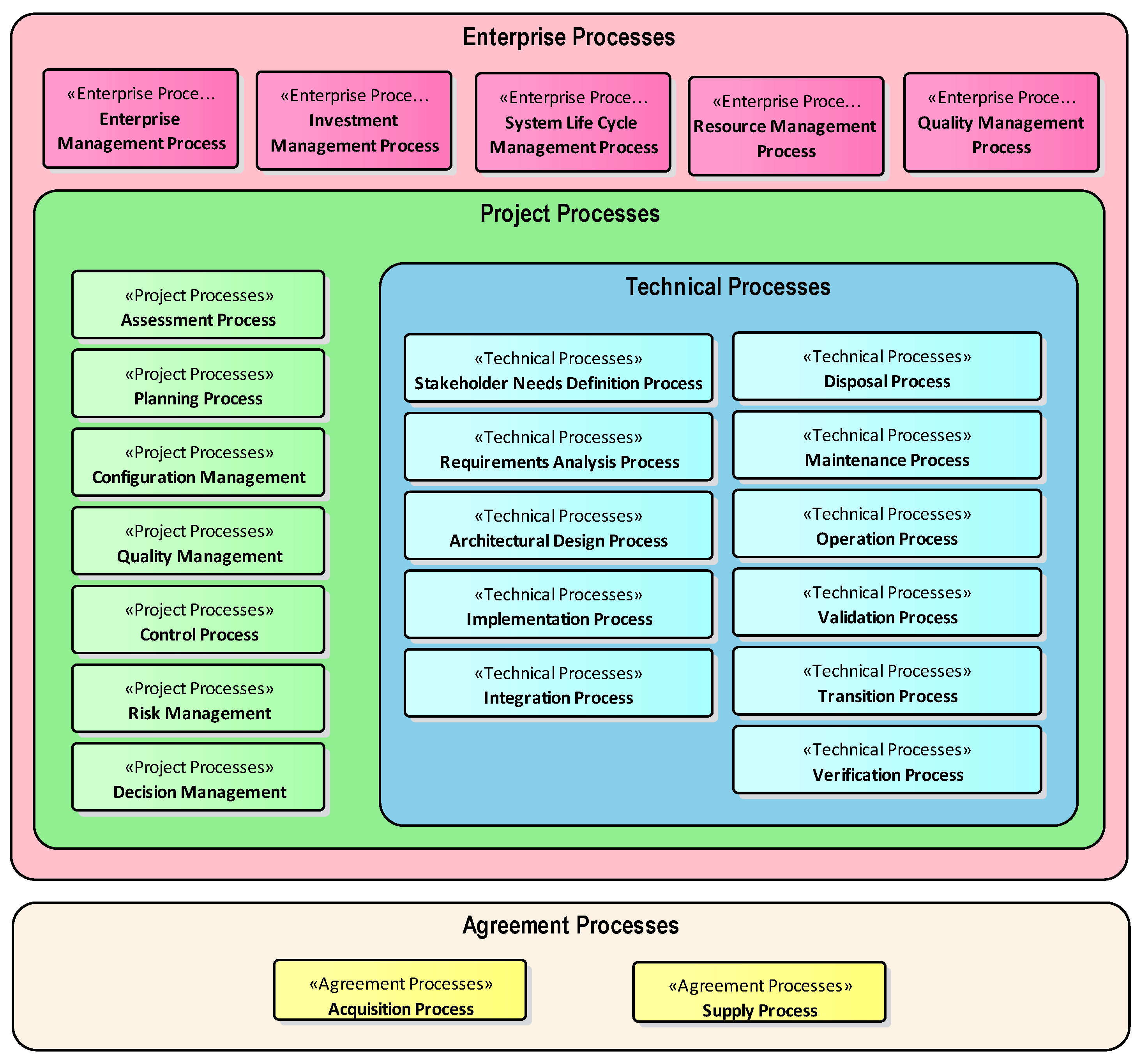
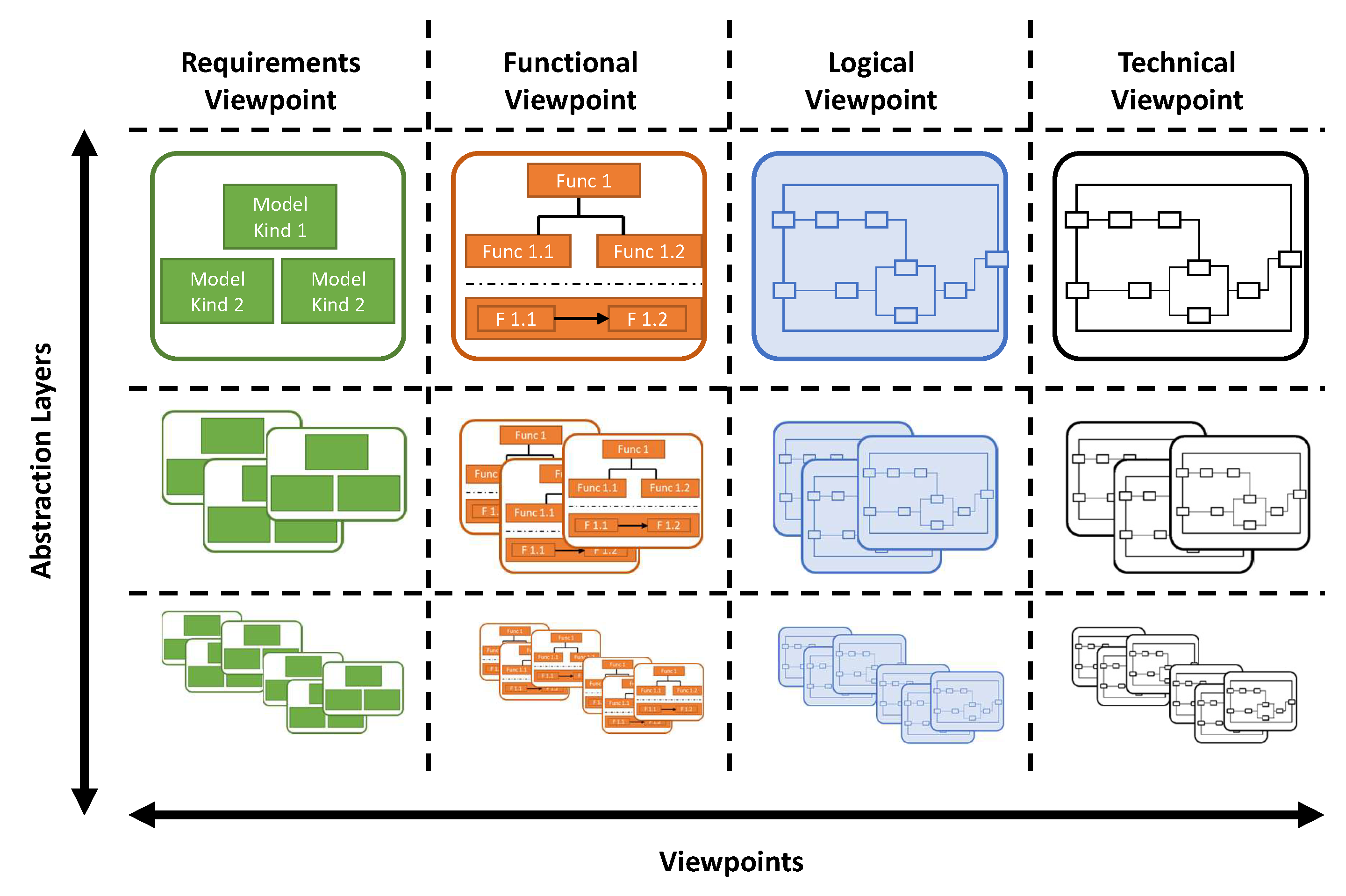
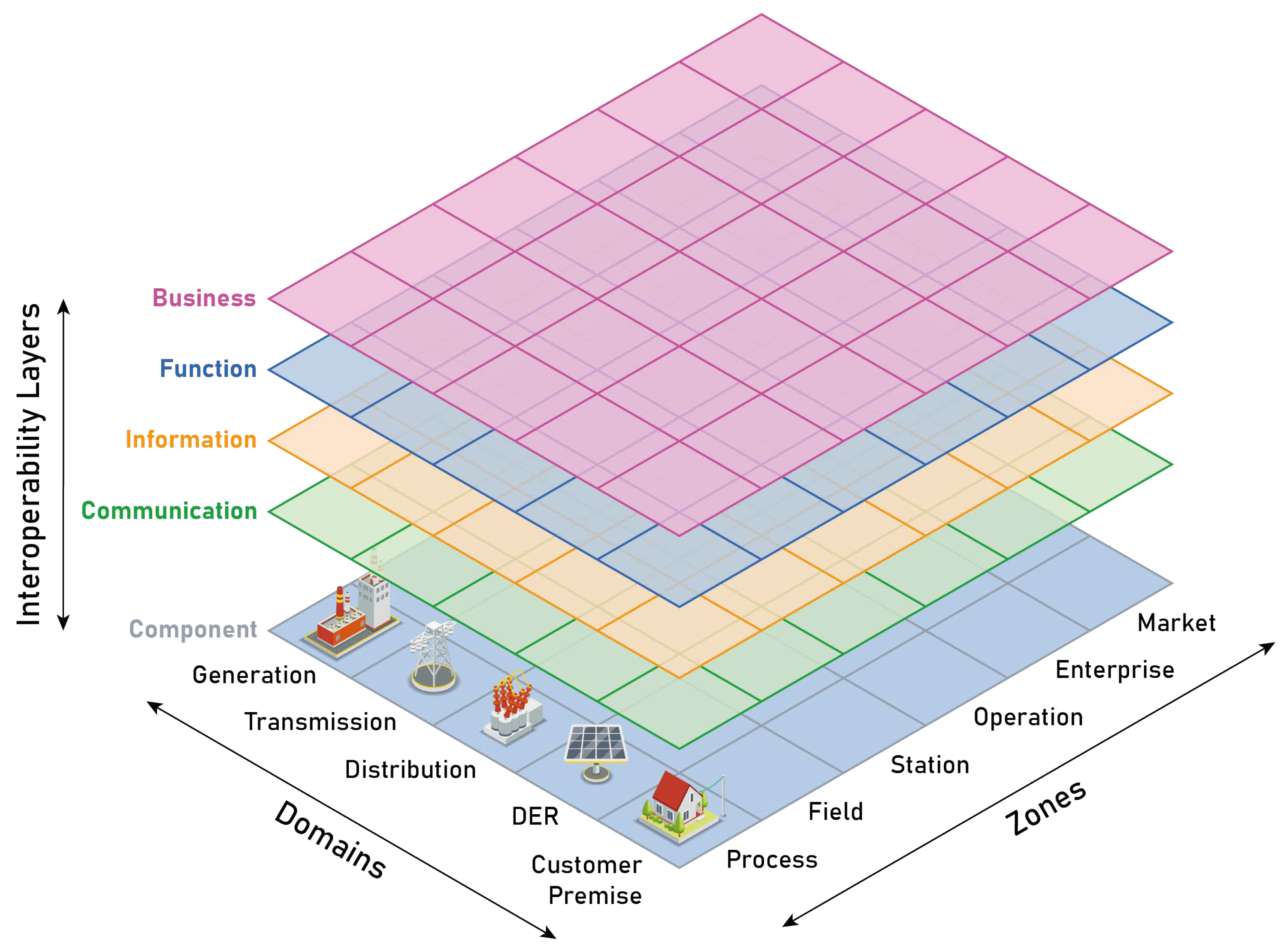
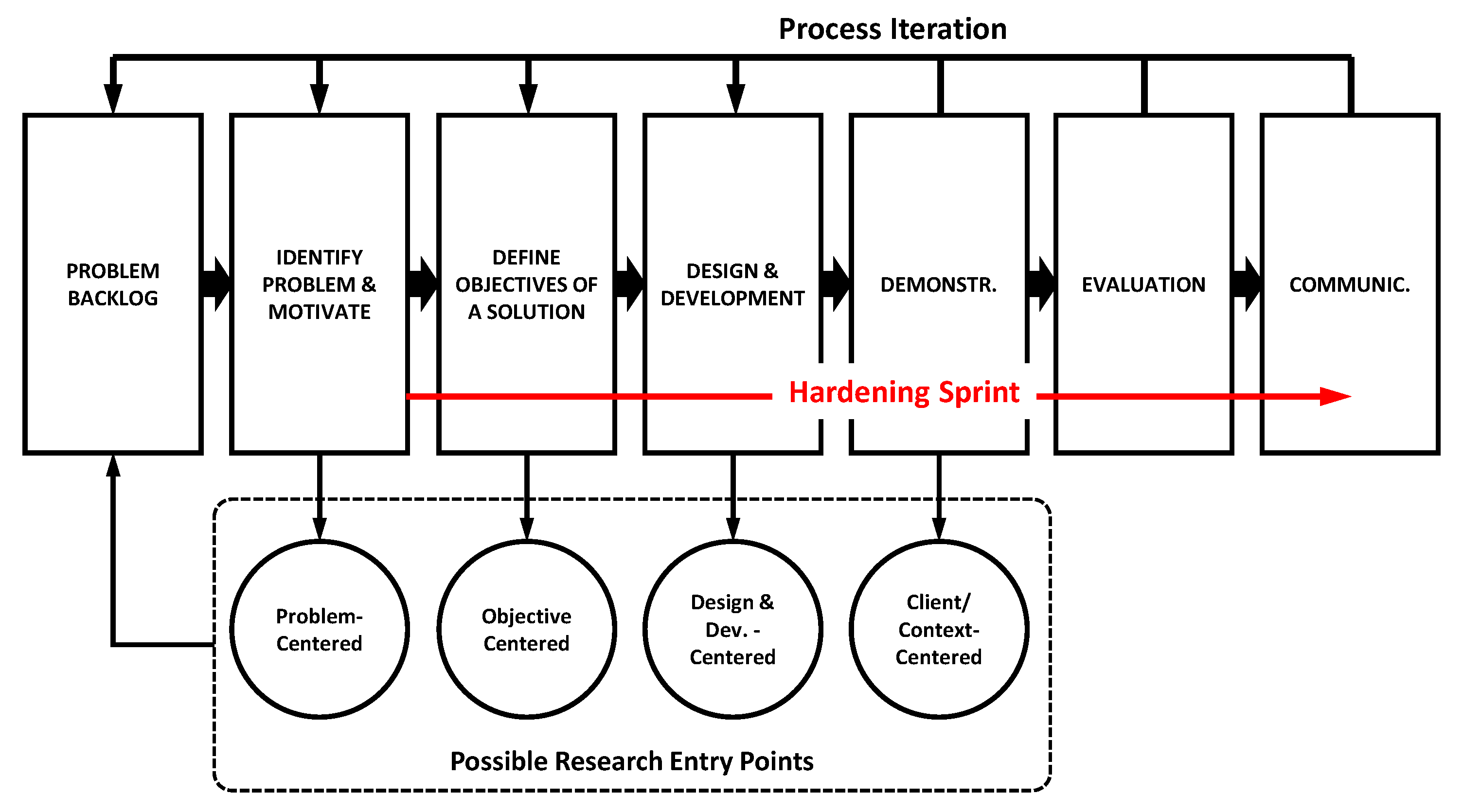
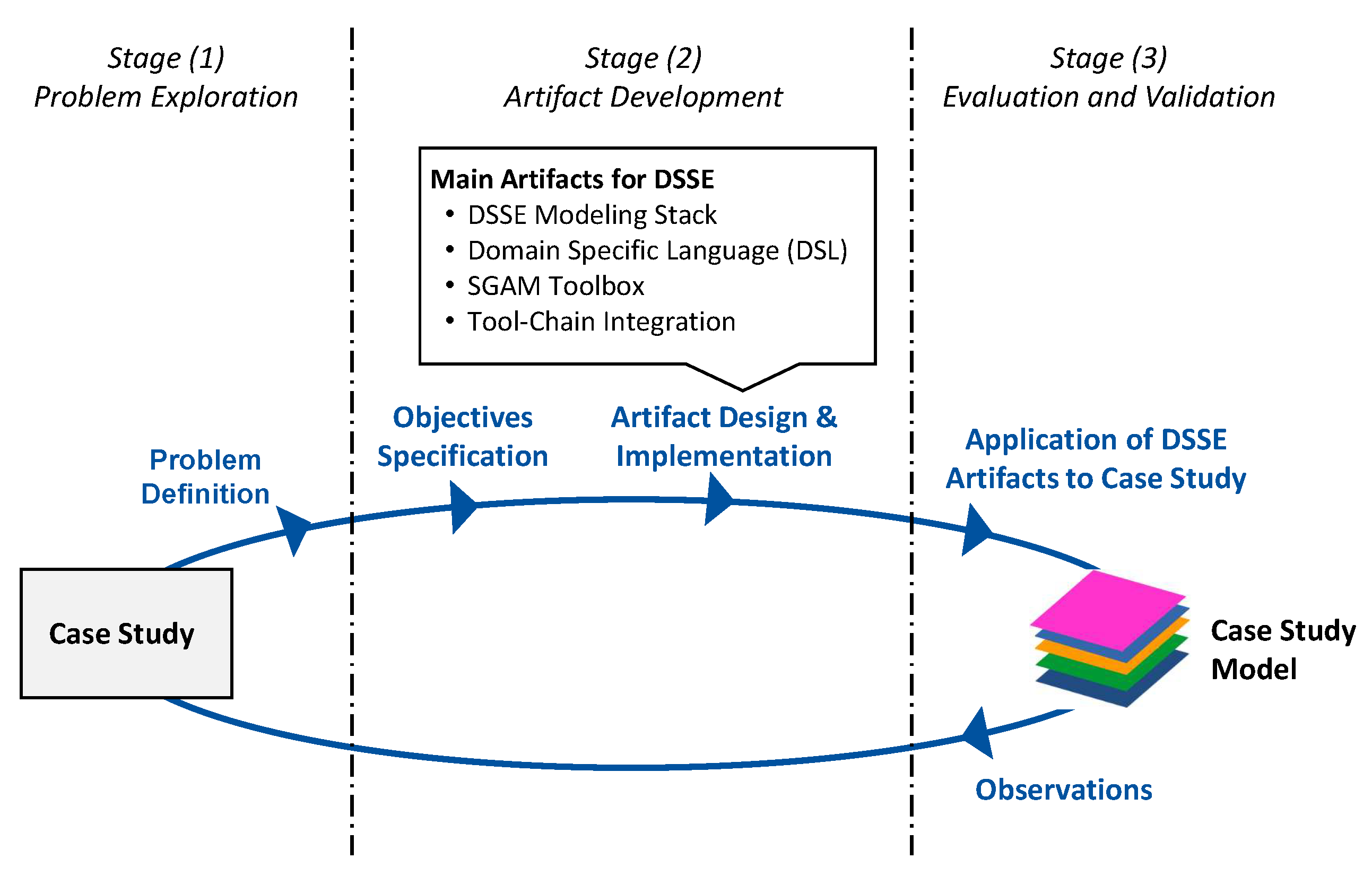
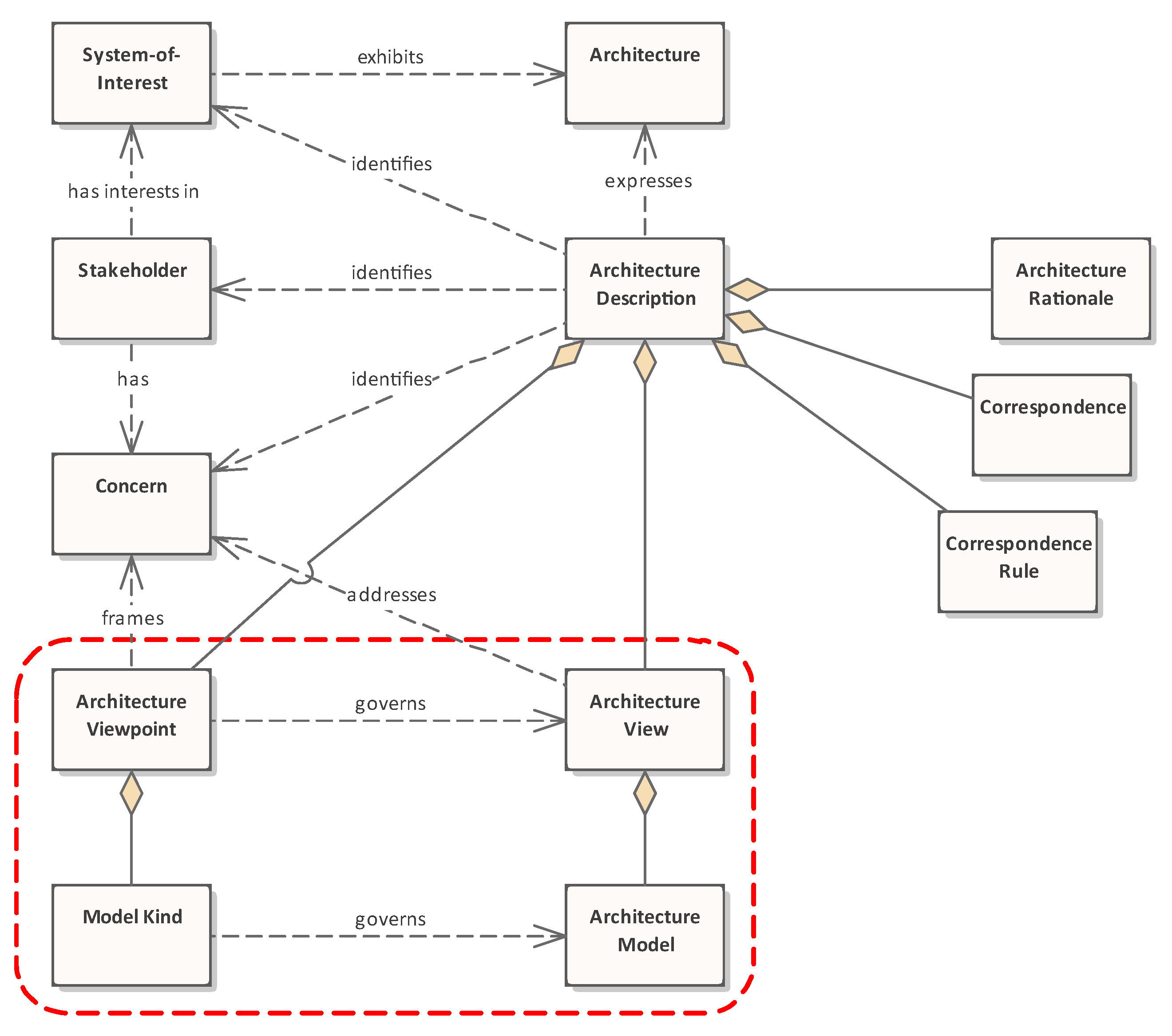
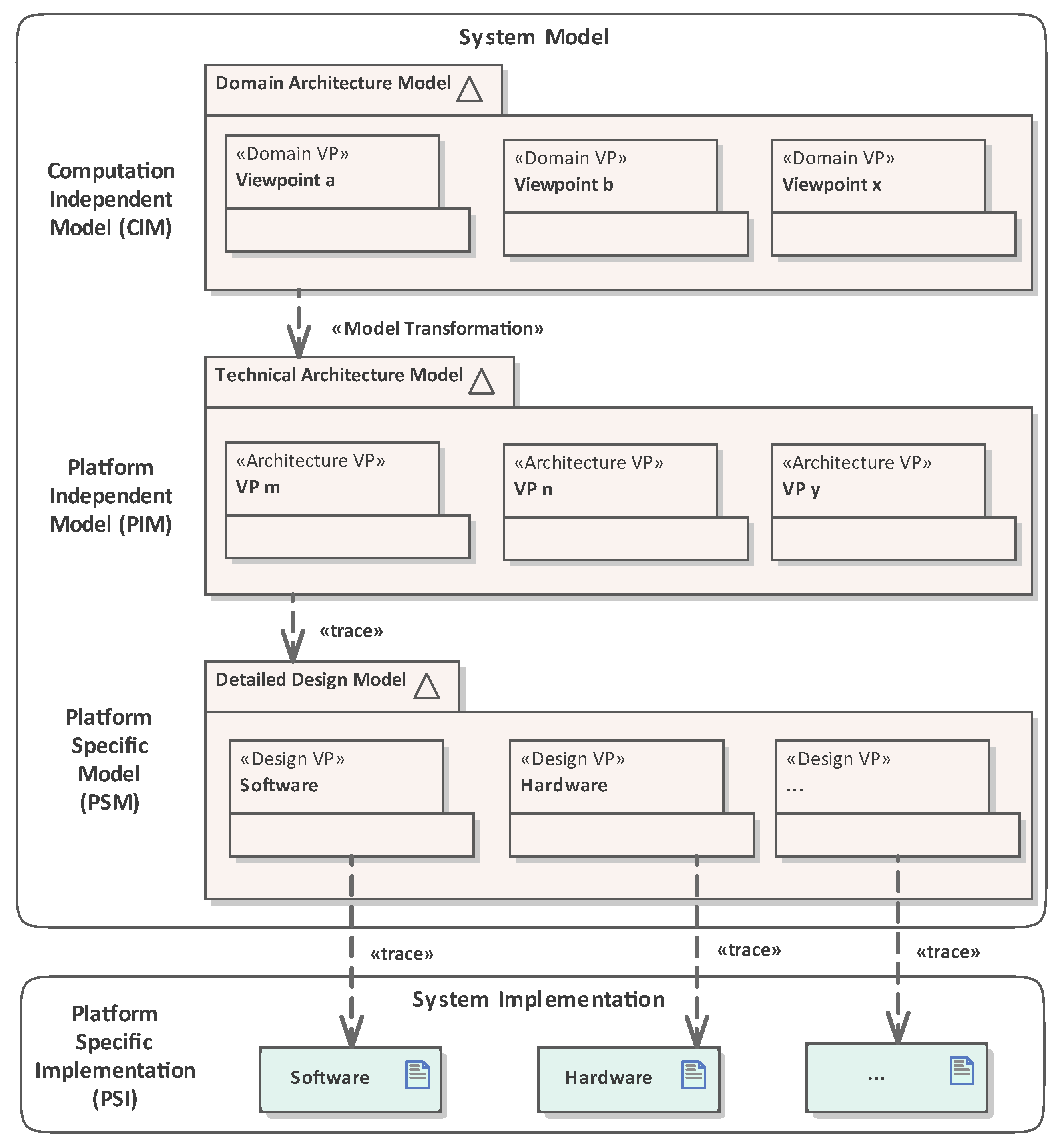
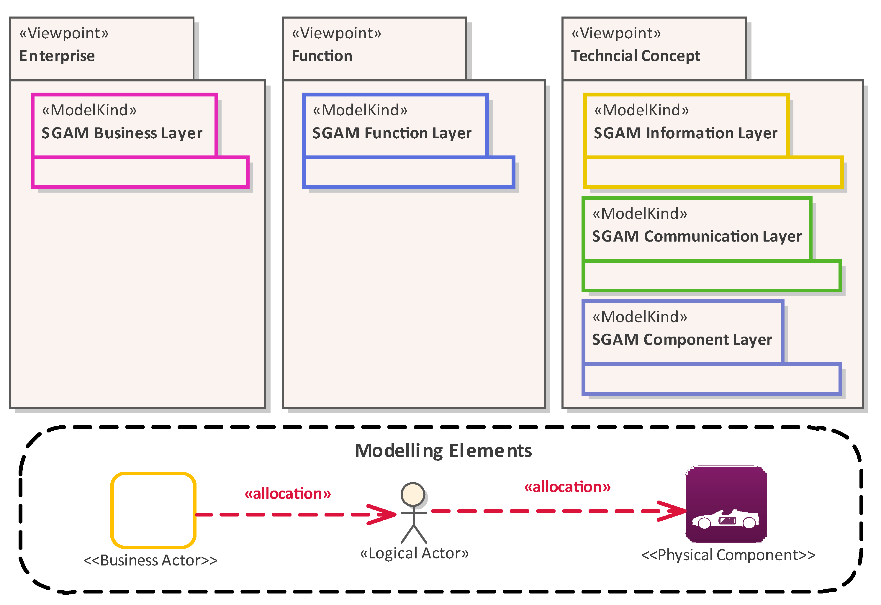
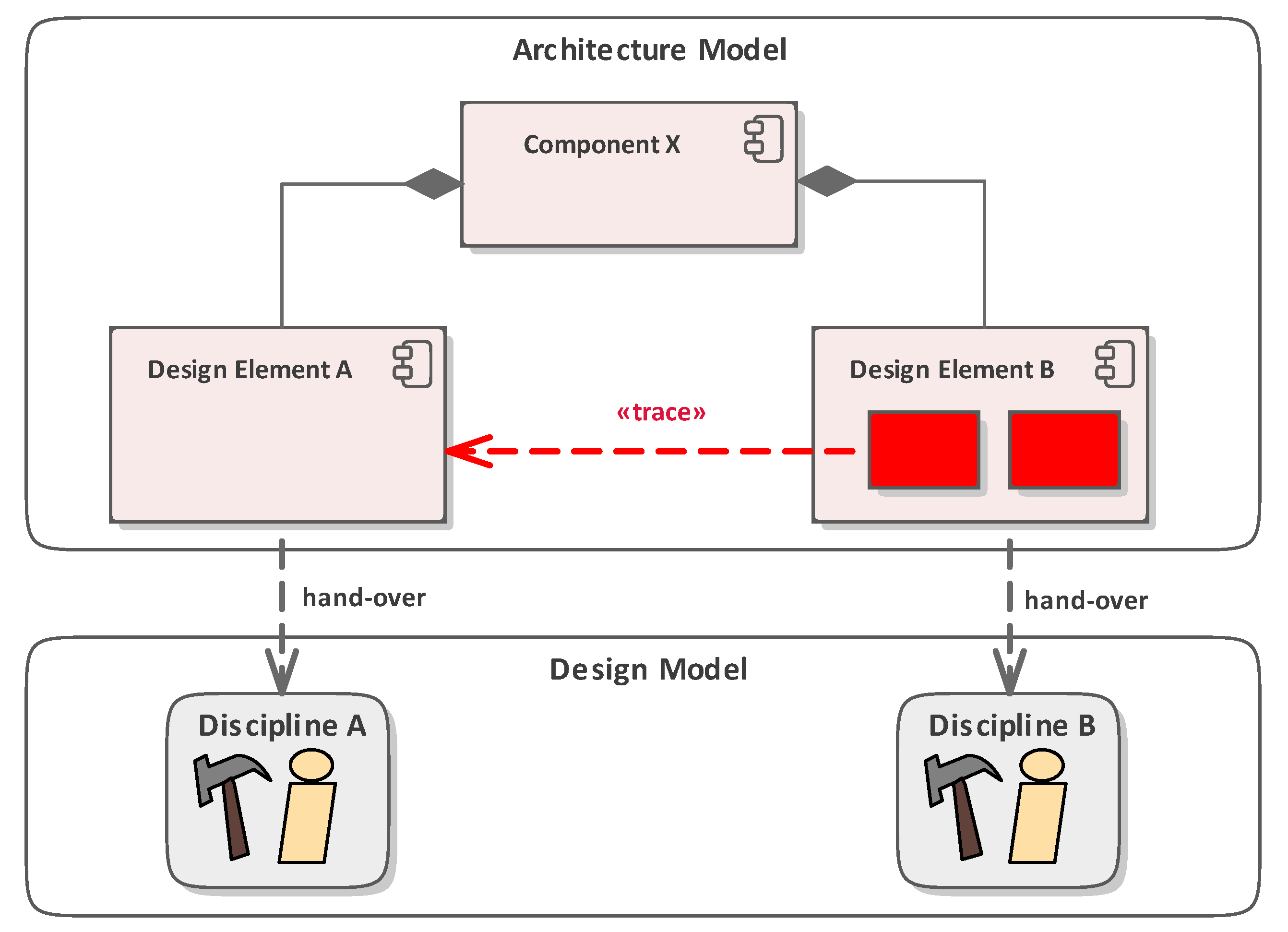
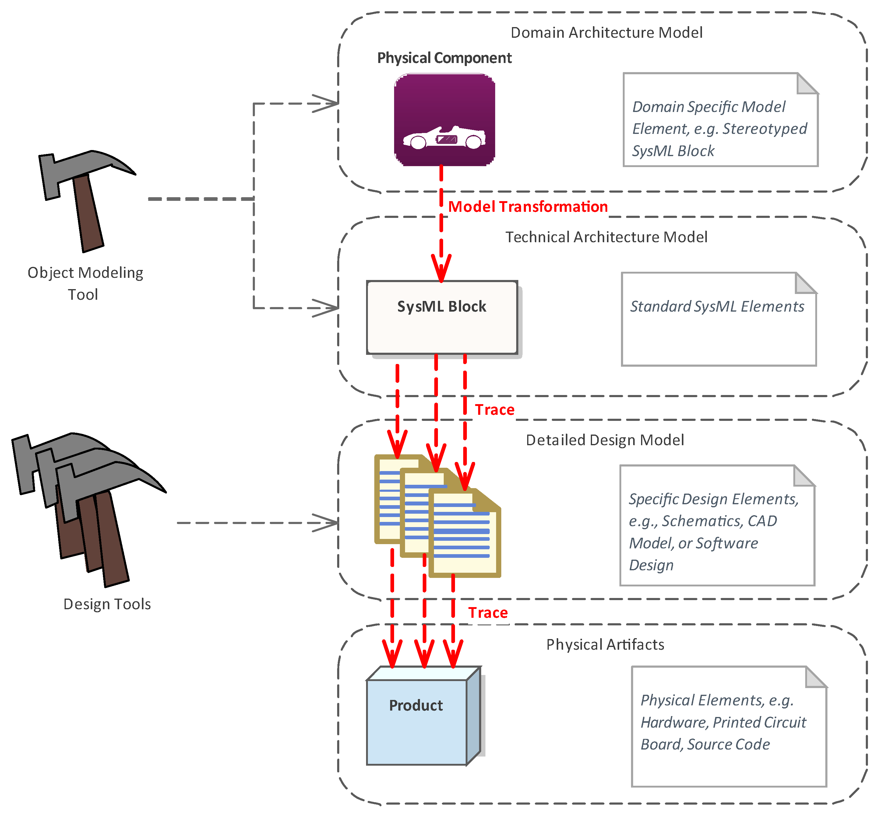
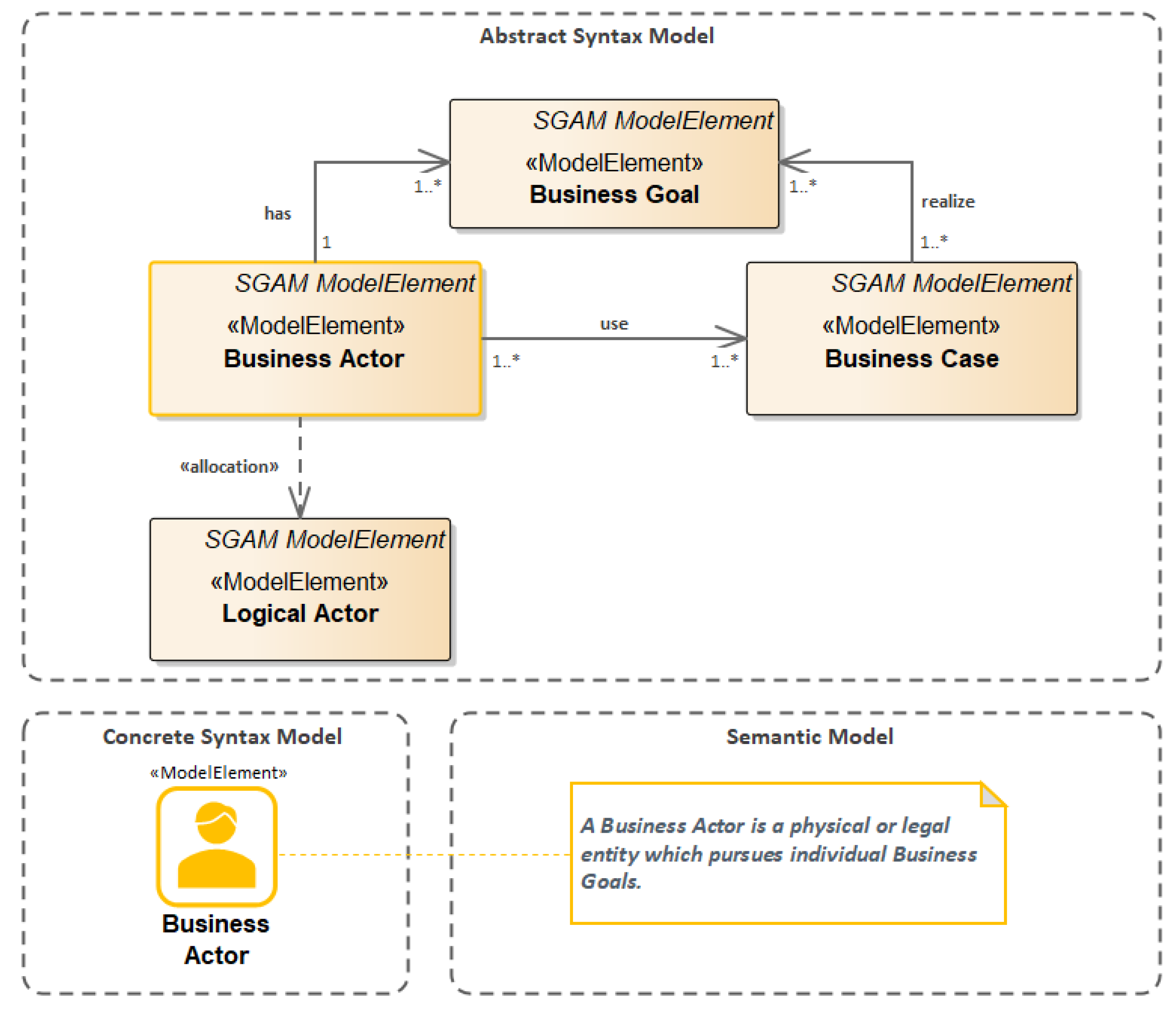
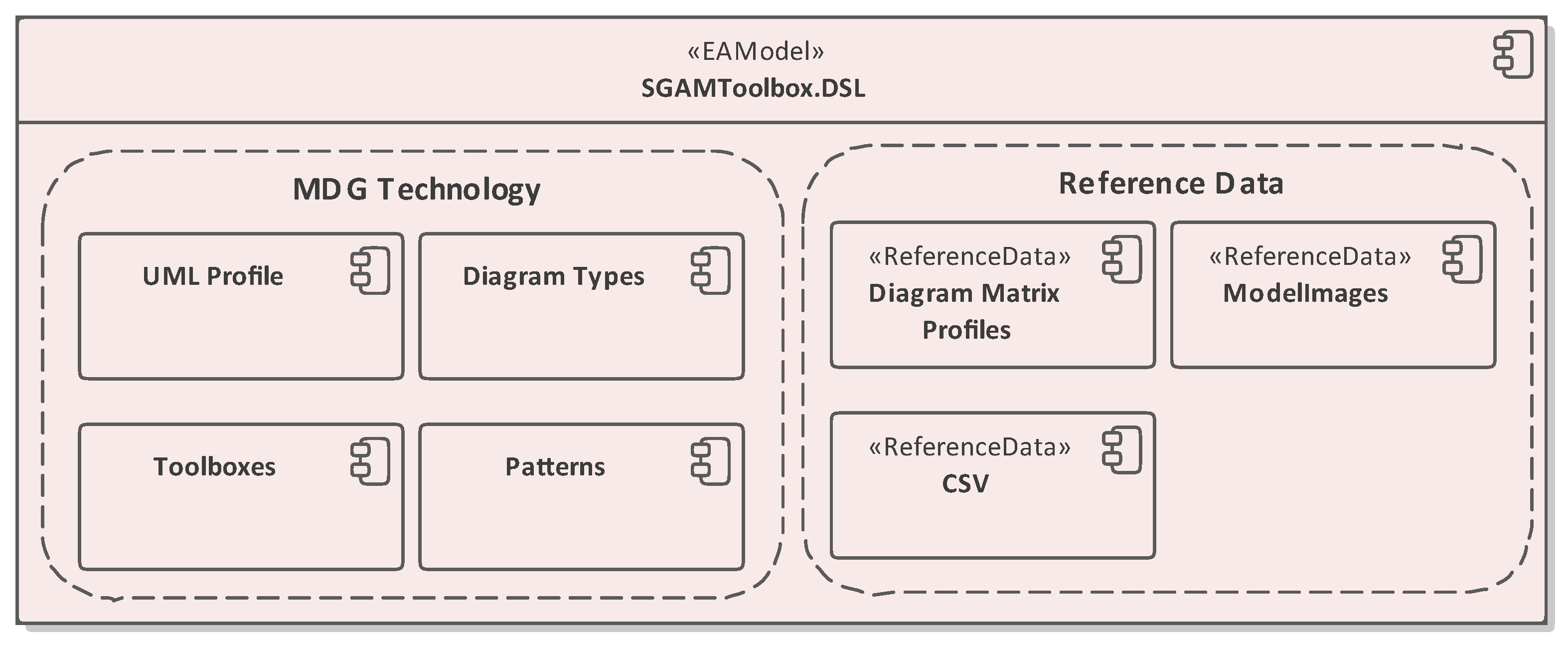
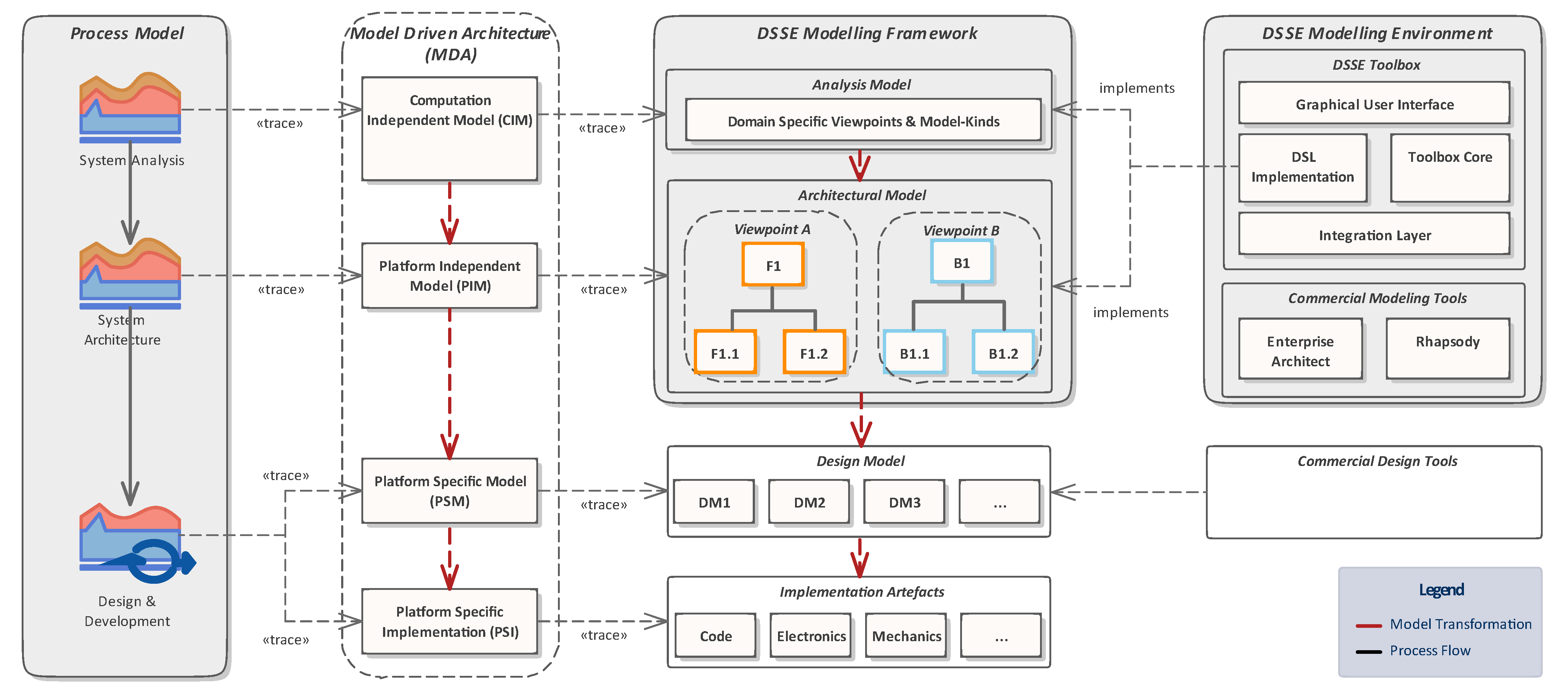
Table 1.
Comparison of different approaches.
| Approach | Scope and Focus |
|---|---|
| Object Modeling |
|
| Domain Specific Architecture Frameworks |
|
| Domain Specific Systems Engineering |
|
Publisher’s Note: MDPI stays neutral with regard to jurisdictional claims in published maps and institutional affiliations. |
© 2022 by the authors. Licensee MDPI, Basel, Switzerland. This article is an open access article distributed under the terms and conditions of the Creative Commons Attribution (CC BY) license (https://creativecommons.org/licenses/by/4.0/).
Share and Cite
MDPI and ACS Style
Neureiter, C.; Binder, C. A Domain-Specific, Model Based Systems Engineering Approach for Cyber-Physical Systems. Systems 2022, 10, 42. https://0-doi-org.brum.beds.ac.uk/10.3390/systems10020042
AMA Style
Neureiter C, Binder C. A Domain-Specific, Model Based Systems Engineering Approach for Cyber-Physical Systems. Systems. 2022; 10(2):42. https://0-doi-org.brum.beds.ac.uk/10.3390/systems10020042
Chicago/Turabian StyleNeureiter, Christian, and Christoph Binder. 2022. "A Domain-Specific, Model Based Systems Engineering Approach for Cyber-Physical Systems" Systems 10, no. 2: 42. https://0-doi-org.brum.beds.ac.uk/10.3390/systems10020042
Note that from the first issue of 2016, this journal uses article numbers instead of page numbers. See further details here.