Constructing True Model-Based Requirements in SysML


Virginia Tech, Blacksburg, VA 24061, USA
*
Author to whom correspondence should be addressed.
Systems 2019, 7(2), 19; https://0-doi-org.brum.beds.ac.uk/10.3390/systems7020019
Submission received: 5 February 2019
/
Revised: 11 March 2019
/
Accepted: 26 March 2019
/
Published: 28 March 2019
(This article belongs to the Special Issue Model-Based Systems Engineering)
Abstract
:Some authors suggest that transitioning requirements engineering from the traditional statements in natural language with shall clauses to model-based requirements within a Model-Based Systems Engineering (MBSE) environment could improve communication, requirements traceability, and system decomposition, among others. Requirement elements in the Systems Modeling Language (SysML) fail to fulfill this objective, as they are really a textual requirement in natural language as a model element. Current efforts to directly leverage behavioral and structural models of the system lack an overarching theoretical framework with which to assess the adequacy of how those models are used to capture requirements. This paper presents an approach to construct true model-based requirements in SysML. The presented approach leverages some of SysML’s behavioral and structural models and diagrams, with specific construction rules derived from Wymore’s mathematical framework for MBSE and taxonomies of requirements and interfaces. The central proposition of the approach is that every requirement can be modeled as an input/output transformation. Examples are used to show how attributes traditionally thought of as non-functional requirements can be captured, with higher precision, as functional transformations.
1. Introduction
Problem formulation, traditionally in the form of requirements, is considered by some authors to be the cornerstone of systems engineering [1]. The development of Model-Based Systems Engineering (MBSE) has led to the idea of substituting traditional shall statements by models [2,3,4,5,6,7]. This transformation is expected to provide several benefits, including enhanced mapping, traceability, and system decomposition [6]. Furthermore, incorporating models of requirements within a central model of the system, instead of leveraging textual statements in natural language, could “facilitate requirement understanding and foster automatic analysis technique” [5]. This need demands exploring the question of what forms a good model of a requirement or a model-based requirement. This is the central point of this paper.
In the Systems Modeling Language (SysML), modeling requirements has primarily taken two paths. In the first path, SysML incorporates elements called requirement element and requirements diagram [8]. These are intended to model the requirements the system is expected to fulfill. In the second path, behavioral models of the system of interest are used (or marked) as requirements. That is, the diagram itself becomes the requirement, without the need for a statement in natural language containing a shall clause [6,7,9]. The first path fails to fulfill its objectives, because the resulting requirement elements are no more than an encapsulation of a textual requirement in natural language as a model element. The second path is promising because it directly leverages behavioral and structural models of the system without requiring statements in natural language. However, we contend that direct use of diagrams or models of the system as requirements may yield two risks. First, by modeling the desired system and not the desired solution space, the solution space may be overconstrained unnecessarily [10]. Second, arbitrarily using a set of models, without an underlying theoretical framework that aids understanding as to how they shape the solution space, may yield coverage gaps in the requirements.
In this paper, we present an approach to construct true model-based requirements in SysML. We leverage some of SysML’s behavioral and structural models and diagrams, with specific construction rules derived from Wymore’s mathematical framework for MBSE [11], a system-centric taxonomy of requirements [12], and a widely adopted taxonomy of interfaces [13]. Wymore’s framework provides the necessary theoretical bases to justify model selection to capture requirements. The requirements and interfaces taxonomies provide context for justifying completeness of requirement diversity in the resulting models [14].
2. Background
The majority of the literature in model-based requirements deals with aspects related to requirements management. Some examples include work on requirements traceability and allocation (e.g., [4,15,16,17,18,19,20,21]) and modeling requirements engineering and management processes (e.g., [18,22]). However, as stated in the Introduction, such work does not address epistemological and structural aspects of model-based requirements. Therefore, this section is limited to prior literature specifically addressing defining and developing model-based requirements.
A common approach for modeling non-functional requirements is to capture them as properties or attributes of the system (e.g., [23,24]). In particular for SysML, this becomes handy because the approach is easily implementable by defining values for the physical block that represents the system of interest [5,22]. However, this approach presents two weaknesses. The major one relates to the ambiguous interpretation of what a non-functional requirement is [12]. We show below that a distinction between functional and non-functional requirements does not really exist. As a result, modeling requirements in this way can yield severe inaccuracies in capturing the real requirement. The second weakness, while minor, is of conceptual nature. Requirements should define the external boundaries of the system, the solution space. Therefore, defining a requirement as a property or attribute of the system is conceptually inconsistent.
A higher level of sophistication in creating model-based requirements can be found in the field of software. Work in this area is aimed at transforming requirements in natural language into models, as part of the requirements elicitation activity. For example, the Model-driven Object-oriented Requirements Editor (MOR Editor) parses a requirement text into a set of properties or constraints associated to objects, called requirement elements [25]. A similar approach is used to interpret user stories [26]. The structure of the requirement models in these cases is derived from a template used to capture user stories in natural language. However, a theoretical framework for the template is not prescribed in these cases. While such approaches provide great flexibility, the resulting model structures acquire the limitations inherent to the template in natural language.
Mathematical definitions alone cannot solve this problem. For example, in the Requirements Driven Design Automation framework (RDDA), a requirement model is defined as
where
- is the set of products described;
- is the set of applications (with );
- is the set of subsystems;
- is the set of features;
- is the set of constraints;
- is the set of constraint numeric descriptors; and
- is the set of relationships on these sets describing the model [27].
This structure enables the automation of certain types of analyses in ways that natural language templates cannot [27]. However, the model itself is internally inconsistent, at least with respect to good practices for requirements engineering and other theoretical developments. For example, subsystems are defined as part of the requirement model. While a relationship between a system requirement and subsystem is meaningful, the requirement should be free of implementation prescriptions [10,28]. Furthermore, as identified above, some elements in the model are not orthogonal. For example, formal definitions are not provided for the terms constraint and feature. This lack of orthogonality may yield inconsistencies in the definition of requirements. We contend that such problems can be overcome by using a requirement model that is grounded on an internally consistent theory. This idea is central to this paper.
In this regard, the notion of semi-lattice has been used to define a requirement. Specifically, a requirement is considered a combination of a condition (e.g., when flying), a carrier (e.g., the system), a property (e.g., power consumption), and a domain (e.g., less than 100 W) [29]. Similar patterns are found in the literature, such as check <condition> after <condition> within <time> [16]. While internally consistent, these definitions present two problems. The first one stems from defining requirements as properties of the system, as discussed above. The second one relates to the way in which conditions may be defined. In particular, the definition does not prescribe against defining any type of system state as a condition. In fact, using states and transitions between states seems to be prevalent as the fundamental model to capture requirements. Using this concept, a functional requirement can be modeled as a required transition from one state to another [30,31,32]. Fundamentally, this leads to modeling a functional requirement as a triplet, such as , where is the current state, is the action triggering the transition, and is the next state following such action [30,31]. Different required properties can then be linked to each one of those states and to the transition trigger. While we believe that the state-based model is valuable for modeling system behavior, we contend that it has a fundamental problem for modeling requirements broadly. Specifically, there is no formalism to define what the system must do in each state, or during the transition. This is critical, since the purpose of defining requirements is to understand the interaction on the system boundaries; as stated above, the requirements define the solution space. In addition, there are multiple interpretations to the meaning of state and transition [33], which accentuates this problem.
A different approach to model-based requirements leverages what the system must do, as opposed to what characteristics it must exhibit or in what states it must transition. This conceptualization is also central to this paper. Prior work has attempted to model requirements as data exchanges and semantics associated with those exchanges [34]. However, the authors claimed that their approach was not broadly generalizable and that it had to be complemented with textual-based requirements [34]. Other authors suggested that requirements may be broadly defined as actions that the system must execute, specifically The [Actor] shall [Action] [Object of Action] [to] [Recipient Actor] [35]. This template was used as the basis to extract textual-based requirements from existing SysML diagrams, specifically from activity diagrams, state machine diagrams, and block diagrams. As such, formal model-based requirements were not defined, but standard SysML directly used as requirements. The weaknesses of this approach are discussed above. The textual formalism has some parallels with the theoretical framework that we present in the next section, but with two key differences. First, we contend that defining the recipient actor for a system requirement is unnecessary, or at least should be abstracted. This is because the purpose of requirements is to define the boundaries of the system. Therefore, by definition, other external actors should not be included in the requirement, but their abstracted interaction should. Second, we suggest that all requirements can be modeled by a minimal set of actions and, hence, they can be prescribed.
3. True Model-Based Requirements
3.1. Theoretical Framework
The purpose of defining system requirements is to allow for distinguishing systems that are acceptable from systems that are not. We differentiate in this paper between system requirements and stakeholder needs [10], and address only the former. In this sense, a stakeholder need refers to a desire on an interaction between the system and an external system or actor. A system requirement takes the form of “an objective or criterion [that] a system is expected to fulfill” and could actually fulfill on its own [10]. In essence, system requirements define the conditions that a system needs to meet to enable the desires of the interaction captured in the form of stakeholder needs. For example, a stakeholder need would indicate the desired level of convenience while transporting something from A to B. Derived requirements would indicate the necessary mechanical vibration profiles provided to an abstraction of that something, which would enable such convenience once the system would be put in the operational context.
Wymore’s conceptualization of system is central to the theoretical framework in this paper. We start by considering that any system can be modeled as a transformation of input trajectories into output trajectories [11]. Since a set of requirements yields a solution space (that is, a set of systems that fulfill those requirements) [10], it follows that a solution space can be modeled as a set of transformations of input trajectories into output trajectories. Consequently, the central proposition of our theoretical framework is that every requirement can be modeled as an input/output transformation. In such models, the inputs, outputs, and transformations may be multidimensional.
Prior work in defining taxonomies for requirements supports this proposition. Requirement types can be reduced to four [12,14], which are listed in Table 1.
We show that these four types of requirements can be described as transformations of inputs into outputs:
- Functional requirements inherently describe input/output transformations. Mathematically, a function is necessarily defined as a mapping between a domain and codomain. From a General Systems Theory perspective, engineered systems are necessarily open [36].
- Performance requirements are, as defined, necessary characteristics, properties, or attributes associated with the inputs and outputs of the transformations that the system shall perform. In fact, this condition is necessary because any attribute transparent to the interaction between the system and external systems should not be considered a requirement due to unnecessarily constraining the solution space [10,28].
- Resource requirements define limits on resources that the system may consume. It is obvious that a resource must therefore be inputted to the system and that it is consumed for producing something. Hence, any limitation imposed on resource consumption is in fact part of a functional exchange and can be modeled in such a way.
- An environment for the system is an abstraction of boundaries between the system and external systems. The environment provides certain conditions under which the system must operate and imposes certain limitations on how the system may affect the environment. In other words, the environment provides certain inputs under which the system must operate and imposes certain limitations on the outputs the system may yield to the environment.
The feasibility of this idea in practice is further supported by Kossiakoff’s taxonomy for external interfaces. According to the author, systems operate in three types of media, namely information, material, and energy, which become inputs to and/or outputs from the system [13]. Hence, it is recognized that transformations are not limited to the logical domain (information), but can be performed on material and energy as well.
Finally, the requirement, as a required input/output transformation, is completed by a required interface through which the system can accept the necessary inputs and provide the desired outputs.
3.2. Basic Model of a Requirement
The basic model of a requirement consists of a logical component and a physical component. The logical component describes the required transformation. The physical component describes the interface(s) through which the transformation occurs. We use (and extend) SysML’s Sequence Diagram to capture the logical component; SysML’s Internal Block Diagram is used to capture the physical.
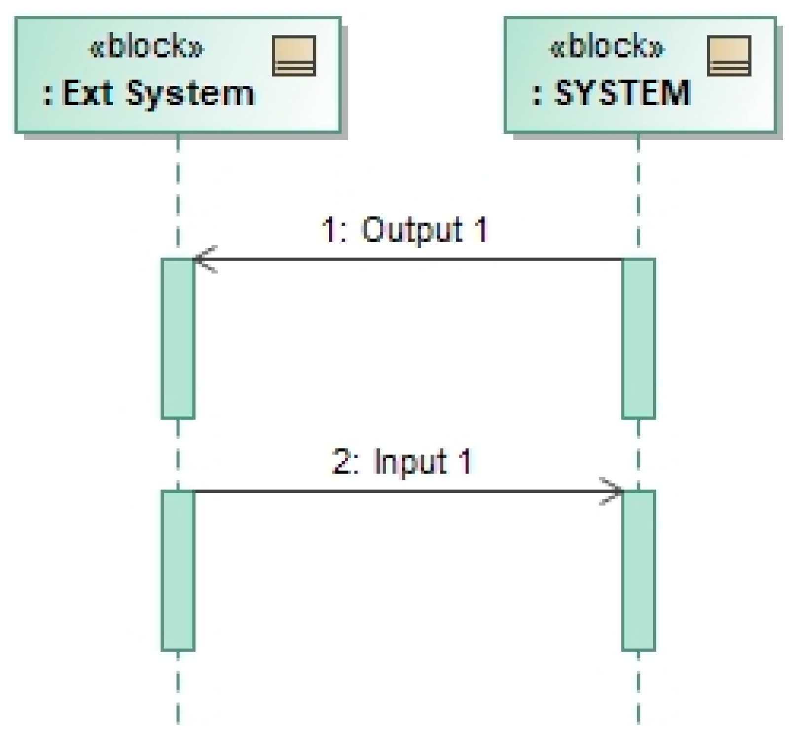
The Sequence Diagram was chosen over other SysML model structures because it provides the necessary elements to model inputs and outputs without prescribing any internal behavior of the system. As shown in Figure 1, the basic Sequence Diagram consists of input signals, output signals, and system boundaries. System boundaries are represented by the line that models the system (called lifeline). This visualization forces the modeler to consider only the boundaries of the system (as opposed, for example, to using an activity diagram). We chose to use Signals in SysML notation to model the inputs and outputs of the system. The definition of signal allows for capturing all logical properties of required system inputs and outputs. In this way, the required transformation is captured as a property of the output signal, since it is defined as a function of system inputs. In addition, using signals allows for capturing specific types of messages, even though they may have the same logical meaning.
Certainly, the Sequence Diagram is already part of SysML. Its use for modeling requirements demands two new aspects that are presented in this paper. The first one is related to intent. Specifically, the model does not capture the expected behavior of a system, but its required behavior. Therefore, the difference between a Sequence Diagram that captures the behavior of a system and one that captures its required behavior will not necessarily differ in their level of abstraction or accuracy of values. However, they are different in nature; the former is an abstraction of a system and the latter is an abstraction of a solution space. This difference in intention, although subtle, is captured through the values associated with the different elements of the model. This aspect will become more apparent in the next section.
The second new aspect is how signals are treated. Traditionally in SysML, a signal in a sequence diagram represents a logical message. We extend that formalism to let a signal represent any type of logical exchange between two systems, as described in Kossiakoff’s taxonomy and described above. In this way, a signal can represent an energy or material exchange, for example. Furthermore, the signal definition is extended to capture not only discrete messages, but also signals of continuous nature. Certainly, such continuity can still be modeled in SysML by using an infinite loop element that repeats at infinitely small periods. However, the extension allows for more efficient modeling. Instead of capturing continuous properties of the signal in the sequence diagram as a property of the overall exchange, they are directly captured in the signal element.
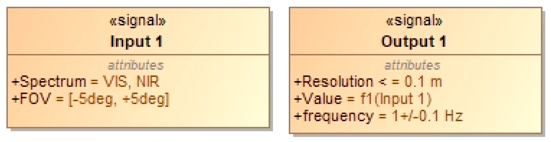
Attributes of the elements signal are used to model the required characteristics of the inputs and outputs. Figure 2 shows an example. Attributes of input signals capture the conditions that the system is required to accept. Attributes of the output signals capture the characteristics that those outputs must exhibit. There is no prescription for how those properties may be defined; they may take the form of value ranges, images, or functions (such as the required transformation that is allocated to output signals). For this purpose, other SysML elements or diagrams may be used, such as a parametric diagram to capture a required transformation. However, it should be noted, as described in the meta-model in Section 3.6, that the key elements that define the requirement are the signals; other modeling elements flow from them.
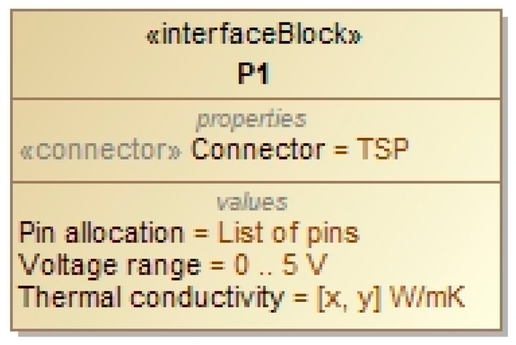
Physical interfaces are modeled as ports of a block representing the system. Using standard SysML practice, signals are then allocated to corresponding connections between ports, as shown in Figure 3. Contrary to most of the practice in MBSE, the requirement for the system is defined at port level, and not at part level. This makes the model consistent with the theoretical framework presented in the previous section: requirements define external transformations, not internal behavior. Ports are defined by InterfaceBlocks. Properties of these blocks capture requirements associated with the physical interface, as shown in Figure 4. As was the case for signals, there is no prescription for how those properties may be defined.
In addition, there is no prescription for what attributes and properties need to be defined for signals and ports. This is left open for each project. However, to guarantee consistency with the theoretical framework presented in the previous section, the following rules apply:
- Properties that are related to the meaning of the exchange (e.g., packet configuration of a message, performance of a signal, etc.) must be modeled in the logical domain (i.e., signals). As previously stated, one such property is the transformation function, which is allocated to output signals.
- Properties that are related to the specific vehicle through which meaning is conveyed (e.g., electrical properties of a signal through which a message is sent) must be modeled in the physical domain (i.e., ports). These properties include aspects related to transport layer (such as data structure) and physical layer (such as voltage levels).
3.3. Adding Richness to the Requirement Model
Certain requirements may impose or define logical and time dependencies between inputs and outputs. In textual form, these may take forms such as The system shall do C once conditions A and B are fulfilled or The system shall do B in less than X s after having done A. The formal specification of SysML’s Sequence Diagram provides modeling features that can enhanced the richness of the requirement model by capturing these dependencies. It is also noted in this case that such formalisms are used as models of the requirements (that is, of a solution space) and not as a model of the actual behavior of a system.
Conditional dependencies are captured using interaction operators. Note that these model elements become part of the requirement model as well. For example:
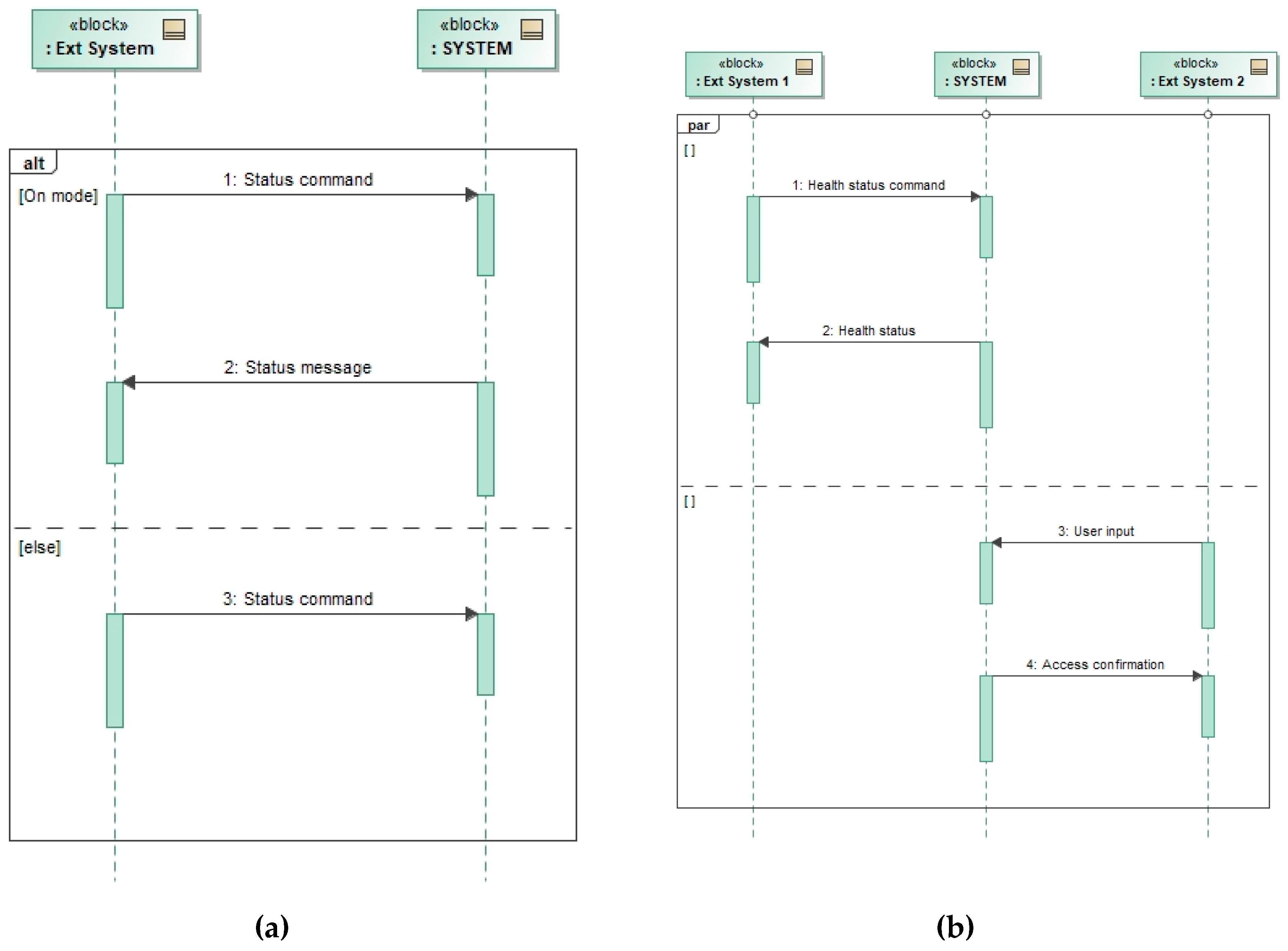
- Alternative behavior: This interaction operator can be used to capture a requirement to the system to exhibit different behaviors depending on certain conditions. No limitations are imposed in the conditions. They may refer to operational modes, historical actions, or external conditions (e.g., outside temperature). Figure 5a shows an example of a requirement model, where the system is required to react to external commands only if it is in On mode; if in Off mode, the system is required to accept the command but to not react to it (which is a different requirement from stating that the system will not receive commands when in Off mode).
- Parallel behavior: This interaction operator can be used to capture a requirement to perform two or more transformations in parallel. No limitations are imposed on the type of elements that need to be executed in parallel. For example, they may refer to completely independent transformations that are performed in parallel, to the provision of several outputs simultaneously, or to the reception of inputs simultaneously. Figure 5b shows an example of a requirement model, where the system must perform a background health monitoring exchange while also responding to other operational requests.
- Loop: This interaction operator can be used to capture a requirement to execute a transformation repeatedly until a condition is met.
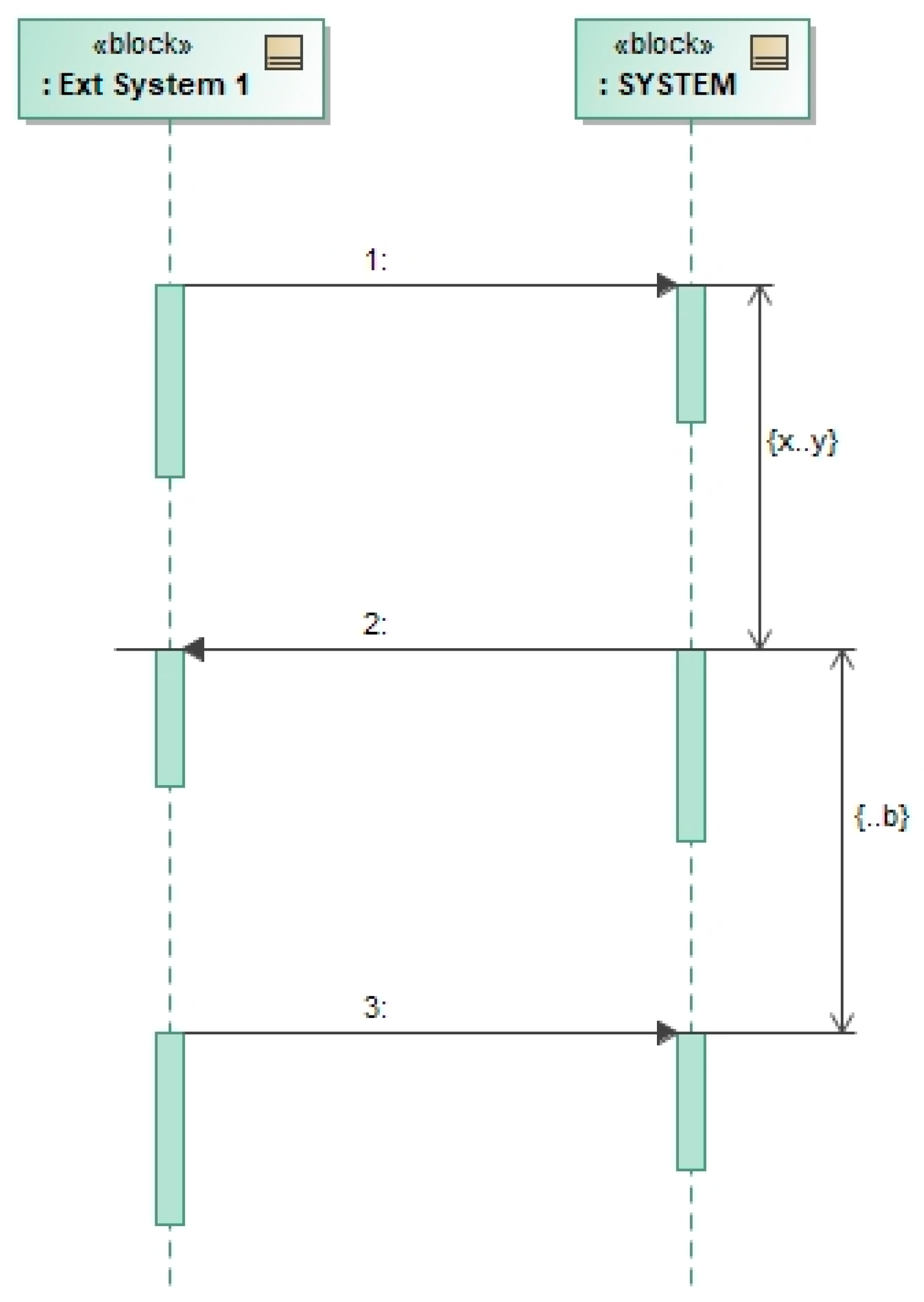
It should be noted that the example models in Figure 5 may be (and likely are) incomplete. For example, restrictions on time dependencies between inputs and outputs are not defined. From a problem formulation standpoint, Figure 5a would imply that as long as the system would provide the Status message output after receiving the Status command, the system would be acceptable, regardless of the time that it would take it to do so. If this would not be the case (and it is generally not the case), requirements on time dependencies need to be captured in the model. This is done by adding duration constraints between the different inputs and outputs, as shown in Figure 6. It should be noted that requirements on timing dependencies are not limited to time lapses between inputs and outputs. They may also impose time constraints between outputs and define timing relationships between inputs. As a reminder, these duration constraints do not define the expected behavior of the system in this case, but instead its desired behavior.
3.4. Modeling Simultaneity of Requirements Applicability
Given a set of requirements, different subsets may need to be fulfilled simultaneously. Simultaneity can be modeled using interaction objects, as described in the previous section. In fact, it is possible to depict the model of an entire set of requirements in a single sequence diagram. However, such an approach would not be convenient due to the resulting modeling and interpretation complexities. We extend SysML’s state machine diagram for capturing simultaneity of requirements applicability.
State machine diagrams have been widely used to capture patterns of how a system behaves against certain sequences of input trajectories [11]. Using states allows for simplifying an otherwise infinite model of exchanges, by finding repetitions in the way in which inputs arrive to the system.
We have leveraged this concept to create state-based requirements, or more precisely, mode-based requirements. In essence, we define a mode requirement as a collection of requirements that do not have conflicting requirements and that must be fulfilled simultaneously. Conflicting requirements cannot be fulfilled simultaneously. Therefore, a mode requirement must necessarily be free of them. Otherwise, the mode requirement would likely lead to an empty solution space [10]. Simultaneity is also necessary, since it captures the notion that the system needs to fulfill several requirements at the same time. Furthermore, we define that two mode requirements are distinct if and only if their collections of requirements are not identical. Using traditional jargon, this could be understood as modeling operational scenarios in which certain conditions apply simultaneously.
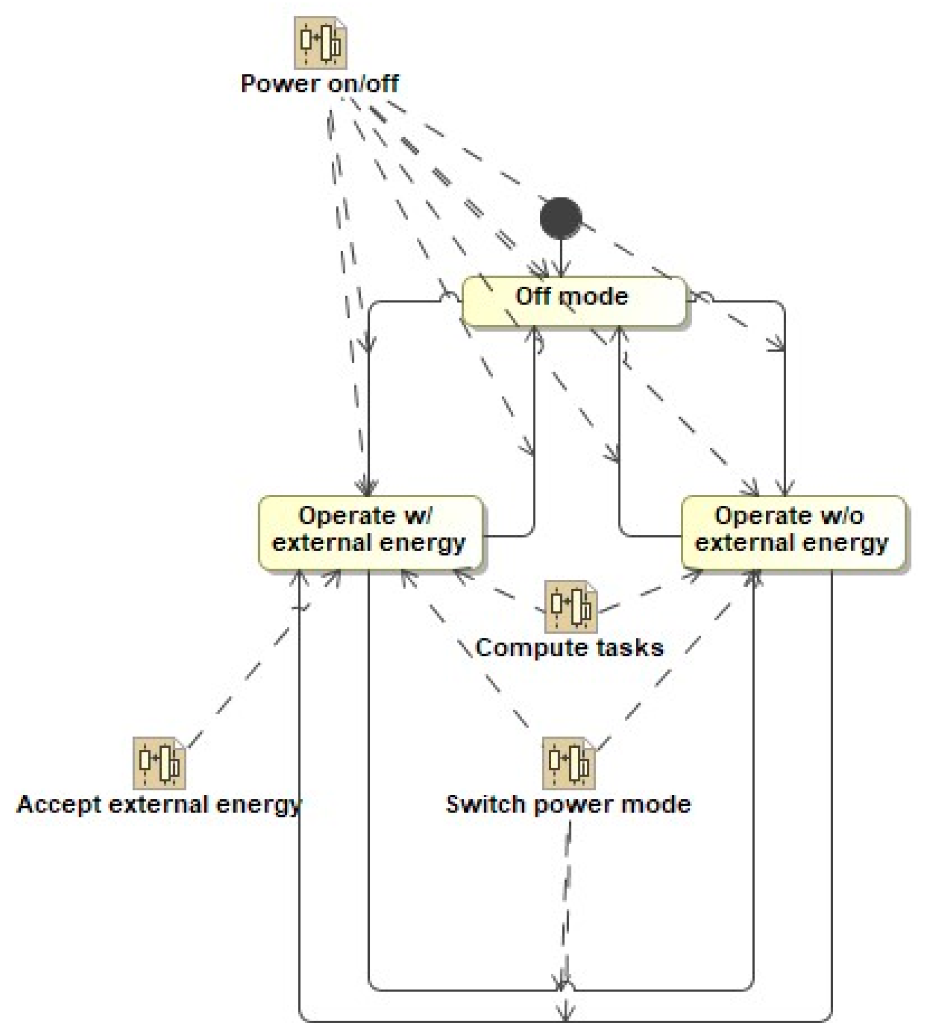
Specifically, the state machine diagram in SysML is extended to capture mode requirements as follows (cf. Figure 7). Each state element captures a mode. Each requirement (that is, the model of each requirement) that is applicable in that mode is linked to the corresponding state element. Note that, since the functional aspects of the requirement model are linked to its physical aspects, it is sufficient to link the Sequence Diagram to the state element. A final model element is needed to capture how each subset of the requirements becomes applicable. This is captured by one or more sequence diagrams, which model the required conditions for transitioning between mode requirements. These sequence diagrams link then to the states for which the transition occurs, as well as to the transition itself.
3.5. Non-Functional Requirements are Always Related to Functional Requirements
Considering that every requirement can be modeled as an input/output transformation makes distinguishing between functional and non-functional requirements unnecessary. This is a departure from most literature in requirements engineering. Its merit is justified in Section 3.1. We show in this section three specific instantiations of how traditional non-functional requirements can be better described as transformations.
The key paradigm change is to recognize that functional transformations are not limited only to operational or commandability aspects of a system’s behavior. Instead, they also exist in physical interactions of the system with other external systems. Consider for example the requirements for a locking system on a door. With the traditional conceptualization, one would come up with requirements associated with the operation of the locking mechanism, as depicted in Figure 8a. Those requirements would be complemented with a set of non-functional requirements, such as vibration levels that the locking system needs to withstand, derived from the mechanical forces injected into the locking system. With our proposed conceptualization, those mechanical forces are also modeled as inputs to and outputs from the system, as shown in Figure 8b. As can be seen, pushing the door to open it injects a force into the door, which is transmitted as a force to the lock. Vibration levels are hence properties of those input signals to the system, not a property of the environment as an external system.
We contend that those physical properties can eventually be linked to functional transformations, even if not apparent initially. For example, consider a requirement on the maximum mass of a satellite. As discussed above, requirements should be defined on external boundaries of the systems, not as attributes of the system. Where does mass fit then? The first step is to question why there is a mass requirement in the first place. Let us keep it simple and state that the restriction on the satellite mass derives from the need to launch the satellite on a certain rocket. The satellite is attracted by Earth’s gravity, pulling the rocket in an opposing direction from where it needs to go, which puts more energy demands on the rocket to leave the Earth. In fact, if the satellite could be designed so that it would float inside the rocket (that is, it would compensate gravity somehow), there would be no need for a mass requirement. Therefore, in essence, a restriction for the satellite mass exists because the satellite is providing an output to the rocket (force in one direction) at a particular joint between the satellite and the rocket (physical interface). Consequently, the mass requirement can be easily modeled as a property of a required logical output of the system (force) through a physical interface.
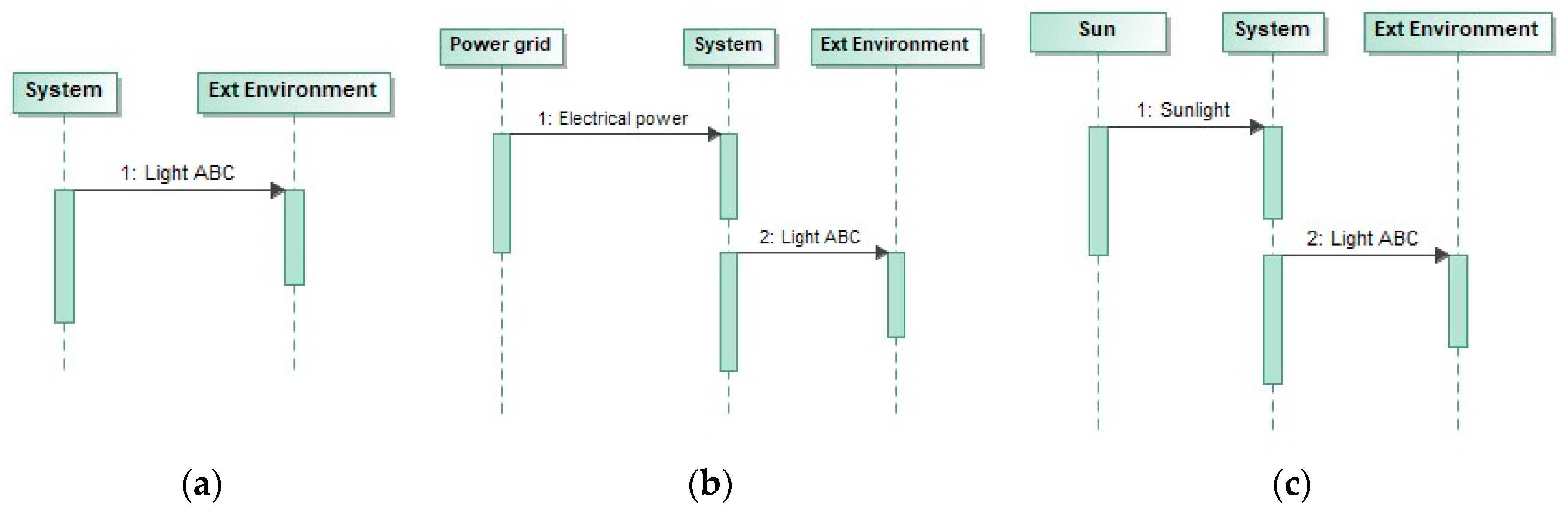
In addition, we have found that capturing non-functional requirements as models increases the level of precision over using natural language. Consider as an example the requirement the system shall exhibit ABC color. The three models in Figure 9 capture such a requirement. However, as can be seen, they describe a different solution space. The model in Figure 9a indicates that the system has to exhibit such a color inherently, without using any external source. The model in Figure 9b indicates that the system has electrical power available for use, when generating the color. The model in Figure 9c indicates that the system can use the sunlight to provide the required color. It should be noted that in the three cases, the apparent non-functional requirement of color can be modeled as a functional exchange (e.g., as in Figure 9c, a paint is no more than a reflection (output) of incoming light (input)). Certainly, all these model-based requirements can also be described in natural language. We contend however that conceptualizing any requirement as a transformation pushes the requirement analyst to be explicit about his/her mental models with the requirement, increasing consistency and completeness.
3.6. Meta-Model
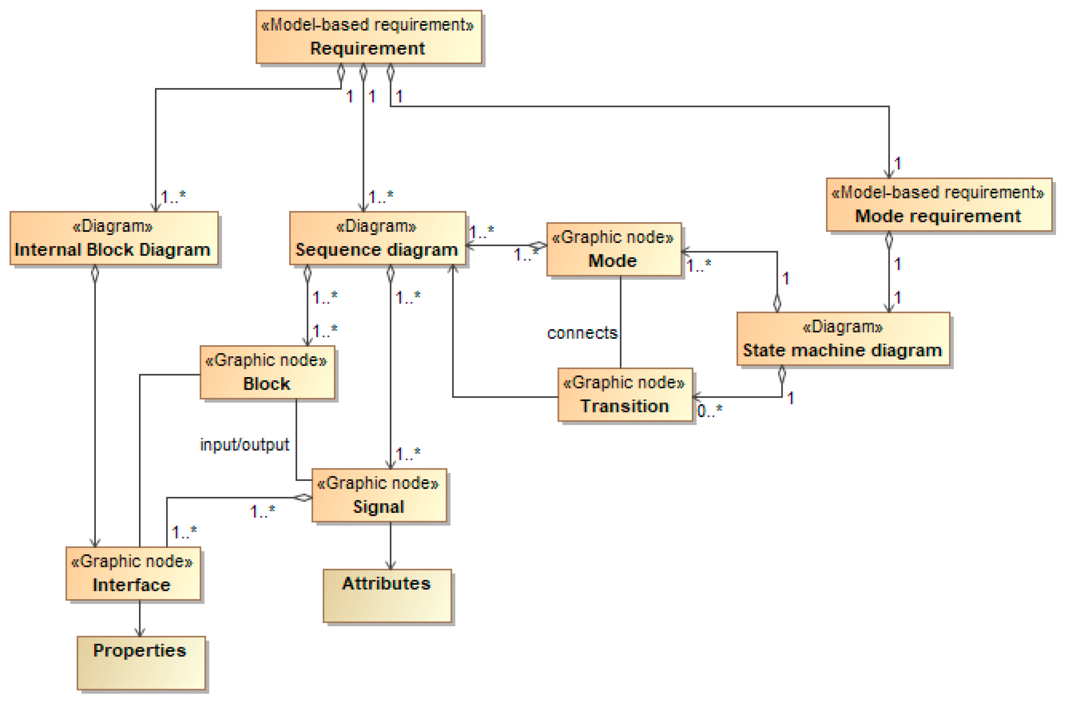
Figure 10 shows a partial meta-model of the model-based requirements framework presented in this paper. Its purpose is to serve as a general guide for the reader. Future work will address formalizing the meta-model. It should be noted that all elements and diagrams in Figure 10 extend the original elements and diagram in SysML, as described in previous sections.
The meta-model in Figure 10 explains how the different elements that form a model-based requirement relate to each other. These relationships are fundamental to guarantee that the definition of the model-based requirement is complete. Two aspects are worth noting in the meta-model. First, the meta-model shows that the model-based requirement is formed by three main pillars, as previously discussed: a sequence diagram (which captures the input/output exchanges), an internal block diagram (which captures the physical interfaces through which the inputs and outputs are conveyed by the system to external actors), and mode requirements (which describe the sets of requirements that apply together). Furthermore, the meta-model indicates that a model-based requirement can only be fully described if at least one element of each type (sequence, block, and mode) is defined and linked to each other.
Second, the three pillars that define a requirement are not independent. Instead, there is a complete linkage between all elements that are necessary to capture a requirement completely. Specifically:
- Signals are linked to Interfaces, which makes the Sequence Diagram elements be connected to the Internal Block Diagram elements. This means that the logical and physical domains aspects of the requirement are connected.
- Modes are linked to Sequence Diagrams, which makes the Sequence Diagram elements be linked to the Mode requirement elements. This means that that every required input/output exchange is contextualized within the overall requirement set for the system.
- As a result of the previous two points, the Internal Block Diagram elements are also linked to mode requirements. This means that every required external interface is also contextualized within the overall requirement set for the system.
4. Case Study
4.1. Methodology
The goal of this case study is to demonstrate the approach presented in this paper for constructing model-based requirements in SysML. To this end, a set of requirements in natural language is used as a starting point. This set provides a baseline formulation of the problem. In this way, the reader can explore how the same problem can be formulated in model-based form.
A formal proof that both formulations yield the same solution space is not provided in this paper. We believe that such proof may in fact be impossible, given the inherent ambiguity in natural language for describing requirements [37]. Instead, aspects of coverage and accuracy in capturing the problem of interest will likely need to be investigated experimentally. Such work is outside the scope of this paper.
4.2. Problem Statement
An optical space instrument is considered for this case study. The purpose of the instrument is to take images of the Earth and send them to the satellite platform under command by the platform. In parallel, the instrument provides health status data continuously to the satellite platform for monitoring purposes. The case study is limited to capture in model-based form the requirement set listed in Table 2 in natural language. The requirement set has been adapted from [12] and includes new requirements that have been added to make the set coherent and with a flavor of completeness. Although the set of requirements is a very limited subset of what an actual set of requirements may be, the “[a]cceptability and suitability of the sample requirements [were] validated by deriving and contrasting them against requirements of actual operational and scientific optical space systems developed by different manufacturers for different customers and with a similar level of complexity, which is represented by an instrument mass of around 1 ton” [12].
4.3. Formulation Strategy
Table 7 describes the strategies or conceptualizations to capture the requirements in Table 2 in model-based form. Interface properties in Table 3, Table 4, Table 5 and Table 6 will be captured as properties of the physical port through which logical signals are conveyed, as explained in Section 3.2.
4.4. Model-Based Requirements
For the purpose of this example, we start by organizing the sets of requirements that need to be fulfilled simultaneously. They are modeled as shown in Figure 11. In Table 7, we define two modes (sets of model-based requirements), Launch and Nominal operations. The model-based requirements that need to be fulfilled in each mode are linked to each corresponding mode. Furthermore, the model-based requirement Mode transition is created to indicate the conditions under which each set of requirements (i.e., mode) becomes applicable. These conditions are depicted in Figure 12. As can be seen, a strict order is defined, meaning that the Nominal operations requirements set will only need to be fulfilled after the Launch requirements set has been fulfilled. Such transition in applicability of requirements is determined by a condition on the state of the acceleration inputted into the system. In this regard, it is important to note that Figure 12 should not be understood as the system transitioning from one state to another and acceleration acting as a trigger. Instead, the model-based requirement Mode Transition captures the conditions that make one set of requirements (mode) applicable over the other one.
We turn now to modeling each specific set of requirements. We use the following process, which is not prescriptive:
The set of requirements applicable in Launch is depicted in Figure 13. The set of requirements applicable in Nominal operations is depicted in Figure 14.
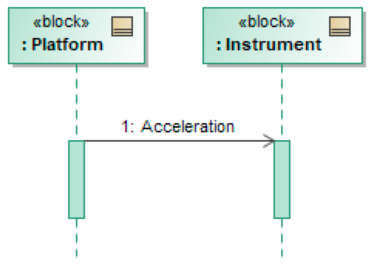
As described in Table 7, the mechanical load requirement is modeled as an energy input to the instrument. The input is characterized as a continuous flow (not a one shot) with the value of the minimum acceleration that the instrument will receive (cf. Figure 15). The diagram in Figure 13 does not show any output. However, this does not imply that the system is not executing any transformation. The full set of requirements needs to be evaluated when making such judgement. In this case, the transformation occurs. It is captured by including Figure 12 and the requirements modeled in Figure 14. The system will execute several outputs (as modeled in Figure 14, which are described below) after it has received the input in Figure 13, as indicated by the strict sequence in Figure 12.
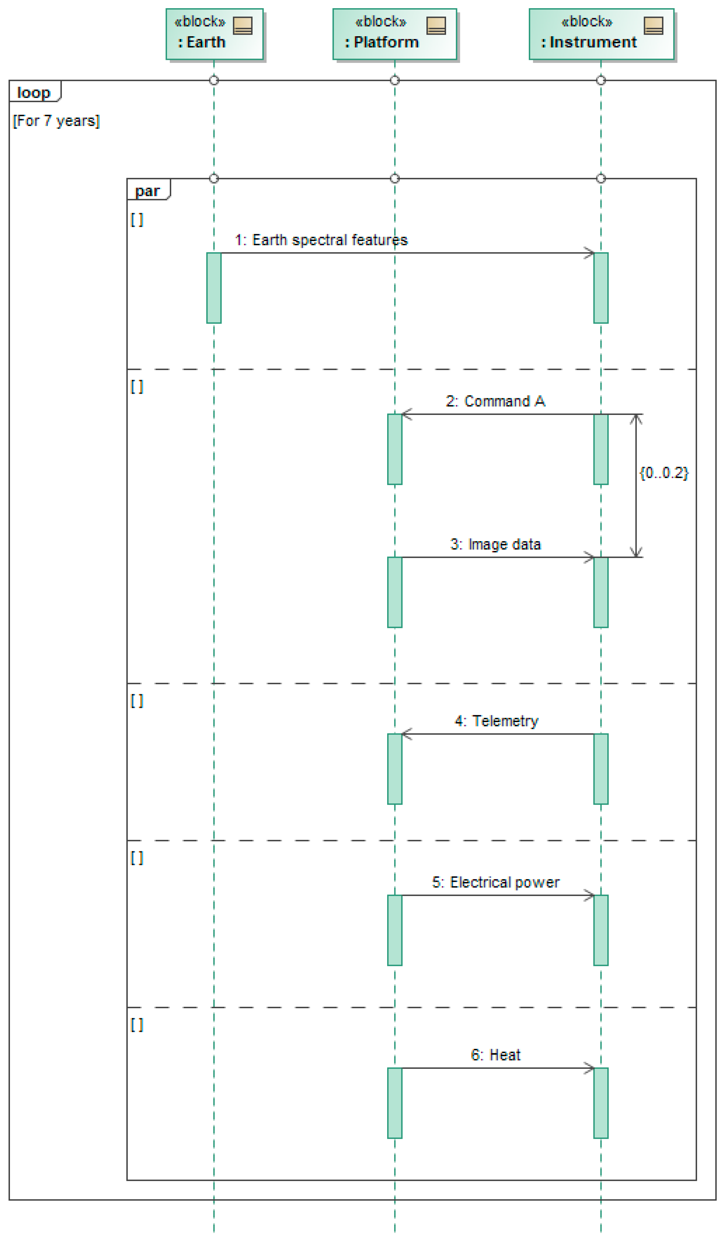
Several aspects in Figure 14 are worth discussing with respect to the Nominal operations requirement set. First, there is a need to leverage the parallel interaction operator because the requirements in the set need to be fulfilled simultaneously. Hence, the diagram represents that the instrument will:
- continuously be exposed to the incoming light from the Earth’s surface, during which
- the instrument will receive a continuous stream of electrical power and thermal energy, and
- will receive commands and be expected to provide image data, and
- is expected to provide telemetry data periodically.
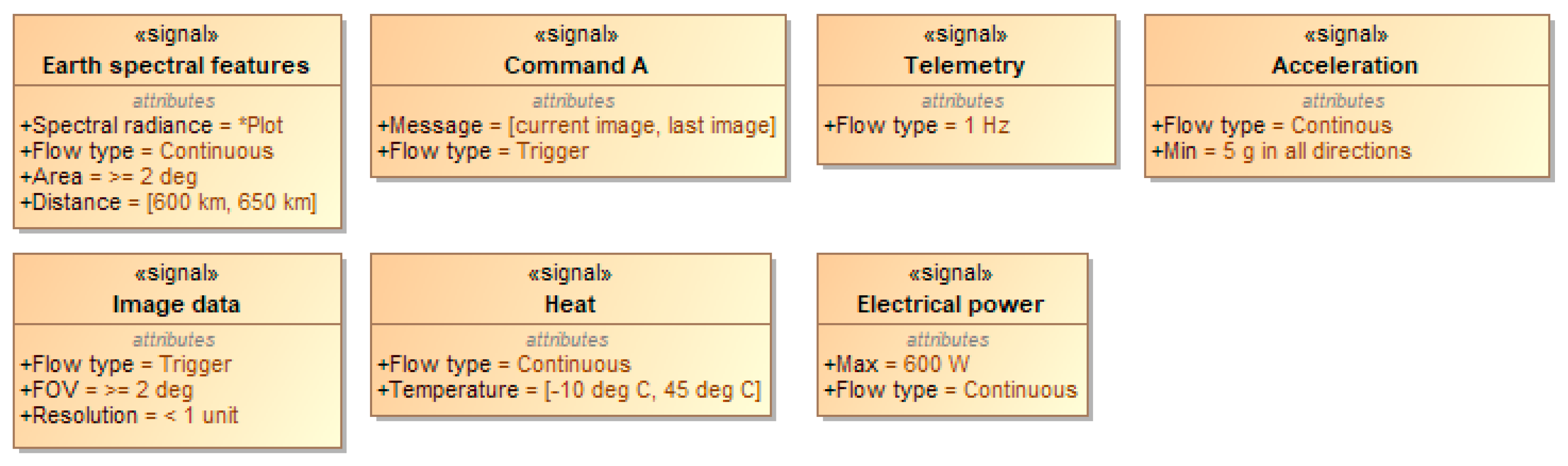
Second, the loop operation operator is used to capture the lifetime requirement. It indicates that the modeled exchange needs to be executed for seven years at least, as stated in Table 7. Third, the temporal nature of different inputs and outputs are captured through properties in the signal elements. Figure 15 shows how they can be used to capture one-off signals (such a trigger), continuous flows (such as energy flux), and periodic signals. In addition, it should be reminded that signal properties can also be defined by linking to parametric diagrams.
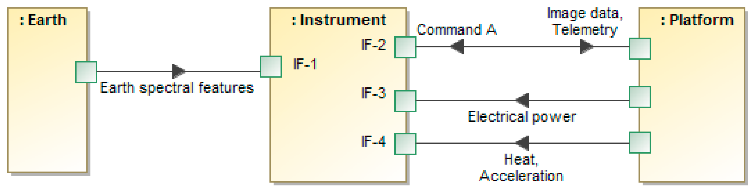
The allocation of inputs and outputs into physical interfaces in Figure 16 captures the four different interfaces identified in Section 4.2. Direction of arrows is consistent with the signals being inputted to or outputted by the instrument, as indicated by the sequence diagrams in Figure 13 and Figure 14.
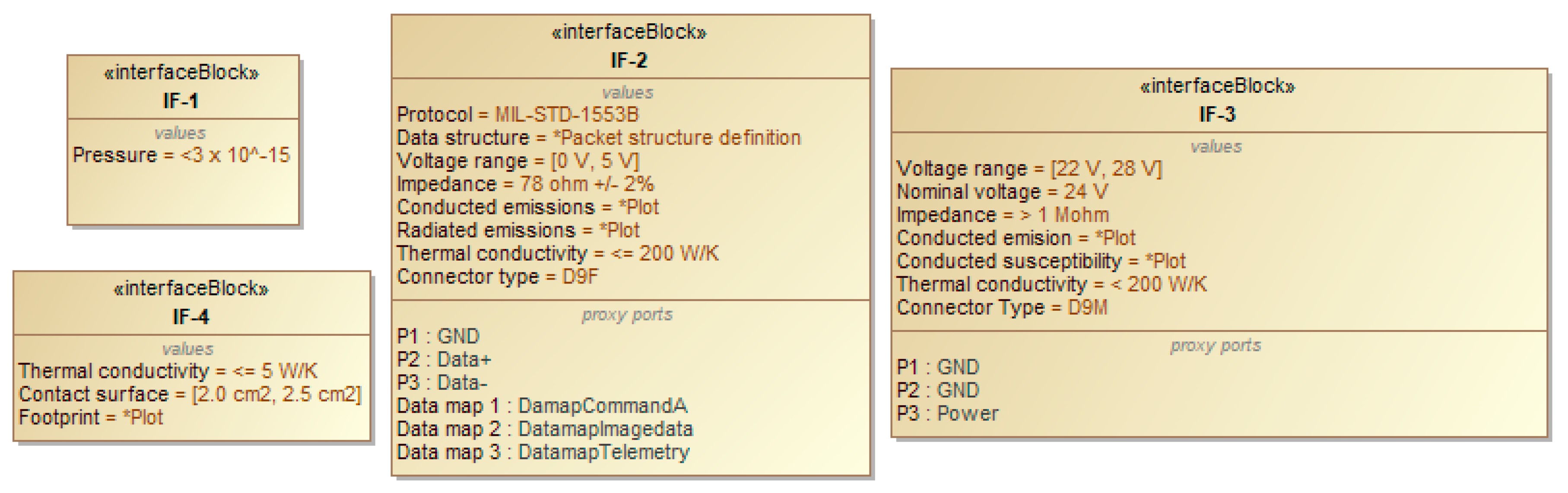
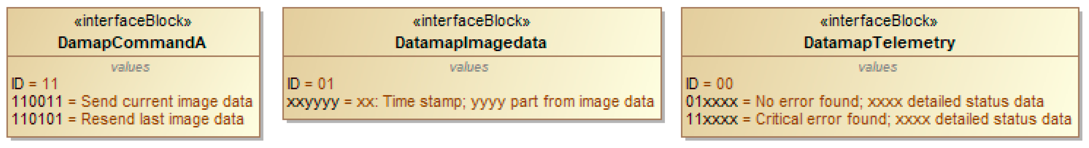
The properties of those interfaces derived from the requirements in Section 4.2 are shown in Figure 17 and Figure 18. Pinout allocation and some aspects of the transport layer have been modeled using proxy ports to avoiding model complexity. In this example, specific meanings of data messages are captured separately and the linked to the physical interfaces (cf. Figure 18). Finally, as was the case for signals, properties could also be linked to parametric diagrams.
Collectively, the models represented in Figure 11, Figure 12, Figure 13, Figure 14, Figure 15, Figure 16, Figure 17 and Figure 18 capture all requirements listed in Table 2 without using shall statements. They provide an example of how requirements can be expressed using only models, which we call in this paper true model-based requirements.
5. Conclusions
An approach to model requirements that leverages and extends SysML has been presented. The approach builds on an internally consistent theoretical framework, which guarantees avoiding formal flaws in terms of bounding solution space. The central proposition of the approach is that every requirement can be modeled as an input/output transformation. As a result, the approach itself forces us to define requirements on the boundaries of the system and inherently avoids over-constraining the solution space unnecessarily. In addition, the central proposition implies that it is not meaningful to distinguish between functional and non-functional requirements. This conceptualization, which departs from existing literature, facilitates consistency. Examples have been provided to show how attributes traditionally allocated to a system and thought of as non-functional (e.g., mass or color) are actually attributes of the inputs and outputs of the system. Furthermore, the paper has shown that the proposed approach to model requirements as transformations can improve precision over using natural language.
Implementation of the approach in SysML is architected as follows:
- (1).
- An extended sequence diagram captures the required logical transformation.
- (2).
- Signals capture logical inputs and outputs with their required attributes.
- (3).
- Ports in block elements capture the physical interfaces and their required properties through which inputs and outputs are conveyed.
- (4).
- An extended state machine diagram is used to capture mode requirements, which capture the simultaneity aspects of requirements applicability.
Author Contributions
Conceptualization, A.S.; Methodology, A.S.; Validation, A.S.; Formal Analysis, A.S.; Resources, A.S.; Writing—Original Draft Preparation, A.S. and P.W.; Writing—Review and Editing, A.S. and P.W.; Visualization, A.S.; Supervision, A.S.; Project Administration, A.S.; and Funding Acquisition, A.S.
Funding
This material was based on work supported by the Acquisition Research Program under HQ0034-18-1-0006. The views expressed in written materials or publications, and/or made by speakers, moderators, and presenters, do not necessarily reflect the official policies of the Department of Defense nor does mention of trade names, commercial practices, or organizations imply endorsement by the U.S. Government.
Conflicts of Interest
The authors declare no conflict of interest. The founding sponsors had no role in the design of the study; in the collection, analyses, or interpretation of data; in the writing of the manuscript, and in the decision to publish the results.
References
- Buede, D.M. The Engineering Design of Systems: Models and Methods; Wiley: Hoboken, NJ, USA, 2009. [Google Scholar]
- Schneidera, F.; Naughtona, H.; Berenbach, B. New Challenges in Systems Engineering and Architecting. In Proceedings of the Conference on Systems Engineering Research (CSER) 2012, St. Louis, MO, USA, 19–22 March 2012. [Google Scholar]
- Helming, J.; Koegel, M.; Schneider, F.; Haeger, M.; Kaminski, C.; Bruegge, B.; Berenbach, B. Towards a unified Requirements Modeling Language. In Proceedings of the 2010 Fifth International Workshop on Requirements Engineering Visualization, Sydney, Australia, 28 September 2010. [Google Scholar]
- Mordecai, Y.; Dori, D. Model-based requirements engineering: Architecting for system requirements with stakeholders in mind. In Proceedings of the 2017 IEEE International Systems Engineering Symposium (ISSE), Vienna, Austria, 11–13 October 2017; pp. 1–8. [Google Scholar]
- Fockel, M.; Holtmann, J. A requirements engineering methodology combining models and controlled natural language. In Proceedings of the 2014 IEEE 4th International Model-Driven Requirements Engineering Workshop (MoDRE), Karlskrona, Sweden, 25 August 2014; pp. 67–76. [Google Scholar]
- dos Santos Soares, M.; Vrancken, J. Model-driven user requirements specification using SysML. J. Softw. 2008, 3, 57–68. [Google Scholar] [CrossRef]
- Adedjouma, M.; Dubois, H.; Terrier, F. Requirements Exchange: From Specification Documents to Models. In Proceedings of the 16th IEEE International Conference on Engineering of Complex Computer Systems, Las Vegas, NV, USA, 27–29 April 2011; pp. 350–354. [Google Scholar]
- Friedenthal, S.; Moore, A.; Steiner, R. A Practical Guide to SysML—The Systems Modeling Language, 3rd ed.; Morgan Kaufman: Waltham, MA, USA, 2015. [Google Scholar]
- Pandian, M.K.S.; Suri, K.; Cadavid, J.; Barosan, I.; Brand, M.; Alférez, M.; Gérard, S. Towards Industry 4.0: Gap Analysis between Current Automotive MES and Industry Standards Using Model-Based Requirement Engineering. In Proceedings of the 2017 IEEE International Conference on Software Architecture Workshops (ICSAW), Gothenburg, Sweden, 3–7 April 2017; pp. 29–35. [Google Scholar]
- Salado, A.; Nilchiani, R.; Verma, D. A contribution to the scientific foundations of systems engineering: Solution spaces and requirements. J. Syst. Sci. Syst. Eng. 2017, 26, 549–589. [Google Scholar] [CrossRef]
- Wymore, A.W. Model-Based Systems Engineering; CRC Press: Boca Raton, FL, USA, 1993. [Google Scholar]
- Salado, A.; Nilchiani, R. A Categorization Model of Requirements Based on Max-Neef’s Model of Human Needs. Syst. Eng. 2014, 17, 348–360. [Google Scholar] [CrossRef]
- Kossiakoff, A.; Sweet, W.N.; Seymour, S.J.; Biemer, S.M. Systems Engineering Principles and Practice, 2nd ed.; John Wiley & Sons, Inc.: Hoboken, NJ, USA, 2011. [Google Scholar]
- Salado, A.; Nilchiani, R. Reducing Excess Requirements through Orthogonal Categorizations during Problem Formulation: Results of a Factorial Experiment. IEEE Trans. Syst. Man Cybern. Syst. 2017, 47, 405–415. [Google Scholar] [CrossRef]
- Badreddin, O.; Sturm, A.; Lethbridge, T.C. Requirement traceability: A model-based approach. In Proceedings of the 2014 IEEE 4th International Model-Driven Requirements Engineering Workshop (MoDRE), Karlskrona, Sweden, 25 August 2014. [Google Scholar]
- Borgne, A.L.; Belloir, N.; Bruel, J.; Nguyen, T. Formal Requirements Engineering for Smart Industries: Toward a Model-Based Graphical Language. In Proceedings of the 2016 IEEE Conferences on Ubiquitous Intelligence & Computing, Advanced and Trusted Computing, Scalable Computing and Communications, Cloud and Big Data Computing, Internet of People, and Smart World Congress (UIC/ATC/ScalCom/CBDCom/IoP/SmartWorld), Toulouse, France, 18–21 July 2016; pp. 1028–1032. [Google Scholar]
- Schmitz, D.; Nissen, H.W.; Jarke, M.; Rose, T. Relating domain model based requirements management and situational method engineering. In Proceedings of the 2010 Third International Workshop on Managing Requirements Knowledge, Sydney, Australia, 27 September 2010; pp. 7–15. [Google Scholar]
- Holt, J.; Perry, S.; Brownsword, M.; Cancila, D.; Hallerstede, S.; Hansen, F.O. Model-based requirements engineering for system of systems. In Proceedings of the 2012 7th International Conference on System of Systems Engineering (SoSE), Genova, Italy, 16–19 July 2012; pp. 561–566. [Google Scholar]
- Holder, K.; Zech, A.; Ramsaier, M.; Stetter, R.; Niedermeier, H.-P.; Rudolph, S.; Till, M. Model-Based Requirements Management in Gear Systems Design Based on Graph-Based Design Languages. Appl. Sci. 2017, 7, 1112. [Google Scholar] [CrossRef]
- Ribeiro, F.G.C.; Pereira, C.E.; Rettberg, A.; Soares, M.S. Model-based requirements specification of real-time systems with UML, SysML and MARTE. Softw. Syst. Model. 2018, 17, 343–361. [Google Scholar] [CrossRef]
- Marschall, F.; Schoemnakers, M. Towards model-based requirements engineering for web-enabled B2B applications. In Proceedings of the 10th IEEE International Conference and Workshop on the Engineering of Computer-Based Systems, Huntsville, AL, USA, 7–10 April 2003; pp. 312–320. [Google Scholar]
- Holt, J.; Perry, S.; Payne, R.; Bryans, J.; Hallerstede, S.; Hansen, F.O. A Model-Based Approach for Requirements Engineering for Systems of Systems. IEEE Syst. J. 2015, 9, 252–262. [Google Scholar] [CrossRef] [Green Version]
- Saadatmand, M.; Cicchetti, A.; Sjödin, M. Toward Model-Based Trade-off Analysis of Non-functional Requirements. In Proceedings of the 2012 38th Euromicro Conference on Software Engineering and Advanced Applications, Izmir, Turkey, 5–8 September 2012; pp. 142–149. [Google Scholar]
- Reza, H.; Sehgal, R.; Straub, J.; Alexander, N. Toward model-based requirement engineering tool support. In Proceedings of the 2017 IEEE Aerospace Conference, Big Sky, MT, USA, 4–11 March 2017. [Google Scholar]
- Lu, C.; Chang, C.; Chu, W.C.; Cheng, Y.; Chang, H. A Requirement Tool to Support Model-Based Requirement Engineering. In Proceedings of the 2008 32nd Annual IEEE International Computer Software and Applications Conference, Turku, Finland, 28 July–1 August 2008; pp. 712–717. [Google Scholar]
- Wanderley, F.; Silva, A.; Araujo, J.; Silveira, D.S. SnapMind: A framework to support consistency and validation of model-based requirements in agile development. In Proceedings of the 2014 IEEE 4th International Model-Driven Requirements Engineering Workshop (MoDRE), Karlskrona, Sweden, 25 August 2014; pp. 47–56. [Google Scholar]
- Cardei, I.; Fonoage, M.; Shankar, R. Model Based Requirements Specification and Validation for Component Architectures. In Proceedings of the 2008 2nd Annual IEEE Systems Conference, Montreal, QC, Canada, 7–10 April 2008; pp. 1–8. [Google Scholar]
- The International Council of Systems Engineering (INCOSE). Guide for Writing Requirements. Available online: https://tcsd.instructure.com/files/99427/download?download_frd=1 (accessed on 13 January 2019).
- Micouin, P. Toward a property based requirements theory: System requirements structured as a semilattice. Syst. Eng. 2008, 11, 235–245. [Google Scholar] [CrossRef]
- Aceituna, D.; Walia, G.; Do, H.; Lee, S.-W. Model-based requirements verification method: Conclusions from two controlled experiments. Inf. Softw. Technol. 2014, 56, 321–334. [Google Scholar] [CrossRef] [Green Version]
- Aceituna, D.; Do, H.; Walia, G.S.; Lee, S. Evaluating the use of model-based requirements verification method: A feasibility study. In Proceedings of the Workshop on Empirical Requirements Engineering (EmpiRE 2011), Trento, Italy, 30 August 2011; pp. 13–20. [Google Scholar]
- Siegl, S.; Hielscher, K.S.; German, R. Model Based Requirements Analysis and Testing of Automotive Systems with Timed Usage Models. In Proceedings of the 2010 18th IEEE International Requirements Engineering Conference, Sydney, Australia, 27 September–1 October 2010; pp. 345–350. [Google Scholar]
- Wach, P.; Salado, A. Can Wymore’s Mathematical Framework Underspin SysML? An Investigation of State Machines. In Proceedings of the Conference on Systems Engineering Research (CSER), Washington, DC, USA, 3–4 April 2019. [Google Scholar]
- Teufl, S.; Mou, D.; Ratiu, D. MIRA: A Tooling-Framework to Experiment with Model-Based Requirements Engineering. In Proceedings of the 2013 21st IEEE International Requirements Engineering Conference (RE), Rio de Janeiro, Brazil, 15–19 July 2013; pp. 330–331. [Google Scholar]
- London, B.; Miotto, P. Model-based requirement generation. In Proceedings of the 2014 IEEE Aerospace Conference, Big Sky, MT, USA, 1–8 March 2014. [Google Scholar]
- von Bertalanffy, L. General Systems Theory—Foundations, Development, Applications; George Braziller, Inc.: New York, NY, USA, 1969. [Google Scholar]
- Tjong, S.F.; Hallam, N.; Hartley, M. Improving the Quality of Natural Language Requirements Specifications through Natural Language Requirements Patterns. In Proceedings of the Sixth IEEE International Conference on Computer and Information Technology, Seoul, Korea, 20–22 September 2006. [Google Scholar]
Figure 1.
Basic Sequence Diagram components.

Figure 2.
Signal attributes to capture required input and output characteristics.

Figure 3.
Basic Internal Block Diagram components.

Figure 4.
Properties of physical interfaces.

Figure 5.
(a) Example of Alternative Path formalism. (b) Example of Parallel Exchanges formalism.

Figure 6.
Example of time dependencies formalism.

Figure 7.
Example of mode requirements.

Figure 8.
(a) Traditional conceptualization of using a locking system. (b) Proposed conceptualization of using a locking system.
Figure 8.
(a) Traditional conceptualization of using a locking system. (b) Proposed conceptualization of using a locking system.

Figure 9.
Three different models of a color requirement, capturing in fact different requirements. (a) The system inherently exhibits color. (b) The system uses electrical power to exhibit color. (c) The system uses incoming sunlight to exhibit color.
Figure 9.
Three different models of a color requirement, capturing in fact different requirements. (a) The system inherently exhibits color. (b) The system uses electrical power to exhibit color. (c) The system uses incoming sunlight to exhibit color.

Figure 10.
Meta-model of the requirements approach in this paper.

Figure 11.
Mode requirements.

Figure 12.
Conditions for applicability of each subset of requirements (Mode transition in Figure 11).
Figure 12.
Conditions for applicability of each subset of requirements (Mode transition in Figure 11).

Figure 13.
Exchange related to the mechanical load requirement.

Figure 14.
Required exchanges in nominal operations.

Figure 15.
Required characteristics of the required inputs and outputs.

Figure 16.
Requirements on the allocation of logical inputs and outputs to physical interfaces through which they must be conveyed.
Figure 16.
Requirements on the allocation of logical inputs and outputs to physical interfaces through which they must be conveyed.

Figure 17.
Required characteristics of the physical interfaces through which inputs and outputs must be conveyed.
Figure 17.
Required characteristics of the physical interfaces through which inputs and outputs must be conveyed.

Figure 18.
Modeling of transport layer aspects as proxy ports for leveraging model complexity.


Table 1.
Requirement taxonomy (dapted from [12]).
Table 1.
Requirement taxonomy (dapted from [12]).
| Req Type | Description | Examples |
|---|---|---|
| Functional | What the system must do | The system shall image the Earth surface in UV spectral range. The system shall transmit image data according to Interface XYZ. |
| Performance | How well the system must perform its functions | The system shall have a resolution better than 1 m. The system shall have a field of view larger than 2°. |
| Resource | What the system may consume to perform its functions at the required performance | The system shall consume less than 200 W. The system shall have a mass lower than 900 kg. |
| Environment | Settings or contexts in which the system must perform its functions | The system shall operate in vacuum. The system shall withstand shock levels higher than ABC. |
Table 2.
Requirements for the optical instrument in natural language (adapted from [12]).
Table 2.
Requirements for the optical instrument in natural language (adapted from [12]).
| Req ID | Description |
|---|---|
| R1 | The instrument shall image a target at 600–650 km according to IF-1. |
| R2 | The instrument shall image a target with spectral radiance of ABC (*plot) according to IF-1. |
| R3 | The instrument shall accept Command A according to IF-2. |
| R4 | The instrument shall transmit image data according to IF-2 in less than 0.2 s after receiving Command A. |
| R5 | The instrument shall have a resolution better than 1 unit. |
| R6 | The instrument shall have a FOV greater than 2°. |
| R7 | The instrument shall provide telemetry data every 1 s according to IF-2. |
| R8 | The instrument shall accept power according to IF-3. |
| R9 | The instrument shall consume less than 600 W of electrical power. |
| R10 | The instrument shall withstand a mechanical load of 5 g in any direction on IF-4. |
| R11 | The instrument shall fulfill its performance when subjected to a temperature between −10 °C and +45 °C at IF-4. |
| R12 | The instrument shall have a lifetime of at least 7 years. |
| Note 1 | R10 only applies during launch. All other requirements only apply once the instrument is powered on through IF-3. |
* These elements are not shown for convenience.
Table 3.
IF-1 description.
| Property | Value |
|---|---|
| Physical layer | |
| Pressure | <3 × 10⁻¹⁵ |
Table 4.
IF-2 description.
| Property | Value |
|---|---|
| Transport layer | |
| Protocol | MIL-STD-1553B 1 |
| Data structure | *Complex definition of packet structures, etc. |
| Data map: Command A | ID: 11 |
| Messages: | |
| 110011: Send current image data | |
| 110101: Resend last image data | |
| Data map: Image data | ID: 01 |
| Messages: | |
| xxyyyy: xx is a time stamp and yyyy parts that form the image data | |
| Data map: Telemetry | ID: 00 |
| Messages: | |
| 01xxxx: No error found, followed by xxxx detailed status data | |
| 11xxxx: Critical error found, followed by xxxx detailed status data | |
| Physical layer | |
| Electrical Properties | |
| Voltage range | [0, 5] V |
| Impedance | 78 ohm ±2% |
| Conducted emissions | *A plot |
| Conducted susceptibility | *A plot |
| Thermal properties | |
| Conductivity | ≤ 200 W/K |
| Connector | |
| Type | D9F |
| Pin allocation | 1: GND |
| 2: Data+ | |
| 3: Data− | |
| … |
1 This is used for illustrative purposes. The data in the table may not be in line with the actual standard. * These elements are not shown for convenience.
Table 5.
IF-3 description.
| Property | Value |
|---|---|
| Physical layer | |
| Electrical Properties | |
| Voltage range | [22, 28] V, nominal 24V |
| Impedance | >1 Mohm |
| Conducted emissions | *A plot |
| Conducted susceptibility | *A plot |
| Thermal properties | |
| Conductivity | ≤ 200 W/K |
| Connector | |
| Type | D9M |
| Pin allocation | 1: GND |
| 2: GND | |
| 3: Power | |
| … |
* These elements are not shown for convenience.
Table 6.
IF-4 description.
| Property | Value |
|---|---|
| Physical layer | |
| Thermal properties | |
| Conductivity | ≤ 5 W/K |
| Contact surface | [2.0, 2.5] cm2 |
| Mechanical properties | |
| Footprint | *Mechanical drawing |
* These elements are not shown for convenience.
Table 7.
Requirements for the optical instrument in natural language (adapted from [12]).
Table 7.
Requirements for the optical instrument in natural language (adapted from [12]).
| Req ID | Strategy |
|---|---|
| R1 | This requirement defines an input that the system must accept. It will be modeled directly as an input signal. |
| R2 | This requirement defines a characteristic of the required input defined in R1. It will be modeled as a property of the signal modeled to capture R1. |
| R3 | This requirement defines an input that the system must accept. It will be modeled directly as an input signal. |
| R4 | The requirement defines an output that the system must provide, as well as the conditions under which the output must be provided. It will be modeled as an output signal and a time dependency with the signal modeled to capture R3. |
| R5 | This requirement defines a characteristic of the required output defined in R4. It will be modeled as a property of the signal modeled to capture R4. |
| R6 | This requirement defines a characteristic of the required output defined in R4. It will be modeled as a property of the signal modeled to capture R4. |
| R7 | This requirement defines an output that the system must provide, as well as the conditions under which the output must be provided. It will be modeled as an output signal occurring in parallel to the exchanges required by R1 through R4. |
| R8 | This requirement defines an input that the system must accept. It will be modeled directly as an input signal. In addition, it will be modeled as a starting event that needs to occur before the exchanges required by R1, R2, R3, R4, and R7 can be executed (since the instrument must be powered in order to fulfill those requirements), and which remains active in parallel with the other exchanges defined in the corresponding mode of operation. |
| R9 | This requirement defines a resource limitation that the system must fulfill, in relation to the required input defined in R8. It will be modeled as a property of the signal modeled to capture R8. |
| R10 | This requirement defines an external environment in which the system needs to operate. It will be modeled as an input signal (mechanical energy) to the system. |
| R11 | This requirement defines an external environment in which the system needs to operate. It will be modeled as an input signal (thermal energy) to the system. |
| R12 | This requirement defines a constraint on how long the system needs to fulfill its requirements. It will be modeled as a duration constraint that describes for how long each transformation needs to be executed. |
| Note 1 | This note defines modes of operation for the system, for which different sets of requirements apply. It leads to define a specific mode (launch) in which R10 applies and another set of modes in which the rest of the requirements apply, as well as the transitions between the modes. |
© 2019 by the authors. Licensee MDPI, Basel, Switzerland. This article is an open access article distributed under the terms and conditions of the Creative Commons Attribution (CC BY) license (http://creativecommons.org/licenses/by/4.0/).
Share and Cite
MDPI and ACS Style
Salado, A.; Wach, P. Constructing True Model-Based Requirements in SysML. Systems 2019, 7, 19. https://0-doi-org.brum.beds.ac.uk/10.3390/systems7020019
AMA Style
Salado A, Wach P. Constructing True Model-Based Requirements in SysML. Systems. 2019; 7(2):19. https://0-doi-org.brum.beds.ac.uk/10.3390/systems7020019
Chicago/Turabian StyleSalado, Alejandro, and Paul Wach. 2019. "Constructing True Model-Based Requirements in SysML" Systems 7, no. 2: 19. https://0-doi-org.brum.beds.ac.uk/10.3390/systems7020019
Note that from the first issue of 2016, this journal uses article numbers instead of page numbers. See further details here.