Application of Model-Based Systems Engineering Concepts to Support Mission Engineering


Department of Systems Engineering, Naval Postgraduate School, Monterey, CA 93943, USA
*
Author to whom correspondence should be addressed.
Systems 2019, 7(3), 44; https://0-doi-org.brum.beds.ac.uk/10.3390/systems7030044
Submission received: 1 July 2019
/
Revised: 15 August 2019
/
Accepted: 29 August 2019
/
Published: 4 September 2019
(This article belongs to the Special Issue Mission Engineering)
Abstract
:This paper presents an approach to the utilization of model-based systems engineering (MBSE) early in the system lifecycle, which focuses on early identification of desirable system characteristics to support mission engineering (ME). The paper relies on the definition of an analysis approach and the associated mapping of architectural products. The analysis strategy focuses on integration of the results of operational simulations and system synthesis models through tradespace visualization. The architectural mapping presents the association of Systems Modeling Language (SysML) products to the analysis strategy. The coordination of these elements is presented as a demonstration of the role that MBSE concepts can play in support of ME. The approach is demonstrated through a case study analysis of a conceptual mine warfare system conducting mine countermeasure operations.
1. Introduction
Two recent emerging concepts, model-based systems engineering (MBSE) and mission engineering (ME), have gained significant traction throughout the domain of systems engineering, as well as within the Department of Defense (DoD). MBSE is largely focused on the creation of consistent system models to improve interoperability, and ME is focused on the definition of a mission (and associated capabilities) as a system that can be designed. Accordingly, integration of the concepts, where ME is conducted based on MBSE fundamentals, may allow for a better means to develop a “mission” systems architecture and conduct mission analysis. This integration has the potential to improve understanding of the tradeoffs available in the selection and integration of system configurations in a mission engineering context.
This paper presents a tailored systems engineering approach that leverages recent trends in MBSE, and that focuses on early identification of desirable system capabilities using both operational simulation models and system synthesis models. This approach is motivated by and tailored to the recent DoD emphasis on the utilization of analytic data to support decision making. More specifically, the utilization of MBSE to support ME directly leverages system architectures as the basis for the development and analysis of detailed system synthesis models and detailed operational system models. Accordingly, this paper is organized into: presentation of foundational research in both MBSE and ME, definition of the application of MBSE fundamentals to support ME, and a demonstration of the utility of the approach.
2. Background and Motivation
2.1. Model-Based Systems Engineering
The International Council on Systems Engineering (INCOSE) formally defines five intended benefits of MBSE: improved communications, increased ability to manage system complexity, improved product quality, enhanced knowledge capture and reuse of information, and improved ability to teach and learn systems engineering fundamentals [1]. Various MBSE methodologies exist, many of which have been developed to support the realization of the intended benefits of MBSE in a particular domain. This paper develops a framework for the application of MBSE techniques, with a particular focus on the integration of system architecture products with system analysis techniques, to support mission level engineering. More specifically, it presents a MBSE approach specifically tailored to analyze the operation of large scale, complex systems early in the system development lifecycle using external models and simulations, such as those developed in MATLAB/Simulink, ExtendSim, SimPy, AnyLogic, NetLogo, or other simulation software packages.
Within the domain of MBSE, substantial effort has been spent on the creation of a standardized system architecture modeling language, the Systems Modeling Language (SysML). SysML is defined concisely in [2] as “a general-purpose graphical modeling language that supports the analysis, specification, design, verification, and validation for complex systems.” Note that this aligns almost perfectly with the INCOSE definition of MBSE as “the formalized application of modeling to support system requirements, design, analysis, verification and validation activities beginning in the conceptual design phase and continuing throughout development and later life cycle phases” [3]. This makes it clear that SysML is intended to be a primary enabler of MBSE, which itself is a method to enable the successful execution of an end to end systems engineering effort. That emphasis can be seen in the scope of SysML products (Requirements Diagrams, Activity Diagrams, Sequence Diagrams, State Machine Diagrams, Use Case Diagrams, Block Definition Diagrams, and Internal Block Diagrams) as well as the development of various MBSE methodologies (notable examples include INCOSE Object Oriented Systems Engineering, IBM Harmony for Systems Engineering, Vitech Corporation’s Model-Based Systems Engineering Methodology, and NASA’s Jet Propulsion Lab State Analysis) that demonstrate the use of SysML as an enabler of MBSE.
Recent MBSE research, in particular [4,5,6,7,8], has focused on expanding the conceptualization of MBSE beyond the development of system architecture models utilizing SysML to the development of system synthesis models, operational system models, and tradespace visualization based on an existing system architecture. That work has, often necessarily, restricted model development and analysis to a single demonstration of either a system synthesis system model or an operational simulation model.
Recent analysis work based on MBSE fundamentals has demonstrated the potential utility of examining both system synthesis models and operational system models concurrently. Existing approaches endeavor to link design efforts, operational analysis, and tradespace study to fully realize the intended benefits of MBSE. Notably, Spyropouos [9] presents a method for integration of SysML with trade-off analysis tools. Ryan et al. [10] apply MBSE to requirements engineering. Kapos et al. [11] demonstrate conversion of SysML to discrete event simulation models. Spero et al. [12] present a review of the utilization of executable models for tradespace analysis for resilient systems. Bleakley et al. [13] discuss a method for using SysML to explore the design space through execution analysis. Duncan et al. [14] utilize SysML to produce performance trade studies. McKean et al. [15] utilize a model-based architecture to conduct component level trade studies using Harmony SE. Huff et al. [16] evaluate system models to assess alternative designs for critical infrastructure using multiple models. MacCalman et al. [17] use efficient experimental designs for identifying tradeable variables. Maheshwari et al. [18] develop integrated SoS Analytics Workbench capabilities tied to MBSE artifacts to conduct SysML-based analysis through simulation. LaSorda et al. [19] develop a model-based architecture to optimize coordinated satellite deployment, the findings of which are generalized and presented as a method for effective MBSE in [20]. These recent efforts have expanded the conceptualization of MBSE and demonstrated the applicability and impact that it may have for the development of a broad range of systems. This paper expands that recent work through the description and demonstration of a mission focused application of MBSE concepts.
2.2. Mission Engineering
While MBSE is focused on the development and delivery of appropriate systems, ME is focused primarily on the appropriate utilization of those systems. Candidate definitions from [21,22,23] reinforce that focus on organizing the utilization of systems. Specifically, Gold [22] presents ME as the “deliberate planning, analyzing, organizing, and integration of current and emerging operational and system capabilities to achieve desired warfighting mission effects.” In an idealized implementation, ME results in “an assessment framework to measure progress toward mission accomplishment through end-to-end system integration of test and evaluation of mission threads” [22]. Recent research [24] refines the initial ME model through simultaneous consideration of integration, operations, and acquisition for the relevant systems and provides the first step toward developing the assessment framework suggested by [22]. This refinement introduces mission engineering and analysis (MEA) and includes a mission plan as part of the system, with an emphasis on constant analysis and assessment throughout the mission cycle. This mission plan merges systems engineering processes with military decision-making processes as outlined in U.S. Army doctrine. While recent ME efforts have focused on the definition of an initial concept for mission engineering, this research advances current efforts in the following areas:
- Application of systems engineering best practices to the associated systems and systems of systems that support operational mission outcomes. This is an expansion of [24] through the development and demonstration of a MBSE methodology that explicitly considers mission outcomes.
- Development of a means to go “beyond data exchange among systems to address cross cutting functions, end to end control and trades across systems.” [22]. Our application of MBSE to ME demonstrates a strategy for understanding system functions and their inter-relationships, and provides a means of quantifying the decision tradespace.
3. Approach
3.1. MBSE to Support Analysis
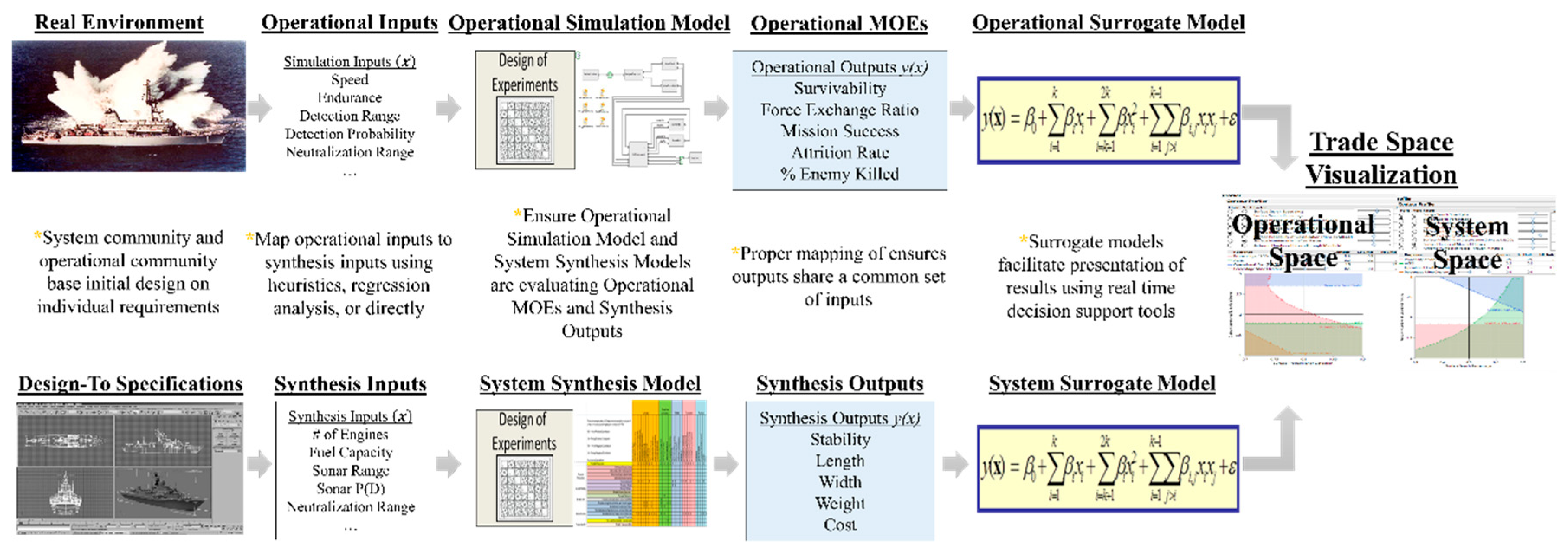
The overall intent of this research is to provide a demonstration of ME, grounded in MBSE fundamentals, that enables development of large-scale systems through analysis of models and simulations. In particular, the approach is focused on the utilization of MBSE fundamentals to support the development and analysis of both operational simulations and system synthesis models. Operational simulation models are defined consistent with [17] where “an operational model simulates a system performing a mission within a predetermined environment or scenario” and system synthesis models are defined similarly from [17] where “engineers use physics-based, first-order engineering, or synthesis models to understand the physical constraints that determine a feasible system design.” Accordingly, a foundational analysis methodology, which is supported by the broader MBSE approach, is useful to bound the scope of the engineering effort. Figure 1, based on [25,26] provides a starting point for identifying the characteristics of an MBSE-based analysis methodology. It establishes a formal linkage between operational need and physical system configurations and serves as the basis for the MBSE-based analysis methodology.
Figure 1 presents a left to right perspective on the methodological building blocks inherent to any MBSE-based analysis process. Critically, the approach considers two distinct, parallel processes, the operational design of the system (shown on the upper portion of Figure 1) and the physical design of the system (shown on the lower portion of Figure 1).
Operational design of the system begins with the definition of the Real Environment in which the system is expected to operate and development of Operational Inputs that characterize the associated system. Throughout this paper a naval mine countermeasures vessel will be used as an example. The Operational Inputs (e.g., Speed, Endurance, Detection Range, Detection Probability, etc.) are evaluated in an Operational Simulation Model. The purpose of the operational simulation model is to establish a linkage between these model inputs to an operationally relevant set of model outputs (listed in Figure 1 as Operational MOEs). Through the use of proper experimental designs, the linkage of the model inputs to model outputs, or measures of effectiveness (MOEs) can be represented in a statistically valid surrogate model, or regression model, which can subsequently serve as a surrogate to the simulation itself. The use of such a surrogate model allows for a rapid examination of the relationships between model inputs and outputs. As an example, it would be possible for a minimum acceptable performance standard to be set for one of the MOEs (e.g., Attrition Rate) and the set of ships capable of satisfying that performance standard could be defined (e.g., the ships with sufficient Speed, Endurance, Detection Range, Detection Probability, and Neutralization Range to satisfy the standard for Attrition Rate).
Note that while the description of Figure 1 could have been initiated with a decomposition of the operational design process or the physical design process, the authors consciously chose to begin with the operational design process. Rather than defining the desired ship (or system) in terms of a preferred ship length, ship beam, ship displacement, radar range, number of guns, etc., and subsequently assessing the ability of that ship to meet various performance criteria, the analysis methodology advocates beginning the design process by considering the performance criteria. If done properly, the analysis methodology should prevent the development of any system that does not directly support specific Operational MOEs (as well as any system that does not provide satisfactory performance with respect to each of those Operational MOEs). This explicit coupling and ordering of operational analysis and system design is intended to mitigate the risk of entering into a sequence where physical systems are developed and subsequently analyzed to determine performance, which may result in the development of systems without an emphasis on functionality.
While developing and analyzing operational simulation models, the analysis methodology specifies a process for development and analysis of system synthesis models (as shown in the bottom of Figure 1). The modeling approach is nearly equivalent to the operational simulation models. Synthesis Inputs (in this case, Number of Engines, Fuel Capacity, Sonar Range, Sonar P(D), etc.) are linked to Synthesis Outputs (Stability, Length, Width, etc.). Analysis of the output results in development of a surrogate model that rapidly reproduces the results of any system synthesis model. Introduction of design standards (such as maximum acceptable ship length, maximum acceptable displacement, etc.) prompts assessment (using the surrogate models) of the feasibility of those design standards for a given set of ship characteristics (Speed, Endurance, Detection Range, Neutralization Range, etc.). Linkage of modeling results is possible because the system synthesis models and the operational synthesis models have the same inputs (with some potential mapping, such as Endurance to Fuel Capacity).
If done properly, this linkage of modeling results facilitates simultaneous presentation of the results of operational simulation models and system synthesis models. Simultaneous and dynamic examination of the operational and system space is possible after analysis of the modeling results and development of surrogate models. This facilitates examination of a significant portion of the tradespace, which we have modeled in both the operational and physical domain, rather than a single design recommendation based on some form of multi-objective optimization.
3.2. MBSE to Support ME
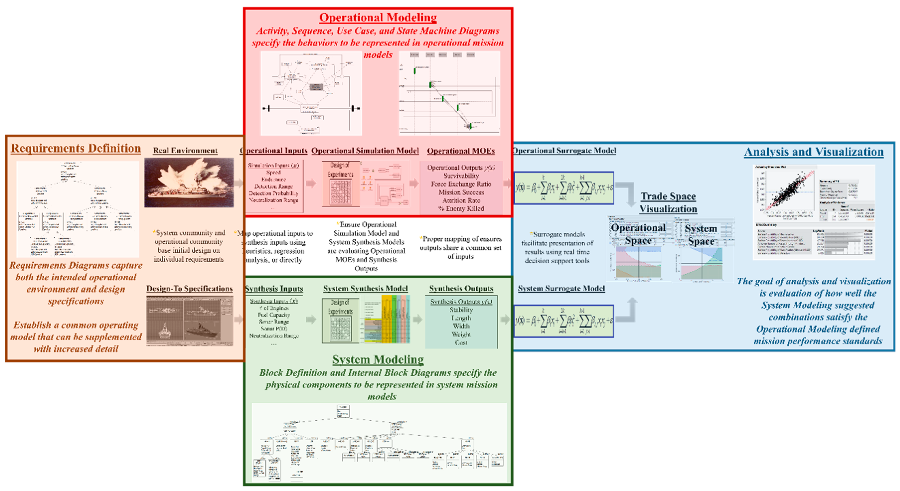
The linkage of model inputs suggested by the analysis approach can pose a substantial challenge. To fully realize the benefits of the analysis approach as an extension of both MBSE and ME, it must be tied to fundamental concepts in each area. Specifically, the focus on operational and system capabilities leads to an architecture development strategy for ME that is well aligned with existing SysML products. By relying on the set of allowable relationships and data standards prescribed by SysML, it is possible to expand the MBSE focused analysis approach presented in Figure 1 to guide development of architecture products to support mission engineering. This research establishes Figure 2 as a sequenced expansion of the analysis methodology (Figure 1) with SysML products as a baseline to guide the application of MBSE fundamentals to the ME domain.
Note that Figure 2 is defined by multiple overlaid steps that facilitate the execution of the Analysis Approach detailed in Figure 1. The application presents four distinct steps: Requirements Definition, Operational Modeling, System Modeling, and Analysis and Visualization. SysML modeling enables the majority of the approach. Experimental design selection, simulation analysis, and tradespace analysis facilitate the utilization of MBSE to support ME in conjunction with those architecture products. The subsequent section demonstrates the potential utility and applicability of the utilization of MBSE to support ME through an analysis of the early stage design for a naval mine warfare system.
4. Demonstration
4.1. Requirements Definition
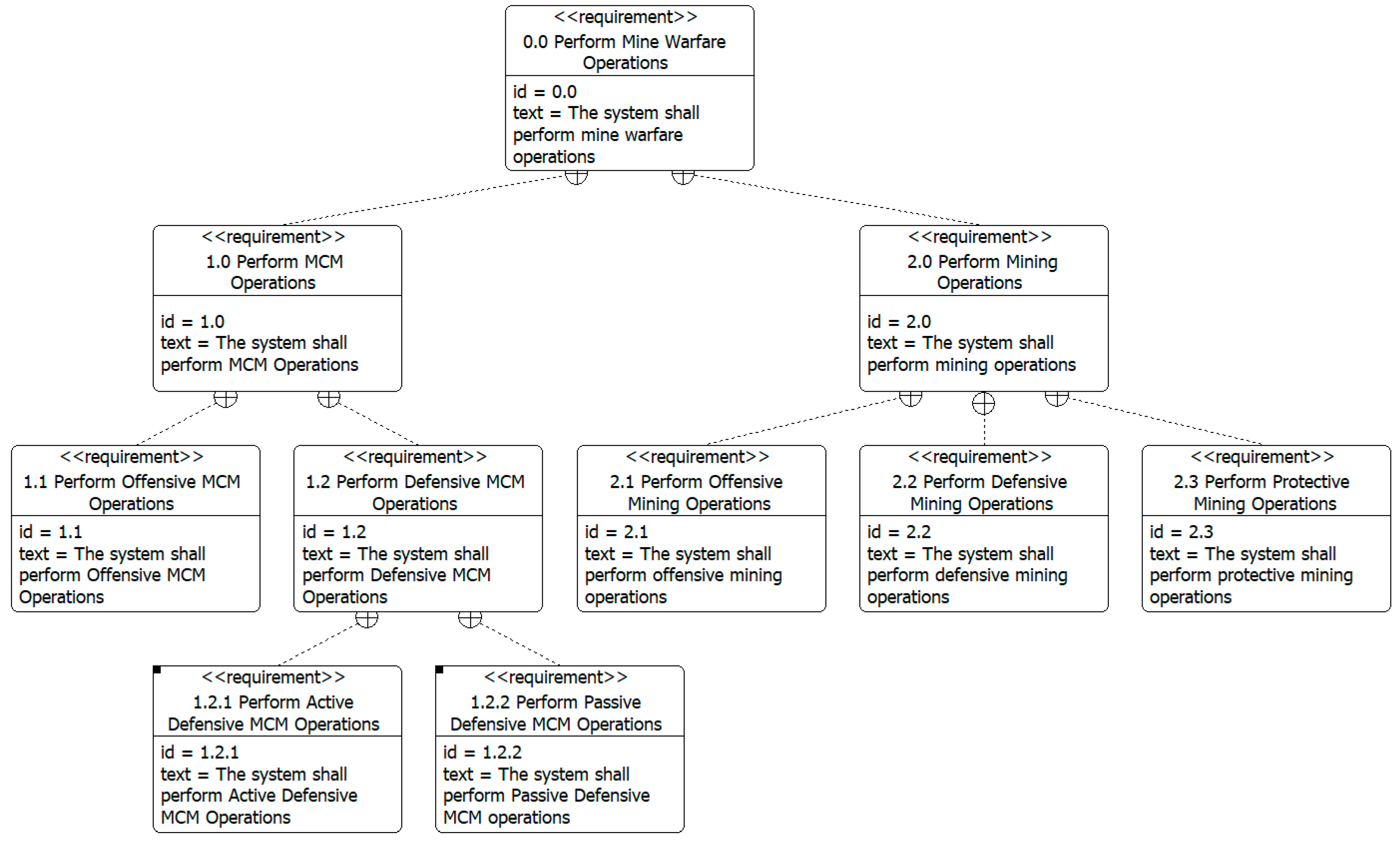
As noted in Figure 2, the application of MBSE to support ME is initiated by the generation of a Requirements Diagram. Note that the generation of these requirements assumes that a stakeholder analysis has been conducted and an initial set of requirements has been developed (this research does not assume that these requirements are necessarily appropriate and investigation of the appropriateness of those requirements is a major focus of both MBSE and ME that is supported through the linkage of the two domains).
A comprehensive Requirements Diagram communicates a clearly defined problem system boundary, system objectives, and initial system capabilities. The requirements capture the operational environment and design specifications for the system in terms of intended capabilities, expected functions, and quantified performance conditions. Figure 3 presents an example Requirements Diagram for a conceptual mine warfare (MIW) system (the authors use Vitech CORE for the development of the architecture products; note that an equivalent architecture could be generated in an alternative software package such as MagicDraw, Innoslate, etc., depending on stakeholder preferences). Figure 3 provides a hierarchy of requirements that address “Perform Mine Warfare Operations” and shows the functions that are assigned to each requirement (top half of each box). The quantified performance condition for each requirement is included in the CORE file, but not shown in this graph for the sake of brevity and simplicity.
4.2. Operational Modeling
Given that the focus of mission engineering is operation of the system of interest, architectural development for mission engineering requires a comprehensive definition of the mission functional architecture. The functional architecture summarizes the system in terms of HOW it will satisfy the requirements identified in Step 1 (Requirements Definition), but does not necessarily define what physical system elements will satisfy those requirements. Development of SysML Activity, Sequence, State Machine, and Use Case Diagrams support this definition. Further, the definition of the set of sequenced activities, the state dependent transitions between those activities, and the users responsible for the execution of each of those activities guides the development of external operational simulation models.
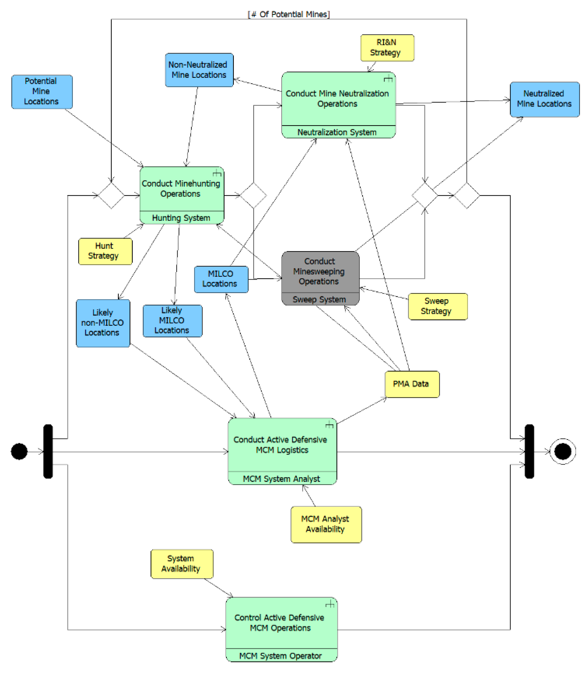
In support of ME, Activity Diagrams are a reasonable starting point for the development of functional architecture products for several reasons. Not only do Activity Diagrams describe what the system must do to perform the mission, they also describe the external objects that are necessary to complete or trigger each function that defines the mission. Activity Diagrams can also model parallel and alternate operations, loops, iterations, and replications of activities. Also notable is the ability to group activities into partitions (also called swim lanes) that allow a user to specify responsibility (in terms of model parameters) regarding the execution of those activities. While most activities must be completed to trigger subsequent activities, some activities within these partitions can be specified as interruptible if any stop or delay in that activity does not impact any other actions or activities. While these characteristics are understandable through narrative text, they are more easily visualized and understood through examination of the diagrams. As mentioned, the sequenced presentation of figures in this chapter demonstrates the fundamental elements and structure of each diagram in detail (to include highlighting traceability and consistency between diagrams) and demonstrates their utility in the development of external simulation models. Figure 4 presents an Activity Diagram for Active, Defensive Mine Countermeasures (MCM) Operations.
The Activity Diagram shown in Figure 4 demonstrates that there are three parallel processes associated with Active, Defensive MCM Operations: a sequence of Minehunting, Mine Neutralization, and Minesweeping; Active Defensive MCM Logistics; and Control of Active, Defensive MCM Operations. The parallel nature of these activities suggests that it may be necessary to concurrently allow for each of them within an external simulation model. The Activity Diagram also specifies that after Minehunting Operations conclude there is a choice between Mine Neutralization Operations and Minesweeping Operations. Moving forward, this research will focus on Mine Neutralization Operations rather than Minesweeping Operations (Minesweeping Operations has accordingly been shaded in gray by the authors). Note that the Activity Diagram also specifies the external components that will be created and used by each activity, which provides details regarding the physical entities that must be represented in an external simulation model. Specifically, two classes of entities are of particular interest, information regarding the mine locations (shown in blue in Figure 4) and information regarding control and operation of the Active Defensive MCM Operations (shown in yellow in Figure 4). Note that mine location information can be traced almost sequentially from left to right, when Potential Mine Locations at the start of the process become Neutralized Mine Locations through the execution of the Minehunting, Mine Neutralization, and MCM Logistics activities. The control and operation information is less traceable given that the information concerns strategy and availability and is therefore set as an input to each activity when necessary, but does not necessarily result in a defined output from that activity.
Given their sequential nature and clearly segmented activities, the Activity Diagrams are intuitive starting points to support mission definition. Sequence Diagrams, Use Case Diagrams, and State Machine Diagrams can be used to provide supplementary information regarding mission performance. Sequence Diagrams are particularly useful to provide a different view of interactions between elements of the internal structure of an activity, which helps provide clarity regarding the ordering of activities. Specifically, it should alert any user to conflicts that may result from expecting an activity to commence prior to the creation of external information necessary to support that activity, a level of detail that is more difficult to see when using only Activity Diagrams as they provide no detail regarding the control of activity inputs or outputs while modeling at the level of abstraction shown. Use Case Diagrams can be used to further aid development of functional architecture views by providing an increased level of detail regarding the actors that are involved in each activity. Use Case Diagrams are particularly useful for multi-purpose systems, which may require a different set of personnel to execute each activity. Used in conjunction with Sequence Diagrams, this allows a mission engineer to identify potential conflicts in terms of both system control and system implementation. Finally, State Machine Diagrams provide additional clarity regarding the range of behaviors possible for a given entity, as well as the differing modes of activities in different states. This allows for a more formal examination of the control system of the system of interest than is possible in the Activity Diagram. Given that the process of interest (Minehunting and Mine Detection) is a sequential, discrete process with a limited number of human interactions and state changes, both the Use Case and State Machine Diagrams are not particularly interesting and are not shown.
The appropriate combination of Activity, Sequence, Use Case, and State Machine Diagrams defines the mission comprehensively from a functional perspective. The mission engineer can completely describe the sequencing of system activities, which can be used as a basis for model development. The mission engineer can also formally present limitations to system performance, whether they arise from some alteration to system environmental conditions (as identified in a State Machine Diagram), some issue with personnel availability (as identified in Use Case Diagrams), or some issue with system control (which, depending on implementation, may be represented in either a State Machine or Sequence Diagram), that must be represented in an external model.
4.3. System Modeling
A system modeling perspective is necessary to more completely describe the mission in terms of the physical entities that perform the functions in Activity Diagrams, Sequence Diagrams, Use Case Diagrams, and State Machine Diagrams. Block Definition Diagrams decompose physical entities, which are only shown in a general sense in each of the Functional Architecture products, into more detailed components. One of the major advantages of Block Definition Diagrams is that they allow complete representations of the potential physical configurations of a system, even if components are mutually exclusive. In the case of the MIW System, this allows for the creation of the physical elements associated with each design alternative, even those designs that cannot physically feasibly exist together. Internal Block Diagrams expand this functionality by establishing a connection between Block Definition Diagrams and Activity Diagrams by specifying how the elements shown in the Block Definition Diagrams perform the activities shown in Activity Diagrams to achieve the intended functionality of the system. As with the Use Case and State Machine Diagrams, interested readers are directed to [26] as the detailed presentation of the specific diagrams is beyond the scope of this paper. For the purpose of this paper, the Physical Architecture resulted in a definition of alternative system designs, which were defined by a total of 34 Design Parameters (29 system design characteristics such as system speed and sonar probability of detection as well as five Environmental/Operational Variables such as the number of passes each system takes through the minefield as well as the staging distance for support systems).
As a note on system modeling, it is difficult to provide a complete demonstration of the utility of SysML products through the presentation of static figures. While these figures do provide a defined picture of the major functional and physical properties of potential systems, it is difficult to present the level of detail associated with the connections between each of the diagrams. Much of the value of a coordinated set of architecture products is that changes to system requirements, functions, elements, etc., in one diagram will promulgate through each diagram, substantially reducing the need for rework and providing nearly instantaneous checks on consistency between the functional and physical representations of a system. While this is certainly a limitation of architecture presentation through static figures, a sufficient level of detail has been presented to guide the development of an external model of Active, Defensive MCM operations based on the SysML architecture products.
4.4. Analysis and Visualization
4.4.1. Mission Model Description
Completion of system modeling (enabled by the creation of Block Definition and Internal Block Diagrams) describes a mission in terms of the participating systems. The Requirement Diagram describes a mission in terms of stakeholder satisfaction. The Activity, Sequence, Use Case, and State Machine Diagrams describe a mission in terms of operational implementation. While these products enable a complete description of a mission from multiple perspectives, they do not enable detailed analysis of the performance of that mission, per the application strategy presented in Figure 2. Proper analysis requires definition and analysis of external mission models.
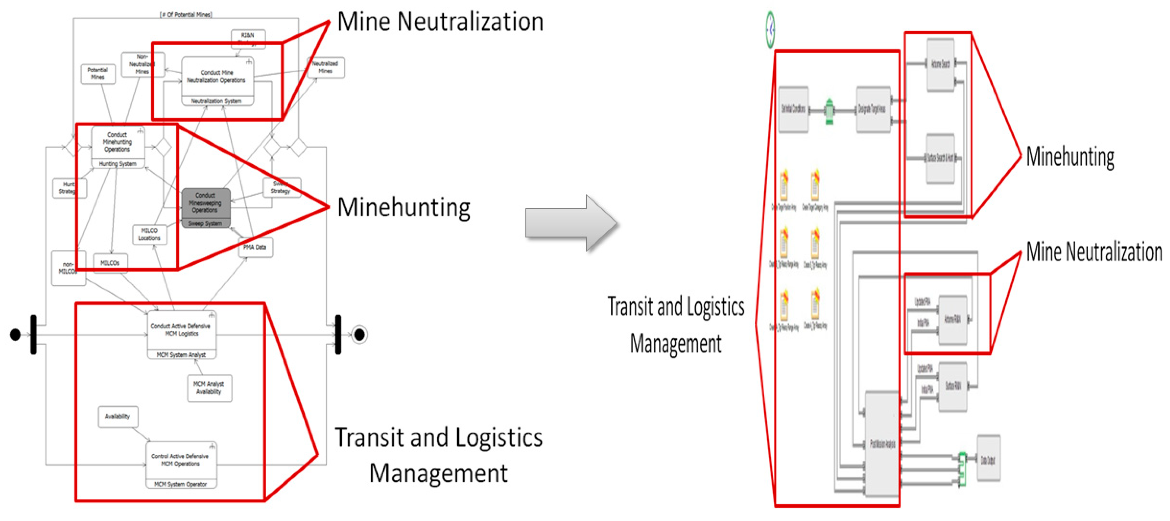
The application of MBSE to support ME utilizes the combined operational and system modeling products as a basis for the development of an external system model. In particular, the Activity, Sequence, Use Case, and State Machine Diagrams specify the components, behaviors, and processes represented in the external model. The Block Definition and Internal Block Diagrams specify the set of components, component interfaces, and constraints represented in the external model. This utilization of analysis procedure external to the SysML modeling process prevents any oversimplifications of system performance that may occur if sufficiently detailed modeling of mission performance is not conducted. For the purposes of this research, a discrete event simulation developed in ExtendSim was utilized. Detailed examination of the associated SysML products suggests that the discrete event simulation must represent three distinct stages of operation: transit to and from the minefield, minehunting, and mine neutralization. As noted, the purpose of operational and system modeling is to guide the development of more detailed system models, accordingly, Figure 5 presents a mapping of the Activity Diagram presented in Figure 4 to the ExtendSim model developed as a demonstration for this research.
Note that appropriate experimental design selection is vital to ensure that alternative mission implementation options are examined properly. Simply establishing a baseline alternative and conducting evaluation through isolated excursions is inappropriate. For the purposes of this research, a nearly orthogonal balanced (NOB) design, as defined in [27], is utilized to examine the 34 Design Parameters identified in the Physical Architecture. The design prescribed a set of 512 mission implementation combinations for investigation. To account for the variability associated with the model, each combination was replicated 30 times, for a total of 15,360 total Design Parameter combinations.
4.4.2. Mission Model Analysis and Verification
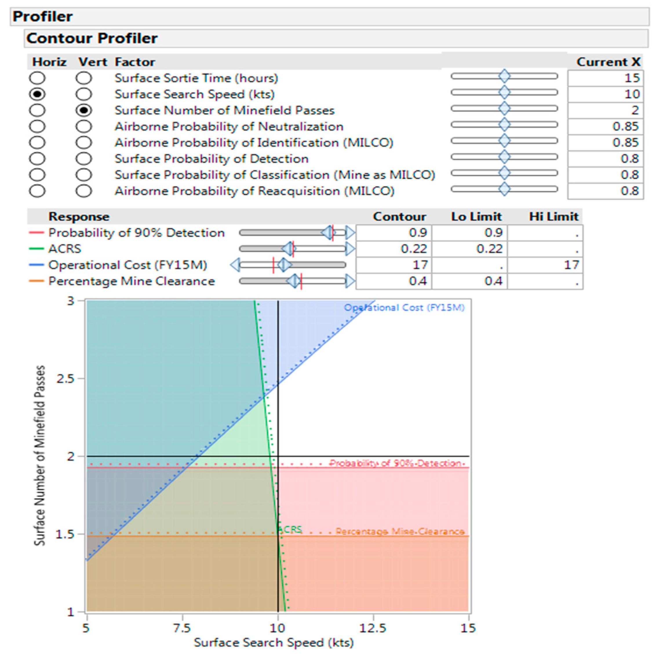
The objective of utilizing MBSE fundamentals to support ME is to identify desirable system configurations to enable mission execution. That desirability is a function of the MOEs developed for the system of interest. For this demonstration, the performance of each system configuration is evaluated in terms of four MOEs: the probability that the system clears 90% of all targets, the Area Coverage Rate Sustained (ACRS) (as defined in [28]), the operational cost (as defined in [29]), and the percentage of all mines cleared. Regression analysis suggested that eight design parameters had a statistically significant impact on the operational effectiveness or cost of the system. As with the architectural diagrams, detailed analysis of each MOE is included in [26] for interested readers. The eight design parameters that had a statistically significant impact on system effectiveness and cost were explored in more detail using a tradespace analysis approach. For the purposes of this demonstration, a contour profiler was used to identify system configurations that are feasible from an operational (in terms of probability of 90% clearance, ACRS, and percentage clearance) and synthesis (in terms of cost) perspective. As mentioned, eight variables had a statistically significant impact on one or more MOEs; this demonstration focuses on the search speed (shown on the x-axis of Figure 6) and the number of minefield passes (shown on the y-axis of Figure 6). This demonstration assumes that constraints have been imposed for each MOE, with a threshold of 90% for the probability of 90% detection, a threshold of 40% for percent clearance, a threshold of 0.22 for the ACRS, and a threshold of $17million for the operational cost. The set of feasible system configurations are shown in white in Figure 6.
The tradespace approach is particularly useful at communicating that there is not a single acceptable system configuration for executing a mission, rather a feasible set of system configurations are identified. In this example, the crosshairs indicate a potential design point. Note that the system must have a search speed of at least 10 knots if two minefield passes are conducted (design points with a lower speed will be unable to satisfy the constraint for ACRS).
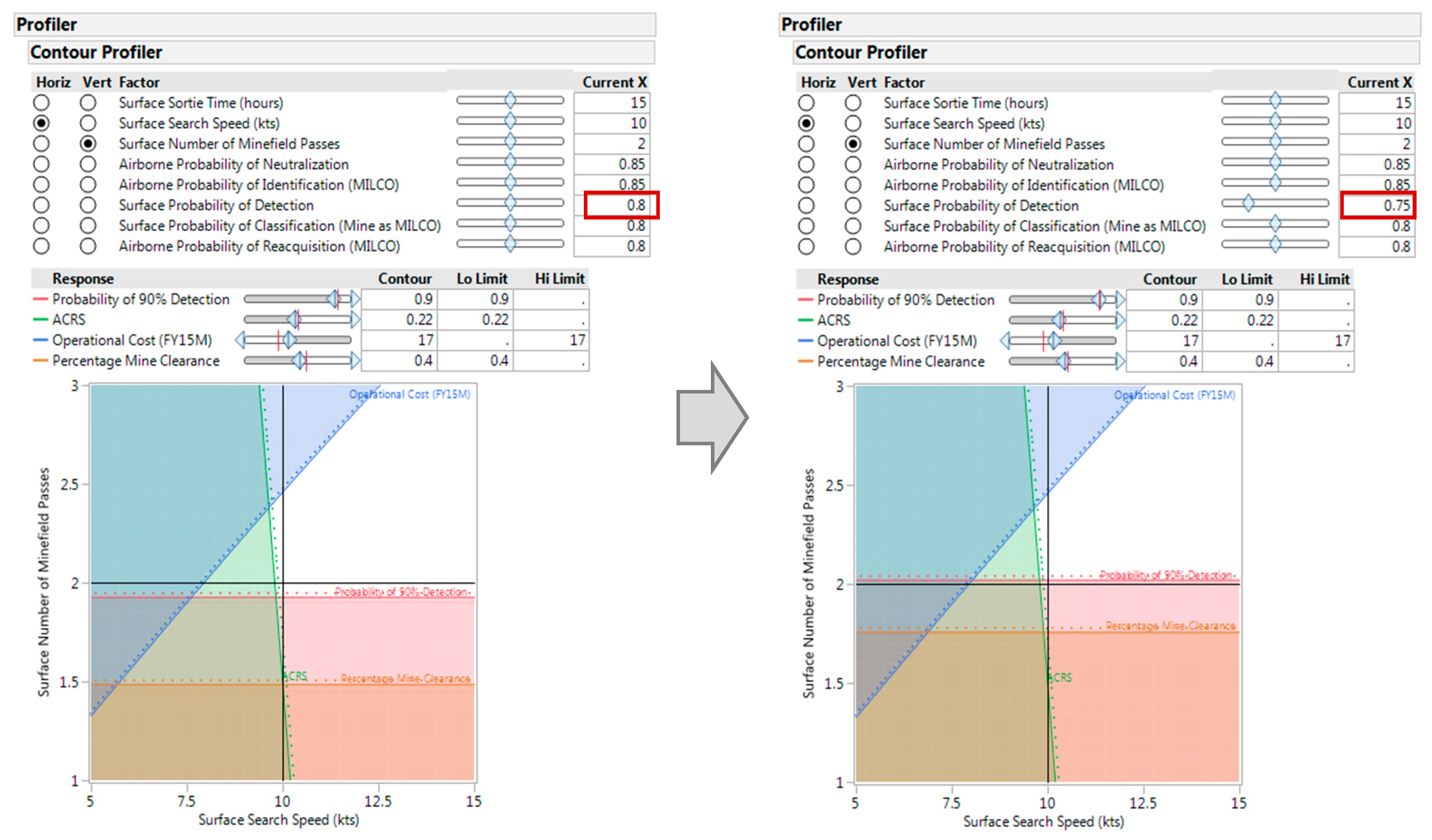
One major point that should be emphasized is that the feasibility of a given design in the two-dimensional projection of the design space shown in Figure 6 is sensitive to changes to other design parameters. As an example, Figure 7 presents a snapshot of the impact of changing the sonar probability of detection (assumed in Figure 6 to be 0.80) to 0.75.
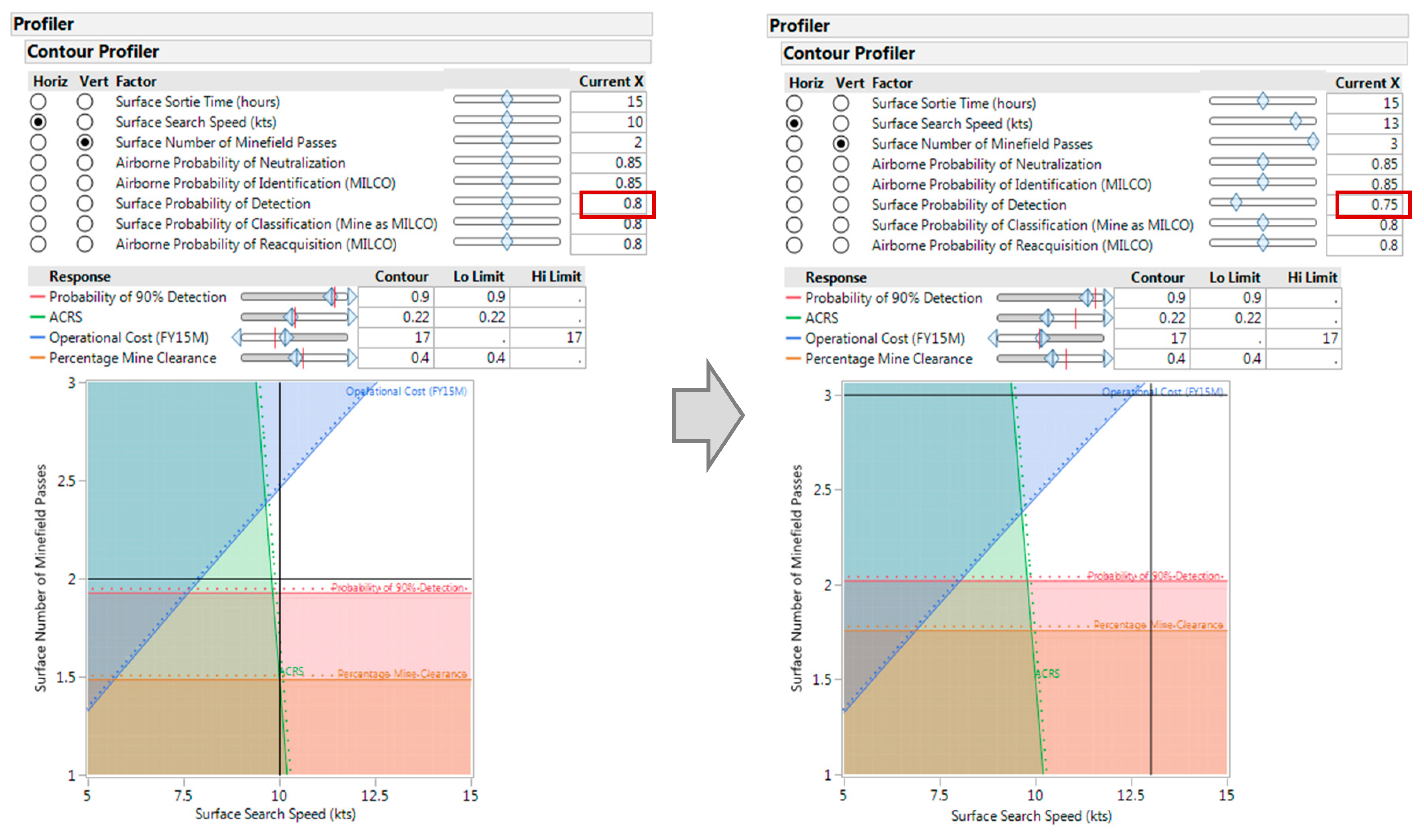
While this is an instructive example of the challenges that can arise as a result of alterations to system configuration, the tradespace exploration approach also suggests multiple potential solutions. Figure 8 presents an example of a solution that is easily apparent and focused on mission implementation: the system that is made infeasible by the reduction in sonar probability of detection to 0.75 becomes feasible again when the mission is changed to increase the number of minefield passes from 2 to 3.
5. Conclusions and Future Work
Utilization of MBSE to support ME is a potential approach to improve the development and design of systems to support mission execution. Specifically, this approach has the potential to help with the identification of alternative ship and fleet designs for the U.S. Navy, although applicability to other domains is certainly possible. The application of MBSE to support ME presented in this paper provides a roadmap for the identification of system requirements, which are mapped to functional and physical system architectures, which are mapped to operational and synthesis models, which are analyzed and explored using tradespace approaches to inform the next generation of system requirements. This approach aligns with detailed analysis strategies that ensure consistency between operational and system synthesis models and result in more complete, consistent early stage system development. Additional work may focus on the integration of this approach with alternative architectural standards, most importantly the Department of Defense Architecture Framework. Further, an ontology for the development of architectural products in both the operational and systems domains specifically tailored to the development of mission level models, rather than relying on the constructs and allowable relationships defined in SysML may be impactful.
Author Contributions
P.B. developed and wrote the article and developed models and analyses; E.P. assisted in writing the article and reviewed models and analyses.
Funding
This research received no external funding
Conflicts of Interest
The authors declare no conflict of interest. The views expressed in this document are those of the authors and do not reflect the official policy or position of the Department of Defense or the U.S. Government.
References
- Friedenthal, S.; Griego, R.; Sampson, M. INCOSE Model-based Systems Engineering (MBSE) Initiative. In Proceedings of the INCOSE 2007 Symposium, San Diego, CA, USA, 24–28 June 2007. [Google Scholar]
- Friedenthal, S.; Moore, A.; Steiner, R. A Practical Guide to SysML; Morgan Kaufmann Publishers: Burlington, MA, USA, 2009. [Google Scholar]
- Technical Operation; INCOSE. Systems Engineering Vision 2020; TP-2004-004-02; International Council on Systems Engineering (INCOSE): San Diego, CA, USA, 2007. [Google Scholar]
- Acheson, P.; Dagli, C.; Kilicay-Ergin, N. Model based systems engineering for system of systems using agent-based modeling. Procedia Comput. Sci. 2013, 16, 11–19. [Google Scholar] [CrossRef]
- Cao, Y.; Liu, Y.; Paredis, C. System-Level model integration of design and simulation for mechatronic systems based on SysML. Mechatronics 2011, 21, 1063–1075. [Google Scholar] [CrossRef]
- Whitcomb, C.; Beery, P. Exploring the design space. In Trade-off Analytics: Creating and Exploring the System Tradespace; Parnell, G., Ed.; Wiley: Hoboken, NJ, USA, 2016; pp. 405–436. [Google Scholar]
- Huang, E.; Ramamurthy, R.; McGinnis, L. System and Simulation Modeling Using SysML. In Proceedings of the Simulation Conference (WSC), 2007 Winter Simulation Conference, Washington, DC, USA, 9–12 December 2007. [Google Scholar]
- Sitterle, V.; Freeman, D.; Goerger, S.; Ender, T. Systems engineering resiliency: guiding tradespace exploration within and engineering resilient systems context. Procedia Comput. Sci. 2015, 44, 649–658. [Google Scholar] [CrossRef]
- Spyropouos, D. Integration of SysML with Trade-Off Analysis Tools. Master’s Thesis, University of Maryland, College Park, MD, USA, 2012. [Google Scholar]
- Ryan, M.; Cook, S.; Scott, W. Application of MBSE to Requirements Engineering—Research Challenges. In Proceedings of the 2013 Systems Engineering Test and Evaluation Conference (SETE), Canberra, Australia, 29 April–1 May 2013. [Google Scholar]
- Kapos, G.D.; Dalakas, V.; Nikolaidou, M.; Anagnostopoulos, D. An integrated framework for automated simulation of SysML models using DEVS. Simul. Trans. Soc. Modeling Simul. Int. 2014, 90, 717–744. [Google Scholar] [CrossRef]
- Spero, E.; Avera, M.; Valdez, P.; Goerger, S. Tradespace exploration for the engineering of resilient systems. Procedia Comput. Sci. 2014, 28, 591–600. [Google Scholar] [CrossRef]
- Bleakley, G.; Lapping, A.; Whitfield, A. Determining the Right Solution Using SysML and Model Based Systems Engineering (MBSE) for Trade Studies. INCOSE Int. Symp. 2011, 21, 783–795. [Google Scholar] [CrossRef]
- Duncan, K.; Cummings, R.E. A model-based systems engineering approach to trade space exploration of implanted wireless biotelemetry communications systems. IEEE Syst. J. 2019, 13, 1669–1677. [Google Scholar] [CrossRef]
- McKean, D.; Moreland, J.; Doskey, S. Use of model-based architecture attributes to construct a component-level trade space. Syst. Eng. 2019, 22, 172–187. [Google Scholar] [CrossRef]
- Huff, J.; Medal, H.; Griendling, K. A model-based systems engineering approach to critical infrastructure vulnerability assessment and decision analysis. Syst. Eng. 2019, 22, 114–133. [Google Scholar] [CrossRef]
- MacCalman, A.; Beery, P.; Paulo, E. A systems design exploration approach that illuminates tradespaces using statistical experimental designs. Syst. Eng. 2016, 19, 409–421. [Google Scholar] [CrossRef]
- Maheshwari, A.; Kenley, R.; DeLaurentis, D. Creating executable agent-based models using SysML. INCOSE Int. Symp. 2015, 25, 1263–1277. [Google Scholar] [CrossRef]
- LaSorda, M.; Borky, J.; Sega, R. Model-Based architecture and programmatic optimization for satellite system-of-systems architectures. Syst. Eng. 2018, 21, 372–387. [Google Scholar] [CrossRef]
- Borky, J.; Bradley, T. Effective Model-Based Systems Engineering; Springer International Publishing: New York, NY, USA, 2019. [Google Scholar]
- Wertz, J.; Reinventing Space Mission Engineering. SpaceNews. Available online: https://spacenews.com/35098reinventing-space-mission-engineering (accessed on 30 March 2019).
- Gold, R. Mission Engineering. In Proceedings of the 19th Annual NDIA Systems Engineering Conference, Springfield, VA, USA, 24–27 October 2016. [Google Scholar]
- Zimmerman, P.; Dahmann, J. Digital Engineering to Support Mission Engineering. In Proceedings of the 21st Annual NDIA Systems and Mission Engineering Conference, Tampa, FL, USA, 22–25 October 2018. [Google Scholar]
- Hernandez, A.; Karimova, T.; Nelson, D. Mission Engineering and Analysis: Innovations in the Military Decision Making Process. In Proceedings of the American Society for Engineering Management 2017 International Annual Conference, Huntsville, AL, USA, 18–21 October 2017. [Google Scholar] [CrossRef]
- MacCalman, A. Flexible Space-Filling Designs for Complex System Simulations. Ph.D. Thesis, Naval Postgraduate School, Monterey, CA, USA, 2013. [Google Scholar]
- Beery, P. A Model-Based Systems Engineering Methodology for Employing Architecture in Systems Analysis: Developing Simulation Models Using Systems Modeling Language Products to Link Architecture and Analysis. Ph.D. Thesis, Naval Postgraduate School, Monterey, CA, USA, 2016. [Google Scholar]
- Vieira, H. NOB_Mixed_512DP_template_v1.xls Design Spreadsheet. Available online: http://harvest.nps.edu (accessed on 30 March 2019).
- Navy Warfare Development Command. Naval Warfare Publication 3–15: Naval Mine Warfare; Navy Warfare Development Command: Norfolk, VA, USA, 2010. [Google Scholar]
- Becker, N.; Byram, T.; Frank, D.; Hogan, K.; Kim, R.; Miller, G.; Schonhoff, S.; Myers, S.; Whitehouse, H. Application of Model-Based Systems Engineering (MBSE) to Compare Legacy and Future Forces in Mine Warfare (MIW) Missions; Capstone Report; Naval Postgraduate School: Monterey, CA, USA, 2014. [Google Scholar]
Figure 1.
Analysis Approach.

Figure 2.
Application of MBSE to Support ME.

Figure 3.
Requirements Diagram: Mine Warfare System.

Figure 4.
Activity Diagram: Active Defensive MCM Operations.

Figure 5.
Activity Diagram to Mission Model Mapping.

Figure 6.
Mission Operational Tradespace Visualization.

Figure 7.
Mission Operational Tradespace: Impact of System Configuration Change.

Figure 8.
Mission Operational Tradespace: Identification of New Feasible Mission Implementation.

© 2019 by the authors. Licensee MDPI, Basel, Switzerland. This article is an open access article distributed under the terms and conditions of the Creative Commons Attribution (CC BY) license (http://creativecommons.org/licenses/by/4.0/).
Share and Cite
MDPI and ACS Style
Beery, P.; Paulo, E. Application of Model-Based Systems Engineering Concepts to Support Mission Engineering. Systems 2019, 7, 44. https://0-doi-org.brum.beds.ac.uk/10.3390/systems7030044
AMA Style
Beery P, Paulo E. Application of Model-Based Systems Engineering Concepts to Support Mission Engineering. Systems. 2019; 7(3):44. https://0-doi-org.brum.beds.ac.uk/10.3390/systems7030044
Chicago/Turabian StyleBeery, Paul, and Eugene Paulo. 2019. "Application of Model-Based Systems Engineering Concepts to Support Mission Engineering" Systems 7, no. 3: 44. https://0-doi-org.brum.beds.ac.uk/10.3390/systems7030044
Note that from the first issue of 2016, this journal uses article numbers instead of page numbers. See further details here.