1. Introduction
The ever-increasing computational power requirements of embedded applications have substantially changed the design process of embedded systems over the past decade. To address the performance demands of emerging applications, embedded domains have undergone a paradigm shift from single-core platforms to many-core platforms. Many-core platforms such as Tilera TILE-Gx [
1], Kalray MPPA-256 [
2], Intel SCC (Single-chip Cloud Computer) [
3], the KiloCore [
4], or the upcoming SiPearl Rhea processor family [
5] integrate tens, hundreds, or even thousands of processing cores on a single chip with a highly scalable communication scheme. This enables them to deliver a scalable computational power which is required to meet the progressively growing performance demands of emerging embedded applications and systems. Along the same line, modern platforms also incorporate heterogeneous processing resources to cater to the specific functional and non-functional requirements of applications from different domains of computing, see, for example, Reference [
6]. In addition to the current practice of integrating various types of general-purpose cores on a chip, many-core platforms are also on the verge of incorporating domain/application-specific processing resources, for example, Digital Signal Processor (DSP) cores for signal/image processing [
7], Graphics Processing Units (GPUs) for graphics processing and AI acceleration in deep learning [
8,
9], and Coarse-Grained Reconfigurable Arrays (CGRA) for the acceleration of (nested-)loops [
10,
11]. Moreover, Field Programmable Gate Arrays (FPGAs) have also been incorporated to provide a reconfigurable fabric for hardware acceleration [
9,
12]. While a large number of (possibly heterogeneous) processing resources increases the available computational power dramatically, it also introduces a significant number of additional design decisions to be made during the phases of system design as well as application mapping. In the following, an overview of the major challenges of many-core application mapping is provided.
1.1. Many-Core Application Mapping Challenges
1.1.1. Task Mapping Complexity
To exploit the massive computational power of many-core platforms, parallel computation models have been increasingly adopted in the development of embedded applications [
13]. In such models, each application is partitioned into several (processing) tasks that can be executed concurrently on different cores and exchange data with each other. In this context, the optimization of the application mapping, that is, finding a suitable assignment of an application’s tasks to platform resources, becomes a particularly challenging effort. This is due to the number of possible mappings for an application growing exponentially with the application size (number of application’s tasks) and the platform size (number of cores). In fact, the many-core application mapping problem is known to be an
NP-hard [
14,
15] optimization problem which renders an enumeration of all possible mappings for realistic problem sizes impractical, if at all feasible. As a consequence, system designers resort to meta-heuristic optimization algorithms, for example, evolutionary algorithms [
16,
17,
18] and particle swarm optimization [
19], for the automated Design Space Exploration (DSE) of possible application mappings. Meta-heuristic optimization algorithms have proven effective in finding satisfactory mappings at an affordable computational effort.
1.1.2. Complexity of Evaluation and Verification Techniques
In addition to functional correctness, embedded applications typically also need to satisfy a set of non-functional requirements, often provided in the form of upper/lower bound constraints on timing, reliability, security, safety, and other qualities [
20,
21]. For each mapping of an application, the satisfaction of the application’s non-functional requirements must be verified, for example, by means of measurement, simulation, or formal analysis. Subject to the characteristics of the application and the platform resources, the choice of non-functional requirements, and the strictness of their constraints, the verification process may become fairly complex and/or demand a considerable amount of computational effort and time.
1.1.3. Workload Dynamism
Another factor contributing significantly to the design complexity of modern embedded systems is the growing dynamism of workload. In these systems, a mix of applications—each with its own set of non-functional requirements—must typically be executed concurrently. Recent years give evidence of a rapid increase in the number of concurrent applications in embedded systems with different requirements. In these systems, the system’s
workload scenario, that is, the mix of concurrently executed applications (also known as the system’s
use-case [
22]), tends to change over time such that, at each point in time, only a fraction of all applications in the system are active. These workload variations, including the activation and the termination of applications, often happen in reaction to external events whose arrival pattern cannot be predicted, for example, user requests or changes in the environment with which the system is interacting. In general, the number of system workload scenarios, that is, possible mixes of concurrently active applications, grows exponentially with the number of applications in the system [
23]. The increasing trends in (i) the number of applications in the system and in (ii) the dynamic workload of the applications each contribute exponentially to the complexity of the process of finding optimal mappings of the applications to system resources [
24]. To alleviate the design complexity w.r.t. the increased number of applications, the
integrated design approach, where the mappings of all applications are considered at the same time, has been gradually replaced by an
incremental (constructive) design approach in which the mapping process is partitioned into a phase with a per-application mapping optimization step followed by a system integration step.
1.2. Hybrid Application Mapping
Application mapping methodologies for multi/many-core systems are generally classified into two categories, namely, design-time (static) and run-time (dynamic) approaches, see Reference [
25]. In this paper, in the context of application mapping, the terms
static,
offline, and
design-time are used interchangeably to denote that the operation in question is performed at design time. Likewise, the terms
dynamic,
online, and
run-time are used interchangeably to denote that the operation in question takes place at run time.
In design-time (static) mapping approaches, all mapping decisions are conducted statically at design time (offline). These approaches employ compute-intensive optimization and verification techniques to find an optimal mapping for each application which is also verified to satisfy the application’s requirements. Since each system design generated by static approaches is tailored to a single scenario, these approaches either cannot at all be used for the design of dynamic systems or have to resort to single solutions compromising between different expected run-time scenarios.
In the second class of mapping approaches, namely,
run-time (dynamic) mapping approaches, all mapping decisions are made dynamically at run time (online) when an application must be launched. These approaches take into account the current system workload in their mapping decisions. This offers an adaptive solution for the design of dynamic systems and eliminates the need to statically compromise between different workload scenarios. This advantage, however, comes at the expense of increased time pressure, since the time overhead of the application mapping process has a direct impact on the system’s performance. Due to this time pressure, run-time mapping methodologies cannot afford powerful mapping optimization and non-functional verification procedures. Instead, they are limited to lightweight (incremental and/or iterative) mapping heuristics to find an acceptable mapping at a low computational effort, see, for example, Reference [
26]. Consequently, they mostly yield sub-optimal mappings and will often not strictly provide non-functional guarantees which require compute-intensive verification processes, for example, reliability analysis or worst-case timing verification.
Hybrid Application Mapping (HAM) is a new class of mapping approaches which addresses the aforementioned many-core application mapping challenges (discussed in
Section 1.1) by combining static and dynamic mapping approaches to exploit the individual strengths of each, see Reference [
25]. In HAM, a set of Pareto-optimal mappings is computed for each application at design time where compute-intensive mapping optimization and non-functional verification techniques are affordable. These mappings are then used at run time to launch the application on demand by selecting one of the precomputed mappings which fits best to the current system workload state and resource availability. Combining (Pareto-)optimal mappings with guaranteed non-functional properties while coping with the workload dynamism, HAM is regarded as a promising paradigm for the design of future embedded systems. In this paper, we provide an overview of HAM and the design methodologies developed in line with it.
Since the introduction of many-core platforms in embedded domains, numerous proposals for application mapping on these platforms have been registered, addressing a broad range of application mapping challenges. In the same line, new programming paradigms have emerged to enable a systematic design approach for the incremental mapping of applications to embedded many-core systems.
Invasive computing [
6] is an emerging many-core programming paradigm in which
resource awareness is introduced into application programming, and dynamic per-application
resource reservation policies are employed to achieve not only a high utilization of resources but also providing isolation between resources and applications on demand in order to create predictability in terms of timing, safety, or security [
27,
28]. This setup is particularly promising for HAM and has served as the base for a large number of works in the scope of HAM.
1.3. Paper Overview and Organization
1.3.1. Paper Overview
In this paper, we introduce the fundamentals of HAM and elaborate on the way HAM addresses the major design challenges in mapping applications to many-core systems. The fusion of offline mapping optimization and online mapping selection in HAM, however, also gives rise to new challenges that must be addressed to boost its effectiveness. In this paper, we also provide an overview of the main challenges encountered when employing HAM and survey a collection of state-of-the-art techniques and methodologies proposed to address these challenges. We also discuss a collection of open topics and challenges in HAM, present a summary of emerging trends for addressing them particularly using machine learning, and outline some promising future directions. The majority of the techniques studied in this paper are developed within the scope of invasive computing which serves as an enabler for HAM and incremental design. An early overview of HAM techniques can, for example, be found in Reference [
25].
1.3.2. Paper Organization
The remainder of this paper is organized as follows. In
Section 2, a review of static and dynamic application mapping schemes—which can be considered HAM predecessors—is given and schemes for incremental design are presented.
Section 3 provides an overview of the application and architecture models commonly used to describe the application mapping problem in embedded many-core systems. In
Section 4, the basics of HAM are presented.
Section 5 and
Section 6 present an overview of state-of-the-art methodologies and techniques in HAM—Techniques discussed in
Section 5 aim at reducing the complexity of HAM at different stages of design while the approaches presented in
Section 6 focus on enabling HAM for real-time systems as a predominant class of embedded systems.
Section 7 presents open topics and challenges in HAM, discusses a collection of emerging trends for addressing them particularly using machine learning, and outlines promising future directions. The paper is concluded in
Section 8.
2. Related Work
Design methodologies for many-core systems generally deal with the problem of mapping multiple applications to the resources of a many-core platform. In addition to functional correctness, a high-quality mapping must also satisfy the non-functional requirements of the application, for example, timing, reliability, and security, while exhibiting a high performance w.r.t., for example, resource utilization and energy efficiency. Prior to the introduction of HAM, application mapping methodologies for embedded systems were typically classified into two categories:
design-time (static) approaches and
run-time (dynamic) approaches. An elaborate survey of these techniques is presented in Reference [
25].
The majority of existing application mapping methodologies fall into the category of static approaches, see, for example, References [
29,
30,
31,
32,
33]. In these approaches, all mapping decisions are made offline. These approaches rely on a global view of the whole system, and in particular, the complete set of applications in the system, and exploit this knowledge to find an optimal mapping of all applications in the system to platform resources [
25]. Due to their offline scheme, they can afford compute-intensive mapping optimization and non-functional verification techniques which are often inevitable, for example, in the case of applications with hard real-time constraints. Given the NP-hard nature of the many-core application mapping optimization problem [
14,
15], static approaches employ DSE techniques based on
meta-heuristic optimization approaches, for example, evolutionary algorithms [
16,
17,
18], simulated annealing [
34], or particle swarm optimization [
19], to find high-quality mapping solutions with a reasonable computational effort. For instance, for the DSE in References [
15,
35], genetic algorithms are used. In Reference [
36], simulated annealing is used, while Reference [
37] adopts particle swarm optimization. In spite of its advantages, this static design scheme is practical only for systems with a relatively static workload profile and is, thus, impractical for systems with dynamic workload scenarios or systems in which the complete set of applications is not known statically [
25,
38].
Dynamic mapping approaches offer a flexible and adaptive application mapping scheme that can be used for the design of systems with dynamic workload scenarios (use cases). In these approaches, mapping decisions are conducted online at the time an application must be launched, see, for example, References [
26,
39,
40]. In spite of their flexibility, the processing power available for the online decision processes is limited to the resources of the underlying platform, and the time for their decision making is restricted by application-specific deadlines. Therefore, dynamic approaches cannot afford compute-intensive techniques for their mapping decisions and, hence, typically yield application mappings of inferior quality, compared to static approaches.
Hybrid Application Mapping (HAM) is an emerging category of mapping methodologies which employs a combination of offline mapping optimization and online mapping selection to address the shortcomings of both static and dynamic mapping methodologies [
25]. A large body of work exists on HAM, for example, References [
23,
41,
42,
43,
44,
45,
46,
47]. At design time, HAM approaches employ DSE to compute a set of high-quality mappings for each application. Similarly to static approaches, the offline DSE in HAM benefits from compute-intensive optimization and verification techniques, for example, for worst-case timing verification. By using statically verified mappings as candidates for online application mapping, HAM enables the dynamic mapping of a broad range of applications for which the verification of non-functional requirements involves time-consuming analyses and, hence, cannot be done online. An overview of a collection of state-of-the-art HAM techniques is given in
Section 5 and
Section 6.
The majority of many-core design methodologies, including those listed above, follow an
incremental design approach consisting of a per-application mapping computation step and a subsequent system integration step. An incremental design, verification, and integration approach alleviates the design complexity significantly [
24]. To enable this design scheme,
system composability is essential. Composability is a system property ensuring that the non-functional behavior of each application in the system is not affected by other applications [
24,
48]. For instance, in a
timing-composable system, for example, CoMPSoC [
49] or T-CREST [
50], concurrent applications are decoupled from each other w.r.t. their (worst-case) timing behavior. This allows timing verification of each application to be performed individually and irrespectively of the other applications.
Composability can be established using temporal/spatial isolation between applications [
24]. In the case of
spatial isolation, resources are exclusively reserved for applications. Spatial isolation has been used to eliminate inter-application timing interferences for real-time applications [
51] and side-channel attacks for security-critical applications [
52]. In the case of
temporal isolation, resource sharing among applications is allowed under exclusive resource budget reservation per application and a timing-composable arbitration/scheduling policy. Examples of such policies include Time Division Multiple Access (TDMA) used in References [
49,
50] or Weighted Round Robin (WRR) used in References [
41,
51,
53]. In the same line, new programming paradigms have emerged which promote the isolation of applications in favor of composability to enable an incremental design scheme. For instance, in the paradigm of invasive computing [
6,
28], application programs can exclusively allocate (invade) resources and later release them again (retreat). Invasion establishes spatial isolation between concurrently executed applications to achieve timing composability by means of explicit resource reservation per application, see, for example, Reference [
27]. Such support is particularly crucial for HAM which relies on separate mapping optimization of individual applications at design time. The HAM techniques discussed in this paper (in
Section 5 and
Section 6) are developed based on these principles.
5. Tackling the Complexity
The task of application mapping is to find an allocation, binding, routing, and scheduling that is best with respect to the objectives of interest. However, with the huge amount of resources on many-core systems and more and more parallel tasks and messages of applications in modern use cases, the amount of possible mappings is immense. In particular, the large number of task-to-resource assignment options contributes significantly to the size of the search space. Finding the best or even only an optimized mapping out of this huge search space is, thus, a complex and time-consuming task. The HAM scheme described in
Section 4 allows us to split the problem of application mapping between design time and run time. The general idea is to explore as much as possible of the search space already at design time. At the same time, there should be sufficient options left for the RPM to react to dynamic and unforeseeable system scenarios.
To achieve this, the DSE has to efficiently find the Pareto-optimal mapping options within this huge search space to be handed to the RPM. At the same time, the RPM must be able to efficiently find a feasible mapping candidate that can be realized on the available system resources. This section summarizes a selection of techniques that cope with the immense search space of application mapping by eliminating architectural symmetries (i.e., recurring resource-organization patterns) as well as applying architecture decomposition to decompose the complex problem into more tractable sub-problems. These techniques are likewise applicable as part of the design-time DSE and the run-time management.
The design-time DSE typically produces a huge number of Pareto-optimal mappings due to the large number of design objectives. Considering all Pareto-optimal mappings for RPM is not practical since a large set of candidates can quickly exhaust the available storage and computational capacity of the RPM. Therefore, only a fraction of the Pareto-optimal mappings must be retained, whose choice is particularly crucial for the system performance and requires new multi-objective truncation techniques tailored to many-core mapping selection. In this section, we also present a technique called mapping distillation that aims at reducing the number of mapping options determined by DSE so that the RPM can actually benefit from the DSE-based pre-optimization.
5.1. Constraint Graphs for Symmetry Elimination from the Search Space
Many-core architectures are heterogeneous and composed of different types of resources interconnected via a communication infrastructure. However, with the increasing parallelism, also an increasing amount of resources of equivalent resource types will be present on the chip, appearing in recurring patterns across the architecture. This means that the search space contains a large degree of redundancy in terms of symmetries, that is, mappings with equivalent resource requirements and non-functional properties. A major solution to deal with the scalability issue is, therefore, to choose a mapping representation that eliminates such symmetries. The classical application mapping as presented in
Section 3 represents every possible mapping of tasks to resources. The representation introduced in Reference [
41] and applied for DSE in Reference [
45] instead uses a
task-cluster-to-resource-type representation. A task cluster thereby describes a subset of application tasks which must be mapped on the same resource at run time. Each task cluster is also annotated with a resource type which specifies the type of the resource to which it must be mapped.
Figure 4 presents an example where an application consisting of tasks
,
, and
should be mapped onto an architecture containing four tiles
,
,
, and
. A classical task-to-resource application mapping results in
mapping combinations.
Figure 4c illustrates four different concrete mappings. In each mapping, tasks
and
are mapped to a resource of type
while
is mapped to a resource of type
. The mappings differ from each other in their choice of resource instances. However, all four mappings are identical in terms of the number of allocated resources (one instance of resource type
and one of
), the assignment of tasks to the allocated resource types, and the hop distance, direction, and allocated bandwidth for the messages exchanged between tasks
and
. This is indicated in the abstract representation in
Figure 4d which is referred to as a
constraint graph.
The constraint graph is a representation that allows us to remove the symmetries from the search space when performing DSE based on this representation. However, it is also a representation that abstracts from concrete positional information. Determining a concrete application mapping based on a constraint graph is referred to as constraint graph embedding.
5.2. Symmetry-Eliminating DSE Using Constraint Graphs
Symmetry-eliminating DSE based on constraint graphs is introduced in Reference [
45]. The main idea of symmetry-eliminating DSE is to explore symmetric task-cluster-to-resource-type mappings on a given target architecture based on constraint graphs instead of exploring concrete task-to-resource-instance mappings. As depicted in
Figure 5, the steps to construct a mapping candidate in symmetry-eliminating DSE include (i) to explore on which resource type to bind each task (task assignment problem), (ii) to cluster subsets of tasks that are assigned to the same resource type together into task clusters (task clustering problem), and (iii) to combine the messages exchanged between the resulting task clusters to message clusters (to be routed over the NoC) and construct the constraint graph. The task assignment, task clustering, and message routing problems can be formulated as a 0-1 Integer Linear Program (ILP). The DSE can then work on this formulation by making use of SAT-decoding (see
Section 4.1).
While the task-cluster-to-resource-type based mapping representation significantly reduces the search space, it is shown in Reference [
45] that it still over-approximates the search space of feasible mappings: Due to the platform-independence of the representation (constraint graphs just encode a set of mapping solutions, but do not provide a concrete feasible one), the search space may still contain solutions, that is, constraint graphs, that cannot be feasibly mapped to a given target architecture instance due to topological constraints in a concrete architecture.
Figure 6 depicts such an example of a constraint graph that cannot be feasibly mapped to the concrete architecture since resources of the required type are only available at a minimum hop distance of 4 in the target architecture, whereas the routing constraint in the constraint graph restricts the allowed distance to a maximum hop distance of 3. As a remedy, the DSE also has to perform a formal
feasibility check to ensure that all considered solutions can be feasibly mapped to a concrete instance on the given target architecture. Techniques for determining feasible constraint graph embeddings on a given target architecture are discussed in
Section 5.3. However, by means of Satisfiability Modulo Theories (SMT) techniques, it is possible to take the result of such a feasibility check as feedback for improving the DSE subsequently. For this purpose, the conditions that render a solution infeasible are extracted, and then this knowledge is added to the 0-1 ILP formulation so that not only this single but all other solutions that fulfill these conditions are removed from the search space. For the example in
Figure 6, it can be deduced that all solutions with identical clustering of tasks and an identical mapping but a lower maximum hop distance (i.e., hops ≤1 and hops ≤2) will only be harder to embed and, thus, can also be excluded from the search space. Since also bandwidth requirements, hop distances, and the task clustering are included in the 0-1 ILP formulation, this can be learned by formulating respective constraints and adding them after each failed feasibility check. In Reference [
45], it has been shown that this problem-specific learning technique has the potential of excluding large parts of the search space with much fewer feasibility checks.
5.3. Constraint Graph Embedding
Embedding a constraint graph in a given architecture requires (i) binding of task clusters to resources and (ii) routing of messages between them on the NoC. Predictable application execution is only possible when embedding follows the resource reservation configuration of the constraint graph. This basically means that sufficient computation resources have to be provided to bind all task clusters as well as sufficient bandwidth on communication resources to route all message clusters with the maximum allowed hop distance. Selection of resources could be done by counting the required number of resources of each resource type and, then, selecting available resources on the architecture, that is, treating this problem as a knapsack problem as, for example, done by References [
59,
60,
61]. However, these approaches neglect the routing of messages between the selected resources. Also, restricting the resource selection to resources which lie within a maximal hop distance (as, for example, done by Reference [
46]) neglects constrained availability of shared resources as well as resource consumption.
5.3.1. Constraint Satisfaction Problem (CSP)
The above approaches may serve as a preliminary test for deciding whether there exists a feasible embedding of a constraint graph at all, as they have polynomial time complexity and form at least a
necessary condition for feasibility. However, for determining the actual embedding, all constraints for a feasible binding have to be tested. Therefore, Reference [
41] proposes to handle the embedding problem as a
Constraint Satisfaction Problem (CSP) based on the constraint graph. Generally, a CSP is the problem of finding an assignment for a given set of variables which does not violate a given set of constraints.
The specific problem of constraint graph embedding consists of finding a binding for each task cluster of the constraint graph, as well as a routing between the sender and the receiver of each message. For each task cluster, a feasible binding fulfills the following binding constraints: (i) The resource type of the selected resource matches the required type annotated to the task cluster. (ii) The target resource provides sufficient capacity for scheduling the tasks in the cluster. For each message cluster, a feasible routing fulfills the following routing constraints: (i) The hop distance between the resource of the sending task cluster and the resource of the receiving task cluster is no greater than the hop distance annotated to the message cluster. (ii) Each link along the route provides sufficient capacity to meet the bandwidth requirement of the message cluster.
5.3.2. Constraint Solving Techniques
There exists a smorgasbord of techniques for solving CSPs in general. For the specific problem of constraint graph embedding, two major techniques have been evaluated which are briefly introduced in the following.
Constraint Graph Embedding Using SAT Solvers
The authors of Reference [
45] formulate the constraint graph embedding problem as a satisfiability (SAT) problem. Here, the binding and routing constraints are described by a set of linear Pseudo-Boolean equations over binary decision variables, thus, forming a 0-1 ILP. This formulation is passed to a SAT solver that returns the binding of task clusters and the routing of messages, if existent.
Constraint Graph Embedding Using Backtracking Solvers
The constraint graph embedding problem can also be solved by a backtracking algorithm as initially proposed in Reference [
41]. In contrast to SAT solving techniques which work on binary decision variables, backtracking techniques work directly based on an application-specific representation of the problem. They recursively try to find a binding of each task cluster of the constraint graph to a target resource of suitable type in the architecture, while ensuring that a feasible routing between assigned variables remains possible. In case no feasible binding can be determined, a backtracking step from the most recent assignment is performed, and then, it is recursively proceeded until either all task clusters are bound or it has been verified that no embedding exists at all.
The major advantage of backtracking approaches over SAT solving is that application-specific optimizations can be applied as suggested in Reference [
62], for example, restricting the resource candidates for binding a task cluster to the hop distance of already mapped connected task clusters as well as executing parallel solvers which start their search in different partitions of the architecture. With such measures, backtracking solvers exhibit better scalability for RPM as they have less memory demands compared to SAT solving techniques and are even able to determine feasible embeddings at run time within a few milliseconds also for systems with more than 100 cores. A run-time management technique to manage the mapping of multiple applications in a dynamic many-core system by applying these backtracking solvers has been proposed in Reference [
42].
5.4. Architecture Decomposition for Complexity Reduction
Another natural way to reduce the problem complexity in both the design-time DSE and the run-time management in HAM is a
decomposition of the input specification. In particular, a decomposition of the target architecture (cf.
Figure 7) is well-suited for large-scale many-core architectures since they oftentimes contain multiple instances of the same resource types in a (semi-)regular topology. A careful elimination of available resources from a specification via architecture decomposition significantly reduces the number of mapping possibilities so that speed-ups and quality improvements can be achieved for both the design-time DSE and the run-time embedding in HAM.
5.4.1. Design-Time Decomposition
In the design-time DSE, architecture decomposition can be applied to reduce the size of the search space by eliminating allocatable resources and, consequently, mapping possibilities from the input specification (see
Section 3). This allows for a more efficient exploration of the reduced search space and, consequently, results in a better optimization of mapping candidates. A first approach to decompose the architecture is
static decomposition as proposed in Reference [
63]. This variant of architecture decomposition removes a predetermined number of computational resources from the input specification before performing DSE, so that a sub-architecture of predetermined topology and size remains, see, for example, the three statically determined sub-architectures in
Figure 7. This approach works especially well for regular many-core architectures, since it can easily be ensured that at least one resource of each required resource type remains in each sub-architecture. By performing the DSE on a number of different sub-architectures—whilst aggregating the results—it can be ensured that a variety of optimized mapping candidates is derived.
The authors of Reference [
64] propose a second possibility of architecture decomposition that is better suited for irregular architectural topologies or for cases where an a-priori decision about the number and type of resource instances to be removed cannot be made. There, a
dynamic decomposition approach is presented which utilizes information from a short preliminary DSE, that is, a pre-exploration based on the complete architecture, to determine resources to be pruned dynamically for the actual extensive DSE. During the pre-exploration, a
heat map of the architecture is generated which stores information about resources allocated in high-quality mappings. Low-temperature areas of the heat map, that is, resources
not part of high-quality mappings, are subsequently pruned from the architecture before the actual DSE is performed. State-of-the-art
data-mining techniques are demonstrated to be able to extract suitable sub-architectures as well [
65]. Similarly to dynamic architecture decomposition using heat maps, data mining is applied during a pre-exploration of the complete architecture. In particular, frequent-itemset mining and emergent-pattern mining are used to determine differences in resources allocated in high- vs. low-quality mappings during the DSE. Based on the obtained results, un-promising areas of the search space can thus be pruned while a reduced sub-architecture is used as input for the main DSE. All approaches discussed above are demonstrated to result in a higher quality of solutions derived by the DSE and reduce the exploration time of DSE significantly for many-core application mapping in the general case but also for constraint graphs in symmetry-eliminating DSE (cf.
Section 5.1).
As mentioned in
Section 5.2, a symmetry-eliminating DSE requires an additional
feasibility check to guarantee that there exists at least one feasible concrete mapping on the given target architecture [
45]. Since the complexity of the NP-complete constraint graph embedding problem grows exponentially with the number of resources in the architecture (see
Section 5.3), architecture decomposition is a suitable method to reduce the complexity of such feasibility checks as well. For example, it is shown in Reference [
66] how to apply architecture decomposition during feasibility checks by creating a large set of increasingly complex sub-architectures and searching for a feasible embedding on each of them. This achieves noteworthy speed-ups on average, despite the fact that the constraint graph embedding problem must eventually be solved for the complete architecture if no embedding on any generated sub-architecture exists. However, if embedding on a sub-architecture is possible, the embedding time is crucially reduced. Since each and every mapping out of the hundreds of thousands of mapping candidates generated during DSE must undergo this feasibility check, the speed-ups achieved for individual mappings accumulate to a tremendous speed-up of the overall DSE.
5.4.2. Run-Time Decomposition
At run time, the system synthesis problem must be solved to find a feasible mapping of an application on the target architecture which may already be partially occupied by concurrently running applications. The same holds true when using the constraint graph representation for run-time embedding. Architecture decomposition can decrease the embedding time in this scenario as well by limiting the search for a feasible embedding to selected parts of the architecture [
62,
66]. For both SAT- and backtracking-based formulations of the constraint graph embedding problem (cf.
Section 5.3.2) with architecture decomposition, it is furthermore possible to parallelize the solving process by using separate solvers for different decompositions of the architecture and collating the results for even greater embedding speed-ups [
62].
5.5. Mapping Distillation
The relatively high run-time overhead of constraint-graph embedding often restricts the number of mapping candidates that can be considered by the RPM. Yet, the offline DSE in HAM often delivers a huge set of Pareto-optimal mappings as it considers many design objectives: On the one hand, mappings are optimized w.r.t. several
quality objectives, for example, latency, energy, and reliability, subject to the application domain. On the other hand, several
resource-related objectives are often incorporated to diversify the resource demand of mappings for a better fit in various resource-availability scenarios [
41,
43,
44]. The resulting high-dimensional objective space results in an immense number of Pareto-optimal mappings. Due to timing (and storage) restrictions at run time, only a fraction of these mappings can be provided to the RPM, necessitating the distillation (truncation) of the mappings set [
67].
In the domain of multi-objective optimization, the truncation problem is well studied [
68], and numerous techniques have been proposed for retaining a representative subset of Pareto-optimal points by maximizing the
diversity of retained points in the space of design objectives, see, for example, References [
69,
70,
71]. However, when adopted for mapping distillation, these well established yet generic truncation techniques typically retain mappings which exhibit a prohibitively low embeddability. The main problem here lies in the fact that these techniques regard all design objectives similarly, whereas quality objectives and resource-related objectives are of very different natures: Quality objectives denote
independent qualities of a mapping where a high
diversity of retained mappings is desired to offer a representative blend of quality trade-offs. In contrast, resource-related objectives
jointly affect the embeddability of a mapping and, hence, must be considered collectively during the truncation process where both resource
diversity and
efficiency are desired.
In line with these observations, an automatic mapping distillation technique is presented in Reference [
67] which operates as follows: The original set of Pareto-optimal mappings is first projected into the space of resource-related objectives where Pareto ranking [
72] is used to sort the mappings. Then, the mappings are projected into the space of quality objectives where a grid-based selection scheme is employed to retain mappings from different regions of the quality space (ensuring diverse quality trade-offs) based on the previously computed Pareto ranks (ensuring resource efficiency and diversity). Experimental results in Reference [
67] demonstrate that while retaining only a fraction (as few as only 3%) of the original set, this distillation technique highly preserves the embeddability and quality diversity of the original set and outperforms generic truncation techniques substantially.
6. Support for Hard Real-Time Applications
Embedded applications often have a set of non-functional requirements in terms of timing, safety, security, reliability, and so forth. A mapping of such applications is considered useful only if it is verified to satisfy the application’s requirement(s).
Real-time applications which have timing constraints, for example, w.r.t. their latency and/or throughput, are particularly prevalent in embedded systems. While
soft real-time applications can tolerate occasional violation of their timing constraints, for a
hard real-time application, any timing violation can lead to a system failure which is not tolerable. In recent years, the rapid spread of many-core systems in various embedded domains, for example, safety-critical areas of automotive electronics, avionics, telecommunications, medical imaging, consumer electronics, and industrial automation, has led to a significant increase in the number and diversity of embedded applications with hard real-time requirements, see, for example, Reference [
73] as an overview.
The hybrid (design-time/run-time) mapping scheme in HAM offers a unique opportunity for supporting hard real-time applications in dynamic embedded systems. As a result, several techniques have been proposed in recent years which enable a predictable and adaptive execution of hard-real time applications in dynamic embedded systems using HAM. In this section, we review a collection of these works after introducing the key system properties necessary for the adoption of HAM for real-time applications.
6.1. Predictability and Timing Composability
Hard real-time applications require worst-case timing guarantees to ensure a strict satisfaction of their timing constraints. Deriving temporal guarantees in many-core systems is particularly challenging due to their typically unpredictable execution context: On the one hand, uncertain resource behaviors, for example, (pseudo-)random cache replacement policies, branch prediction, or speculative execution, often lead to intractable variations in the timing behavior of applications such that useful worst-case timing guarantees cannot be derived. On the other hand, contention between concurrent applications for accessing shared resources renders the timing behavior of each application dependent not only on the arbitration policy of shared resources but also on the behavior of the concurrent applications. In a dynamic system, this dependence often results in an extensive number of possible execution scenarios which complicates the timing analysis of applications such that even if timing guarantees can be derived, they are typically too loose to be of any practical interest.
In this context, to enable deriving practical (useful) worst-case timing guarantees, two complexity-reducing system properties have been introduced:
predictability and
timing composability. Here,
predictability ensures that each and every resource in the system has a predictable behavior which enables deriving useful bounds on the worst-case timing behavior of applications by means of
formal timing analysis and verification [
48].
Timing composability, on the other hand, ensures that concurrent applications are separated and, therefore, cannot affect the (worst-case) timing behavior of one another [
48]. In a timing-composable system, resources (or resource budgets) are exclusively assigned per running application so that concurrent applications are temporally and/or spatially isolated from each other. This enables analyzing the worst-case timing behavior of each application based on its reserved resources, regardless of the presence or behavior of other applications in the system. Together, predictability and timing composability serve as the key system properties necessary for enabling an incremental design of systems with real-time applications.
Application mapping in such systems, on the one hand, involves compute-intensive timing analyses to examine the satisfaction of hard real-time constraints of each application. On the other hand, the typically dynamic nature of the application workloads in these systems necessitates workload-adaptive deployment and management of applications. These requirements render HAM methodologies particularly effective as they enable mapping optimization and timing verification for hard real-time applications at design time while empowering adaptive deployment and management of applications at run time. In this context, several HAM techniques have been proposed lately, enabling a predictable and adaptive execution of hard-real time applications in dynamic embedded systems using HAM. A collection of these works is presented in the following.
6.2. Adaptive Inter-Application Isolation and Timing Verification
In a many-core system, timing composability can be established by means of
spatial isolation and/or
temporal isolation among concurrent applications where resources (and/or resource budgets) are exclusively reserved for each running application at launch time. The resource reservation policy followed by the applications in a system is specified by the so-called
(inter-application) isolation scheme selected for that system. Existing many-core systems typically employ one of the three following isolation schemes and a timing analysis tailored to their choice of isolation scheme to derive worst-case timing guarantees for real-time applications: (i)
tile reservation in which each tile is exclusively reserved to one application, for example, References [
41,
46,
47], (ii)
core reservation in which each core is exclusively reserved to one application, for example [
35], and (iii)
core sharing in which core budgets are exclusively reserved per application such that a core may be shared among multiple applications. Noteworthy, sharing the NoC can hardly be avoided [
73]. The choice of a system’s isolation scheme regulates the amount of resources reserved for each application. This not only affects the timing behavior of that application, necessitating a timing analysis
tailored to the system’s isolation scheme to derive worst-case timing guarantees but also has a significant impact on other non-functional qualities, for example, resource utilization and energy efficiency.
A fixed isolation scheme imposes a single resource reservation policy on each and every application in the system where the amount of resources reserved per application cannot be fine-tuned according to its specific resource demands. Consequently, the majority of hereby obtained mappings either fail to satisfy the timing constraints of the application (common under a core-sharing scheme), or they exhibit an over-provisioning of resources which results in their poor performance w.r.t. other properties, for example, resource utilization and energy efficiency (common under core/tile-reservation schemes).
This issue can be lifted by
exploring the choices of isolation schemes for each application during its mapping optimization process to find mapping solutions in which the amount of reserved resources is adjusted to the application’s demands [
51]. The advantage of this practice is exemplified in
Figure 8 for an illustrative mapping of an application deployed on two adjacent tiles with a hard deadline of 600 ms.
Figure 8c–e correspond to the three cases of fixed isolation schemes introduced above while, in
Figure 8f,g, a combination of multiple isolation schemes is used. The resulting latency and resource cost reported below
Figure 8c–g denote that the fixed-scheme solution in
Figure 8e fails to meet the application’s deadline, and those in
Figure 8c,d are respectively outperformed by the ones in
Figure 8f,g where isolation schemes are used in combination.
Applying isolation schemes in combination requires a timing analysis that is applicable to mappings with a mix of different isolation schemes. To address this, an
isolation-aware timing analysis is presented in Reference [
51] which is applicable to mappings with arbitrary combinations of isolation schemes on different used resources. This analysis captures the interplay between the applied mix of isolation schemes and automatically excludes inter-application timing-interference scenarios that are impossible under the given mix of isolation schemes. Reference [
51] then extends the offline DSE of HAM to also perform
isolation-scheme exploration during mapping optimization. During the DSE, the choice of isolation scheme for each resource (core/tile) is explored, and the worst-case timing behavior of each thereby obtained mappings is analyzed using the aforementioned timing analysis. This approach has been shown to improve the quality of the obtained mappings significantly (up to 67%) compared to classical fixed-scheme approaches [
51].
6.3. Thermal Safety and Thermal Composability
The dense integration of resources in a many-core chip results in a high density of power consumption on the chip which, in turn, leads to an increased on-chip temperature. Due to their technological limitations, chip packaging and cooling systems often fail to dissipate the generated heat fast enough which may result in overheated regions (so-called hot spots) and even lead to a chip burn-down [
74]. To preserve a thermally safe operation, many-core systems employ Dynamic Thermal Management (DTM) schemes which monitor the thermal state of the chip and use mechanisms such as power gating or Dynamic Voltage and Frequency Scaling (DVFS) to prevent or counteract hot spots [
75]. Since DTM countermeasures interfere with the execution of applications running in the hot spots, they may lead to the violation of hard real-time constraints which is not acceptable.
In order to preserve both temperature and timing guarantees, it is necessary to ensure the thermal safety of real-time applications
proactively, for example, using worst-case thermal analysis of their mappings during DSE. Moreover, due to heat transfer between adjacent regions of a chip, the thermal interactions between concurrent applications must also be accounted for to ensure that the thermal behavior of one application will never lead to DTM countermeasures which affect other (possibly real-time) applications. Such an indirect inter-application interference can arise in cases where the scope of DTM countermeasures extends beyond a single core, for example, tile-level or even chip-level DVFS. Moreover, in systems where a core can be shared between multiple applications (see the core-sharing isolation scheme in
Section 6.2), such indirect interferences can happen even under core-level DTM countermeasures. To eliminate such temperature-related inter-application interferences,
thermal composability must be established and preserved in the system.
Figure 9 illustrates the significance of thermal composability in an example where a new application (gray) is to be launched in a system which is partially occupied by other running applications and is initially in a safe thermal state, see
Figure 9a.
The mappings of all applications are individually verified at design time to be thermally safe. Although in some scenarios, the thermal safety of the system remains unaffected by the launch (e.g., see
Figure 9b), subject to the initial thermal state of the system and the thermal behavior of the new application, thermal scenarios may arise in which the heat transfer between cores in use by different applications leads to thermal violations. This can result in two types of dangerous situations: (i) An application can be launched using a mapping that causes thermal violations on one or more cores it uses, see
Figure 9c. This triggers DTM countermeasures, for example DVFS, that may affect the execution of this application and may violate its real-time constraints. (ii) Due to heat transfer between adjacent cores, the mapping used to launch an application can affect the temperature profile of the neighboring cores used by other applications and cause a thermal violation there, see
Figure 9d. This exposes the applications running on the affected core(s) to DTM countermeasures, though they have not induced the thermal violation in the first place.
Establishing
thermal composability is a challenging task. Whereas timing composability can be achieved by exclusive resource reservation and/or proper choice of arbitration policies to regulate the timing impact of concurrent applications on each other, achieving thermal composability is more difficult since heat transfer between neighboring cores used by different applications cannot be anticipated or controlled. To address this issue, Reference [
76] presents a HAM approach which establishes thermal composability by introducing a (i)
thermal-safety analysis to be used offline during/after the DSE and (ii) a set of
thermal-safety admission checks to be used online by the RPM. There, the offline thermal-safety analysis computes a so-called
Thermally Safe Utilization (TSU) for each mapping generated by the DSE. The TSU of a mapping denotes the maximum number
n of active cores in the system for which that mapping is guaranteed not to lead to any thermal violations. By using the Thermal Safe Power (TSP) analysis from References [
77,
78], the TSU of each mapping is derived based on its power-density profile and for the worst-possible selection of
n active cores (resulting in the highest temperature) so that the thermal-safety guarantee holds for
any selection of
n active cores. At run time, when launching a new application, the RPM uses a set of lightweight thermal-safety admission checks to examine the thermal safety of each mapping candidate for the current system state based on the TSU of that mapping, the TSU of other running applications, and the number of active cores in the system. By avoiding mappings that do not pass these checks, the RPM preserves thermal safety proactively and establishes thermal composability.
While TSU can be calculated for the mappings
after the offline DSE before they are provided to the RPM, the authors of Reference [
76] show that by incorporating TSU as an additional design objective to be maximized
during the offline mapping optimization process, the DSE will deliver mappings with a higher TSU, meaning that these mappings are thermally safe for a higher number of active cores in the system. Therefore, they can be used in a larger number of system utilization levels, each corresponding to a given number of active cores in the system. This not only enables launching the application in a higher occupation of the system, but it also enhances the flexibility of the RPM as it enlarges the number of admissible mapping options available to it at different system states. This flexibility can be exploited towards secondary goals, for example, load balancing.
6.4. Online Mapping Adaptation with Hard Timing Guarantees
Run-time resource management approaches generally benefit from adapting the mapping of running applications
during their execution, for example, for load balancing (see, for example, References [
14,
79]), temperature balancing (see, for example, References [
80,
81]), or to release the resources that are required for launching a new application. Besides such beneficial but often optional adaptions, in some situations, changing the mapping of a running application becomes inevitable. For instance, due to technology downsizing, many-core systems are subject to an increased rate of temporary/permanent resource failures as a consequence of, for example, overheating or hardware faults. A resource failure necessitates a mapping adaptation for the application(s) that depend on the affected resource in order to preserve their execution. Moreover, the performance requirements of an application may also change dynamically, for example, upon user request, such that in some cases the newly imposed requirements cannot be satisfied by the mapping already in use, thus, necessitating an online adaptation of the application’s mapping.
Mapping adaptation involves changing the distribution of an application’s task on the platform and is mainly realized by means of
task migration. The adaptation process typically interferes with the timing behavior of the application and may lead to the violation of its hard real-time constraints which is not acceptable. Therefore, worst-case timing verification of the adaptation process and the post-adaptation mapping becomes necessary to ensure a seamless satisfaction of the real-time constraints. Such a timing verification, however, often relies on compute-intensive timing analyses that are not suitable for online use. In this context, the design-time/run-time scheme of HAM provides a unique opportunity to enable dynamic mapping adaptations with hard real-time guarantees at a negligible run-time compute overhead. In this line, References [
82,
83] present a methodology for hard real-time mapping adaptation in the form of a
reconfiguration between the statically computed mappings of an application. Since in HAM, the set of mappings to be used at run time for each application are computed offline, the timing verification of possible reconfigurations between the mappings can also be performed offline to obtain worst-case timing guarantees for each reconfiguration option. These guarantees can then be provided to the RPM to be used for conducting reconfiguration decisions, hence, eliminating the need for online timing verification.
Mapping reconfiguration between two mappings of an application is illustrated in
Figure 10. In each mapping, the dashed red arrows denote the destination tile to which the respective task must be migrated if a reconfiguration to the other mapping is performed. The authors of References [
82,
83] present a (i)
deterministic reconfiguration mechanism which enables the RPM to perform each reconfiguration (involving possibly several migrations) predictably so that worst-case reconfiguration latency guarantees can be derived using formal timing analysis. They also present an (ii)
offline reconfiguration analysis developed based on the proposed reconfiguration mechanism. During the offline analysis, first, efficient migration routes with minimized allocation overhead and migration latency are identified for the migrating tasks of each reconfiguration. Then, the worst-case latency of the whole reconfiguration process is bounded base on the worst-case timing properties of the source and target mappings and the identified migration route for each migrating task. The computed migration routes and timing guarantee of each reconfiguration are then provided to the RPM. At run time, the RPM verifies the real-time conformity of each reconfiguration candidate based on this information, the current timing requirements of the application, and the actual resource availability.
This mapping reconfiguration approach is improved upon in Reference [
83]: Generally, a large part of the reconfiguration latency is imposed due to the migration of tasks between tiles over the NoC. Given that the latency analysis of migration routes in a composable system is a lightweight process, in Reference [
83], this part of the reconfiguration analysis is postponed to run time where the
actual NoC load is known. Therefore, instead of relying on pessimistic assumptions about the online NoC load, the actual available bandwidth of the NoC is considered to alleviate the pessimism in the reconfiguration latency guarantee. The resulting reduction in the derived latency bounds renders many reconfiguration options admissible which would have been rejected based on their statically derived latency guarantees.
Recently, it has been demonstrated that in a composable many-core system, task migrations can be performed in such a way that a
lightweight analysis of worst-case migration latency becomes possible. In this line, the authors of Reference [
84] present a (i)
deterministic task migration mechanism supported by a (ii)
lightweight worst-case timing analysis which enables on-the-fly timing verification for the migration of any arbitrary subset of an application’s tasks. Using this approach, the RPM is able to conduct migration decisions dynamically at run time. Thus, instead of being restricted to a limited set of reconfiguration options which were pre-explored at design time, the RPM can fine-tune its choice of migrating tasks according to the given situation at run time and verify the admissibility of the migration timing overhead on-the-fly.
7. Upcoming Trends and Future Directions: A Machine Learning-Based Perspective
Machine Learning (ML) techniques have recently gained tremendous attention from both academia and industry and are considered as promising solutions in many application domains. In this section, we discuss how ML techniques can be used to further enhance HAM methodologies. For the sake of brevity, we refrain from discussing approaches which focus on individual components of HAM, for example, the use of ML techniques for guiding the mapping optimizer during the offline DSE [
85,
86,
87,
88]. Instead, our discussion will be focused on some promising recent approaches which are more specifically tailored to a combination of mapping optimization at design time and dynamic system management at run time. In our following discussion, we categorize the approaches into two groups, see
Figure 11: (i) Approaches which focus on learning the
properties of individual mappings, the platform, or its environment and (ii) approaches which focus on learning the
actions suited for different run-time conditions.
7.1. Learning Properties
The majority of challenges in HAM root in the increasing complexity of the design space of DSE and the decision space of the RPM. The exploration of the design/decision space in quest of near-optimal mappings involves the consideration of a large number of concrete mappings, each of which must be evaluated w.r.t. multiple design objectives. The extent of both spaces depends exponentially on the number of applications and tasks in the system, the number of cores on the platform, the number of possible core configurations (e.g., voltage/frequency-levels), and so forth, leading to a combinatorial explosion of the aforementioned spaces. Consequently, exploring the whole design/decision space in its entirety becomes impractical. Instead, a trade-off between the search overhead and the quality of the obtained solutions must be made which depends on factors such as the number of considered design points and the accuracy of their quality evaluation. This trade-off must be tackled differently by the DSE (at design time) and the RPM (at run time).
Traditionally, DSE relies on
accurate methods, for example, simulation, to evaluate the quality of a mapping. The time required for the evaluation of each mapping can be considerably high and can even become the main timing bottleneck of the entire DSE, dictating whether the DSE is efficient, if at all feasible. Reducing the complexity of evaluations while maintaining a high accuracy is quite challenging. In contrast to the DSE, the RPM always has a strong requirement for low overhead. Hence,
heuristic policies with negligible overhead have emerged for online use, for example, policies for maximizing the power budget in a greedy manner [
89]. However, such policies may result in a low quality of run-time decisions because heuristic metrics cannot accurately capture complex platform and environment behaviors and interdependencies. At the same time, these heuristics impose only a very low overhead. Hence, a slight increase in their overhead is affordable if this improves the quality of RPM’s decisions. This, however, is fairly challenging to achieve. In summary, both DSE and RPM require a flexible trade-off between accuracy and overhead.
ML models built based on Supervised Learning (SL) are known for their capability in approximating black-box functions. Thereby, both the achievable prediction accuracy and the prediction overhead depend on the complexity of the chosen prediction model. Importantly, SL models facilitate the exploration of different overhead-accuracy trade-offs, for example, by varying the topological parameters of a Neural Network (NN). This is a valuable property for both the design-time DSE and the run-time management in HAM.
Figure 12 illustrates how SL can enhance the overhead-accuracy trade-off in different steps of HAM. The offline DSE inherently relies on the evaluation of mappings w.r.t. several design objectives. The traditional exact analyses (e.g., using simulation) offer high accuracy, yet suffer from high overhead. Ultimately, this overhead becomes the main timing bottleneck of the DSE. The so-called
surrogate approaches employ a NN to substitute a time-consuming simulation with a fast quality assessment of mappings at a decreased accuracy, see
Figure 12 (top). On the other hand, RPMs traditionally rely on heuristics, which commonly have very low overhead but also abstract from many aspects, resulting in sub-optimal run-time decisions and, hence, limiting the achievable overall system performance. A higher performance can be achieved if the impact of each decision on the system can be assessed with a higher accuracy. ML-based models promise increased accuracy, yet at the cost of an inflated overhead, see
Figure 12 (bottom). In the following, both research directions are discussed in more detail.
7.1.1. Learning Properties for DSE
As outlined previously, reducing the evaluation time of mappings is an important research objective in the DSE community. One group of approaches which have recently been shown to be particularly effective for this purpose are
surrogate approaches [
90]. These approaches exploit the fact that most optimization techniques used in the context of DSE rely solely on the
relative quality of each mapping in comparison with other mappings rather than the
exact (absolute) quality of each mapping. Therefore, they rely on the
fidelity of the evaluation function rather than its
accuracy. In this context, surrogate approaches achieve significant evaluation-time reduction by (partially) replacing the computationally intensive exact evaluations with lightweight approximations with acceptable evaluation errors (to establish a high fidelity). The applicability of surrogates depends on the presence of patterns within the evaluation function, which must be detectable with an overhead justified by the speedup achieved through the incorporation of the surrogate method within the DSE. Naturally, their ability to predict/approximate the values of a black-box function based on previous observations makes ML-based approaches—in particular, from the domain of SL—such as linear/polynomial regressors, NNs, or Bayesian approaches, ideal candidates for the creation of surrogates [
91,
92,
93,
94].
7.1.2. Learning Properties of the Platform and its Environment
As discussed before, the limited quality of RPM decisions is a major restrictive factor of the achieved system performance at run time. In this scope, compared to traditional techniques, ML-based techniques may enhance the trade-off between the quality and the overhead of RPM decisions. One way to achieve this is to use ML-based techniques to learn models that predict the properties of the platform and its environment. These models may be used to predict the impact of a mapping candidate on metrics like power, performance, temperature, and so forth. The input to such a model is the current platform status and some features of the mapping candidate. The platform status also includes relevant features about the characteristics of the current workload. Using the prediction models, the optimization algorithm used by the RPM in its decision processes can consider the impact of many mapping candidates on various system quality metrics.
Models of the properties of the platform and its environment can be built with SL algorithms, where training data is extracted with the help of run-time or design-time profiling. Such techniques have been successfully employed, for example, for deciding task migrations [
95,
96]. In this scope, Reference [
95] uses a lightweight NN to predict the steady-state temperature after a task migration. Reference [
96] employs a NN-based model to predict the performance of a task after migrating it to another core. This model takes into account the complex workload-specific dependencies of the performance on average cache latency and power budget. Many migration candidates are assessed based on the performance prediction and the best one is selected for execution.
One advantage of learning properties is its good interpretability compared to learning actions directly. By learning properties, resource-management decisions can easily be understood by designers because the model outputs are physical properties like temperature or performance that are familiar to designers. Furthermore, since the models learn properties of the platform, they generalize to different management strategies. For instance, if a platform has several operation modes (e.g., high performance, low temperature, etc.), the models are valid in all modes and do not need to be retrained. Here, only the optimization algorithm used by the RPM needs to be adapted upon a mode change. A key drawback is that each mapping candidate needs to be assessed individually. This results in a high overhead if the number of potential actions is high [
97]. To reduce this overhead, only a limited number of mapping candidates can be assessed. This, however, may result in sub-optimal mappings if mapping candidates are created at run time. HAM offers a potential to mitigate this problem through its offline pre-filtering of the possible mappings during DSE such that only Pareto-optimal mappings will be provided to the RPM. However, future work is required in this direction. We highlight some future perspectives later in
Section 7.3.
7.2. Learning Actions
Existing HAM approaches offer numerous advantages over purely static or purely dynamic application mapping approaches. However, in most existing HAM-based approaches, the offline design step and the online management (decision making) step are only weakly interlinked and still strongly resemble static and dynamic design approaches, respectively. In particular, in HAM, the RPM is provided with a set of Pareto-optimal mappings generated within the offline DSE, however, without receiving any information as to which mappings to use in which run-time situations. The amount of Pareto-optimal mappings can still have a considerable size, especially in cases where abstract design goals have to be transformed into (a large number of) quantifiable objectives. The ensuing necessity to search the decision space consisting of these mappings at run time compromises the responsiveness of the RPM and/or the quality of its decisions. In what follows, we discuss a few directions to address this issue by means of ML-based techniques, namely, Imitation Learning (IL) and Reinforcement Learning (RL), which can be applied either at design time or at run time to refine the decision strategy of the RPM.
7.2.1. Imitation Learning (IL)
Imitation Learning (IL) uses Supervised Learning (SL) to construct an oracle for sequential mapping-decision processes. The prerequisite for IL is the availability of labeled training data that resembles the platform status occurring at run time. The training data is created at design time with the help of training benchmarks. Each training sample hereby represents a certain platform status and is labeled with a mapping which is considered optimal for this platform status. This typically involves brute-forcing a large number of mappings to find the optimal one (The optimal mapping for a given platform status can be found, e.g, by an enumeration of the available mappings). Since it is not possible to evaluate every existing mapping combination, only a reduced set of pre-optimized mappings found by the DSE are considered as labels. The RPM learns the actions of choosing mappings at design time and then imitates the actions at run time by adapting them to the given platform status.
The authors of Reference [
98] propose a HAM approach that uses IL and incorporates—in addition to the platform status—the influence of input data onto the execution characteristics of the applications into the mapping-inference process. Here, no functional properties of the applications have to be known. To reduce the computation complexity, input data with similar execution properties are clustered into
data scenarios. This allows for a finer granularity of mapping decisions since the workload dynamism induced by the varying input data can be captured by tailored mappings for each data scenario. The clustering of data into scenarios and the optimization of corresponding mappings are performed at design time using the data-driven scenario-aware DSE approach from Reference [
99] based on training data.
This approach entails identifying the best-suited scenario for incoming data at run time before inferring the mapping. However, for complex input data like images, it may not be possible to determine the best scenario prior to processing the data and identifying/observing its execution properties. As a consequence, the scenarios are identified after processing the data based on the evoked execution properties. For that, SL is used where a NN is trained at design time to classify the execution data vectors of the training data depending on the current platform status into the best-suited scenarios. This NN is then used to identify the scenario of incoming input data at run time. The scenario for the next data is afterwards derived from the identified scenarios of the previously processed input data. Here, another model is utilized whose selection algorithm is optimized offline by genetic programming based on the sequence of training data. If no correlation between subsequent input data is found in the training sequence, a scenario optimized for the average-case data is chosen.
Finally, a mapping is selected from the set of mappings tailored to the chosen scenario depending on the given objectives. It has been shown for a soft real-time setting in Reference [
100], that IL with a NN outperforms a statistic-based approach in terms of both the number of deadline misses and the energy consumption. Here, the NN infers the mapping based on a fixed deadline and the history of execution properties of the previously processed input data. The combination of all three models of (i) scenario identification, (ii) scenario selection, and (iii) mapping selection forms the entity of a scenario-based RPM responsible for the online system management of the scenario-aware HAM. The structure of this HAM approach for a single application is shown in
Figure 13 differentiating between the offline (design time) phase and the online (run time) phase.
In summary, IL can help to tackle the uncertainty of workload distribution at run time by learning patterns in the interplay between input and application characteristics from training data at design time. In the HAM approach above, a mapping is not directly inferred by a single IL model, but instead, by a succession of three separate models specialized on different aspects of mapping selection. This facilitates the training and convergence of the models. Additionally, the whole mapping-decision process becomes more comprehensible which, for example, facilitates the detection of outliers.
7.2.2. Reinforcement Learning (RL)
The majority of existing HAM approaches, as outlined in the previous sections, are established based on a relatively straightforward combination of existing static (design-time) and dynamic (run-time) approaches. A major challenge encountered by these HAM approaches, during both the offline DSE and the online system management steps, is the evaluation of mappings, that is, the estimation of their impact on the overall system performance. In a static system, where exactly one mapping is used throughout the entire lifetime of the system, mappings can be evaluated purely based on their non-functional characteristics, for example, energy consumption, which are easy to quantify. The performance of a dynamic system, on the other hand, is not determined based on the quality of a single mapping, but instead, based on the entire decision strategy of the RPM, that is, the set of available mappings and the rules dictating which mapping to use in which run-time situations. The usefulness of a single mapping can, therefore, (i) only be evaluated when taking into account the other mappings and the decision rules of the RPM’s strategy and (ii) in some cases, may only become apparent after a prolonged time interval. The design and decision approaches used in most existing HAM solutions are not capable of (efficiently) considering these complex interrelations between individual mappings and the overall system performance, which significantly impairs their ability to generate RPM strategies.
In the domain of ML, Reinforcement Learning (RL) approaches have been specifically designed to generate sophisticated behavior strategies to address various conditions in complex dynamic environments. In particular, these approaches are designed to consider the non-trivial long-term effects of the chosen actions. In the following, we discuss opportunities to adopt RL techniques in HAM.
Reinforcement Learning (RL) at Run Time
When used at run time, RL offers the opportunity to incorporate learning capabilities into the decision process of the RPM in a dynamic system. By observing the effects of the mappings it selects in particular run-time situations, the RPM can, over time, estimate the
utility of each available policy, denoting the performance impact of a particular choice of mapping in a particular situation. This ability enables the RPM to (i) generate a system management strategy which is precisely tailored to the observed online conditions and (ii) adapt the strategy in the case of (unforeseen) changes in the conditions. For an example of an adaptable system applying RL at run time, see Reference [
101].
While RL approaches are capable of dynamically generating a suitable strategy for (previously unknown) dynamic conditions, the time (in terms of the number of mapping selection actions) until a high-quality strategy is found scales with the number of possible conditions and the number of possible actions and, hence, can become prohibitively long. Furthermore, the learning process typically involves a trial-and-error phase, during which the RPM is likely to take undesirable—or, in the case of safety-critical systems, even dangerous—actions. The long adaptation times and the necessity of an unstable exploration phase have, for a long time, been the main impediments to the application of RL in the area of (safety-critical) real-time embedded systems. With its capability to significantly reduce the decision space of the RPM—and, thereby, also the size of the state space of any RL algorithm used therein—HAM offers a unique opportunity to overcome these weaknesses and unleash the potential of run-time RL techniques for dynamically adapted systems.
Reinforcement Learning (RL) at Design Time
Most existing design approaches utilizing RL techniques use them exclusively for the run-time adaptation of the system. However, an integration of RL techniques into the offline design phase of HAM offers several advantages. Extending static optimizers with the concepts of long-term utility and a cooperative usage of the mappings can address the previously outlined weaknesses of HAM w.r.t. the evaluation of individual mappings. Furthermore, considering (parts of) the interactions between the system and its environment (which imposes run-time conditions onto the system) at design time enables the offline optimization of not only the mappings, but also their activation conditions. In such a scheme, the RPM is provided with a decision strategy which is pre-optimized for the (statically known portion of the) environment characteristics, so that a run-time learning phase can be significantly shortened, carried out within safe action bounds, or even completely avoided.
Based on these ideas, the authors of Reference [
102] present a novel optimization framework, LOCAL, which is specifically tailored for HAM in adaptable systems. In its structure, LOCAL is inspired by Learning Classifier Systems (LCSs) [
103], optimization frameworks developed specifically for complex and dynamic problems. Instead of individual mappings, LOCAL co-optimizes a set of rule-action tuples, so-called
policies, where the action corresponds to a concrete mapping and the rule describes the run-time conditions for the usage of this mapping. By emulating the iterative interactions between the adaptive system and its environment, LOCAL considers (i) the available information about the dynamic external events expected at run time, (ii) the way in which the adaptive system influences its environment, and (iii) the long-term utility of individual policies (rule-action tuples). Within each interaction with the environment (corresponding to new conditions imposed by the environment), LOCAL generates/optimizes policies in a
constrained DSE, which is restricted to explore only the search space of mappings that are applicable under the given conditions. With this search-space reduction, LOCAL is capable of generating mappings which are exactly tailored to realistic run-time situations.
In Reference [
102], LOCAL is used to optimize the embeddability of applications in a many-core system featuring a dynamic launch and termination of applications. It has been shown that, compared to the mapping set generated by a static optimizer, the strategy generated by LOCAL offers a higher embeddability, while containing a significantly smaller number of mappings.
7.3. Future Perspectives
While the approaches presented above already demonstrate the great potential of using ML techniques in HAM, there are still several open questions demanding further research and investigation. In the following, we discuss two particularly interesting research directions, both centered on the way that the design approach addresses the availability of information at design time.
7.3.1. Integration of Expert Knowledge
The first research direction focuses on the exploitation of problem-specific knowledge available at design time. Similarly to any other optimization process, the effectiveness of both offline and online steps of HAM is directly influenced by the amount of the injected problem-specific knowledge. Particularly, in embedded domains, where a large amount of experience and expertise has been accumulated over decades, the development of efficient ways to incorporate this information into the design process is of paramount importance. Techniques gathering information about different application classes or their launch patterns (see
Section 7.2.1 and
Section 7.2.2) constitute the first steps in this direction. However, the integration of more complex knowledge such as known property dependencies (e.g., the fact that power increases monotonically with the voltage/frequency level) or functional application knowledge remains challenging. This applies in particular to optimization approaches comprising multiple interdependent phases (e.g., the scenario-based RPM presented in
Section 7.2.1) and complex ML approaches such as NNs which, while offering multiple different points for the injection of expert knowledge [
97], are especially difficult to customize and to interpret.
7.3.2. Balancing Offline and Online Learning
The second research direction which we would like to highlight focuses on finding the best way to address uncertainties in the run-time conditions. Thanks to the great versatility of ML approaches, uncertainties in the run-time conditions of the designed system can be addressed during either the offline or the online step of HAM. This introduces an interesting trade-off: On the one hand, the time and compute power available at design time can be used to train a complex model, enabling the system to react to any possible outcome of the uncertainty at hand. On the other hand, transferring the learning process to run time may enable the creation of a lightweight model which fits the actually observed situations. While a more lightweight model is likely to result in a faster and more energy-efficient inference, unexpected changes in run-time conditions may render it useless or necessitate a retraining phase. The development of HAM approaches which are capable of automatically finding the optimal balance between offline and online learning—which is highly problem-dependent and has a strong impact on the efficiency and reliability of the designed system—constitutes one of the most challenging and promising directions for future research.

 ,
, 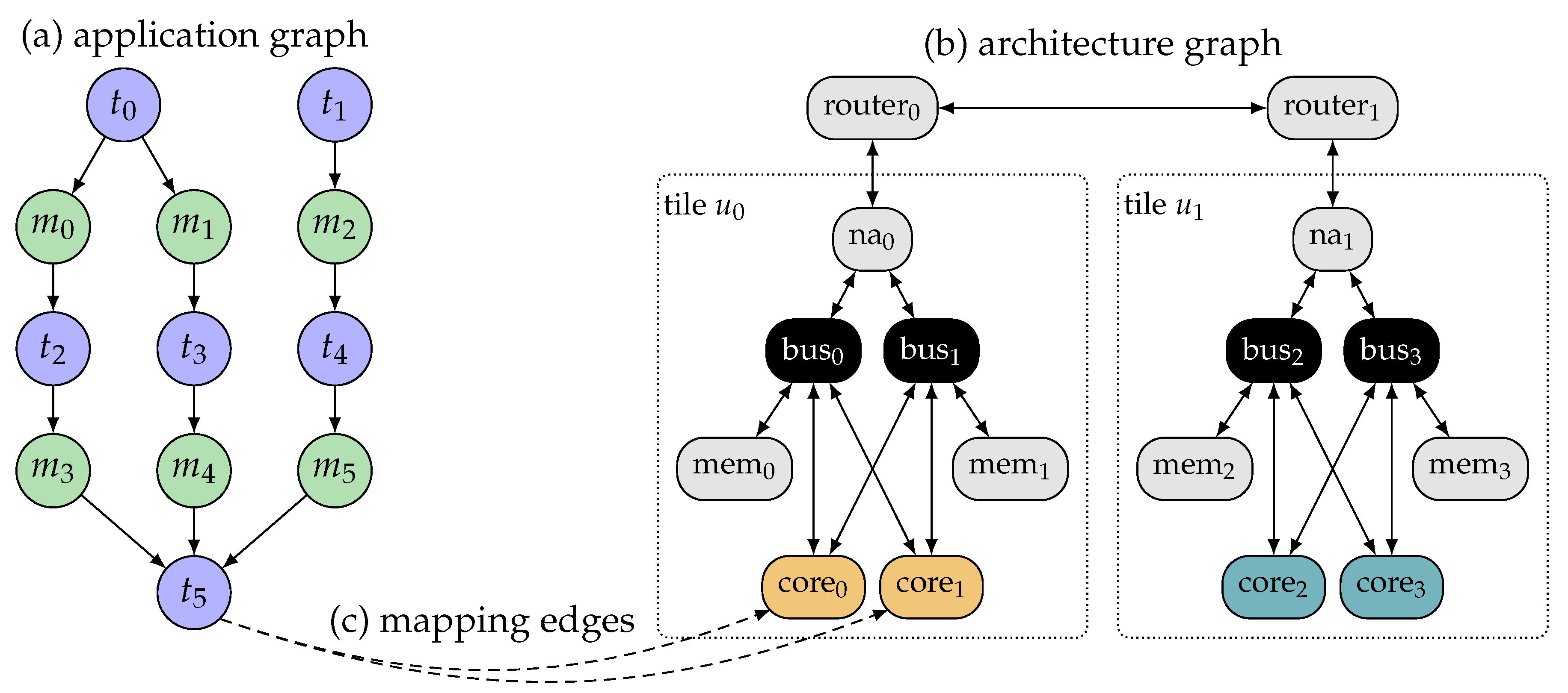
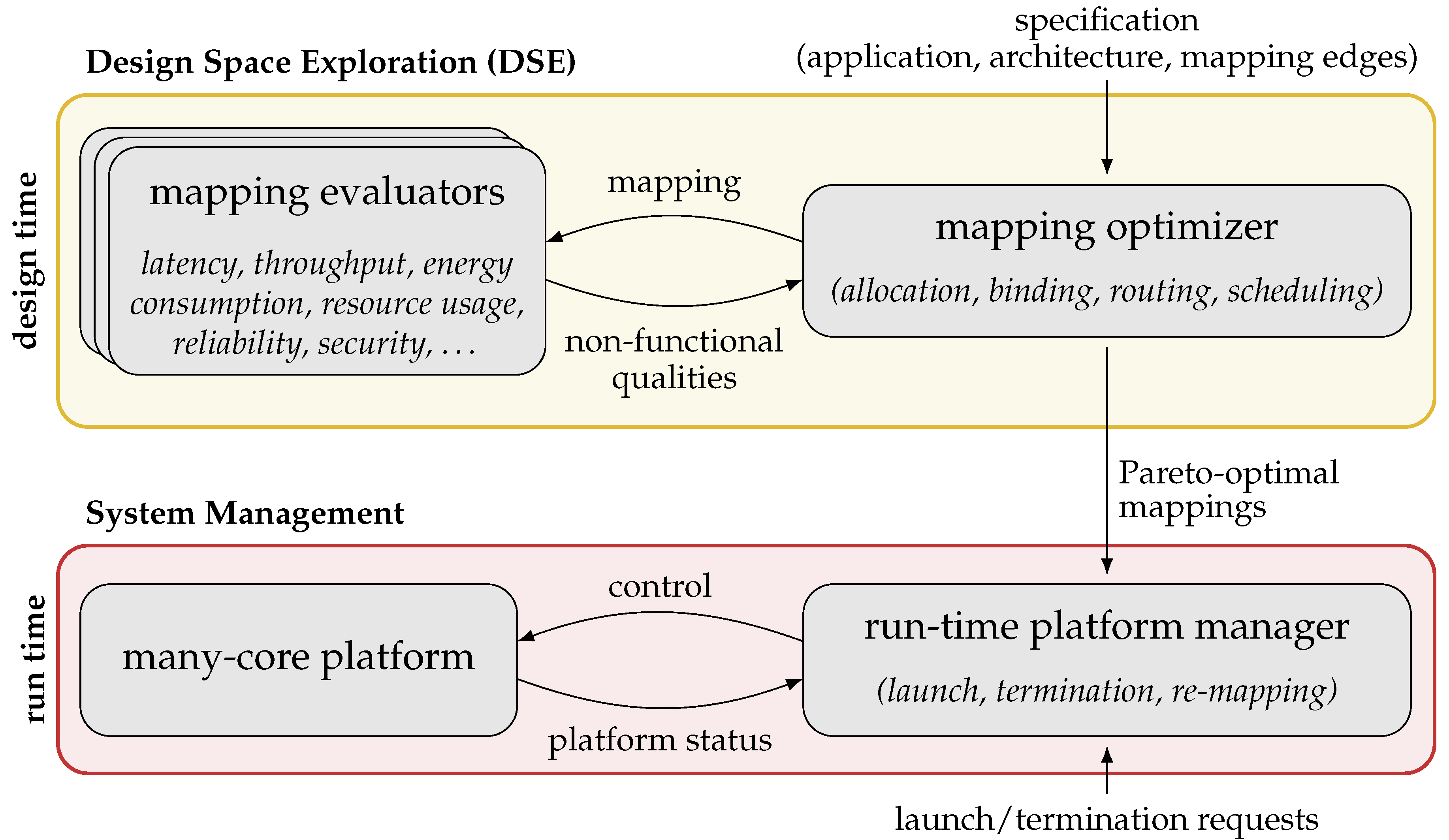
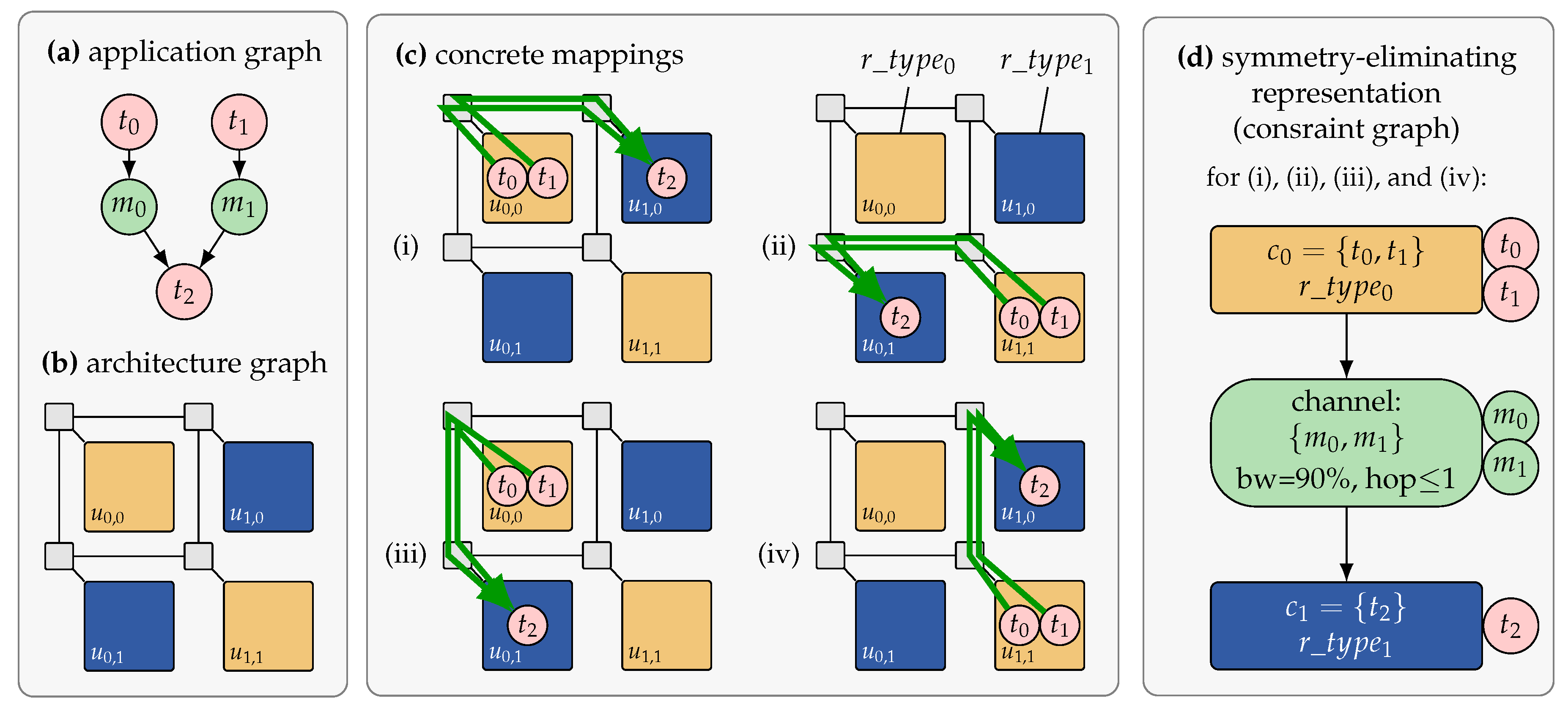
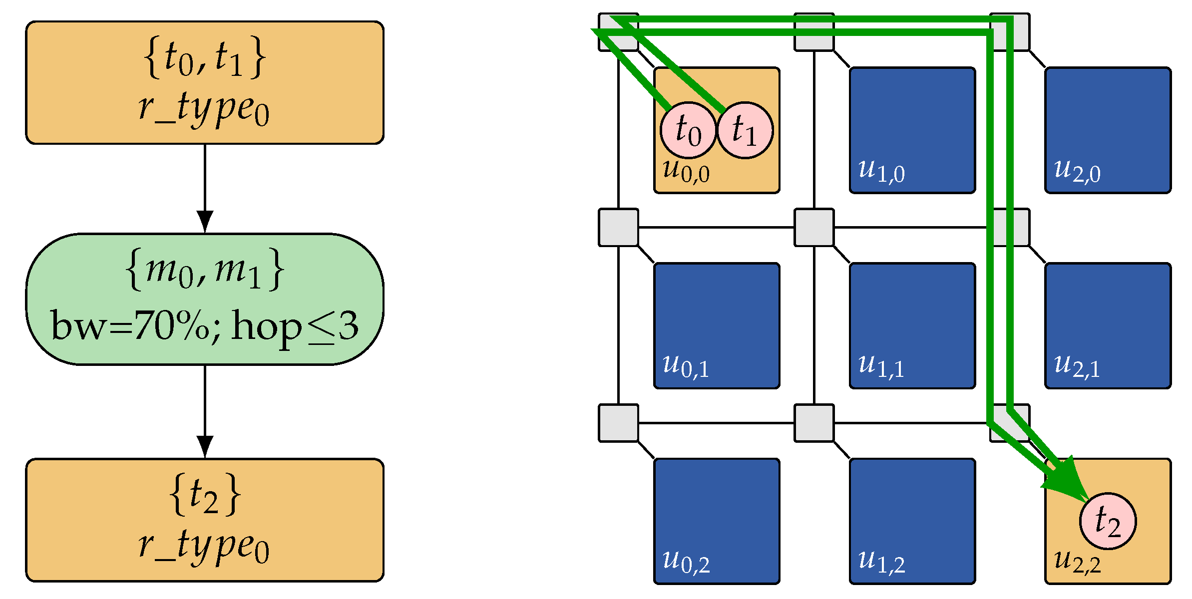
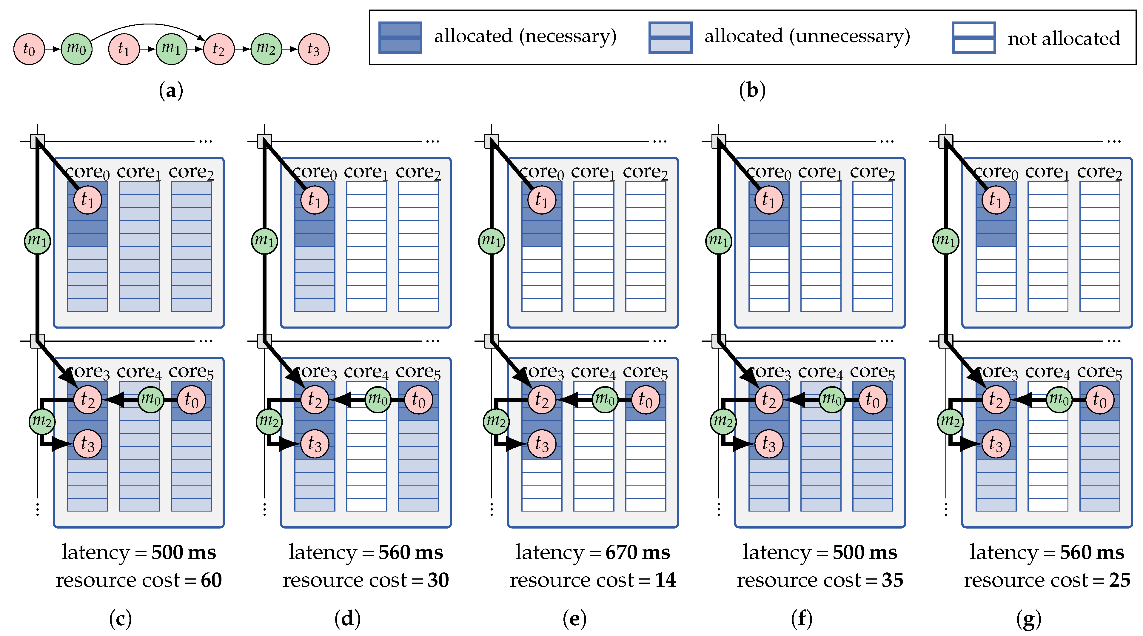
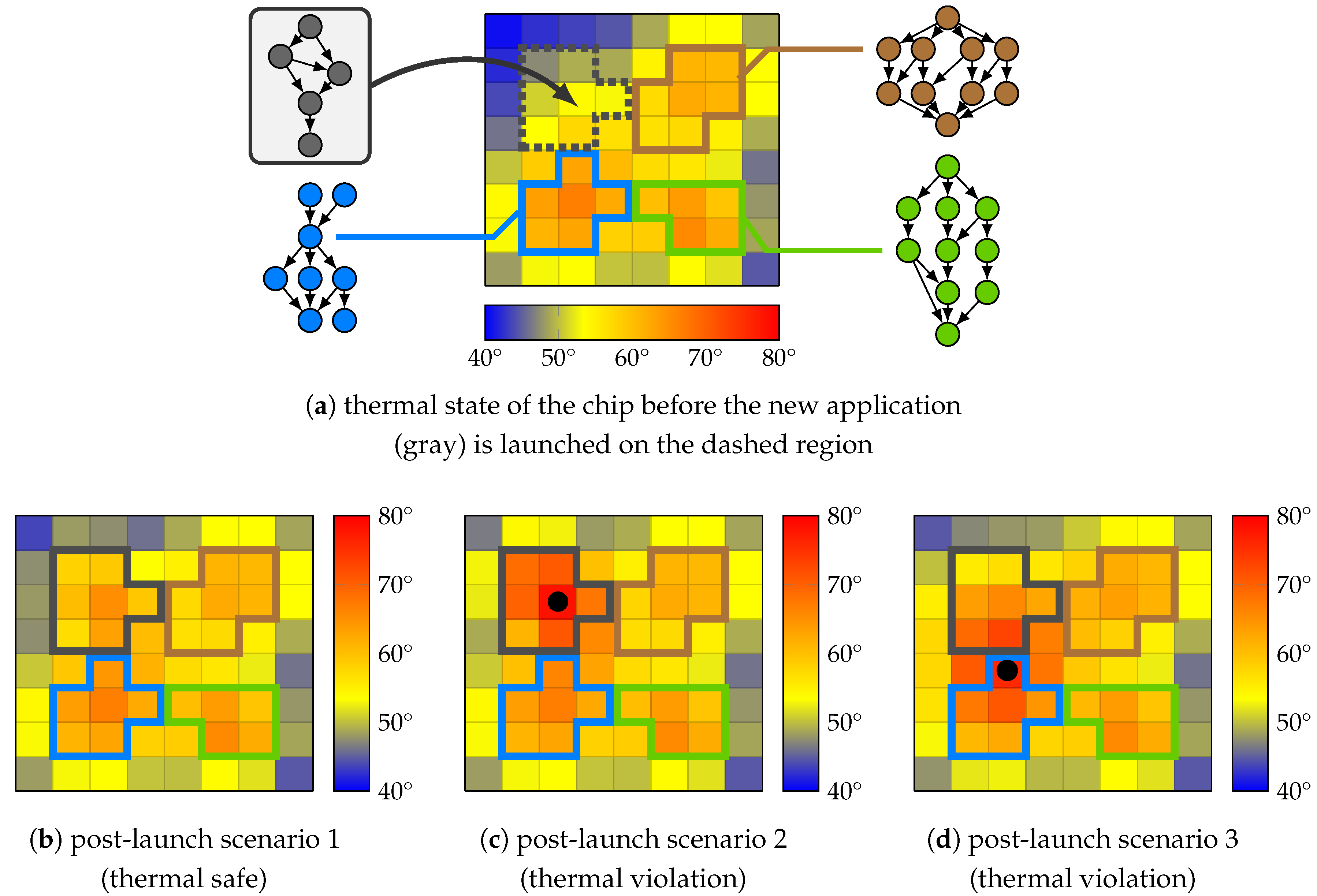
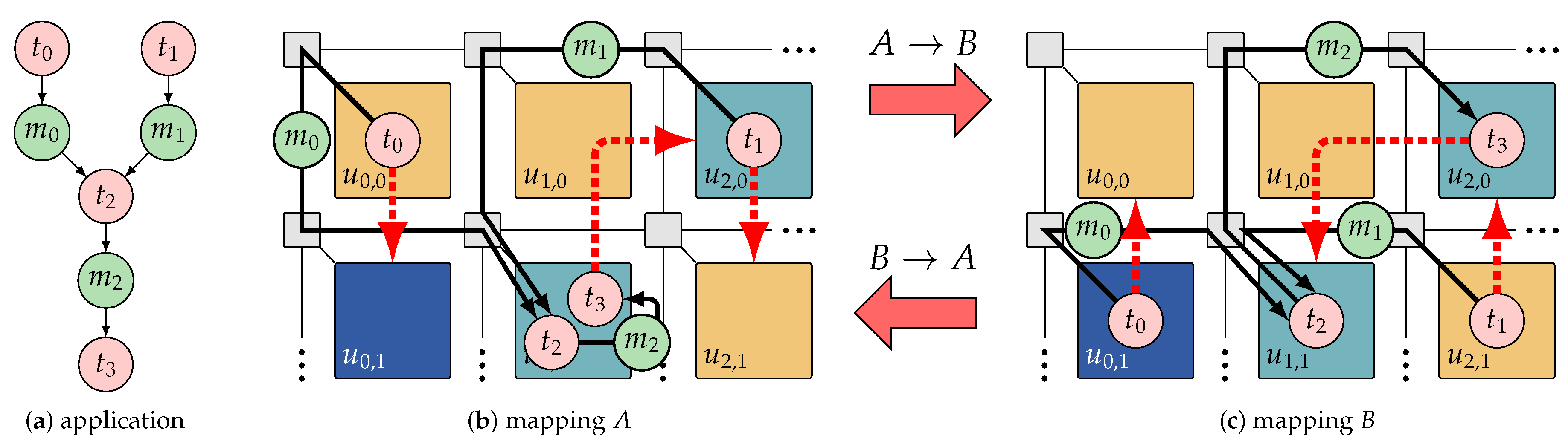
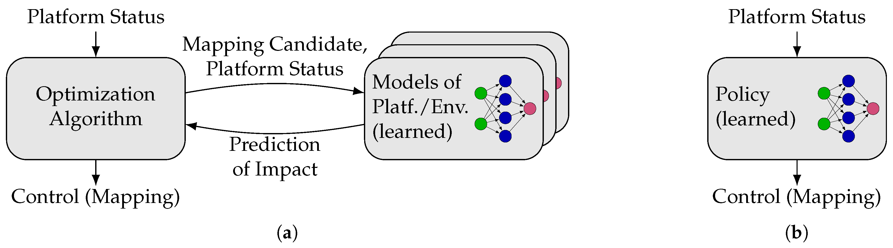
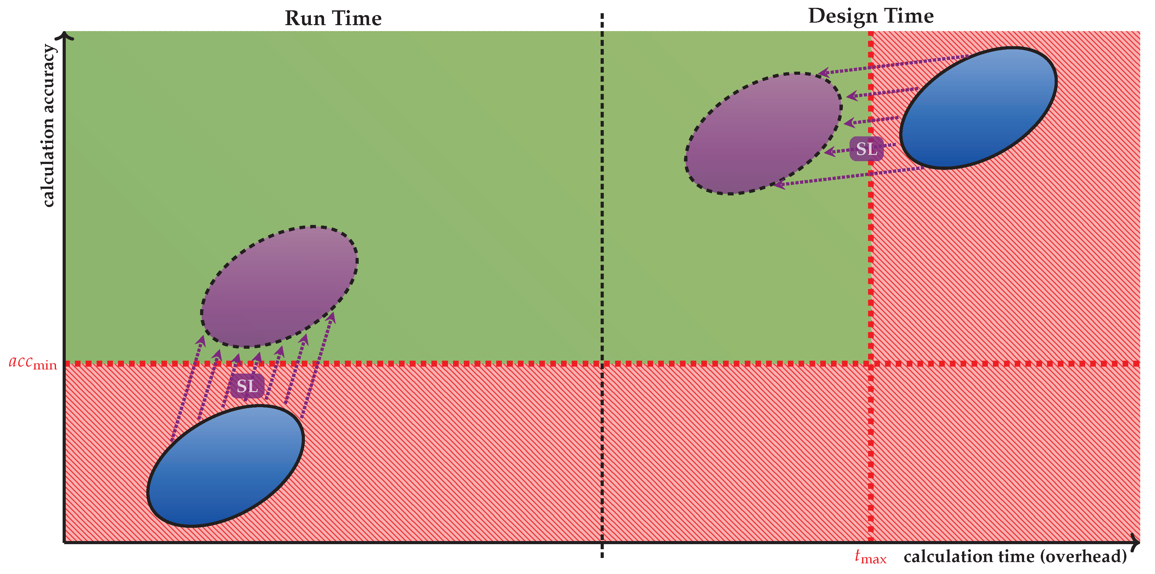


