
LoRaWAN Base Station Improvement for Better Coverage and Capacity


Faculty of Electrical Engineering and Computing, University of Zagreb, Unska 3, HR-10000 Zagreb, Croatia
*
Author to whom correspondence should be addressed.
J. Low Power Electron. Appl. 2022, 12(1), 1; https://0-doi-org.brum.beds.ac.uk/10.3390/jlpea12010001
Submission received: 22 November 2021
/
Revised: 27 December 2021
/
Accepted: 28 December 2021
/
Published: 30 December 2021
(This article belongs to the Special Issue Advanced Researches in Embedded Systems)
Abstract
:Low Power Wide Area Network (LPWAN) technologies provide long-range and low power consumption for many battery-powered devices used in Internet of Things (IoT). One of the most utilized LPWAN technologies is LoRaWAN (Long Range WAN) with over 700 million connections expected by the year 2023. LoraWAN base stations need to ensure stable and energy-efficient communication without unnecessary repetitions with sufficient range coverage and good capacity. To meet these requirements, a simple and efficient upgrade in the design of LoRaWAN base station is proposed, based on using two or more concentrators. The development steps are outlined in this paper and the evaluation of the enhanced base station is done with a series of measurements conducted in Zagreb, Croatia. Through these measurements we compared received messages and communication parameters on novel and standard base stations. The results showed a significant increase in the probability of successful reception of messages on the novel base station which corresponds to the increase of base station capacity and can be very beneficial for the energy consumption of most LoRaWAN end devices.
1. Introduction
In order to develop the Internet of Things (IoT), a network of devices that communicate with each other and other systems over the Internet, it is necessary to have communication technology that provides long-range and low power consumption. Technologies in which high data rate is traded for wide coverage and energy efficiency are known as Low Power Wide Area Networks (LPWAN). According to [1], over 90% of all connected devices use one of four most utilized LPWAN technologies: NB-IoT (Narrowband IoT), LoRaWAN (Long Range WAN), LTE-M (Long Term Evolution for Machines), and Sigfox.
It is considered that LoRaWAN will, along with NB-IoT connect 86% of all LPWAN devices by the year 2023 [2]. The key difference between the two is linked to the frequency spectrum they use. LoRaWAN operates in unlicensed spectrum and can provide lower prices in terms of devices and services. On the other hand, since the spectrum it uses is shared with other technologies, interference problems with other systems are possible. To reduce it, LoRaWAN use Chirp Spread Spectrum (CSS) [3] modulation technology in which data is encoded with frequency-modulated signal—chirp, which enhances long-range communication and robustness to interference.
Another advantage of LoRaWAN over other LPWAN technologies is its big community which can be seen through a number of published research and experimental evaluations. For instance in [4], results of field experiments in Paris with performance evaluation and network coverage are given. In [5], LoRaWAN testbeds are made for the comparison of indoor and outdoor measurements with the results of LoRaSim simulation implemented and described in [6].
Further evaluations focused on different environments and Authors in [7,8,9,10,11,12,13] conducted analysis and experiments for urban and suburban areas, while in [14,15] maritime and mountain areas were analyzed, respectively. In particular, in [7,9] urban scenarios were thoroughly tested showing reasonable coverage with simple base stations highlighting the height of the base stations and topology as major factors affecting the deployment strategy. This conclusion was also confirmed in [10] who included indoor coverage in their measurements. In addition, in [13], urban, suburban and rural, stationary and mobile scenarios were considered, indicating that propagating conditions in the deployment scenario need to be carefully evaluated before actual implementation. As observed in these related works, network coverage and capacity in different terrains and for different configurations are generally acceptable, however, the network implementation should be done carefully to maximize the LoRaWAN potential. Additionally, as pointed out in [16,17] in which different real-life tests of the LoRaWAN network were conducted, on average there was around 30% of packet loss, indicating that there is significant room for improvement. There were also various research activities regarding coverage enhancement, but their focus was either on end node improvement [18,19] or constructing multi-hop network [20,21], while the base station enhancements were generally not considered.
The problem of packet loss and efficiency is not critical in situations where there are just a few sensors, however, it becomes an issue in more complex applications. For example, in applications where there are many sensors in a small area, there is large probability of message collisions and consequently packet loss, which will result in the need for unnecessary message retransmission. Also, it can be an issue in remote areas where battery efficiency is critical and frequent retransmissions could significantly reduce the lifetime of the node. In these scenarios we need to improve the reception of the base station and we propose a simple and cost-effective upgrade of the LoRaWAN base station using additional concentrators. This enables more flexibility for the user, improved capacity, and consequently has a significant indirect impact on energy efficiency since low power end nodes will potentially require fewer repetitions to send their messages thus saving power. Also, by using a dual or multiple concentrator setup, a wide range of customizations for specific applications are possible. For example, it can be beneficial to create sectors with directional antennas and dedicated concentrators to separate and improve reception in certain directions. This simple enhancement of the base station requires little resources, but it can be a very valuable tool in extending and improving the range and capacity of the network alongside the end node improvements, deployment scenario considerations and similar.
Within this paper, we present the idea and the development of the LoRAWAN system with an upgraded dual-concentrator base station. To evaluate the system and confirm the improvements, a series of measurements were taken in the city of Zagreb, Croatia using a reference single-concentrator base station and the upgraded one. Both base stations were positioned in the same location and the results confirmed the enhancement in the properties of the overall system.
The paper is organized in the following way: in Section 2 a short overview of LoRaWAN is given providing basic terms needed to understand the problem this paper deals with. In Section 3 the novel design of the base station is presented and in Section 4 the results of the measurements and validation are shown.
2. Overview of LoRaWAN
Overview of LoRaWAN technology is given in this section for completeness. LoRaWAN is the most utilized LPWAN technology that operates in unlicensed spectrum with 151 network operators in 167 countries in 2021 according to [22]. The modulation technology used in the physical layer of LoRaWAN is patented [23] by Semtech Corporation, but to reach wider community, it is licensed to other commercial companies which produce radio modules.
To keep the network complexity and power consumption low, LoRaWAN uses star topology where end devices communicate directly with base stations using LoRaWAN protocol on different channels and with variable data rates. End devices do not connect to a specific base station but send their data to all nearby base stations that forward it via TCP/IP protocol to a network server. Network server is the main part of LoRaWAN network as it manages join requests and device addressing, data delivery to and from a user application, duplicate frame filtering, adapting data rate and security functions. The last component of the architecture is an application server that communicates with the network server over TCP/IP, decodes the received data and initiates messages towards end devices.
Before sending any data, the end device has to be activated using either Over-The-Air Activation (OTAA) or Activation By Personalization (ABP) method. The main difference between the two options is in generating the device identifier (DevAddr) and the session keys in the network: in ABP activation they are hardcoded in the device while in OTAA they are assigned at the start of the connection (in Join Request/Join Response phase). Session keys are used in Advanced Encryption Standard (AES) [24] to provide secure end-to-end communication. More detailed research regarding security in LoRaWAN can be found in [25,26].
In order to retain low power consumption while providing bi-directional communication, LoRaWAN is based on a simple ALOHA protocol with three defined end device classes: A, B and C. Class A is the basic one and is designed for ultra low power end devices enabling only two short receive windows for downlink transmission (from base station to end device) after a packet is sent. In class B, on top of class A, there is one more receive window open in the scheduled interval while class C devices are able to receive all the time when they are not transmitting providing lowest downlink latency [27]. On the other hand, as shown in [28], class A devices require lowest, while class C devices require highest power consumption.
Compared to LPWAN technologies that operate in licensed spectrums, LoraWAN has lower data rate and payload size. Specifically, LoRaWAN can send a maximum of 256 B of payload with data rate of 27 kbps [27] while in NB-IoT maximum payload size is 1600B which can be transmitted with data rate of 250 kbps [29]. However, this is balanced by the fact that LoRaWAN devices are more energy efficient [30] and affordable [31]. In LoRaWAN, bandwidth (BW) can be 125, 250 or 500 kHz, where higher bandwidth corresponds with higher data rate, but also with lower sensitivity. Generally, all mentioned LPWAN technologies provide 2–5 km range in urban and over 10 km in rural areas and, with transmission power limited to around 25 mW, low energy consumption with device’s battery life of 10 years [32].
Spreading Factor
As mentioned, LoRaWAN uses CSS technology to cope with interference and to provide long-range. CSS is a modulation method where frequency modulated signals, also known as chirps, are used to encode the data. Chirp with increasing frequency is called upchirp, and with decreasing frequency is called downchirp. On the physical layer, one LoRa packet consists of:
- 8 upchirps for preamble,
- 2.25 downchirps for synchronization symbols, and
- “choppy” upchirps for physical payload.
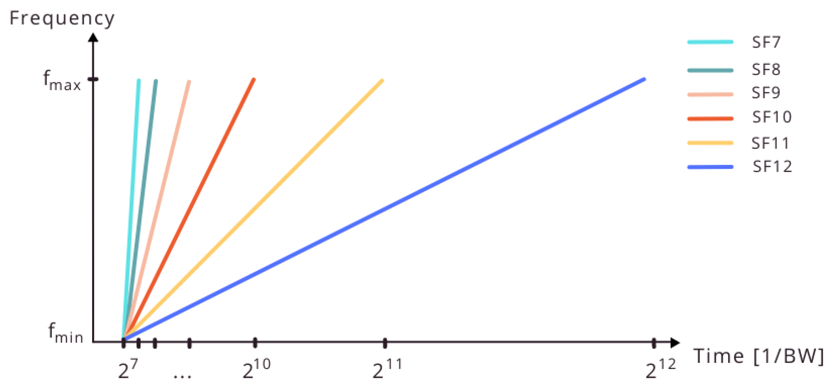
Each of the “choppy” upchirps starts with frequency between and (BW = −) that are minimum and maximum frequencies of CSS and define input information. Number of bits in the input information and chirp’s length are dependent on a spreading factor (SF) which represents number of bits per symbol (one symbol has SF bits) and number of chips per symbol (there are chips in one symbol) and can be any number between 7 and 12. The correlation between spreading factor and symbol duration is given in Figure 1. Since the chip duration is equal to 1/BW, symbol duration with chips is /BW. Therefore, the symbol rate is BW/ which leads to the data rate:
where CR is the code rate.
Lower spreading factor increases the data rate but decreases range and vice versa. For example, in conditions with constant bandwidth, when the distance between end device and base station is challenging, the use of spreading factor 12 is suggested to enable communication. In the opposite situation, when the distance between them is short, higher data rate is possible using spreading factor 7. Adapting the spreading factor and bandwidth to conditions in the communication channel is one of LoRaWAN advantages. Network server adapts the parameters based on the value of SNR (Signal to Noise Ratio) to provide the best data rate in the given situation. This feature is called Adaptive Data Rate (ADR).
Spreading factor also has an impact on Time on Air (ToA) defined as elapsed time for a LoRaWAN packet to transmit between end device and base station. It is given with:
where is the number of symbols in preamble, the number of symbols in data and the aforementioned symbol duration (/BW). Since LoRaWAN operates in unlicensed spectrum, its devices have duty cycle limitation which means that there is a maximum percentage of time during which a device can occupy a channel. Exact time a device has to wait after sending a message can be calculated for each subband using ToA:
Duty cycles are usually regulated by governments and are dependent on subband [27].
3. Design of LoRaWAN Base Station
3.1. Standard LoRaWAN Base Station
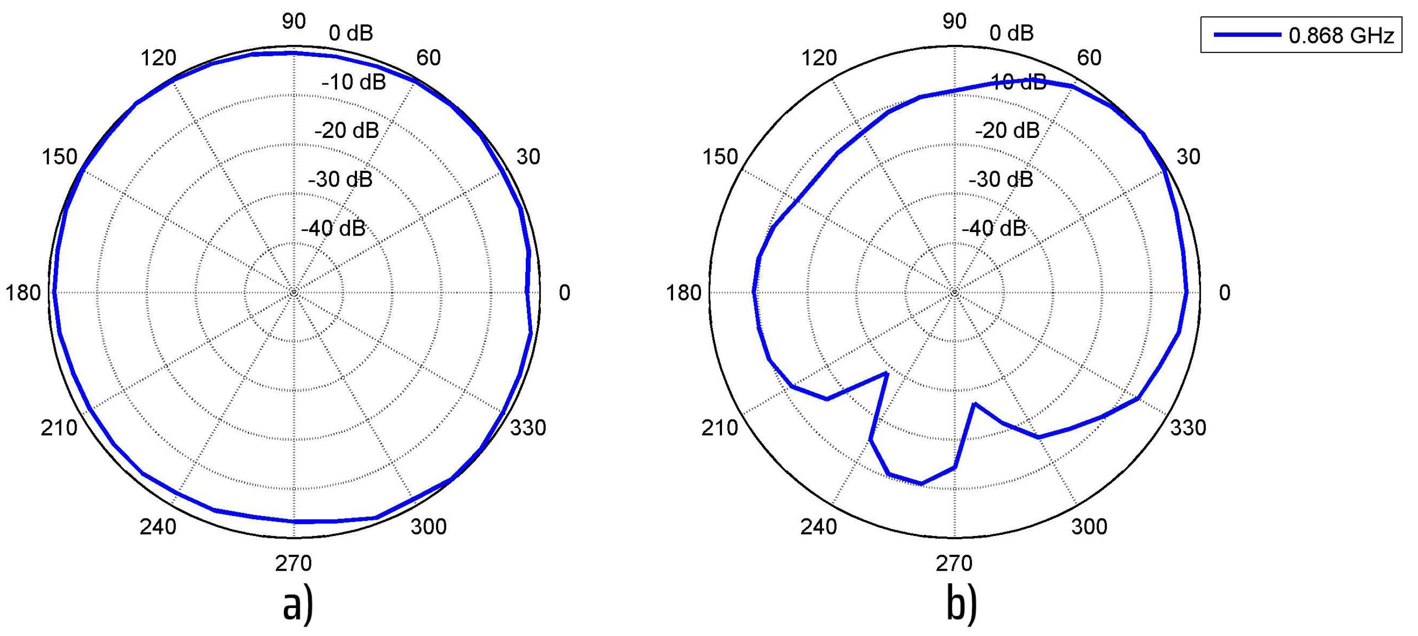
The implementation of the LoRaWAN base station is based on [33] where a Raspberry Pi is used as a microcomputer and certified LoRaWAN board iC880A [34] as a concentrator. Raspberry Pi 4B is high-performance microcomputer with large support community, while iC880A concentrator is able to receive messages sent with different spreading factors on up to 8 channels in parallel. In the model, an omnidirectional antenna [35] with a frequency range between 824 and 896 MHz (for EU868 region) is connected to the concentrator, and concentrator to the microcomputer using Serial Peripheral Interface (SPI). The developed base station is registered to The Things Network (TTN) Server [36]. The radiation pattern of the omnidirectional antenna used in standard single antenna base station is given in Figure 2a).
3.2. Proposed Improvement for LoRaWAN Base Station
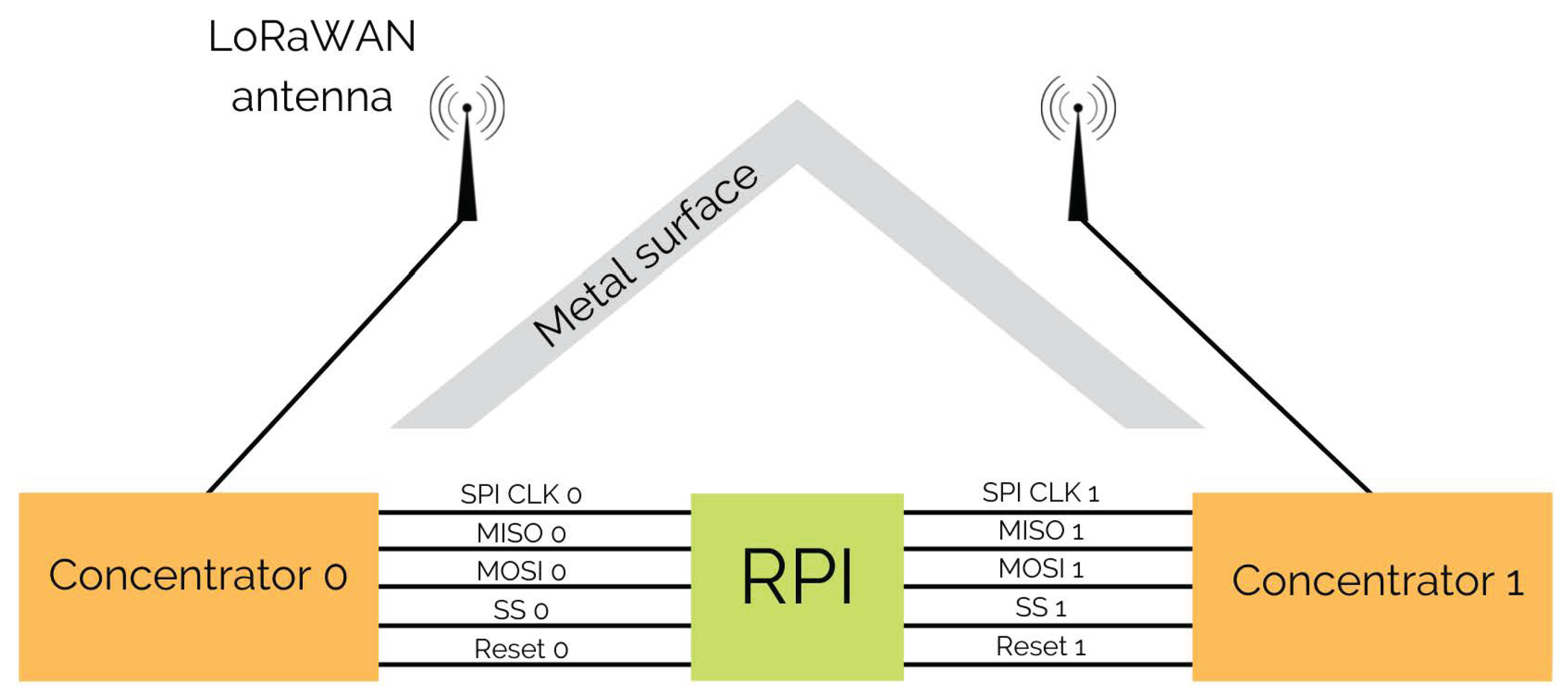
To improve reception, capacity and to provide added flexibility in the spatial coverage an upgrade of the existing base station design is proposed. This is achieved using an additional (second) concentrator and a prototype is built also using Raspberry Pi microcomputer. Both concentrators are connected with the Raspberry Pi via predefined SPI connections SPI0 and SPI1:
- SPI clock,
- Master in slave out (MISO),
- Master out slave in (MOSI), and
- Slave select (SS).
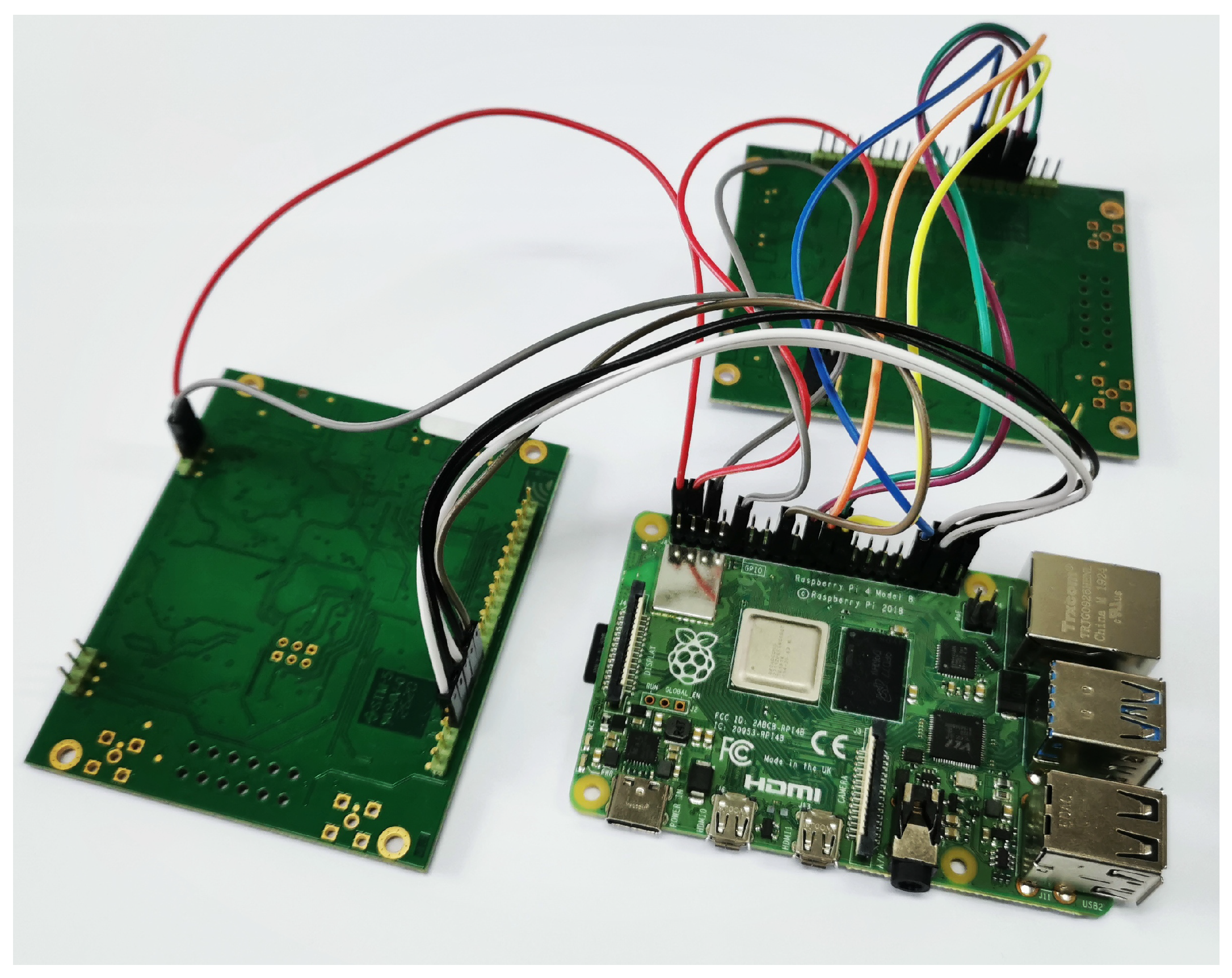
Raspberry Pi and concentrators used in the measurements are shown in Figure 3. Pins on concentrators and Raspberry Pi used in SPI connections are defined by the manufacturer. Along with SPI connections, each concentrator has its own Reset signal connection which is used to start the initialization process of that concentrator. Reset pin on the Raspberry Pi can be any GPIO (General-Purpose Input/Output) pin. Detailed pinout of the system is given in Table 1. The implemented program initializes each concentrator, connects them as two gateways to TTN and for each of them runs packet forwarder. Defining two gateways on TTN is important so that communication on each concentrator can be tracked and analyzed separately. As mentioned, this paper focuses on base station model with two concentrators since it is the simplest case. However, the same principle can be used for base stations with more than two concentrators to provide more flexibility.
Apart from improving the capacity, two concentrators and primarily their antennas can be positioned in a way to best suit certain application. The example shown in Figure 4 positions the antennas next to the metallic edge (emulating a large pillar or edge of the building) to demonstrate one possibility. This is beneficial in dense sensor environments (Smart city case) where often due to congestion some messages can be lost.
Two SPI connections enable two sets of concentrator and antenna to work in parallel without interrupting each other. The challenge of such a setup is that messages received from both concentrators are sent towards Network Server and that causes duplicates. This can be solved by adding a filtering function before forwarding packets to the network. However, since Network Server already filters duplicates for each application there is no need for that.
Second concentrator/antenna set enhances network capacity and network coverage in the wanted direction when combined with metal surface that provides sector-shaped radiation pattern. Metal surface behind each antenna was 30 cm high and 50 cm wide. The antenna is set 8.6 cm away from the metal surface which is approximately in LoRaWAN frequency range (868 MHz) to ensure that antenna remains well matched. Obtained radiation pattern for this setup for one of the antennas is shown in Figure 2b).
4. Results
4.1. Measurement Setup
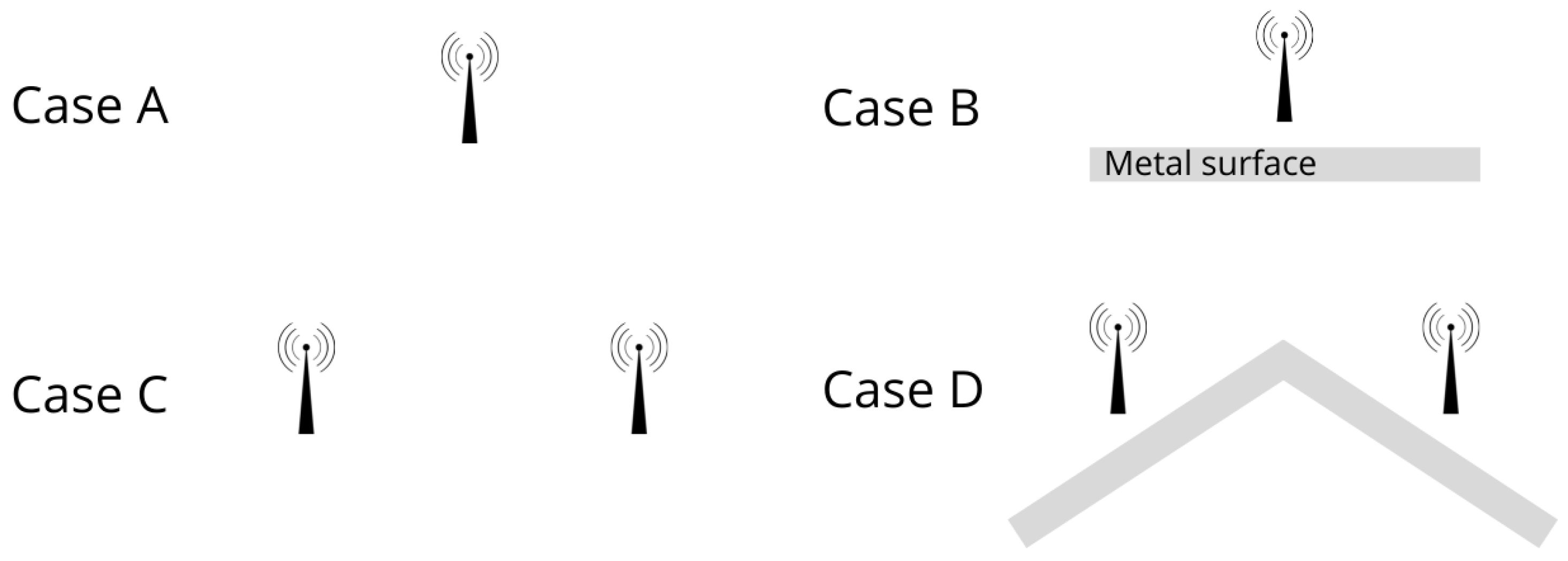
The aim of the measurements was to evaluate the proposed dual setup in a real-world LoRaWAN communication scenario. Two LoRaWAN base stations were implemented: one using existing code [33] based on Raspberry Pi (case A in Figure 5) with one concentrator and antenna, and the other using customized code running on second Raspberry Pi with two sets of concentrators and antennas connected via two predefined SPI connections according to Figure 4.
The base stations are set on the top of the 60 m high building of the Faculty of Electrical Engineering and Computing, University of Zagreb, Croatia. There were two rounds of measurements. The first was conducted without metal surface behind antennas of the novel base station (case C), and for the second one the metal surface was added (case D). Since the base stations are registered to TTN, all messages sent from devices in the vicinity of the building are received. In both cases base stations worked for five hours.
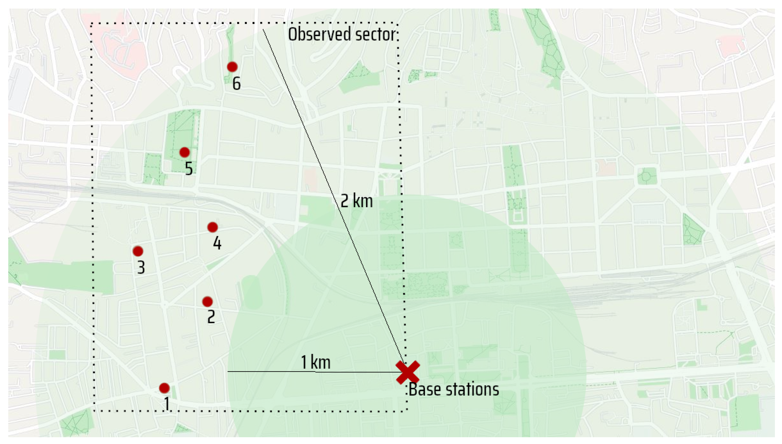
In order to test the impact of metal surface on received signal strength indicator (RSSI) for each spreading factor, we developed a dedicated LoRaWAN end device. Pycom board [37] was programmed to send LoRaWAN messages with different spreading factors using LoRa radio module on LoPy board [38]. The antenna connected to the board was the same as those used on the base stations [35]. The end device sent messages from six locations in the dense urban area of Zagreb, Croatia approximately 1–2 km away from the building with the base stations.
4.2. Prototype Validation
The analysis of messages obtained from the measurements showed that even without the metal surface behind the antennas, the novel base station with two concentrators received more messages than the single base station. Specifically, in the same period of time (in 5 h), base station with two antennas without metal surface (case C) received 98.7% of all messages that base stations received combined. On the other hand, base station with one antenna received 76% of those messages which means that the second set of concentrator and antenna increased the probability of successful transmission. This is a very valuable improvement since it is important for energy efficiency of the entire network as LPWAN networks in most cases work with battery-powered devices.
When the metal surface was added (case D), number of messages received on both base stations increased by 25% (from 2235 to 2797 messages). As expected this increase shows that adding the metal surface improved base station directivity and thus also the range. The percentage of the messages received on the novel base station remained the same as in the first case but that percentage decreased for the standard single antenna base station (67%) which indicates that the novel base station received more messages with the metal surface set behind the antennas. Table 2 shows the percentage of received messages on each base station.
For the second part of novel base station model validation we used the aforementioned LoRaWAN end node to test the improvement when the metal surface is set behind the antenna. For comparison, we set the metal surface behind the antenna of one base station (case B) while the other was the standard one (case A). All components used in the development of both base stations were the same. The end node was programmed to send six messages with different spreading factors. Bandwidth was set to be 125 kHz and payload size 3 B so that communication parameters only depend on spreading factor and distance from the base stations. The end device sent 12 messages (two series of six messages (for SF7 to SF12)) from each of 6 locations set approximately 1–2 km away from the building with the base stations in the dense urban area of Zagreb, Croatia. Since the focus was to evaluate the impact of metal surface for sector radiation purposes, all end device locations were set in the same sector as shown in Figure 6.
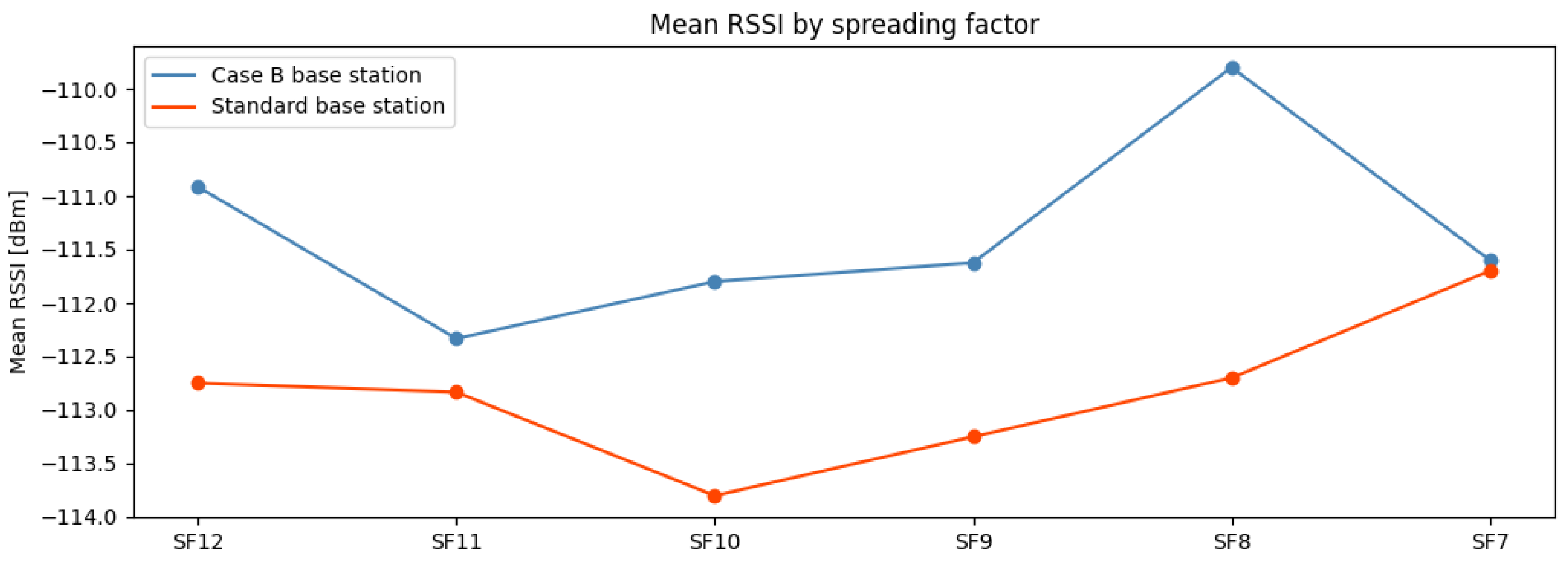
The results showed that base stations received 86% of the messages (31 of 36) sent by end device. In 80% of them (25 of 31) the base station with metal surface behind the antenna received with higher RSSI than the standard one. In some cases, the difference between RSSIs was 9 dB which could be significant for extended range. Regarding spreading factor, as shown in Figure 7, mean RSSI is higher for each spreading factor on base station with directed antenna (with metal surface behind the antenna). The biggest difference can be seen for SF8 where the increase of mean RSSI is around 3 dB while the smallest one is for messages sent with SF7.
In order to evaluate RSSI for different spreading factors while keeping the distance between base stations and end device relatively short (urban environment), ADR had to be disabled (otherwise the ADR algorithm would always use SF7 or SF8) and spreading factor set manually for each LoRaWAN message.
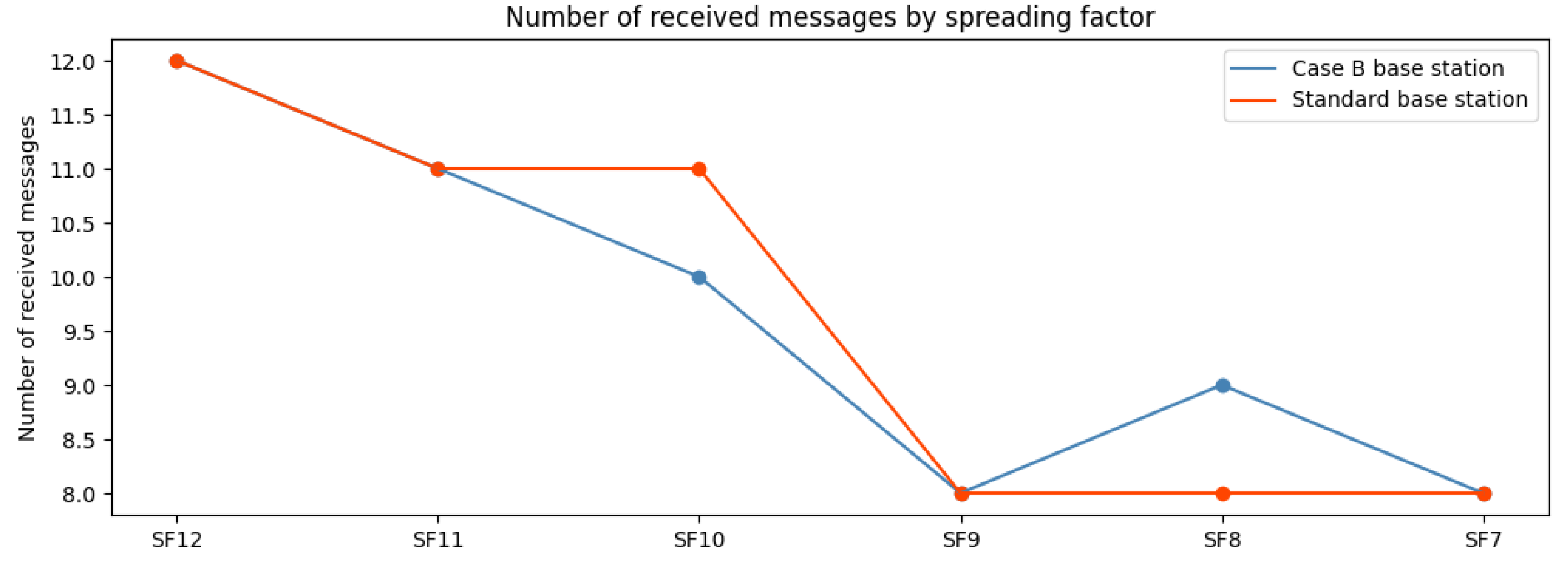
According to Figure 8, the number of received messages by spreading factor is similar on both base stations. The only difference is that the novel base station received one message more with SF8 and standard one with SF10. All 12 messages sent with SF12 were successfully transmitted, while messages with lower spreading factor, for instance SF7, were received in 8 of 12 cases by both of them. Since number of messages sent from each location with test end device is relatively low, this kind of behavior where novel base station receives similar number of messages by spreading factor as standard one is expected.
It is important to emphasize that prior to any measurements all the components used were tested to determine any differences between them or potential problems. In particular, all passive components, antennas, connectors and cables, were tested since we had to choose the ones with the same losses in order not to influence the RSSI measurements. Also, the active components, concentrators and Raspberry Pi-s were switched between configurations in multiple iterations of the measurements to eliminate the possibility of technical problems and any differences in signal reception. Since the measurements were done in the urban environment it was also important to perform the repeated measurement from exactly the same locations and positions since even small deviations in position could result in significant reception differences due to propagation differences.
5. Conclusions
LoRaWAN networks have great potential for the development of new applications and systems. To improve the capacity of standard base stations, add flexibility, and potentially extend the lifetime of end nodes in the network, we designed and demonstrated an upgraded low-cost base station. The upgrade is based on adding a second set of concentrator and antenna, which is practically demonstrated using a low-cost base station design based on microcomputer Raspberry Pi, concentrators iC880A and additional software modifications. This upgrade allows also more flexibility in the positioning of the antennas leading to potentially extended range in certain directions or similar application scenarios. Increased capacity and potentially improved coverage or range can both be very beneficial for the operation of the sensor nodes since these improvements lead to a more successful reception and fewer message repetitions.
To validate the improvements, two base stations were developed; standard one based on the aforementioned design, and novel dual-concentrator based one. In the first evaluation, a comparison of the number of messages received on them was performed for the real-world communication case and showed that dual-concentrator setup increased the probability of successful reception on the novel base station. This improvement can be very beneficial for the energy consumption of most LoRaWAN end devices or sensor nodes since they are usually battery-powered. Additionally, when metal surface was added behind the antennas of novel base station, the number of received messages increased by 25% which indicated that network coverage can also be easily extended.
The comparison between communication parameters of the received messages also confirmed the improvement of the proposed base station when used in combination with a metal reflector. Communication between test end node and base stations in the dense urban area showed that messages were received with higher signal strength on the novel base station than on the standard one. The analysis showed that mean RSSI received for messages sent from different locations in 1–2 km range is higher in all spreading factor cases on the novel base station.
The presented idea of low-cost base station upgrade and its validation demonstrated its feasibility, and it is a proof of concept for improvement of base station coverage and capacity in LoRaWAN. The setup will be further extended to multiple concentrators leading to potentially novel applications and additional further evaluations with multiple end nodes will be conducted to reveal the actual savings in terms of battery power.
Author Contributions
Conceptualization, F.T. and G.Š.; methodology, M.B.; software, F.T.; validation, F.T., G.Š. and M.B.; formal analysis, F.T.; investigation, F.T. and M.B.; resources, G.Š.; data curation, F.T.; writing—original draft preparation, F.T.; writing—review and editing, F.T., G.Š. and M.B.; visualization, F.T.; supervision, G.Š. and M.B.; project administration, G.Š. and M.B.; funding acquisition, M.B. All authors have read and agreed to the published version of the manuscript.
Funding
This work was supported in part by Croatian Science Foundation (HRZZ) under the project number IP-2019-04-1064.
Institutional Review Board Statement
Not applicable.
Informed Consent Statement
Not applicable.
Data Availability Statement
https://github.com/filt27/Two-Antenna-LoRaWAN-GW, accessed on 29 December 2021.
Conflicts of Interest
The authors declare no conflict of interest.
References
- IoT Analytics. LPWAN Market Report 2020–2025. 2020. Available online: https://iot-analytics.com/product/lpwan-market-report-2020-2025/ (accessed on 21 May 2021).
- Ratliff, L. Unlocking Captive Value—LPWAN Enables Emerging IoT Applications. Available online: https://lora-alliance.org/wp-content/uploads/2020/11/ihsmarkit_berlin_2019_0.pdf (accessed on 11 October 2021).
- Reynders, B.; Pollin, S. Chirp spread spectrum as a modulation technique for long range communication. In Proceedings of the 2016 Symposium on Communications and Vehicular Technologies (SCVT), Mons, Belgium, 22 November 2016; pp. 1–5. [Google Scholar] [CrossRef]
- Augustin, A.; Yi, J.; Clausen, T.; Townsley, W.M. A Study of LoRa: Long Range Low Power Networks for the Internet of Things. Sensors 2016, 16, 1466. [Google Scholar] [CrossRef] [PubMed]
- Marais, J.M.; Malekian, R.; Abu-Mahfouz, A.M. LoRa and LoRaWAN testbeds: A review. In Proceedings of the 2017 IEEE AFRICON, Cape Town, South Africa, 18–20 September 2017; pp. 1496–1501. [Google Scholar] [CrossRef]
- Bor, M.C.; Roedig, U.; Voigt, T.; Alonso, J.M. Do LoRa Low-Power Wide-Area Networks Scale? In Proceedings of the 19th ACM International Conference on Modeling, Analysis and Simulation of Wireless and Mobile Systems, Valletta, Malta, 13–17 November 2016; Association for Computing Machinery: New York, NY, USA, 2016; pp. 59–67. [Google Scholar] [CrossRef] [Green Version]
- Petrić, T.; Goessens, M.; Nuaymi, L.; Toutain, L.; Pelov, A. Measurements, performance and analysis of LoRa FABIAN, a real-world implementation of LPWAN. In Proceedings of the 2016 IEEE 27th Annual International Symposium on Personal, Indoor, and Mobile Radio Communications (PIMRC), Valencia, Spain, 4–8 September 2016; pp. 1–7. [Google Scholar] [CrossRef] [Green Version]
- Turčinović, F.; Vuković, J.; Božo, S.; Šišul, G. Analysis of LoRa Parameters in Real-World Communication. In Proceedings of the 2020 International Symposium ELMAR, Zadar, Croatia, 14–15 September 2020; pp. 87–90. [Google Scholar] [CrossRef]
- Harris, N.; Curry, J. Development and Range Testing of a LoRaWAN System in an Urban Environment. Available online: https://zenodo.org/record/1315517#.Yc0GNSBByMo (accessed on 24 May 2021).
- Wixted, A.J.; Kinnaird, P.; Larijani, H.; Tait, A.; Ahmadinia, A.; Strachan, N. Evaluation of LoRa and LoRaWAN for wireless sensor networks. In Proceedings of the 2016 IEEE SENSORS, Orlando, FL, USA, 30 October–3 November 2016; pp. 1–3. [Google Scholar] [CrossRef]
- Blenn, N.; Kuipers, F. LoRaWAN in the wild: Measurements from the things network. arXiv 2017, arXiv:1706.03086. [Google Scholar]
- Terleev, A.V.; Khalturin, A.A.; Shpenst, V.A. LoRaWAN gateway coverage evaluation for smart city applications. In Proceedings of the 2021 3rd International Youth Conference on Radio Electronics, Electrical and Power Engineering (REEPE), Moscow, Russia, 11–13 March 2021; pp. 1–4. [Google Scholar] [CrossRef]
- Sanchez-Iborra, R.; Sanchez-Gomez, J.; Ballesta-Viñas, J.; Cano, M.D.; Skarmeta, A.F. Performance Evaluation of LoRa Considering Scenario Conditions. Sensors 2018, 18, 772. [Google Scholar] [CrossRef] [PubMed] [Green Version]
- Petajajarvi, J.; Mikhaylov, K.; Roivainen, A.; Hanninen, T.; Pettissalo, M. On the coverage of LPWANs: Range evaluation and channel attenuation model for LoRa technology. In Proceedings of the 2015 14th International Conference on ITS Telecommunications (ITST), Copenhagen, Denmark, 2–4 December 2015; pp. 55–59. [Google Scholar] [CrossRef]
- Iova, O.; Murphy, A.; Picco, G.P.; Ghiro, L.; Molteni, D.; Ossi, F.; Cagnacci, F. LoRa from the city to the mountains: Exploration of hardware and environmental factors. In Proceedings of the 2017 International Conference on Embedded Wireless Systems and Networks, Uppsala, Sweden, 20–22 February 2017. [Google Scholar]
- Seye, M.R.; Gueye, B.; Diallo, M. An evaluation of LoRa coverage in Dakar Peninsula. In Proceedings of the 2017 8th IEEE Annual Information Technology, Electronics and Mobile Communication Conference (IEMCON), Vancouver, BC, Canada, 3–5 October 2017; pp. 478–482. [Google Scholar] [CrossRef]
- Petäjäjärvi, J.; Mikhaylov, K.; Pettissalo, M.; Janhunen, J.; Iinatti, J. Performance of a low-power wide-area network based on LoRa technology: Doppler robustness, scalability, and coverage. Int. J. Distrib. Sens. Netw. 2017, 13, 1550147717699412. [Google Scholar] [CrossRef] [Green Version]
- Sisinni, E.; Ferrari, P.; Fernandes Carvalho, D.; Rinaldi, S.; Marco, P.; Flammini, A.; Depari, A. LoRaWAN Range Extender for Industrial IoT. IEEE Trans. Ind. Inform. 2020, 16, 5607–5616. [Google Scholar] [CrossRef]
- Sisinni, E.; Carvalho, D.F.; Ferrari, P.; Flammini, A.; Silva, D.R.C.; Da Silva, I.M.D. Enhanced flexible LoRaWAN node for industrial IoT. In Proceedings of the 2018 14th IEEE International Workshop on Factory Communication Systems (WFCS), Imperia, Italy, 13–15 June 2018; pp. 1–4. [Google Scholar] [CrossRef]
- Sartori, B.; Thielemans, S.; Bezunartea, M.; Braeken, A.; Steenhaut, K. Enabling RPL multihop communications based on LoRa. In Proceedings of the 2017 IEEE 13th International Conference on Wireless and Mobile Computing, Networking and Communications (WiMob), Rome, Italy, 9–11 October 2017; pp. 1–8. [Google Scholar] [CrossRef]
- Liao, C.H.; Zhu, G.; Kuwabara, D.; Suzuki, M.; Morikawa, H. Multi-Hop LoRa Networks Enabled by Concurrent Transmission. IEEE Access 2017, 5, 21430–21446. [Google Scholar] [CrossRef]
- LoRa Alliance Web Page. Available online: https://lora-alliance.org/ (accessed on 19 May 2021).
- Seller, O.B.; Sornin, N. Low Power Long Range Transmitter. U.S. Patent 9252834B2, 2 February 2016. [Google Scholar]
- Daemen, J.; Rijmen, V. Announcing the Advanced Encryption Standard (AES); National Institute of Standards and Technology: Gaithersburg, MD, USA, 2001. [Google Scholar]
- Butun, I.; Pereira, N.; Gidlund, M. Security Risk Analysis of LoRaWAN and Future Directions. Future Internet 2019, 11, 3. [Google Scholar] [CrossRef] [Green Version]
- Magnusson, O.; Teodorsson, R.; Wennerberg, J.; Knoph, S.A. A Survey on Attacks and Defences on LoRaWAN Gateways. In Decision Support Systems and Industrial IoT in Smart Grid, Factories, and Cities; IGI Global: Hershey, PA, USA, 2021; pp. 19–38. [Google Scholar]
- Adelantado, F.; Vilajosana, X.; Tuset-Peiro, P.; Martinez, B.; Melia-Segui, J.; Watteyne, T. Understanding the Limits of LoRaWAN. IEEE Commun. Mag. 2017, 55, 34–40. [Google Scholar] [CrossRef] [Green Version]
- Cheong, P.S.; Bergs, J.; Hawinkel, C.; Famaey, J. Comparison of LoRaWAN classes and their power consumption. In Proceedings of the 2017 IEEE Symposium on Communications and Vehicular Technology (SCVT), Leuven, Belgium, 14 November 2017. [Google Scholar]
- Wang, Y.E.; Lin, X.; Adhikary, A.; Grovlen, A.; Sui, Y.; Blankenship, Y.; Bergman, J.; Razaghi, H.S. A Primer on 3GPP Narrowband Internet of Things. IEEE Commun. Mag. 2017, 55, 117–123. [Google Scholar] [CrossRef]
- Ikpehai, A.; Adebisi, B.; Rabie, K.M.; Anoh, K.; Ande, R.E.; Hammoudeh, M.; Gacanin, H.; Mbanaso, U.M. Low-Power Wide Area Network Technologies for Internet-of-Things: A Comparative Review. IEEE Internet Things J. 2019, 6, 2225–2240. [Google Scholar] [CrossRef] [Green Version]
- Mekki, K.; Bajic, E.; Chaxel, F.; Meyer, F. Overview of Cellular LPWAN Technologies for IoT Deployment: Sigfox, LoRaWAN, and NB-IoT. In Proceedings of the 2018 IEEE International Conference on Pervasive Computing and Communications Workshops (PerCom Workshops), Athens, Greece, 19–23 March 2018; pp. 197–202. [Google Scholar] [CrossRef]
- Bembe, M.; Abu-Mahfouz, A.; Masonta, M.; Tembisa, N. A Survey on Low-Power Wide Area Networks for IoT Applications. Telecommun. Syst. 2019, 71, 249–274. [Google Scholar] [CrossRef]
- The Things Network: iC880a-Based Gateway. Available online: https://github.com/ttn-zh/ic880a-gateway/ (accessed on 20 May 2021).
- iC880A-SPI LoRa® Concentrator. Available online: https://wireless-solutions.de/products/lora-solutions-by-imst/radio-modules/ic880a-spi/ (accessed on 21 May 2021).
- 868 MHz Antenna. Available online: https://shop.imst.de/wireless-modules/accessories/19/sma-antenna-for-ic880a-spi-wsa01-im880b-and-lite-gateway?number=404811 (accessed on 21 May 2021).
- The Things Network. Available online: https://www.thethingsnetwork.org/ (accessed on 24 May 2021).
- Expansion Board. Available online: https://pycom.io/product/expansion-board-3-0/ (accessed on 24 May 2021).
- LoPy module. Available online: https://pycom.io/product/lopy4/ (accessed on 24 May 2021).
Figure 1.
Correlation of LoRa spreading factor and symbol duration is given with /BW. Using higher spreading factor means longer symbol duration which provides better transmission, but decreases data rate.
Figure 1.
Correlation of LoRa spreading factor and symbol duration is given with /BW. Using higher spreading factor means longer symbol duration which provides better transmission, but decreases data rate.

Figure 2.
Radiation pattern of (a) omnidirectional and (b) directional antenna. Omnidirectional antenna is used in the standard base station. Metal surface set behind the omnidirectional antenna produces directional radiation pattern in (b).
Figure 2.
Radiation pattern of (a) omnidirectional and (b) directional antenna. Omnidirectional antenna is used in the standard base station. Metal surface set behind the omnidirectional antenna produces directional radiation pattern in (b).

Figure 3.
Raspberry Pi and concentrators connected via SPI0 and SPI1.

Figure 4.
Schematic of novel base station for example application utilizing metal reflectors.

Figure 5.
Base station use cases: Case A is used as reference (standard single antenna base station) in comparison with novel base station design possibilities (cases B, C and D).
Figure 5.
Base station use cases: Case A is used as reference (standard single antenna base station) in comparison with novel base station design possibilities (cases B, C and D).

Figure 6.
Test end device locations in city of Zagreb, Croatia set approximately 1 to 2 km from the base stations.
Figure 6.
Test end device locations in city of Zagreb, Croatia set approximately 1 to 2 km from the base stations.

Figure 7.
Mean RSSI of messages received on standard and novel base station by spreading factor: comparison between Case A and Case B.
Figure 7.
Mean RSSI of messages received on standard and novel base station by spreading factor: comparison between Case A and Case B.

Figure 8.
Number of successfully received messages on standard (Case A) and novel (Case B) base station by spreading factor.
Figure 8.
Number of successfully received messages on standard (Case A) and novel (Case B) base station by spreading factor.


Table 1.
Pin configuration of the proposed dual-concentrator system.
| Connection | RPI Pin-SPI 0 | RPI Pin-SPI 1 | Concentrator Pin |
|---|---|---|---|
| Reset | 13 | 22 | 13 |
| SPI clock | 23 | 40 | 14 |
| MISO | 21 | 35 | 15 |
| MOSI | 19 | 38 | 16 |
| SS | 24 | 36 | 17 |
Table 2.
Number of messages received by each base station.
| Novel Base Station | Standard Base Station | # Messages |
|---|---|---|
| 98.7% (case C) | 76.3% (case A) | 2235 |
| 98.1% (case D) | 67.2% (case A) | 2797 |
Publisher’s Note: MDPI stays neutral with regard to jurisdictional claims in published maps and institutional affiliations. |
© 2021 by the authors. Licensee MDPI, Basel, Switzerland. This article is an open access article distributed under the terms and conditions of the Creative Commons Attribution (CC BY) license (https://creativecommons.org/licenses/by/4.0/).
Share and Cite
MDPI and ACS Style
Turčinović, F.; Šišul, G.; Bosiljevac, M. LoRaWAN Base Station Improvement for Better Coverage and Capacity. J. Low Power Electron. Appl. 2022, 12, 1. https://0-doi-org.brum.beds.ac.uk/10.3390/jlpea12010001
AMA Style
Turčinović F, Šišul G, Bosiljevac M. LoRaWAN Base Station Improvement for Better Coverage and Capacity. Journal of Low Power Electronics and Applications. 2022; 12(1):1. https://0-doi-org.brum.beds.ac.uk/10.3390/jlpea12010001
Chicago/Turabian StyleTurčinović, Filip, Gordan Šišul, and Marko Bosiljevac. 2022. "LoRaWAN Base Station Improvement for Better Coverage and Capacity" Journal of Low Power Electronics and Applications 12, no. 1: 1. https://0-doi-org.brum.beds.ac.uk/10.3390/jlpea12010001
Note that from the first issue of 2016, this journal uses article numbers instead of page numbers. See further details here.