
DSCU: Accelerating CNN Inference in FPGAs with Dual Sizes of Compute Unit †


Faculty of Information Technology, Beijing University of Technology, Beijing 100124, China
*
Author to whom correspondence should be addressed.
†
This paper is an extended version of our paper published in MCSoC, Z. Bao, J. Guo, X. Li and W. Zhang, “MSCU: Accelerating CNN Inference with Multiple Sizes of Compute Unit on FPGAs.” In Proceedings of the 2021 IEEE 14th International Symposium on Embedded Multicore/Many-core Systems-on-Chip (MCSoC), Singapore, 2021; pp. 106–113, doi:10.1109/MCSoC51149.2021.00023.
J. Low Power Electron. Appl. 2022, 12(1), 11; https://0-doi-org.brum.beds.ac.uk/10.3390/jlpea12010011
Submission received: 30 December 2021
/
Revised: 28 January 2022
/
Accepted: 10 February 2022
/
Published: 13 February 2022
(This article belongs to the Special Issue Low Power AI)
Abstract
:FPGA-based accelerators have shown great potential in improving the performance of CNN inference. However, the existing FPGA-based approaches suffer from a low compute unit (CU) efficiency due to their large number of redundant computations, thus leading to high levels of performance degradation. In this paper, we show that no single CU can perform best across all the convolutional layers (CONV-layers). To this end, we propose the use of dual sizes of compute unit (DSCU), an approach that aims to accelerate CNN inference in FPGAs. The key idea of DSCU is to select the best combination of CUs via dynamic programming scheduling for each CONV-layer and then assemble each CONV-layer combination into a computing solution for the given CNN to deploy in FPGAs. The experimental results show that DSCU can achieve a performance density of 3.36 × 10 GOPs/slice on a Xilinx Zynq ZU3EG, which is 4.29 times higher than that achieved by other approaches.
1. Introduction
Convolutional neural networks (CNNs) have been adopted to solve various problems in fields such as computer vision, natural language processing, and speech recognition [1,2,3]. However, the size of the CNN models used has been continuously increasing in order to obtain a better inference accuracy. Computing on such large-scale models require significant amounts of computational resources, large runtimes, and large amounts of energy. To address the above challenges, different hardware accelerators have been deployed in real-life applications, including GPUs, FPGAs, and ASICs [4,5,6]. FPGAs have emerged as promising candidates due to their better flexibility, short time-to-market period, and efficient energy consumption. More importantly, high-level synthesis (HLS) techniques have greatly lowered the difficulty of programming FPGAs. Therefore, a number of different FPGA-based CNN accelerators have been proposed.
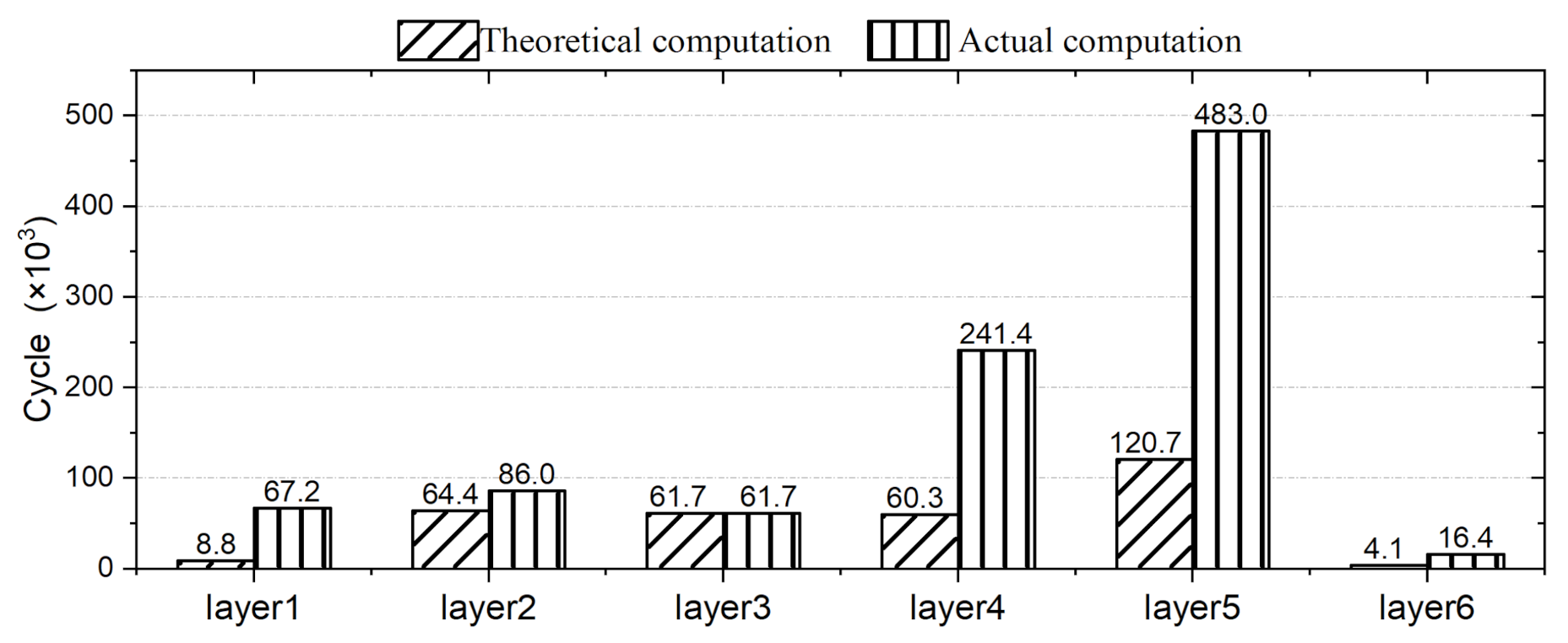
Loop-tiling FPGA-based approaches suffer from a low compute unit (CU) efficiency due to their large number of redundant computations when conducting inference tasks for CNNs. The CUs used in existing approaches are not efficiently utilized and the number of computations that takes place in CUs is redundant. The Design Automation Conference System Design Contest (DAC-SDC) is a UAV application contest. The task of the contest is to train the neural network according to the data set and build a customized accelerator system on the FPGA platform to complete object detection inference. Loop-tiling accelerators are very popular in DAC-SDCs. Skynet is one of the loop-tiling accelerators designed by the DAC-SDC2019 champion team. We compared the actual and theoretical computation results of Skynet layer by layer. As shown in Figure 1, the redundant computation in CNN inference—that is, the calculation of 0 value to complement the computation unit—accounts for about 56% of the total. Such a large quantity of redundant cycles can greatly reduce the overall performance of CNN inference. Therefore, the existing FPGA-based approaches cannot meet the performance requirements of CNN inference at present.
The reasons behind these technical difficulties are as follows. On one hand, all the existing FPGA-based approaches use a single CU across different convolutional layers (CONV-layers), ignoring the fact that no single CU can perform best on all of the different CONV-layers. The use of a fixed CU size can lead to much redundant computation, thus causing overall performance degradation. On the other hand, a CNN model consists of different CONV-layers, and the computation workloads of any two CONV-layers are usually asymmetric. Such workload asymmetry results in large performance fluctuations when using a single CU for CNN inference computing. Once again, this fact is not considered in the design of existing FPGA-based approaches.
Hence, we propose DSCU, an approach that aims to accelerate CNN inference using dual sizes of CUs in FPGAs. The key idea of DSCU is to select the best combination of CUs with dynamic programming scheduling for each CONV-layer of a given CNN. DSCU selects the best combination of CUs via dynamic programming scheduling for each CONV-layer, then assembles a computing solution for the given CNN to deploy on FPGAs. We implement DSCU in the most advanced FPGA-customized networks, and the experimental results show that the DSCU can achieve a performance density of GOPs/slice, which represents a speed increase of 7.47×, 4.13×, and 1.28× compared with the results of M. Peemen [8], C. Zhang [9], and C. Hao [10], respectively.
The technical contributions of this paper are threefold:
- We propose DSCU, which selects the best combination of CUs through dynamic programming to solve a common problem in accelerating CNN inference, redundant computation.
- We introduce a CNN accelerator design of DSCU for the Xilinx Zynq ZU3EG.
- We conduct a comprehensive evaluation of DSCU over multiple CONV-layers and FPGA-customized networks.
The rest of this paper is organized as follows. Section 2 presents a further optimization challenge by reviewing the mainstream accelerators. Section 3 shows the details of the DSCU approach. Section 4 verifies the superiority of the DSCU through various experiments. Finally, we conclude this paper in Section 5. This paper is based on our previous work published in MCSoC 2021 [11], with substantial extensions. In this paper, the design of CU is described, and the CU latency is modeled in more detail. A weighted voting method is proposed to generate CNN solution. More experiments were carried out to verify the effect of DSCU on redundant computations.
2. Background and Motivation
2.1. Convolutional Neural Network
The CNN is composed of a variety of computing layers, including the CONV-layer, the deeply separable convolutional layer [12], the pooling layer, the full connection layer, and the activation layer. Among these, the CONV-layer is computationally intensive and takes up much of the computing resources, as shown in Algorithm 1. The convolution computation configuration includes the features width C, height R, input channel N, output channel M, kernel size , and slide window S. The total number of convolution computations can be calculated using .
| Algorithm 1: Function CONV |
 |
2.2. High-Level Synthesis of FPGAs
In recent years, we have seen promising developments in high-level synthesis (HLS) for FPGAs [13]. Most FPGA vendors’ HLS compilers are designed to describe accelerated computations in C/C++, which are then synthesized into FPGA accelerators directly in bit stream in the form of RTL or by calling downstream CAD tools. This is evidenced by the wide availability of commercial C/OpenCL-based HLS compilers, such as Xilinx Vivado/Vitis HLS [14] and Intel SDK for OpenCL [15]. However, these are quite different from the traditional performance tuning process of CPU software programming. Achieving a high performance with HLS requires extensive hardware knowledge. Programmers need to apply pragmas directives from vendors to guide the HLS tool to generate the desired accelerator architecture. Loop pipelining is a key optimization technique used in HLS to improve system throughput by overlapping the execution of operations from different loop iterations. To further increase the hardware parallelism, HLS designs commonly use loop unrolling in combination with pipelining to increase the number of parallel operations per pipeline.
2.3. Related Work on Loop-Tiling CNN Accelerator
The early research in this area has focused on the acceleration of convolution computation [9]. Fixed sizes of CUs have been deployed for computing. Loop unrolling and loop pipelining have been used for parallel processing. An accelerator of the loop-tiling method is proposed here. During the process of loop tiling, a common problem is that the data are difficult to calculate.
Previous work has often used hardware customization techniques to address the performance challenges of FPGA-based accelerators. A great deal of work has been carried out to optimize RTL from different perspectives, including custom compute engines and custom data representations. FESA is a fusion-enabled systolic architecture for sparse neural networks which can reduce PEs’ no-load rate and improve performance by supporting channel fusion [16]. HLS tools provide programmers with high-level abstractions and derive efficient RTL from them, saving programmers from extensive hand-coding and tuning using low-level HDLs [13]. HLS tools have been increasingly deployed for FPGA-based acceleration. Much of this work is implemented using HLS. This allows a better focus on accelerator scheduling and architecture design, rather than being limited by hardware programming. For massive and different layer sizes, deep neural architecture (DNA) reconfigure data paths to support a hybrid data reuse pattern, which reduces the total energy consumption by 5.9–8.4 times compared to conventional methods [17]. To provide a high utilization of data alignment for accelerator computing, an appropriative scheduling module was designed to order sparsely compressed input data. This way, the processing efficiency can be improved [18]. With the development of a CNN, the network often has the same efficient computing structure. Based on depth-separable convolution repetitive structures, a tile-level pipeline of the loop-tiling approach is proposed to improve the CNN accelerator. The time-division multiplexing structure is used to process the data flow, which further improves the performance. This method was used in the DAC system design contest and won the championship in 2019 [7]. An FPGA-based MobileNetV2 accelerator used stream interfaces and autogenerated control to enable the fast design of flexible architectures [19]. It can achieve a high throughput of 1050 frames per second at a power consumption of 34 watts under full load with the accelerator framework using Quartus Prime.
The optimization of the accelerator configuration is the key challenge when deploying the customized CNN accelerator. There are two main aspects that need to be considered when tuning the CNN: the neural network structure and the hardware resources. The mathematical model was constructed to optimize the accelerator according to the specific application [20]. Tomato was used with a mixture of short powers of 2 which were combined with the templated hardware designs to automatically produce efficient inference circuits in FPGAs [21]. C. Hao optimized the number of channels by top-down heuristic searching on a single CU considering DNN-specific characteristics [10]. A programming flow for CNN on FPGA is proposed to generate high-performance accelerators by assembling CNN preimplemented components as a puzzle based on the graph topology [22]. This method can predict the minimum resources necessary without needing to synthesize any HDL code.
2.4. Motivation
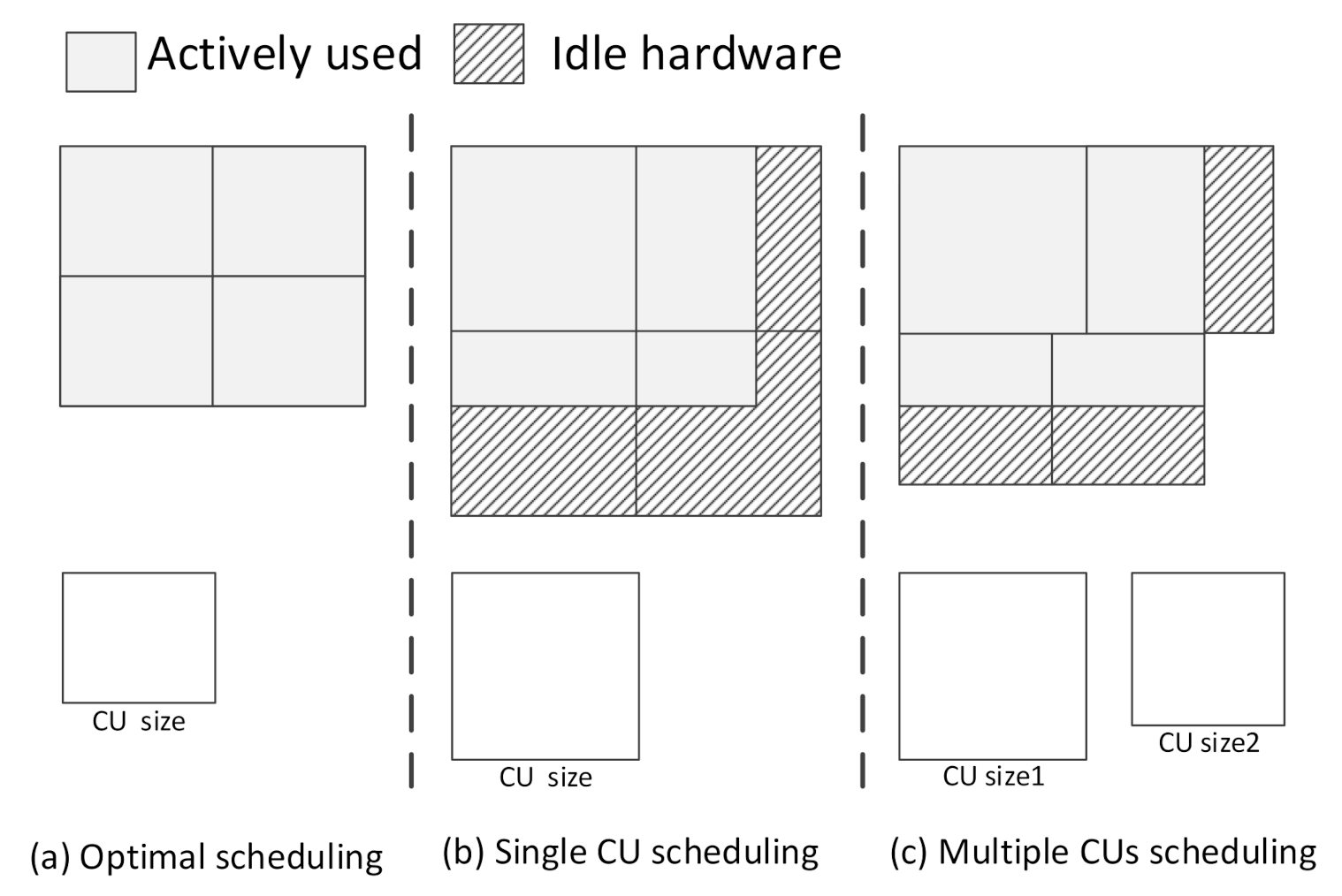
We find that all features can be integrated by CUs without any redundant computation in an ideal loop-tiling CNN accelerator, as shown in Figure 2a. However, the accelerator with a single CU has to deal with different CONV-layers. Additionally, even the neural network designed using a hardware–software codesign cannot avoid redundant computation, as shown in Figure 2b. Essentially, the problem is that the CU is single. The use of different sizes of CUs can ease this problem in principle. Some CUs with efficient sizes can be listed as candidate CUs. However, each CONV-layer of a given CNN will need different combinations of CUs. Therefore, choosing the best combination of CUs to avoid redundant computations with limited resources is a challenge. The principle of choice needs to be considered, including the resource usage and transmission latency of a CU. We consider that the redundant computation can be eliminated by choosing dual sizes of CUs from candidate CUs for each layer, as shown in Figure 2c. By reviewing the past studies on FPGA-based accelerators, we find that redundant computation is closely related to the four dimensions of CU size: height, width, number of input channels, and number of output channels. Since height and width are closely related to practical applications, which are often ignored, it is not effective to optimize height and width using existing optimization methods.
In this case, we propose the use of a scheduling unit to choose a combination of CUs by dynamic programming and assemble the whole combinations for computing. In this way, dual sizes of CUs with efficient scheduling can deal with redundant computation challenges from height–width channel optimization.
3. The DSCU Approach
3.1. Workflow of DSCU
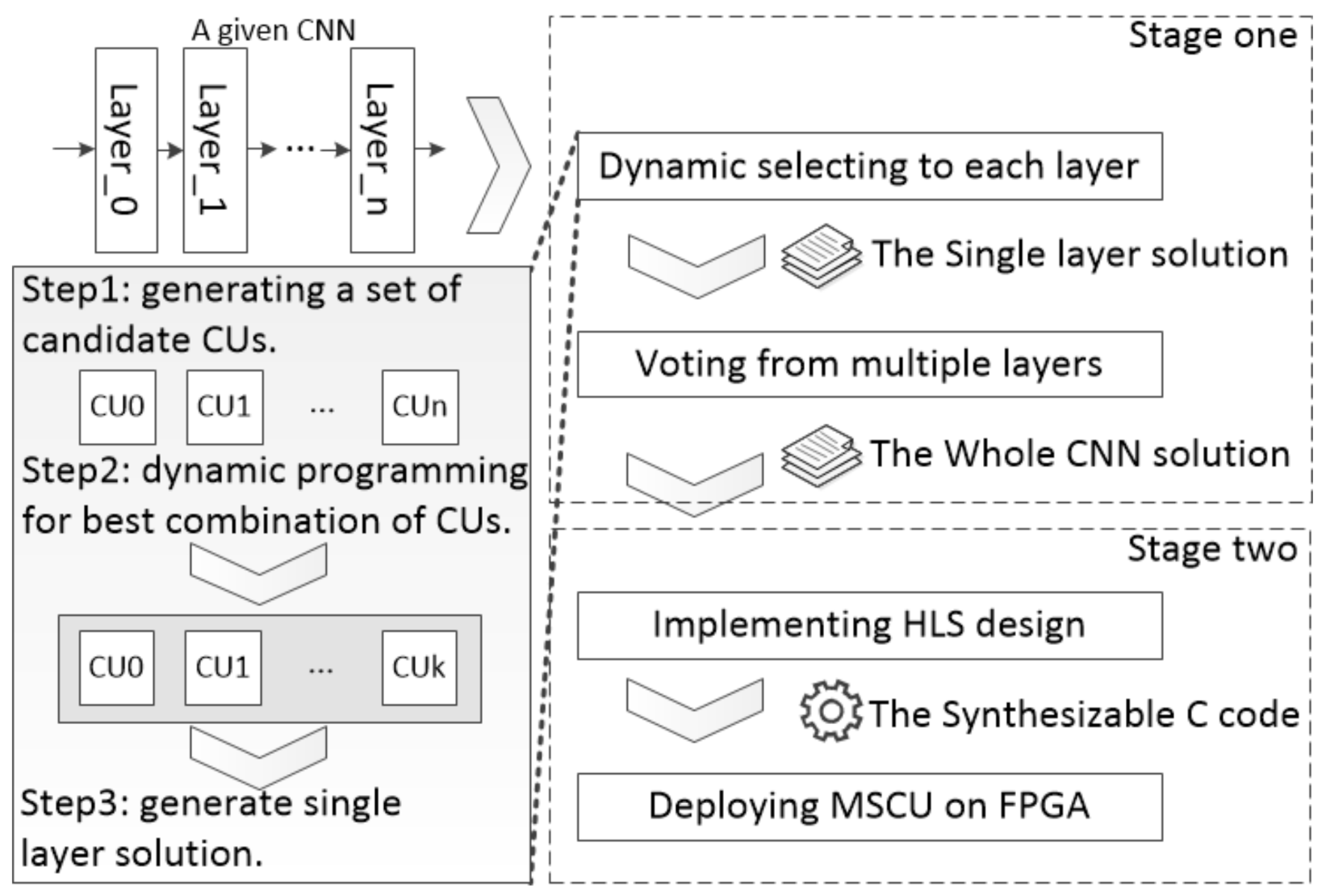
DSCU mainly includes two computing stages: selection and execution (Figure 3). (1) Selection. Firstly, DSCU generates a set of candidate CUs according to the computing workloads of each CONV-layer. Based on the candidate CUs, DSCU selects the best combination of CUs with dynamic programming scheduling for each CONV-layer. Then, DSCU assembles the best combinations into a whole CNN as the computing solution. (2) Execution. Finally, DSCU performs CNN inference on FPGAs with the produced solution.
3.2. Architecture of DSCU
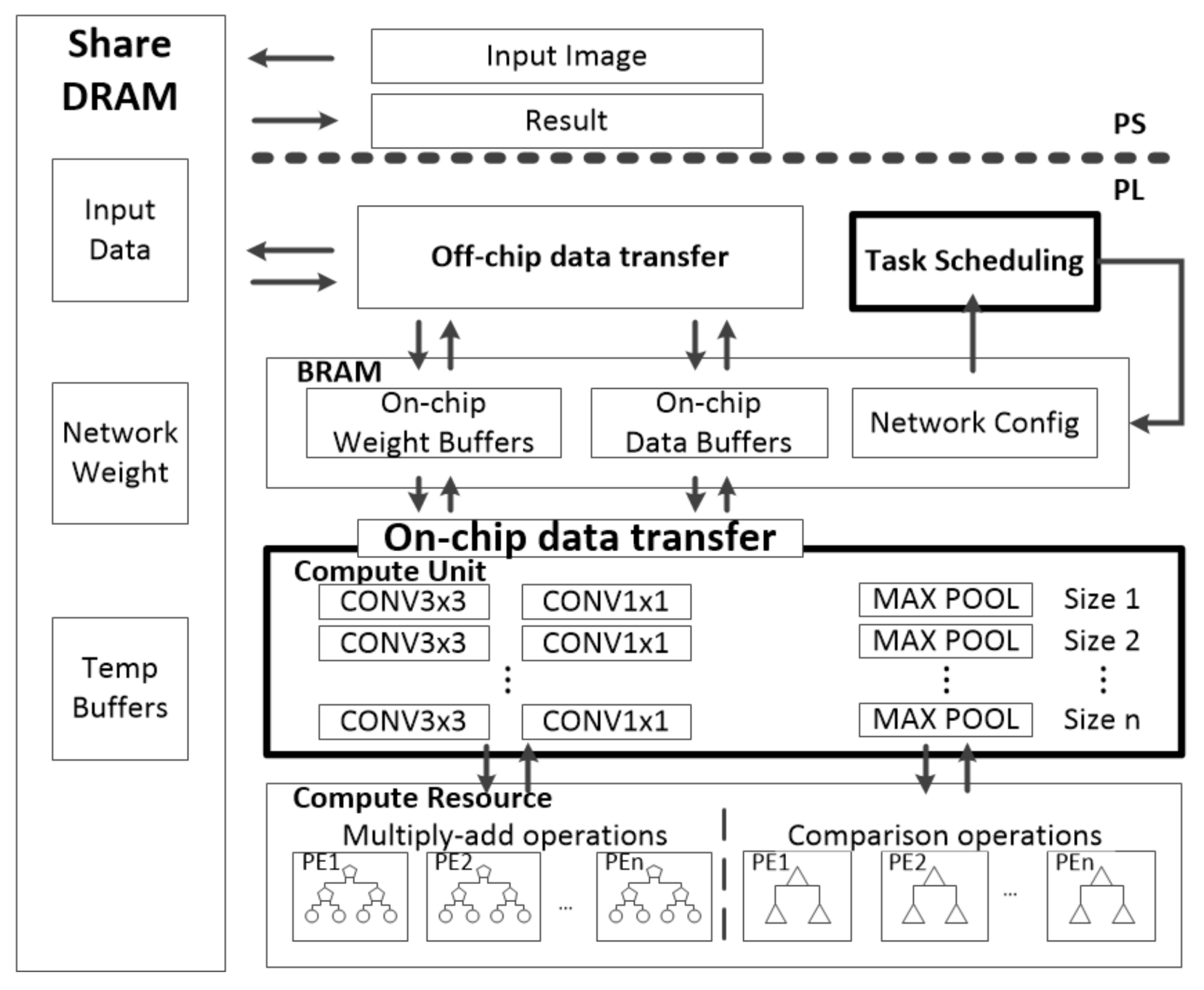
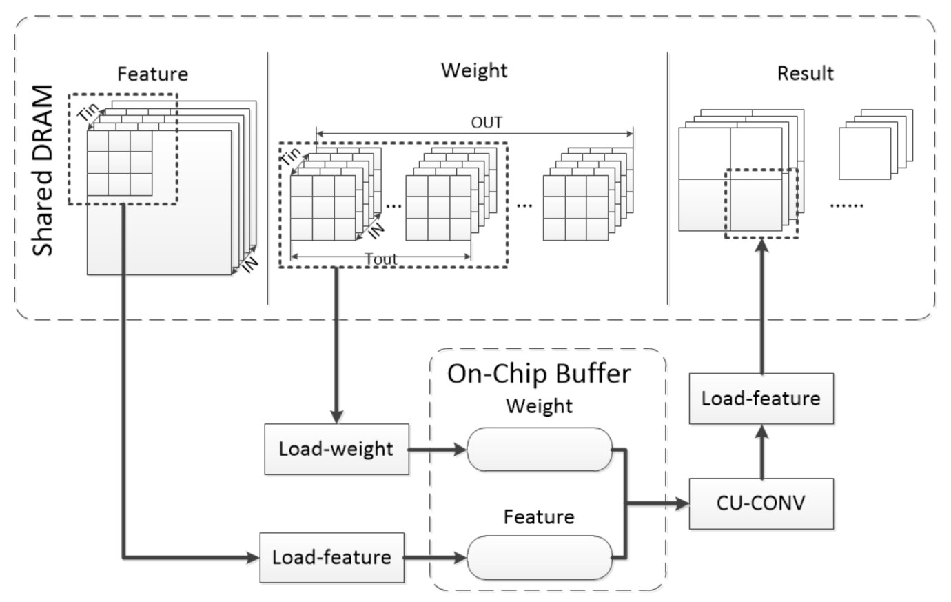
Common FPGA acceleration structures include five parts, which are processing elements (PEs), on-chip buffer, shared dynamic random-access memory (shared DRAM), on-/off-chip interconnect and CUs. A CU is the minimum scheduling unit for computation layers such as convolution and pooling. On this basis, DSCU adds the task scheduling unit and modifies single CU to candidate CUs, as shown in Figure 4. All data for processing are stored in the shared DRAM. The CNN configuration data are stored in the on-chip task-scheduling unit in advance. The task-scheduling unit chooses the best combination of CUs from candidate CUs for each CONV-layer of a given CNN as the whole computing solution.
With the produced solution, on-/off-chip interconnects move the data from the shared DRAM to the on-chip buffer. Furthermore, the data are delivered to the CUs to complete a given CNN inference iteratively. The CU is one of the computation units with a fixed size, such as CONV3×3, CONV1×1, MAXPOOL in Figure 4. The CU performs computations by calling PE. The PE was designed as a tree-structured computing unit, which is the lowest level unit in Figure 4.
We optimized for the redundant computation problem of the accelerator. Through the coordination of the task-scheduling unit with dynamic programming and dual sizes of CUs, DSCU can alleviate redundant computation to the greatest extent.
3.3. Design Details of Accelerated CNN Inference
DSCU was designed for CNN inference. DSCU can complete CNN layer computations such as convolution, pooling, and activation. Algorithm 2 is an example of DSCU computing a single CONV3×3. Computing a layer can be divided into four basic units: Load-weight, Load-feature, CU-CONV3×3, Save-result. The computation layer has been divided by the task-scheduling unit into smaller-size layers that fit the CU to complete. The Load-weight and Load-feature units carry the weight and feature map from the shared DRAM to the on-chip buffer, respectively, according to the task-scheduling unit. The CU-CONV3×3 unit obtains data from the on-chip buffer to compute. The Save-result unit restores the result to the original format according to the task-scheduling unit and moves it to the shared DRAM. This process is repeated until all computations are complete. This process is shown in Figure 5.
| Algorithm 2: Computing a single CONV3×3 layer |
 |
A CU requires two aspects of data from the on-chip buffer by Load-weight and Load-feature. These two parts of the data transfer do not interfere with each other, so they can be carried out synchronously. To sum up, the execution sequence of a single CONV3×3 is shown in Figure 6. This indicates that n executions are required to complete the computation.
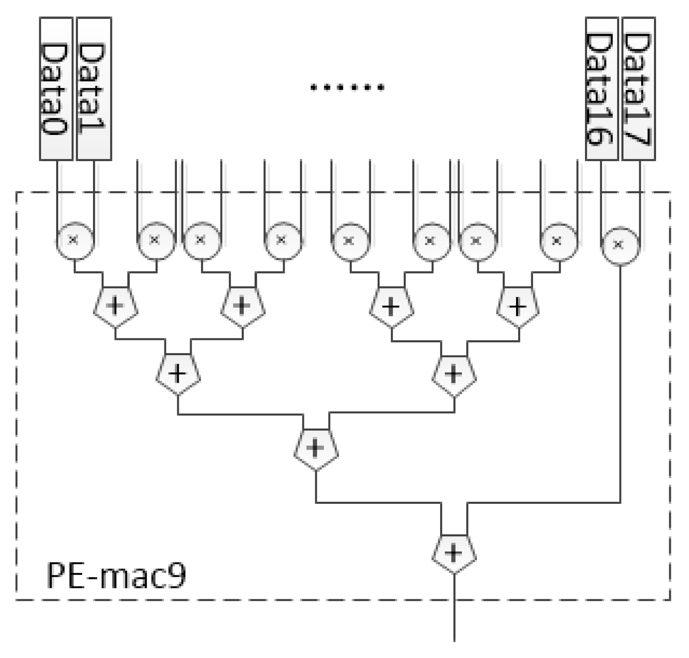
CU-CONV3×3 is one of the convolution computation units with a fixed size. The essence of CONV-layer is a multiplication and addition (MAC) operation. For the CONV3×3, the PE in DSCU was designed as an 18 fixed-point number arithmetic unit based on a MAC tree, as shown in Figure 7. In CU-CONV3×3, the last layer of the loop body is completely unrolled, so CU-CONV3×3 will call the PEs to participate in the computation, as shown in Algorithm 3. “#pragma HLS PIPELINE” and “#pragma HLS UNROLL” are defined by Xilinx HLS to generate the desired architecture.
| Algorithm 3: Function CU-CONV3×3 |
 |
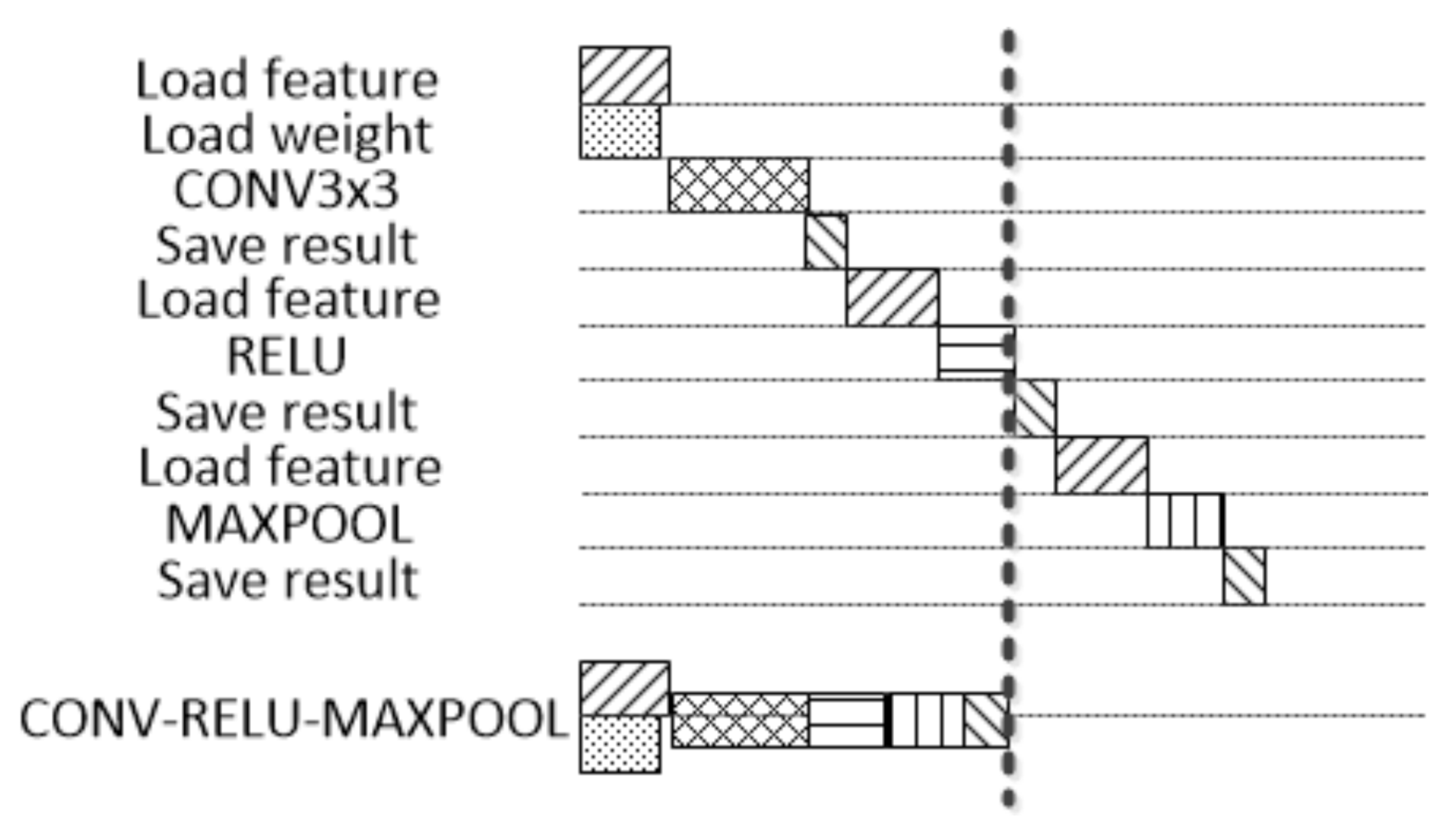
Other computation layers are designed similarly. In actual CNN, the convolution, pooling, and activation layers are usually executed consecutively. DSCU adopts the method of a CONV-RELU-MAXPOOL fusion layer. The CU for these layers can be performed in series, and the results can be transferred out of the chip at the end. This method can save the latency of Save-result and Load-feature in Figure 8.
3.4. The Latency Model of Basic Unit in DSCU
In order to better coordinate with the scheduling module, according to the above design, the latency of Load-weight, Load-feature, CU and Save-result can be summarized for evaluation. The symbols used in this section are listed in Table 1.
The functions of Load-feature and Save-result are to transport the feature map to on-chip and to transport the feature map to off-chip, respectively. The latency required is the time of the feature map transportation, and one datum can be transported each time, as shown in Equations (1) and (2). The function of Load-weight is to transport the weights required by the convolution layer to the on-chip. The required latency is the time of the weights, such as CONV3×3 weights, CONV1×1 weights, which can carry one datum at a time, as shown in Equation (3).
According to the corresponding algorithm, the latency of a CU can be obtained. A CU was designed as a unit with parallel computing capability. Parallelism can be divided into two types, the parallelism of channel dimension and the special parallelism brought by a PE. For instance, is the parallelism in CONV-layer and is the parallelism in Pool-layer, as shown in Equations (4)–(6).
In addition, a CU for the depth separable convolution was designed. The depth separable convolution consists of CONV-depthwise and CONV-pointwise. For CONV-depthwise, a dedicated CU was designed, and the latency of the CU is shown in Equation (7). CONV-pointwise can be complete with CU-CONV with , as shown in Equation (8).
3.5. Task Scheduling with Dynamic Programming for a Single Layer
The dynamic programming method is an effective method to solve optimization problems. The three elements of the programming problem include the objective function, decision variable and constraint condition. For the above design, the core of the single layer solution was to determine the size and quantity of CUs. So the application can be modeled as Equations (9)–(11).
There are n CUs with different sizes. represents the latency required for the xth CU to complete computation. represents the number of DSP computing resources required to be consumed by the xth CU. represents the number of BRAM storage resources that need to be consumed by the xth CU. Generally, the design will not be limited to other resources for FPGA. So we just discuss DSP and BRAM’s limitations in this model. Based on the analysis from the previous section, it is proved that can be approximately proportional to and in this model the latency can be estimated by . The Latency size of CUs was arranged in descending order artificially.
Equation (10) represents the objective function and is the total latency used in computing. As designed in the previous part, the CUs are independent of each other, so they can be executed in parallel. Parallel tasks are uniformly assigned each time. When a task contains , the latency of tasks in parallel should be . Now, the task executes times (without ) instead. If are greater than 0, the latency of the next tasks is . Otherwise, the latency is ignored, and so on in Equation (9). The reason for this calculation is that the task-scheduling unit of the DSCU is designed to synchronize instructions. That is, the next instruction will be issued only after all CUs instructions are completed. Equation (11) is a constraint, where and , respectively, represent the number of DSP and BRAM resources of the target board. This model is not only limited to dual sizes of CUs and can handle the scheduling of multiple sizes of CUs. For DSCU, n is 2.
We used a dynamic programming method to solve the mathematical model. First, to facilitate the elaboration, some definitions are proposed:
Definition 1.
represents the numbering set of the CUs.
Definition 2.
is a triple, i.e., . describes a CU ’s attributes: is the width of the unit of data to be processed, is the height of the unit of data to be processed, and is the latency of CU.
Definition 3.
is a -tuple, i.e., , n is the number of units’ sizes. is used to record the intermediate amount of problem solving for optimization problems. represents the number of CUs in the current space of x. represents the heuristic function for optimization, which means the latency cost required by calculating CUs in the current space. The latency cost is defined in Equation (9).
Definition 4.
A two-dimensional array , where i is the width and j is the height. describes how to save the maximum latency and the information record of full load computation for each CU under the conditions that the width of the data unit is i and the height is j. The latency cost is stored in , and the corresponding number of CUs is stored in .
Definition 5.
An array is used to record a CU ’s attributes, where x is the number of CU.
According to the problem, we give the recursion Equations (12)–(14) of and , where k is used to traverse , and the triadic operation means that if equation C is true, it is A; otherwise, it is B. According to the recursive equation, this updates the solution in the current case of i and j in .
In the actual solution, i and j, respectively, represent the width and height of the feature data, and the optimal solution is recorded in . The task-scheduling unit selects the best combination of CUs with dynamic programming scheduling and the single layer optimal solution can be generated for the complete inference. Such task scheduling chooses the best combination of CUs that make full use of the resources of the target board and avoid the problem of redundant computation as much as possible. In this way, the feature map can be efficiently allocated to each CU for parallel processing.
3.6. Generation of a CNN Solution by Voting
A complete CNN consists of multiple layers. Through the single-layer scheduling the solution for each layer can be obtained. A CNN can only be implemented with one solution. In this section, a voting method is presented to determine the CNN’s final solution.
It was assumed that a CNN was constituted of n layers, and the voting method was divided into three steps:
- Firstly, all optimal single layer solutions were obtained by the single-layer scheduling. It was assumed that there are k different solutions.
- Secondly, k types of solutions were voted on. One vote was counted for each layer that used the ith solution, .
- Finally, the solution with the highest number of votes was selected as the CNN’s final solution.
The weights of all layers voting were exactly the same, that is, the number of votes for each layer was 1. Furthermore, the combination with the highest number of votes was finally counted as the final plan, which achieved a good result. However, the different computation amount of each layer cannot be fully considered this way. We believe that each layer has a different contribution to the final global latency. The layer with a smaller contribution to the global latency can be set with a small weight. The layer with a larger contribution to the global latency can be set with a large weight.
To this end, we adopted a different weight method to take advantage of this feature. Specifically, the latency of each layer and the computation amount are positively correlated from the analysis in the previous section. Therefore, it is more appropriate to correlate the weight of voting with the computation amount. The voting weight of each layer can be obtained by normalizing the computation amount of each layer as shown in Equation (15). is the weight of the ith layer. is the computation amount of the ith layer. , are the maximum and minimum computation amount in all layers.
When the votes were finally counted, the result was accumulated according to the weights, as shown in Algorithm 4.
| Algorithm 4: Voting from multipe layers |
 |
Our method has more advantages in running time. C. Zhang [9] adopted the method of enumeration to select the final solution, and AlexNet was used for testing, requiring approximately 1,000,000 execution cycles. With 10 candidate CUs selected, the theoretical running period of our method is about 600,000 cycles. The specific DSCU acceleration performance is discussed in the next section.
4. Results
Various indicators of comparison between DSCU and some previous typical loop-tiling accelerators [8,9,10] were derived. Our evaluation showed that DSCU can perform CNN inference efficiently and make better use of resources on an FPGA. In order to verify the effect of DSCU on redundant computing problems, we carried out a comparison between a single CU accelerator and DSCU including complete CNN and computational layer experiments.
4.1. Experimental Setup
Software and hardware setup: We implemented DSCU on Xilinx Vivado + HLS 2018.3 software. We used Xilinx ultra96 V2 as the target platform. Ultra96 V2 consisted of a XCZU3EG FPGA chip, ARM Cortex-A53 and 2 G DDR3 memory. There were 216 Block RAMs(BRAMs), 70,560 LUT elements (LUTs), 141,120 flip-flops (FFs), and 360 DSPs on Xilinx Zynq ZU3EG.
DSCU setting: After preliminary evaluation and certification, the Ultra96 v2 DSCU can work at 100 MHz on average. DSCU can run up to 300 MHz after fine tuning of the Load-wegiht, Load-feature and Save-result units.
Evaluation methodology: DSCU was deployed on the FPGA of Ultra96 V2. A test program based on Xilinx PYNQ framework was built on the ARM of Ultra96 V2. This program had these functions: The data were loaded into DDR3 memory. The PYNQ interface of the FPGA was invoked to map the DSCU hardware physical address to the memory. DSCU was enabled and the timer was started at the same time. The timer was stopped when DSCU hardware execution ended. The execution time was the latency for DSCU. We evaluated DSCU from two aspects, namely, inference latency and redundant computation rate, and we conducted a set of experiments as follows:
- On one hand, we used DSCU to run CNNs comparing with other accelerators for an overall evaluation, in order to verify that DSCU can complete CNN inferences faster.
- On the other hand, we forced the effect of DSCU on redundant computing problems. We chose some customized CNNs and customized layers with different input feature maps for testing.
4.2. Overall Performance
In the software part, the neural network firstly pretrained with low bit quantization on the GPU. Then, in the hardware part, DSCU was implemented based on the HLS tool. The placement and routing was completed with the Vivado tool set. All of the following experiments were carried out in this way. This mainly discusses inference latency and redundant computation rate, not the accuracy of the neural network. The reason is that the accelerated design of DSCU in this paper does not affect the accuracy of the neural network. The quantization algorithm is the key to affect the accuracy of the neural network, and the LSFQ [23] method was used in this paper. This is described in our previous work, where the influence of the hardware-awareness quantization on the accuracy of neural network was discussed in detail. The resource utilization of our implementation is reported in Table 2. DSCU has almost fully utilized the FPGA’s hardware resource.
In Table 3, various existing FPGA-based CNN accelerators are listed and compared to our implementation in this work. Skynet was the champion CNN for DAC-SDC2019. The team presented a design of an accelerator for Skynet and analyzed its performance [10]. Ultranet was the champion CNN for DAC-SDC2020 [23]. As shown in the eighth row of Table 3, our accelerator has a throughput of 29.59 GOPS. Compared with C.Hao [10], DSCU increases the throughput by 1.27× on average.
Since different work exploits different parallelism opportunities and use different FPGA platforms, it is hard to have a straightforward comparison between them. In order to provide a fair comparison, the performance density [9] is used in Table 3. As shown in the last row of Table 3, our implementation achieves GOPs/slice, which is the highest performance density in Table 3. DSCU achieves a speedup of up to 7.47×, 4.13×, and 1.28× compared with M.Peemen [8], C.Zhang [9], and C.Hao [10], respectively.
4.3. Observed Experiments with Redundant Computation
Experiments were conducted from the perspective of the entire network and a single computation layer. The performance of the DSCU was tested and compared with that of a single CU accelerator. According to the results, we observed the solution of DSCU to the redundant computing problem.
DSCU was tested on Mnist-Lenet [24], DJI-UAV-Skynet [7], and DJI-UAV-Ultranet [23]. DJI-UAV [25] is the dataset of DAC-SDC. Based on the network characteristics, the CU configuration for a single CU accelerator and DSCU is shown in Table 4. To optimize scheduling under Ultra96 V2 resource constraints, the final configuration of DSCU was two identical CUs.
DSCU can effectively reduce the computation latency. At the same time, due to the design of dual CUs, the resources of board can be more fully utilized, as shown in Table 5. Similarly, these experiments were also carried out on Ultra96 V2 at a frequency of 100 MHz The customized CNNs usually consider hardware computing. On the basis of these networks, DSCU can be further optimized from a single CU accelerator, the average latency can be sped up by about , and the redundant computation rate decreased by an average of 30%. Lenet is a classical simple classification network. The inference latency of the actual network can still be reduced by about 20.9%. For Ultranet and Skynet, DSCU boosts computing efficiently with the combination of CUs. Another advantage of DSCU is reflected in Lenet’s evaluation. Because the Lenet has only a two-layer convolution, the ideal accelerator can be achieved in the dimension of width and height. The existing redundant computation lies in the channel dimension. However, DSCU can also make full use of the platform resources for parallel computing.
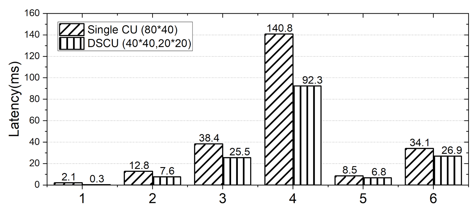
Next, we tested DSCU for customized layers. We deployed DSCU on the hardware platform according to the configuration in Table 6. The accelerator with a single CU was 32 × 32 × 80 × 40. There were two kinds of candidate CUs, 32 × 32 × 40 × 20 and 32 × 32 × 20 × 20, according to the platform resource limitation. All experiments were carried out at the frequency of 300 MHZ.
The experimental results are shown in Figure 9. The vertical axis is the number of cycles computing the convolution. It can be seen that compared with the single CU accelerator, DSCU has obvious savings in latency, which can be proved to avoid some redundant computation. The tested samples covered most of the feature maps situations, as a result, efficiency was improved by 39.2% on average. Among them, the test samples 1–4 had a large redundant computation under the current hardware accelerator setting, so the computation efficiency was significantly improved. In the test samples 5–6, neither of the two accelerators had redundant computation theoretically, and the optimization of scheduling increased parallelism, thus improving the computational efficiency.
5. Conclusions
In this paper, the common problem of redundant computation of FPGA-based CNN accelerators was discussed. To solve this problem, DSCU was proposed. We implemented a CNN accelerator DSCU on FPGA. Firstly, DSCU selects the best combination of CUs via dynamic programming scheduling for each CONV-layer. Then, DSCU assembles the best combination into a given CNN as the computing solution. Finally, DSCU performs CNN inference on FPGAs with the produced solution. The experiment showed that DSCU was more effective than the existing methods in accelerating CNN inference. DSCU was tested on customized CNNs and customized layers. The results showed that the average redundant computation rate can be alleviated by 30%.
Author Contributions
Conceptualization, Z.B. and W.Z.; methodology, J.G. and W.Z.; software, J.G. and H.D.; validation, J.G. and H.D.; formal analysis, J.G.; investigation, J.G.; data curation, J.G.; writing—original draft preparation, J.G.; writing—review and editing, J.G. and H.D.; visualization, J.G. and H.D.; supervision, Z.B. and W.Z.; project administration, W.Z.; funding acquisition, Z.B. and W.Z. All authors have read and agreed to the published version of the manuscript.
Funding
The work was partially supported by National Key R&D Program of China under grant number 2017yfc0803300, and National Natural Science Foundation of China under grant number 41776186.
Institutional Review Board Statement
Not applicable.
Informed Consent Statement
Informed consent was obtained from all subjects involved in the study.
Data Availability Statement
Data is contained within the article.
Conflicts of Interest
The authors declare no conflict of interest.
References
- Qiu, H.; Ma, Y.; Li, Z.; Liu, S.; Sun, J. BorderDet: Border Feature for Dense Object Detection. In Proceedings of the Computer Vision—ECCV 2020, Glasgow, UK, 23–28 August 2020; pp. 549–564. [Google Scholar]
- Xu, B.; Lu, C.; Guo, Y.; Wang, J. Discriminative Multi-Modality Speech Recognition. In Proceedings of the 2020 IEEE/CVF Conference on Computer Vision and Pattern Recognition, CVPR 2020, Seattle, WA, USA, 13–19 June 2020; pp. 14421–14430. [Google Scholar]
- Peng, H.; Li, J.; Wang, S.; Wang, L.; Gong, Q.; Yang, R.; Li, B.; Yu, P.S.; He, L. Hierarchical Taxonomy-Aware and Attentional Graph Capsule RCNNs for Large-Scale Multi-Label Text Classification. IEEE Trans. Knowl. Data Eng. 2021, 33, 2505–2519. [Google Scholar] [CrossRef] [Green Version]
- Jia, Y.; Shelhamer, E.; Donahue, J.; Karayev, S.; Long, J.; Girshick, R.B.; Guadarrama, S.; Darrell, T. Caffe: Convolutional Architecture for Fast Feature Embedding. In Proceedings of the ACM International Conference on Multimedia, Orlando, FL, USA, 3–7 November 2014; pp. 675–678. [Google Scholar]
- Chen, T.; Du, Z.; Sun, N.; Wang, J.; Wu, C.; Chen, Y.; Temam, O. DianNao: A small-footprint high-throughput accelerator for ubiquitous machine-learning. In Proceedings of the Architectural Support for Programming Languages and Operating Systems, ASPLOS’14, Salt Lake City, UT, USA, 1–5 March 2014; pp. 269–284. [Google Scholar]
- Xu, P.; Zhang, X.; Hao, C.; Zhao, Y.; Zhang, Y.; Wang, Y.; Li, C.; Guan, Z.; Chen, D.; Lin, Y. AutoDNNchip: An Automated DNN Chip Predictor and Builder for Both FPGAs and ASICs. In Proceedings of the FPGA’20: The 2020 ACM/SIGDA International Symposium on Field-Programmable Gate Arrays, Seaside, CA, USA, 23–25 February 2020; pp. 40–50. [Google Scholar]
- Zhang, X.; Lu, H.; Hao, C.; Li, J.; Cheng, B.; Li, Y.; Rupnow, K.; Xiong, J.; Huang, T.; Shi, H.; et al. SkyNet: A hardware-efficient method for object detection and tracking on embedded systems. In Proceedings of the Conference on Machine Learning and Systems (MLSys), Austin, TX, USA, 2–4 March 2020. [Google Scholar]
- Peemen, M.; Setio, A.A.A.; Mesman, B.; Corporaal, H. Memory-centric accelerator design for Convolutional Neural Networks. In Proceedings of the 2013 IEEE 31st International Conference on Computer Design (ICCD), Asheville, NC, USA, 6–9 October 2013; pp. 13–19. [Google Scholar]
- Zhang, C.; Li, P.; Sun, G.; Guan, Y.; Xiao, B.; Cong, J. Optimizing FPGA-Based Accelerator Design for Deep Convolutional Neural Networks. In Proceedings of the 2015 ACM/SIGDA International Symposium on Field-Programmable Gate Arrays, FPGA’15, Monterey, CA, USA, 22–24 February 2015; pp. 161–170. [Google Scholar]
- Hao, C.; Zhang, X.; Li, Y.; Huang, S.; Xiong, J.; Rupnow, K.; Hwu, W.; Chen, D. FPGA/DNN Co-Design: An Efficient Design Methodology for 1oT Intelligence on the Edge. In Proceedings of the 2019 56th ACM/IEEE Design Automation Conference (DAC), Las Vegas, NV, USA, 2–6 June 2019; pp. 1–6. [Google Scholar]
- Bao, Z.; Guo, J.; Li, X.; Zhang, W. MSCU: Accelerating CNN Inference with Multiple Sizes of Compute Unit on FPGAs. In Proceedings of the 2021 IEEE 14th International Symposium on Embedded Multicore/Many-Core Systems-on-Chip (MCSoC), Singapore, 20–23 December 2021; pp. 106–113. [Google Scholar]
- Howard, A.G.; Zhu, M.; Chen, B.; Kalenichenko, D.; Wang, W.; Weyand, T.; Andreetto, M.; Adam, H. MobileNets: Efficient Convolutional Neural Networks for Mobile Vision Applications. arXiv 2017, arXiv:1704.04861. [Google Scholar]
- Cong, J.; Liu, B.; Neuendorffer, S.; Noguera, J.; Vissers, K.; Zhang, Z. High-Level Synthesis for FPGAs: From Prototyping to Deployment. IEEE Trans. Comput.-Aided Des. Integr. Circuits Syst. 2011, 30, 473–491. [Google Scholar] [CrossRef] [Green Version]
- Xilinx. Vitis High-Level Synthesis User Guide; Xilinx: San Jose, CA, USA, 2020. [Google Scholar]
- Intel. Intel SoC FPGAs; Intel: Santa Clara, CA, USA, 2020. [Google Scholar]
- Wang, J.; Yu, S.; Yue, J.; Yuan, Z.; Yuan, Z.; Yang, H.; Li, X.; Liu, Y. High PE Utilization CNN Accelerator with Channel Fusion Supporting Pattern-Compressed Sparse Neural Networks. In Proceedings of the 2020 57th ACM/IEEE Design Automation Conference (DAC), San Francisco, CA, USA, 20–24 July 2020; pp. 1–6. [Google Scholar]
- Tu, F.; Yin, S.; Ouyang, P.; Tang, S.; Liu, L.; Wei, S. Deep Convolutional Neural Network Architecture With Reconfigurable Computation Patterns. IEEE Trans. Very Large Scale Integr. (VLSI) Syst. 2017, 25, 2220–2233. [Google Scholar] [CrossRef]
- Wang, D.; Xu, K.; Jia, Q.; Ghiasi, S. ABM-SpConv: A Novel Approach to FPGA-Based Acceleration of ConvolutionaI NeuraI Network Inference. In Proceedings of the 2019 56th ACM/IEEE Design Automation Conference (DAC), Las Vegas, NV, USA, 2–6 June 2019; pp. 1–6. [Google Scholar]
- Knapheide, J.; Stabernack, B.; Kuhnke, M. A High Throughput MobileNetV2 FPGA Implementation Based on a Flexible Architecture for Depthwise Separable Convolution. In Proceedings of the 2020 30th International Conference on Field-Programmable Logic and Applications (FPL), Gothenburg, Sweden, 31 August–4 September 2020; pp. 277–283. [Google Scholar]
- Shen, Y.; Ferdman, M.; Milder, P. Maximizing CNN Accelerator Efficiency Through Resource Partitioning. SIGARCH Comput. Archit. News 2017, 45, 535–547. [Google Scholar] [CrossRef] [Green Version]
- Zhao, Y.; Gao, X.; Guo, X.; Liu, J.; Wang, E.; Mullins, R.; Cheung, P.Y.K.; Constantinides, G.; Xu, C.Z. Automatic Generation of Multi-Precision Multi-Arithmetic CNN Accelerators for FPGAs. In Proceedings of the 2019 International Conference on Field-Programmable Technology (ICFPT), Tianjin, China, 9–13 December 2019; pp. 45–53. [Google Scholar]
- Kwadjo, D.T.; Mbongue, J.M.; Bobda, C. Exploring a Layer-based Pre-implemented Flow for Mapping CNN on FPGA. In Proceedings of the 2021 IEEE International Parallel and Distributed Processing Symposium Workshops (IPDPSW), Portland, OR, USA, 17–21 June 2021; pp. 116–123. [Google Scholar]
- Bao, Z.; Zhan, K.; Zhang, W.; Guo, J. LSFQ: A Low Precision Full Integer Quantization for High-Performance FPGA-Based CNN Acceleration. In Proceedings of the 2021 IEEE Symposium in Low-Power and High-Speed Chips (COOL CHIPS), Tokyo, Japan, 14–16 April 2021; pp. 1–6. [Google Scholar]
- Lecun, Y.; Bottou, L.; Bengio, Y.; Haffner, P. Gradient-based learning applied to document recognition. Proc. IEEE 1998, 86, 2278–2324. [Google Scholar] [CrossRef] [Green Version]
- Xu, X.; Zhang, X.; Yu, B.; Hu, X.S.; Rowen, C.; Hu, J.; Shi, Y. Dac-sdc low power object detection challenge for uav applications. IEEE Trans. Pattern Anal. Mach. Intell. 2019, 43, 392–403. [Google Scholar] [CrossRef] [PubMed] [Green Version]
Figure 1.
Comparison of actual computation and theoretical computation on Skynet [7].
Figure 1.
Comparison of actual computation and theoretical computation on Skynet [7].

Figure 2.
Three common situations in CNN accelerator [11].
Figure 2.
Three common situations in CNN accelerator [11].

Figure 3.
Workflow of DSCU [11].
Figure 3.
Workflow of DSCU [11].

Figure 4.
Architecture of DSCU [11].
Figure 4.
Architecture of DSCU [11].

Figure 5.
The process of CONV-layer computing in DSCU [11].
Figure 5.
The process of CONV-layer computing in DSCU [11].

Figure 6.
The execution sequence of a CONV3×3 [11].
Figure 6.
The execution sequence of a CONV3×3 [11].

Figure 7.
The structure of PE-CONV3×3.

Figure 8.
The comparison between CONV-RELU-MAXPOOL fusion layer and normal layer.

Figure 9.
Comparison of the latency cycles of customized layers.


Table 1.
List of symbols.
| Symbol | Description |
|---|---|
| The width of the feature map for a CU | |
| The height of the feature map for a CU | |
| The input channel of a CU (it is also the channel of the feature map) | |
| The output channel of a CU | |
| K | The kernel of the computation layer |
| The degree of parallelism for channel dimension | |
| Computations that can be performed synchronously in CONV-layer | |
| Computations that can be performed synchronously in MAXPOOL-layer |
Table 2.
FPGA resource utilization.
| Resource Utilization | DSP | BRAM | LUT | FF |
|---|---|---|---|---|
| DSCU | 88% (317/360) | 49% (106/216) | 66% (46,675/70,560) | 36% (50,154/141,120) |
Table 3.
Performance of comparsion between DSCU and existing accelerators [11].
Table 3.
Performance of comparsion between DSCU and existing accelerators [11].
| ICCD2013 [8] | FPGA2015 [9] | DAC2019 [10] | DSCU | |
|---|---|---|---|---|
| Precision | fixed point | 32 bit float | weight: 11 bits activation: 9 bits | weight: 8 bits activation: 8 bits |
| Frequency | 150 MHz | 100 MHz | 215 MHz | 300 MHz |
| Platform | Virtex6 VLX240T | Virtex7 VX485T | Zynq ZU3EG | Zynq ZU3EG |
| FPGA capacity | 37680 slices, 768 DSP | 75900 slices, 2800 DSP | 8800 slices, 360 DSP | 8800 slices, 360 DSP |
| CNN | – | Alexnet | Skynet | Ultranet [23] |
| Model size | 2.74 GMAC | 1.33 GLOP | 0.46 GMAC | 0.20 GMAC |
| Performance | 17.0 GOPs | 61.62 GOPs | 23.15 GOPs | 29.59 GOPs |
| Performance Density | GOPs/slice | GOPs/slice | GOPs/slice | GOPs/slice |
Table 4.
The CU configuration for a single CU accelerator and DSCU [11].
Table 4.
The CU configuration for a single CU accelerator and DSCU [11].
| Accelerator Configuration (Tin, Tout, Tw, Th) | Single CU | DSCU | |
|---|---|---|---|
| CU | CU1 | CU2 | |
| MNIST-Lenet | 16 × 16 × 16 × 16 | 16 × 16 × 8 × 8 | 16 × 16 × 8 × 8 |
| DJI-UAV-Skynet | 16 × 16 × 40 × 40 | 16 × 16 × 20 × 20 | 16 × 16 × 20 × 20 |
| DJI-UAV-Ultranet | 16 × 16 × 40 × 40 | 16 × 16 × 20 × 20 | 16 × 16 × 20 × 20 |
Table 5.
Comparison of performance by DSCU and existing accelerators on customized CNNs.
| Accelerator | Ultranet | Skynet | Lenet | |||
|---|---|---|---|---|---|---|
| Single CU | DSCU | Single CU | DSCU | Single CU | DSCU | |
| Latency (ms) | 456 | 291 | 972 | 664 | 3.54 | 2.8 |
| Speedup | ||||||
| Redundant computation rate | 70.5% | 40.5% | 45.3% | 20.0% | 8.3% | 8.3% |
| Resource usage | ||||||
| FFs | 38,891 | 50,154 | 41,560 | 53,321 | 23,387 | 29,873 |
| LUTs | 35,296 | 46,675 | 36,102 | 49,821 | 19,782 | 28,165 |
| DSPs | 231 | 317 | 261 | 359 | 99 | 201 |
| BRAMs | 92 | 106 | 85 | 127 | 35 | 52 |
Table 6.
The configuration of customized layers.
| No. | Configuration | ||
|---|---|---|---|
| Input Size | Layer Type | Output Size | |
| 1 2 3 4 5 6 | 32 × 20 × 10 32 × 104 × 104 32 × 208 × 208 32 × 416 × 416 32 × 160 × 80 32 × 320 × 160 | CONV3×3(32,64) ↓ Relu(64,64) ↓ MaxPooling(64,64) | 64 × 10 × 5 64 × 52 × 52 64 × 104 × 104 64 × 208 × 208 64 × 80 × 40 64 × 160 × 80 |
Publisher’s Note: MDPI stays neutral with regard to jurisdictional claims in published maps and institutional affiliations. |
© 2022 by the authors. Licensee MDPI, Basel, Switzerland. This article is an open access article distributed under the terms and conditions of the Creative Commons Attribution (CC BY) license (https://creativecommons.org/licenses/by/4.0/).
Share and Cite
MDPI and ACS Style
Bao, Z.; Guo, J.; Zhang, W.; Dang, H. DSCU: Accelerating CNN Inference in FPGAs with Dual Sizes of Compute Unit. J. Low Power Electron. Appl. 2022, 12, 11. https://0-doi-org.brum.beds.ac.uk/10.3390/jlpea12010011
AMA Style
Bao Z, Guo J, Zhang W, Dang H. DSCU: Accelerating CNN Inference in FPGAs with Dual Sizes of Compute Unit. Journal of Low Power Electronics and Applications. 2022; 12(1):11. https://0-doi-org.brum.beds.ac.uk/10.3390/jlpea12010011
Chicago/Turabian StyleBao, Zhenshan, Junnan Guo, Wenbo Zhang, and Hongbo Dang. 2022. "DSCU: Accelerating CNN Inference in FPGAs with Dual Sizes of Compute Unit" Journal of Low Power Electronics and Applications 12, no. 1: 11. https://0-doi-org.brum.beds.ac.uk/10.3390/jlpea12010011
Note that from the first issue of 2016, this journal uses article numbers instead of page numbers. See further details here.