1. Introduction
Motion control system is a vital component of robotic manipulator and numeric controller. GPGPUs can play a pivotal role in accelerating these motion controllers [
1]. Motion control systems need to quickly and precisely perform many complicated tasks required for real-time applications [
2,
3]. These tasks may include inverse kinematics, velocity profile generation, proportional-integral-derivative (PID) control and interpolation [
4]. These requirements may lead to a complex hardware setup, increased system size, expensive arithmetic operations and a lot of power consumption [
5,
6,
7]. Mostly, these motion controllers contain microcontrollers, digital signal processors (DSPs) or field-programmable fate array (FPGA) kits to compute the solution of these algorithms. These controllers have their own processing limitations [
8,
9].
In microcontrollers like DSP and Arduino, the limitations are in terms of their sequential architectures, where all the instructions execute in a pipeline fashion. Although FPGAs can execute the algorithm in a concurrent way, the performance limitations are their clock frequency and memory bandwidth. Moreover, except the recently available intellectual property (IP) cores based on FPGA, the remaining FPGAs do not even support the operations of square root, division, floating point and inverse trigonometric functions.
The massive development of computing technology has led to improvement of the extraordinary performance of general-purpose graphics processing units (GPGPUs) to accelerate the computationally intensive applications [
10,
11]. Therefore, recently this has been one of the hottest research topics, receiving substantial attention. As GPGPUs are suitable for parallel computations, they are also an interesting solution for accelerating high precision arithmetic to use stream processing of general data [
12,
13]. Recent GPGPUs typically hold hundreds of processors and can execute thousands of parallel threads on the same device with minimum execution time, where the hardware threads are organized into warps [
14]. In addition, GPGPUs offer high performance for computationally intensive algorithms with superior power efficiency in a compact design [
15]. Therefore, using GPGPUs, performing computationally intensive tasks has been very successful in accelerating the diverse domains of applications. The programming languages for GPGPU are Open Computing Language (OpenCL) and Compute Unified Device Architecture (CUDA) [
16]. Nowadays, low power programmable GPGPUs have proven their feasibility for handheld devices, such as in tablets and smartphones [
17,
18].
Driven by the insatiable demand for 3D games and applications, handheld devices have evolved into highly parallel heterogeneous platforms with tremendous computational power. A rapidly growing and virtually ubiquitous mobile phone technology field is giving rise to many applications in the fields of robotics, control and image processing [
19]. Complex control algorithms involving trigonometric equations, transformations matrices and their computations can be accelerated using concurrency of GPGPUs. There are also various proposed approaches for vision-based pose estimation that can be realized using the cameras and GPGPUs of portable mobile devices to control the robotic manipulator [
20,
21]. Object recognition and classification in natural visual scenes also have numerous practical applications that can be physically realized using powerful portable mobile devices [
22]. Adaptation of existing desktop-based GPU implementations on portable mobile devices is a challenging task because of their fewer cores and reduced memory resources [
23]. However, lower power consumption, portability and integration of other resources (like the camera) on a single chipboard of handheld devices motivate their usage in practical applications.
A GPGPU within a handheld device is typically integrated into the multiprocessor system on chip (MPSoC) which further comprises of one or multiple DSPs, central processing units (CPUs) and other application- specific accelerators [
24,
25]. Use of these handheld mobile accelerators can replace multiple dedicated computation devices by a single processor in motion controllers of robotic systems, which can eventually enable the manipulators to execute massive complex tasks with smaller physical dimensions. Moreover, modern handheld devices normally have a 1-GHz CPU and a GPU such as Adreno (Qualcomm, San Diego, CA, USA, formerly of AMD), PowerVR SGX (Imagination Technologies, Kings Langley, UK), Mali (ARM) or Tegra 2 (NVIDIA) [
19,
26,
27]. These findings motivated us to utilize the handheld mobile GPU as a primary processor to offload the computational burden of a numeric controller and achieve significant acceleration in performance with minimum power consumption.
In this work, a mobile-GPU based motion controller is proposed and physically realized. The underlying inverse kinematic algorithm is implemented and accelerated using CUDA computing language. Furthermore, the inverse kinematic algorithm-based accelerated motion controller is evaluated over two different platforms (1) Nvidia Quadro K2200 workstation GPU; and (2) Nvidia Shield K1 tablet. The performance of these platforms is compared with FPGA Spartan-3 xc3s200 and Arduino-Due. The performance of multicore, multithreaded GPUs is significantly faster for the large amount of data in comparison to other embedded controllers [
28]. The assessment results show that for a large amount of data of about
test points, the desktop GPU is hundreds of times faster than the FPGA, which is one of the most efficient concurrent controllers, and up to thousands of times faster over the Arduino-Due. Furthermore, the proposed mobile platform-based scheme outperforms the FPGA by 5× and boasts a 100× speedup over the Arduino-based sequential implementation.
The rest of the paper is organized as follows:
Section 2 reviews the related work in the field of robotic controllers.
Section 3 briefly describes the inverse kinematic algorithm that is executed on different controllers for comparative analysis.
Section 4 presents the implementation and results of selected algorithm on the powerful sequential controller (Arduino-Due).
Section 5 discusses the implementation and results achieved by the concurrent controller (FPGA) using combinational divisor. CUDA-based implementation is presented in
Section 6. Comparative analysis of GPGPU with other embedded controllers is performed in
Section 7. Hardware implementation and performance of mobile GPU-based motion controllers is presented in
Section 8 and concluding remarks are made in
Section 9.
2. Related Work
Diversified approaches to control a robotic manipulator have been proposed. However, there is much less of a contribution in the area of mobile GPU-based motion controllers.
The inverse kinematic implementation of a four-wheeled mobile robot is presented in [
29]. A master–slave configuration-based distributed control mechanism is employed where the master controller is used to compute the inverse kinematic model from the movement vector of the robotic platform, and the slave controllers are used to drive the motors. Mobile GPU-based master controllers can provide a tremendous speed-up over a microcontroller. This approach and other available master–slave configurations and implementations can also benefit from the computational power of GPGPU.
Mobile device-based controllers can also be used to realize the already available desktop GPU-based implementations [
30,
31].
A web-based virtual laboratory for real-time software simulation and online control of robotic platforms is proposed in [
32]. The purpose of this research work was to provide an environment for understanding the concepts of robotic systems. A vast number of software packages are employed for developing the simulation on the server side and lightweight programming languages are used to execute the program on the client side. Required robotic platforms can be controlled in real time by establishing the connection between the server and the controller kit.
A mobile wireless-based, as well as a web-enabled solution for dynamic control of a robotic manipulator is presented in [
33,
34]. Instead of using the Windows-based application, a web utility is proposed to access the computational services provided by the server. Local installations of Matlab and mathematical packages are avoided by employing the shared installation of packages on the server side. Furthermore, a Wireless Application Protocol (WAP)-based application is proposed and realized to meet the requirements of wireless devices such as cellular phones.
These systems cannot provide their services when the server back-end is inaccessible. Furthermore, a low power but computationally powerful mobile device can be useful to compute the solution of complex control algorithms and accelerate the robotic controller without using any other software package. Moreover, the handheld devices can also be used to develop the robotic simulations and visualize the results to offer interactive learning services.
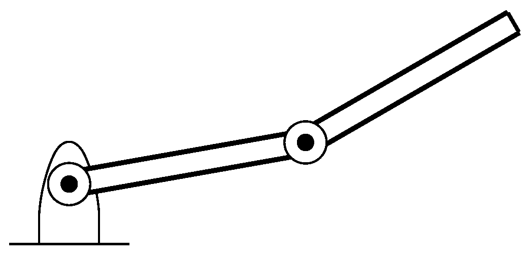
3. Control Algorithm
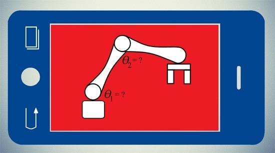
A simple structure of robotic arm having two joints is considered in this work for the performance evaluation of the GPGPU-based independent joint controller as shown in
Figure 1. The proposed scheme can also be extended to other complex robotic structures having multiple joints.
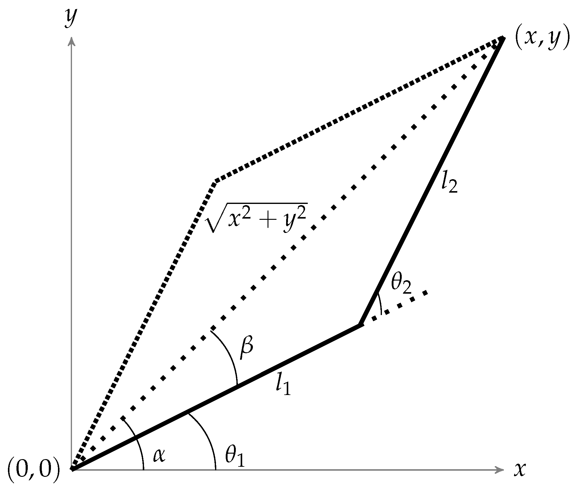
An algorithm is required to rotate these joints to reach to a particular coordinate. For this purpose, the inverse kinematic algorithm is used to represent this robotic arm geometrically as shown in
Figure 2 [
4].
By using basic trigonometric laws (law of cosines etc.), parameters to control the system can be expressed as shown in Equations (
1) and (
2).
where
x and
y are the targets to be reached in Cartesian coordinates and
and
are the angles of the joints to be rotated. Moreover,
and
are the lengths of robotic arms as shown in
Figure 2. It can be noted that excepting the boundaries, there will always be two solutions (the elbow up and elbow down configuration) to reach the required location as shown in
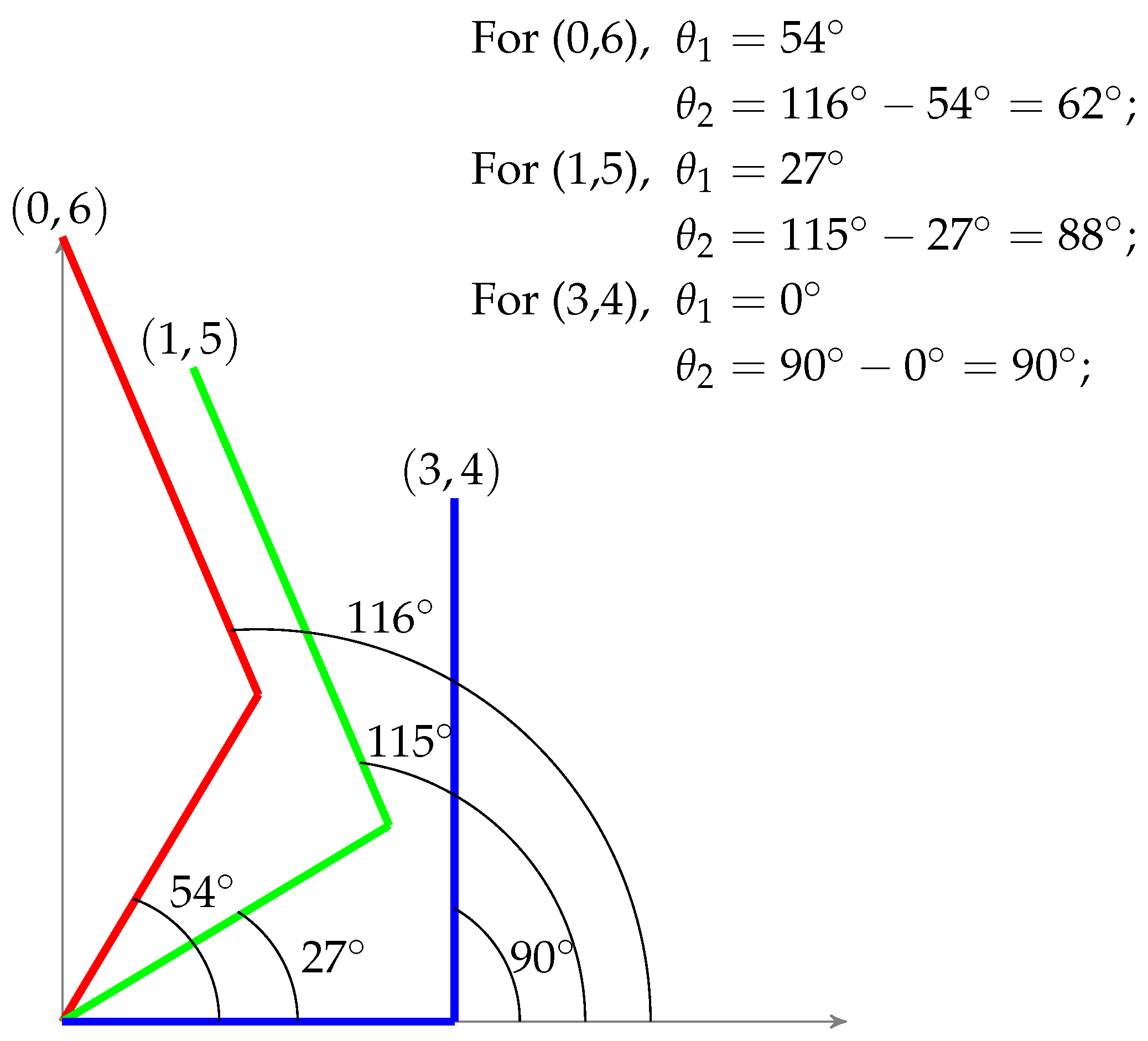
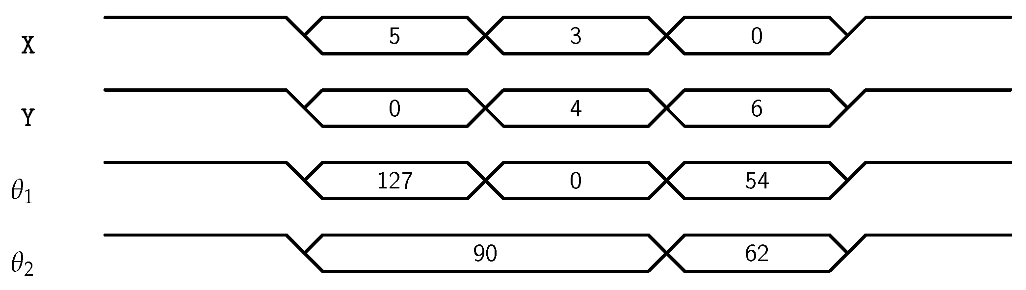
Figure 2, but the controller will choose the one which will be closest to the current position. By doing so, least joint displacement would be required to move to the next point. Moreover, the movement of robotic arm for different test points
,
and
can be visualized by
Figure 3. From the first test point, it can be verified that if
and
are 3 and 4 respectively, and it is required to reach
, then required angles of joints would be 54 and 62 degrees respectively.
The inverse kinematic algorithm discussed in this section is implemented on Arduino-Due, FPGA Spartan-3 and GPGPU Nvidia Quadro K2200 for comparative analysis. Furthermore, this GPU implementation is physically realized by interfacing the mobile GPU with Arduino-Due where computational task is performed by the primary controller (mobile GPU) and movements of motors are controlled by the secondary controller (Arduino-Due).
This research work used the same approach as the multi-axes computer numerical controlled (CNC) machine, where the required product can be designed in computer-aided design/computer-aided manufacturing (CAD/CAM) software using microcomputers. Then, these microcomputers generate the sequential instructions (called G-code) to control the end-effector. Similarly, in this research work, Autocad software is used to draw the design and create the waypoints of the path in the form of cartesian coordinates. These generated points are serially transmitted to the Arduino-Due and FPGA for computation. As it can be imported into the internal memory of mobile device using appropriate file format, it can be used by its embedded GPGPU. These Cartesian coordinates are used by the inverse kinematic algorithm to compute the angles to drive the motors of the robotic arm.
A simple graphical user interface (GUI) can also be developed to design the path or product directly on the mobile device. Control of robotic manipulator using image processing is also an alternative method to mimic the human movements and perform the complex tasks involving the translational and rotational motions. Image processing is a best-suited approach as far as GPUs are concerned where the same operation has to be executed on each and every pixel which can be done efficiently using GPGPUs. An image of a human hand can be captured from the mobile camera and then can be processed using GPGPU to find the waypoints to control the robotic manipulator.
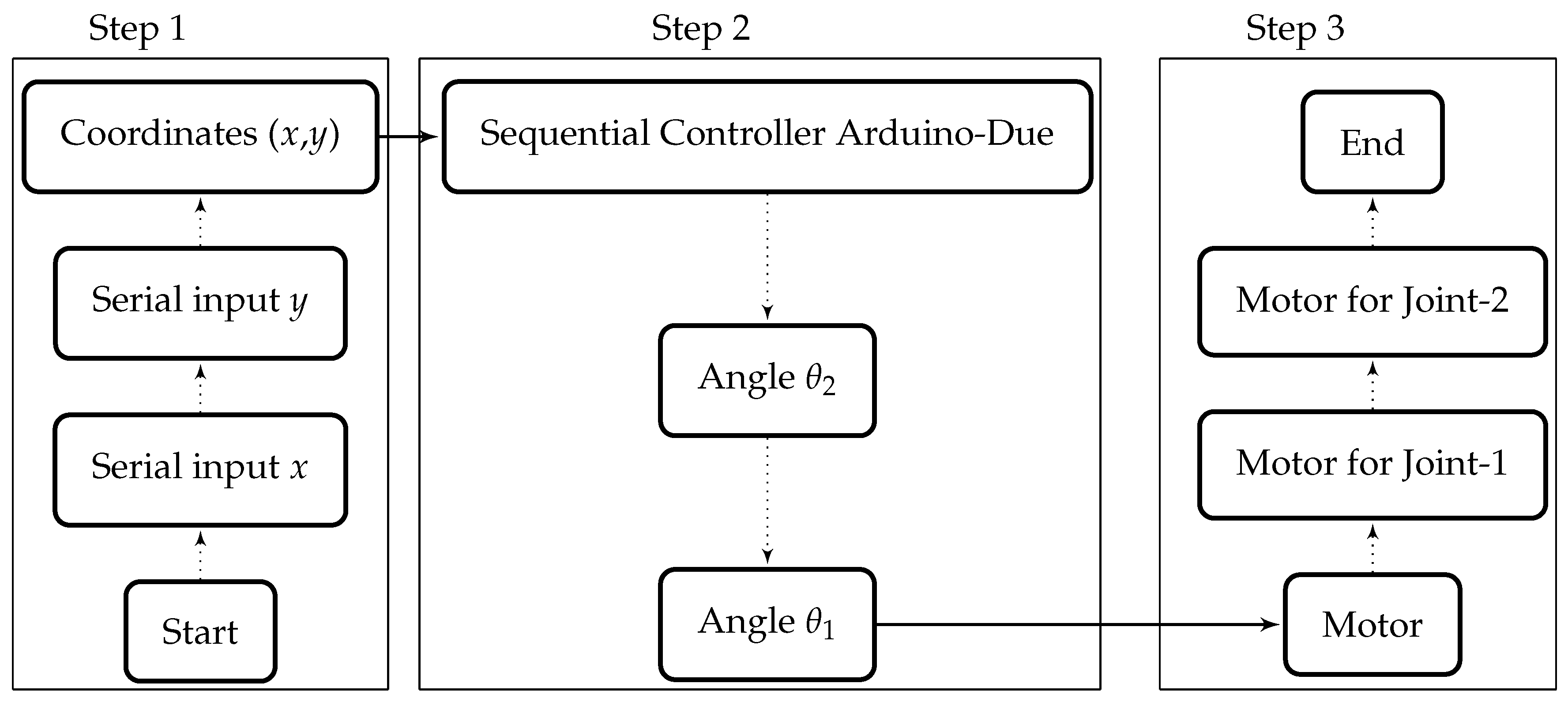
4. Implementation of Algorithm on Sequential Controller (Arduino-Due)
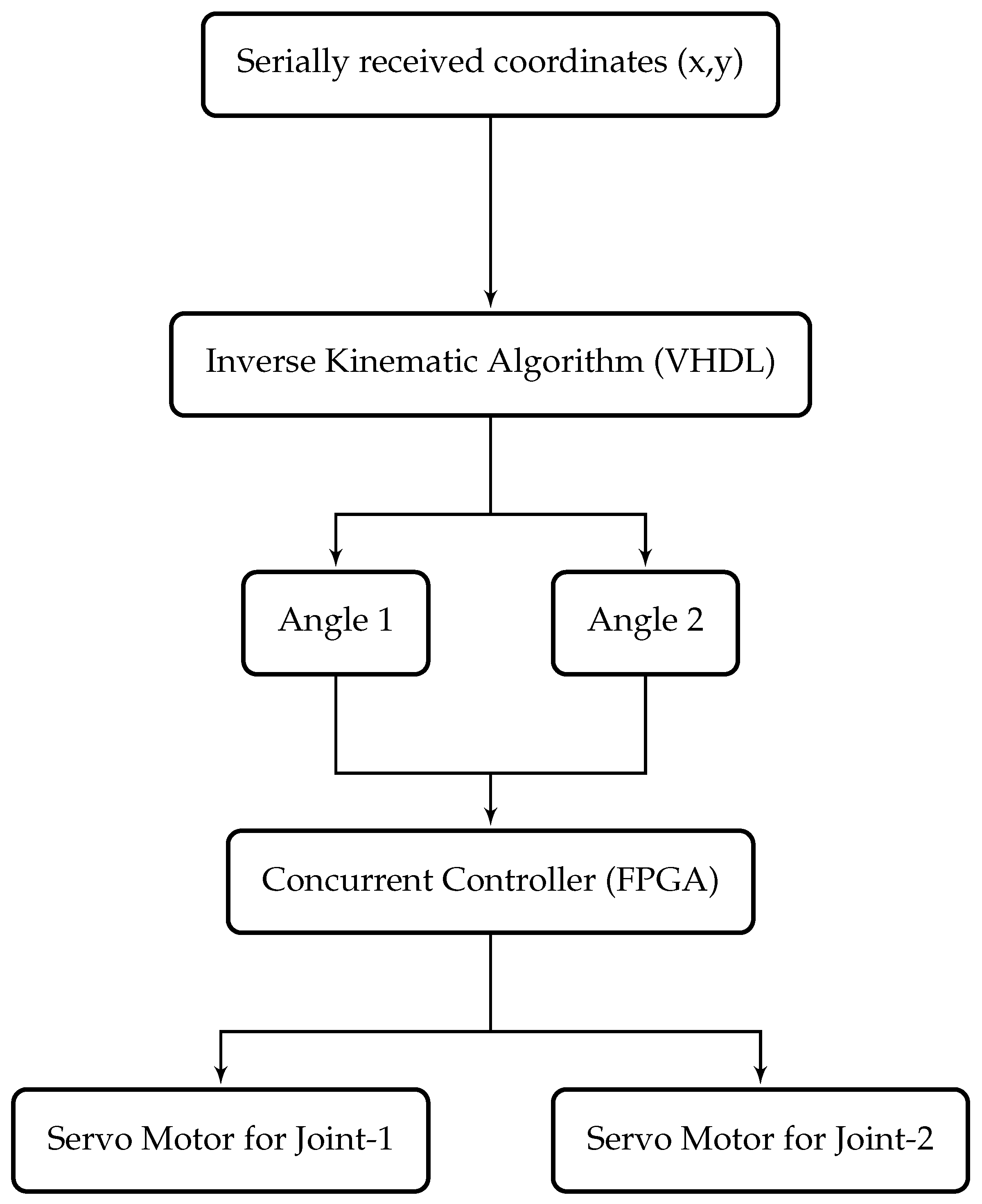
For the sequential implementation of inverse kinematic algorithm, the widely-used powerful microcontroller board Arduino-Due is selected and programmed using C-based language. All the programs and algorithms burned in this controller are executed sequentially as shown in
Figure 4. First of all, the waypoints generated by the CAD/CAM software are serially received by the Arduino. These received coordinates (
x and
y) are used by the microcontroller to compute the angles sequentially, and then signals are sent to the motors of robotic arm accordingly.
Arduino-Due has an Atmel Smart SAM3X8E 32 bits ARM Cortex processor. This is an open source hardware platform, and it has 32-bit core to perform computations on 4 bytes of data in a single clock cycle. It operates at 84 MHz of speed (CPU Clock). Arduino-Due provides support of 54 digital pins for the input and output of digital values. It also has 12 analog inputs pins of 10 bits resolution and 2 analog output pins. Furthermore, it has an universal serial bus (USB) host port to connect the smartphone and other serial devices like keyboard, mouse, etc. The integrated development environment (IDE) is the compiler and burner program for the Arduino Boards. Arduino-Due can be programmed using C language which is sequential. Programming of Arduino is relatively easier because of its large set of software libraries. Therefore, in this work, libraries of Arduino are used for the implementation of inverse kinematic algorithm. Values of coordinates are provided serially by the user as input and computed outputs are the angles of the motors.
In the case of Arduino, there is no built-in performance analyzer in the IDE environment. Therefore, an approach based on stopwatch (micros command) is used to find the execution time of the desired algorithm. This micro command provides the current time of the clock. Consequently, if the performance of an algorithm is to be determined, then it can be placed between the two micros commands and difference of these two outputs would be execution time of the required algorithm. Therefore, the measured average execution time of this inverse kinematic implementation in Arduino-Due is 2 microseconds at 84 MHz of CPU speed.
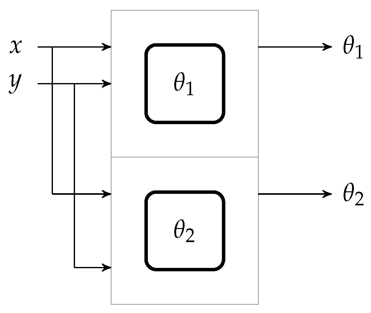
5. Implementation of the Algorithm on the Independent Joint Controller (FPGA)
The FPGA Spartan-3 xc3s200 controller is used for the independent joint computation of inverse kinematic algorithm. Very High Speed Integrated Circuits Hardware Design Language (VHDL) or Verilog Language can be used to program an FPGA. In this work, VHDL is used to implement the inverse kinematic algorithm. The desired algorithm can be divided into smaller tasks and executed faster than a sequential implementation using concurrent processes in VHDL. Concurrent execution capability of VHDL makes it the best choice to execute the algorithms and compute the solution of complex mathematical equations. Moreover, concurrent language can execute multiple blocks of code in parallel. As shown in
Figure 5, both angles of inverse kinematic can be computed in VHDL independently and similarly, control of motors can also be parallelized using FPGA.
The main problem for implementing this algorithm on VHDL is that it does not support the required operations of division. Hence in this work, a combinational divider model is implemented to achieve the required results. This model is discussed in [
35,
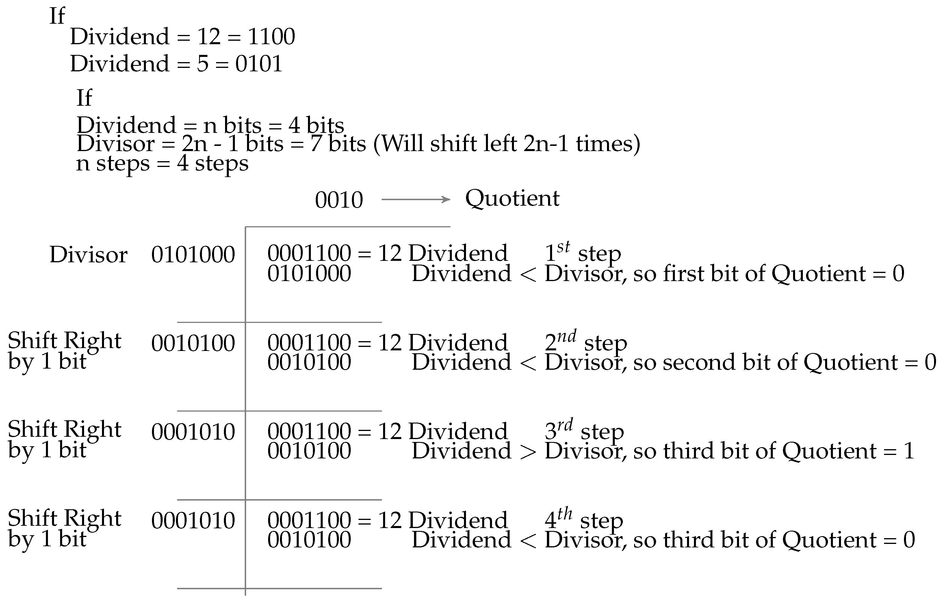
36]. To perform the division operation (quotient = dividend/divisor), a comparison technique is used as shown in
Figure 6.
A shifted version of the divisor is compared with the dividend. Shifting of divisor and number of comparisons are dependent on the lengths of dividend and divisor. If the dividend is less than the divisor then quotient’s most significant bit would be zero and the dividend would be unchanged. However, if the dividend is greater than the divisor then the quotient’s most significant bit would be one and the divisor would be subtracted from the dividend and the new value of dividend would be used for next comparison. Bits computed in comparison would form the value of quotient, and after the last step of comparison, the value of dividend would be the remainder of the division function. A test algorithm is designed in VHDL using this combinational divider and is implemented on FPGA. The result of implementation is verified using the test bench waveform of the system as shown in
Figure 7. This well-known combinational division algorithm is extended to achieve the floating point representation [
37]. The precision of three decimal places is used for computing the inverse trigonometric angles using lookup tables. This representation can be extended to achieve higher accuracy. However, there is also the tendency for a loss of precision as floating representations become very large. This applies in particular to the representations that are derived from very small values (in this case the angles) which can lead to a loss of significance. However, this problem can be resolved by restructuring the mathematical expression.
The complete code is divided into two processes to achieve the concurrency. The first process is for computing the first angle and the second process is for the second angle. These two separate computations are defined through the components in VHDL, where components are the codes that can be called in top module concurrently. After simulation in test bench waveform, next step “synthesis” is performed. Using synthesis, VHDL code is converted into gate level diagram called a Net List. The synthesis report provides some meaningful results like allocated resources and speed of complete implementation.
Moreover, synthesizer generates the register-transfer level (RTL) abstraction of VHDL code. The RTL is a high-level representation of an actual circuit which can be wired on FPGA for hardware implementation. Each RTL block contains entire logic blocks and interconnection of the circuit. The RTL block of the algorithm having two components of
and
can be viewed in
Figure 8.
In the previously discussed controller (Arduino-Due) and language (C/C++), execution time is dependent on the instruction cycles based on CPU speed. Furthermore, the total execution time of a sequential algorithm is that required to take inputs from the user, computing solutions using several instructions having different instruction cycles and then providing the outputs. In VHDL, performance or execution time of implementation is measured through the maximum combinational path delay obtained from the synthesis report. This time is the maximum combinational path delay or execution time after VHDL code is converted to the logic blocks and connections. The path delay and logic area required by the hardware are two important factors to be considered in FPGA. According to synthesis report, for a 50-MHz crystal frequency of FPGA, the maximum combinational path delay for a single test point of the inverse kinematic algorithm is 0.100793 microseconds (100.793 nanoseconds).
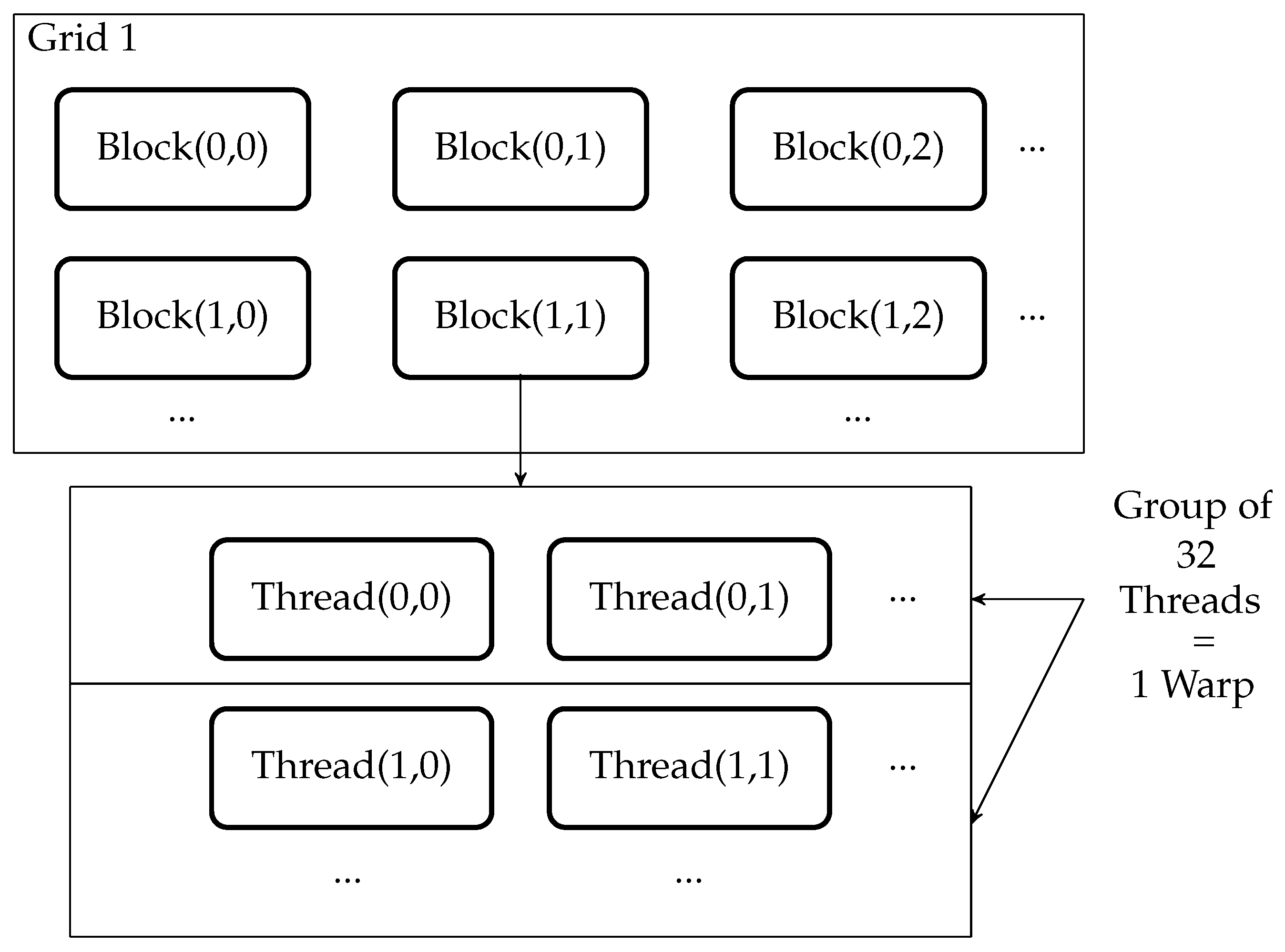
6. Implementation of Algorithm on General Purpose Graphics Processing Unit
GPU is a multicore, multithreaded hardware which can outperform the other embedded controllers using its massive concurrent computational resources. Computing resources of GPU are arranged in multiple grids of completely independent blocks. A single block is composed of multiple threads which can only communicate within their block as shown in
Figure 9. The single instruction multiple threads (SIMT) model of GPGPU is an extension of single instruction, multiple data (SIMD) architecture where the parallel executions are combined with multithreading. In SIMD architecture, the same instruction is executed concurrently for all data. In the SIMT execution model, a set of threads execute the same instruction. These sets of threads are called warps. A warp consists of 32 threads.
CUDA framework enables the graphics processing unit to execute programs designed in C/C++ language [
38]. There are two types of code in GPU programming, host and device code. The host code is used for the configuration of a GPU, allocation of memory and resources, synchronization of events and to issue the command for execution of code on GPU. The device code (Kernel) contains the instructions to be performed on input data [
39].
The inverse kinematic algorithm is implemented using CUDA on Quadro K2200. The execution time of CUDA code is measured using CUDA (event application programming interface (API)) runtime library. Using this CUDA event API, the time between two events can be measured. First of all, the inverse kinematic algorithm is executed using a single thread of GPU. Average execution time of this configuration on GPU is microseconds.
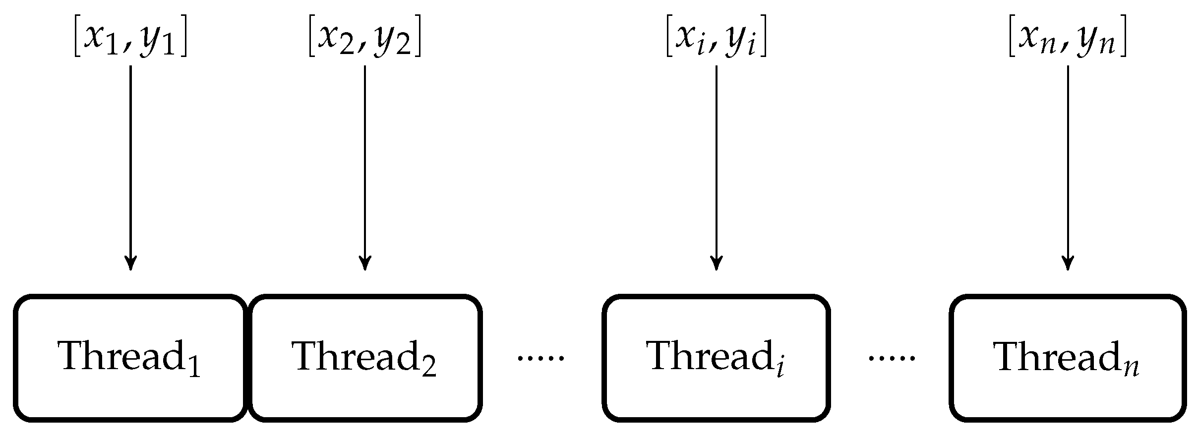
The same code is tested to execute 1000 test points using 1000 parallel threads and GPU calculated the solution of 1000 test points in
microseconds as shown in
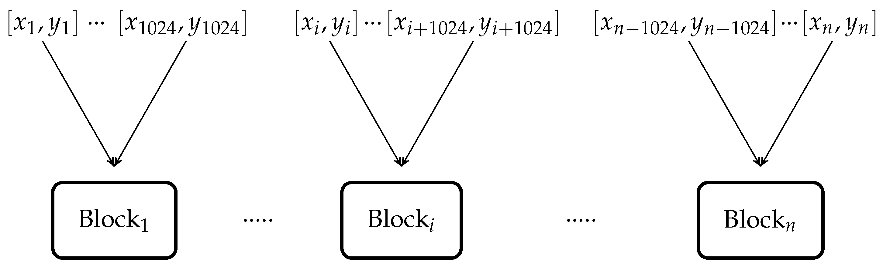
Figure 10. Then, the same code is executed to find the solution of
test points using multiple parallel blocks having parallel threads as shown in
Figure 11.
GPU calculated the solution of
test points in
microseconds using 10 parallel blocks, each having 1024 parallel threads to accelerate the execution. The execution time of discussed configurations of threads and blocks are listed in
Table 1.
7. Comparative Analysis of Embedded Controllers
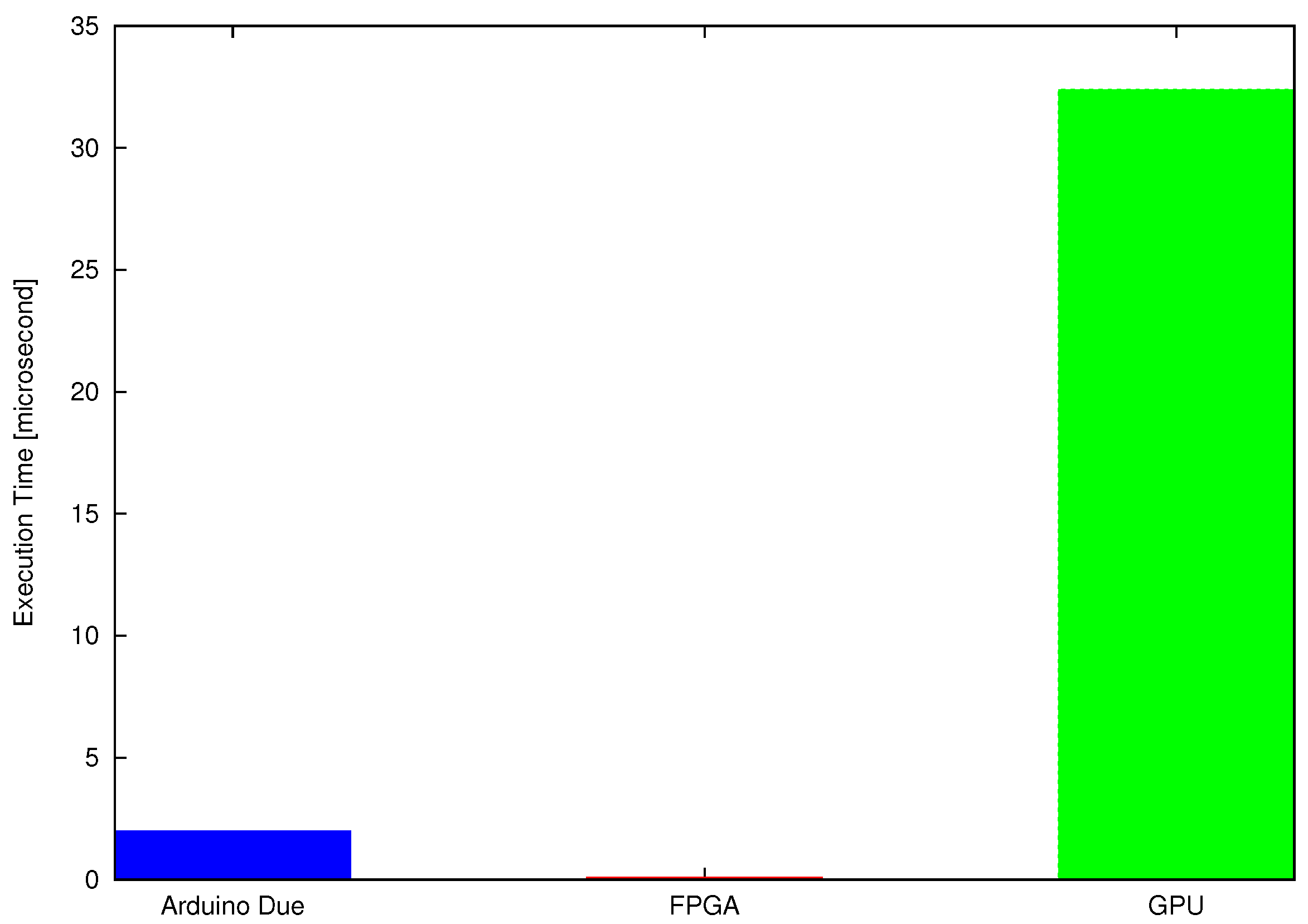
For the inverse kinematic algorithm, the maximum combinational path delay of VHDL code is about microseconds, which is less than the average execution time of the same algorithm on sequential controller Arduino-Due and GPU for a single test point. Arduino-Due (programmed in C) executes the test algorithm in 2 microseconds, whereas the GPU computes the solution of a single test point in microseconds. Therefore, the FPGA is executing codes around tens of times faster than the Arduino-Due and hundreds of times faster than the Quadro K2200 for a single test point.
CUDA implementation for a single test point (using a single thread) is slower than the concurrent implementation of FPGA as shown in
Figure 12. This is because the embedded controllers discussed in previous sections are suitable for single instruction single data (SISD) arithmetic and logical operations while the GPU is suitable for SIMD executions. The GPU can execute required arithmetic operations on a large set of data with higher speed and lower power consumption [
22,
40]. The poor performance of GPU (for a single test point) is because of overhead related to the data transfer and kernel launch. For smaller workload, these delays are significant. Meanwhile, for the larger dataset, achieved performance gain outweighs the transfer and launch overheads.
The task of a robotic manipulator or computer numeric controller is to perform the same operation not just on a single point, but on thousands of defined points or coordinates. The execution time of all discussed controllers would increase linearly with the addition of test points because these controllers are based on SISD architecture where the solution of each test point is computed sequentially. However, GPU can compute the solution of thousands of test points independently using its SIMT architecture.
Figure 13 illustrates the capability of GPGPU to calculate the solution of large data set more efficiently in terms of time.
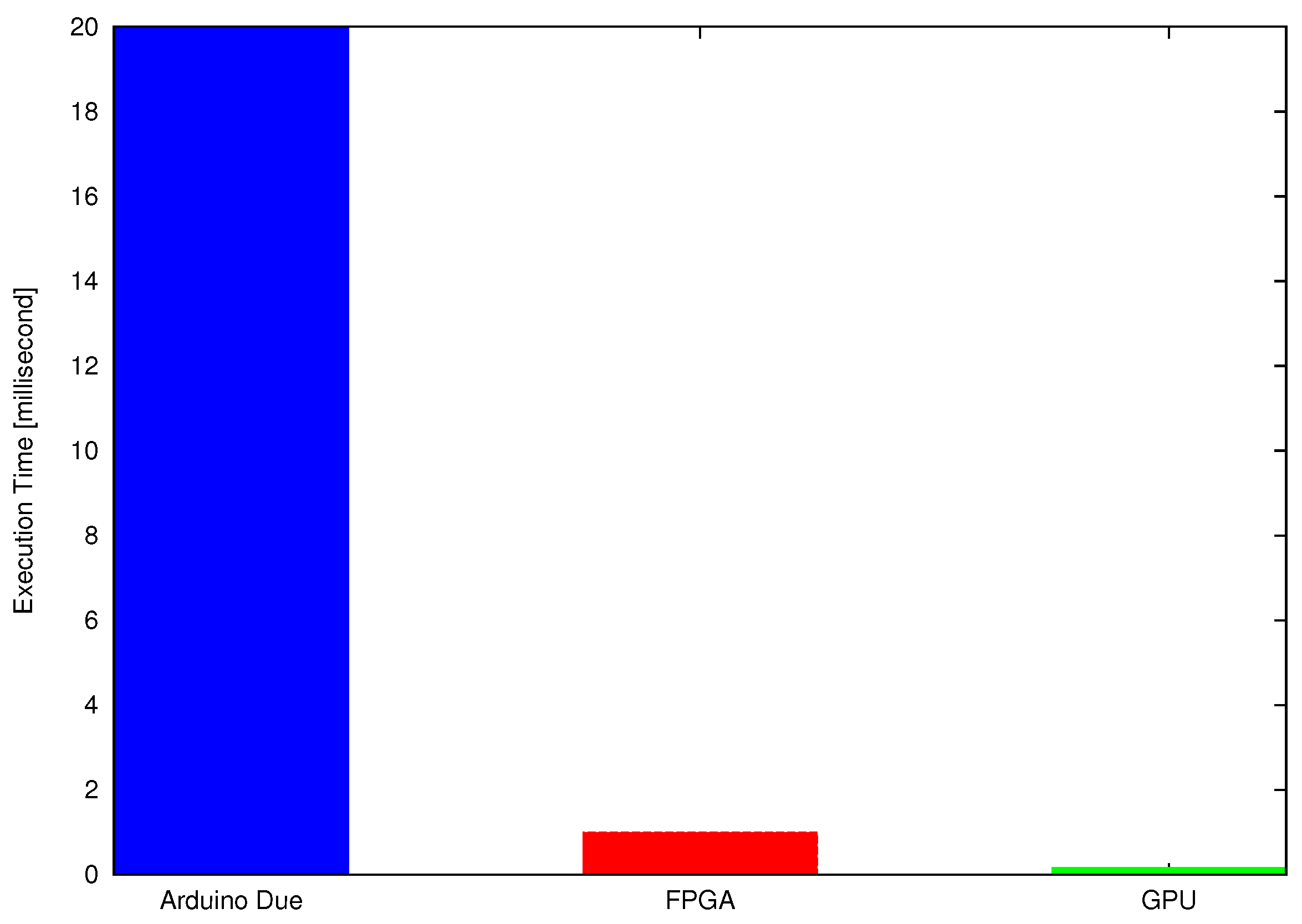
Finally, the performance of discussed embedded controllers is computed and compared under various compute-loads (by changing the numbers of test points) as shown in
Figure 14.
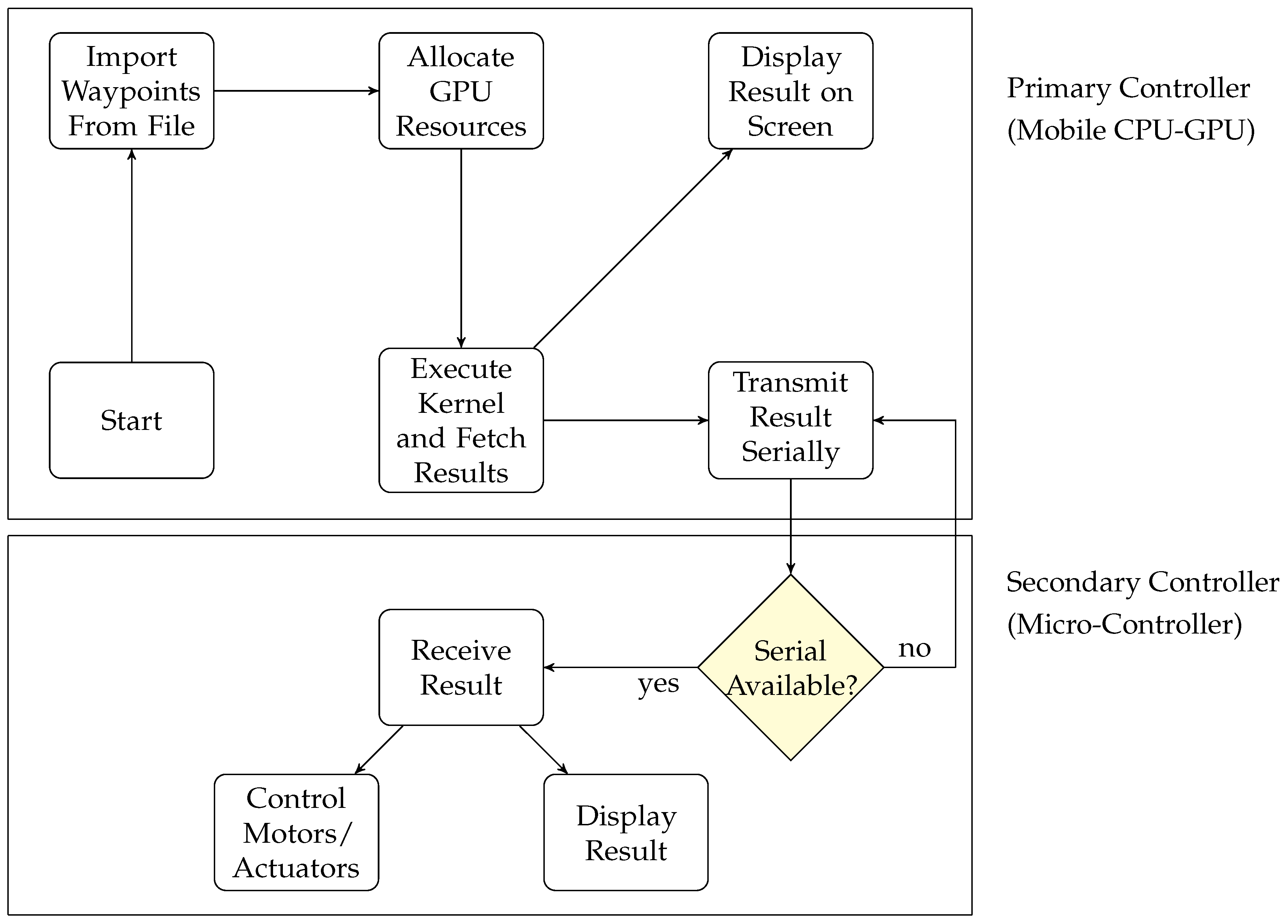
8. Hardware Realization of GPGPU-based Robotic Manipulator
The proposed robotic manipulator is physically realized by interfacing a GPGPU-enabled embedded device with microcontroller where the intensive computations are performed on GPGPU and results are transferred serially to the microcontroller (Arduino-Due) to control the motors of the system. GPGPU computed the solution of the algorithm as primary controller and Arduino-Due controlled the motors as a secondary controller as shown in
Figure 15.
Data to be processed is imported into the mobile platform as a txt file. These test points can be imported from text, mat or bin files in the mobile platform to compute the solution of required data. A CUDA-based inverse kinematic algorithm is executed concurrently using Nvidia Shield K1 Tablet. Nvidia Shield K1 tablet is equipped with a Kepler K1 GPU which has 192 CUDA cores, a quad-core Cortex-A15 CPU of 2.2 GHz and 2 GB of shared random-access memory (RAM). The execution time of all configurations is measured for the mobile platform and is listed in
Table 2. A CPU-only version is also implemented and tested on the mobile platform using Cortex A15 processor. For
test points, a GPGPU-based independent joint controller boasts 40× speedup over the CPU-only reference.
An average execution result shows that the mobile GPGPU gained 5× speedup over the FPGA (Spartan 3)-based concurrent code and is about 100 times faster than the Arduino-Due (having Atmel 32 bits ARM Cortex processor)-based sequential code.
For the realization of proposed system, the serial connection between Nvidia Shield Tablet and Arduino-Due is created using an USB A/B to USB on-the-go (OTG) cable. The Nvidia Shield Tablet has an Android operating system; therefore an Android application is developed to compute the solution of inverse kinematic and make serial communication between embedded devices (GPGPU and Arduino-Due). This serial connection is created using the USB libraries provided by the Android operating system. Since host and device programs are written in C++ and CUDA respectively, it is necessary to use the Java Native Interface (JNI) to call the native function from the Java code. A static library is made from the CUDA code which is link against the Android application.
GK20A is the device name of the Tegra K1 GPU obtained using the CUDA API. The Android application is programmed to continuously monitor the serial connectivity between the tablet and the Arduino microcontroller. As the physical connection is made between the tablet and the Arduino using USB cable, the Android application establishes a serial connection and starts transmitting the computed data ( and in this particular case) to the microcontroller. By changing underlying algorithm and using required sensors and actuators, the same GPGPU mobile platform can be used in various other robotic applications where the execution of large dataset is required to be performed.
Mobile devices are powered by the batteries that are limited in capacity. Nvidia Shield K1 Tablet is powered by a battery of 5192 mAh and 19.75 Wh. A mobile application should be power efficient to maximize the life of a battery.
Table 3 shows that the CPU-based sequential implementation consumes less power due to lower core count, whereas the GPU consumes more power because of its multiple cores.
It can be noted that the CPU-based sequential implementation is slashing the energy consumption by nearly 25 percent but this power consumption is of few milliWatt per hour for both CPU and GPU references which are a small fraction of total available energy for computation of 10,000 test points. However, GPU-based implementation is 40× faster than the CPU-only reference. Moreover, the flow of this GPU based scheme can further be accelerated using optimized data transfer schemes like Unified or Pinned memories.
The proposed scheme can also be extended to other robotic structures with multiple joints like biped robot. The structure of a biped robot is much complex and needs more parameters to be computed. FPGAs are core processing components of such systems [
41]. However, these parameters can be calculated independently using the GPU-based controller and can provide a tremendous speed-up.
9. Conclusions
This paper presents a mobile GPU-based robotic controller for the fast solution of a computationally large and data-intensive inverse kinematic algorithm. The proposed scheme is physically realized by interfacing a GPGPU-enabled embedded device with microcontroller where the intensive computations are performed on a GPGPU and a microcontroller is used to control the motors/actuators of the system. This inverse kinematic algorithm is implemented in widely used sequential and concurrent controllers for the comparative analysis. The proposed GPGPU-based scheme shows substantial improvement in execution speed over other controllers that is needed for a robotic application. Results conclude that the proposed scheme can show promising results in various applications where the computational burden of a numeric controller can be offloaded to a powerful mobile GPU.


