1. Introduction
For many years, there has been an increasing trend of integrating components onto a common hardware platform with different levels of criticality. Criticality is the designation of the level of assurance against failure needed for a system component. Therefore, a mixed-criticality system is referred to as the integration of hardware, Operating System (OS), middleware services and application software of different criticality (e.g., SIL 1-4: Safety integrity level) according to IEC-61508) on the same single embedded computing system [
1]. This concept enables a reduction of the overall number of computers and cables with significant improvements in hardware cost, weight and energy consumption, reliability and scalability competitiveness [
2]. The research field of mixed-criticality systems has therefore received high attention in different areas of embedded systems including operation systems, communication networks and processor architectures [
3].
Mixed-criticality concepts can be applied to many domains like avionics, industrial control, healthcare or the automotive industry [
4], which has a growing need to integrate consumer electronics applications and safety-relevant applications requiring an underlying hard real-time operating system. There are different architectures to provide mixed-criticality. Multicore processors provide significant computational power compared to traditional ones, which makes them an attractive choice for many mixed-criticality systems. In this case, the software execution environments for components of mixed-criticality systems are realized by operating systems and hypervisors with time and space partitioning. The major benefit of using a partitioning approach for mixed-criticality systems is to reduce certification costs in complex systems; this implies that it must be possible to analyse each application in an independent way [
5]. Therefore, the hypervisor has to be certified at the same criticality level as the most critical application; the shared resources have to be allocated to partitions in a predefined and static way; it has to be guaranteed that non-critical applications running in separate partitions do not affect critical partitions; re-certification of a partition should not affect the certification status of other certified partitions. In [
6], a Network Interface (NI) of a network-on-a-chip was proposed in order to establish temporal and spatial partitioning over multicore architectures. The resulting on-chip architecture guarantees predictable timing of time-triggered messages and bounded latencies for rate-constrained messages.
Especially for battery-operated embedded devices, energy saving is vital. In addition, applying power management techniques reduces heat dissipation, which in turn increases the long-term availability and reduces cooling equipment costs. Furthermore, with the help of Low-Power Techniques (LPT), resource use can also be optimised (e.g., by shutting down resources when not used), leading to an overall cost reduction. Even in scenarios where the critical systems are not powered by batteries, power is a resource (together with time and space) that has to be considered for several reasons [
7]:
Reliability: Low power consumption is an important factor to increase the operational reliability and availability in many industrial systems. If power consumption and heat are reduced, the positive impact on reliability is doubled. First, the negative influence on the ageing of hardware elements is lowered, and second, it may avoid the use of cooling systems and mobile parts (e.g., ventilators) in the hardware design. Cooling systems contribute significantly to the probabilities of failure or add additional maintenance intervals.
Availability: A low power consumption allows extending the operation of a system in special situations such as blackouts and energy disruptions.
Ecology: Power consumption reduction is also a desired feature towards near-zero emission in systems with tens/hundreds of electronic control units (ECUs).
Power and energy constraints in mixed-criticality systems have recently gained some attention in the research [
8,
9], but they still have not been applied in an industrial environment. Nevertheless, the application of low-power techniques at different levels (chip-level hardware, system software and at the network level) is very relevant for such systems to optimize their energy consumption. This raises the need for a low-power architecture to enable the development of low-power mixed-criticality systems combined with already available energy-saving approaches such as Dynamic Voltage and Frequency Scaling (DVFS), clock/core gating or power mode switching.
The SAFEPOWER (
http://www.safepower-project.eu) project aims at providing a reference architecture, which demonstrates the applicability of low-power techniques for mixed-criticality systems [
10]. In our previous publications [
2,
10,
11,
12,
13], we have addressed the fulfilment of several indispensable requirements by our suggested SAFEPOWER architecture to enable the usage of low-power management techniques in mixed-criticality systems.
Table 1 depicts our prior contributions and positions our current work with respect to them.
In this article, we claim the following novel contributions:
2. Background and Related Work
2.1. Overview of Low-Power Techniques
In the following, we will briefly review the Low-Power Techniques (LPT) relevant for the experimental section in this article (for more details, cf. [
10,
14]).
Table 2 summarises the main LPT with a targeted power source and possible disadvantages, w.r.t. safety-relevant systems. While frequency scaling targets reducing the dynamic power by lowering the switching activity of the processor, voltage scaling targets both the dynamic and static power by reducing the supply voltage. Both methods have implications concerning the tasks’ execution times, which should be taken into consideration once applied. Clock gating is a special case of frequency scaling, suspending clocks for selected system blocks that are not needed. Similarly, power gating is a special case of voltage scaling to shut off the voltage domains/components that are not in operation with the objective to reduce the leakage power that may have a considerable impact on the overall power consumption. In the latter two LPT, the main consideration is typically the high delays needed to apply such energy-saving methods.
Power management methods are methods utilising a number of LPT to achieve energy consumption reduction of the underlying hardware. Dynamic Power Management (DPM) (also called Power Mode Management (PMM)) [
15] supports different low-power modes (e.g., idle, sleep, stand-by). At runtime and based on the system state, the switching between different modes is done, where in each mode, different energy budgets and response times are needed.
Monitoring the current system status including the temperature, current and voltage of the system is vital to assure that the LPT has been applied successfully and safely. For this, we used board-specific monitoring devices such as voltage regulators and temperature sensors (
I2C/PMBus devices), On-chip firmware devices (e.g., [
16,
17]) and
analogue-to-digital converters.
2.2. Impact on Safety
Low-power techniques, such as the ones described above, have not been extensively used in the computing domain of safety-critical applications. Classic safety-critical systems used to have an “unlimited” source of power supply, and their approach was federated, one application-one hardware platform, so this power supply was not shared. With the increasing proliferation of battery-powered systems (e.g., in transport) and the higher demand of more functionality in the hardware platform, the new scenario demands more power-efficient computing platforms also for safety-critical applications, where this hardware is centralized in inherently more power hungry and complex platforms (e.g., heterogeneous and multicore SoCs). Therefore, the focus of the research is on how those low-power techniques may impact the functional safety at the system level (e.g., not in the microelectronics reliability, as other works correlated power and temperature with soft-errors rates [
18]). From this overall safety perspective, this carries the following challenges:
The impact on timing of the low-power techniques should be predictable and reproducible: both the execution time of the LPT (since they are requested to support their effective implementation) and their impact on the system timing (e.g., frequency scaling) have to be known a priori and verified in a static manner. The safety of the system stands on its timely response; for instance, a late red light on a signalling system or a delayed brake on any transport system could have catastrophic effects.
Low-power techniques should not break the temporal and spatial isolation of mixed-criticality systems: safety-critical applications share computing resources, and the mapping of the sharing of these resources is typically guaranteed by an embedded hypervisor. Low-power techniques are often shared by all the resources (e.g., frequency scaling applies to all cores), and the requests to their applications should be controlled in such a way that a non-critical application cannot change the behaviour of a critical one.
2.3. Safety Standards
Within the SAFEPOWER architecture, the use of LPT has been aligned with safety standard recommendations when addressing the challenges described in the previous section, specifically with the reference standard for embedded electronics safety-related systems IEC-61508.
The IEC-61508 (
Section 3 Annex F.5) requires achieving temporal independence between software elements hosted on a single computer system, and it recommends deterministic scheduling techniques, like time-triggered architectures or time slice approaches supported by worst case execution time analysis, to demonstrate statically that timing requirements for each element are met. Thus, static resource allocation is highly recommended over dynamic reconfiguration (
Section 3 Annex A.2).
Aligned with this safety standard requirement, the SAFEPOWER architecture relies on the static planning of the LPT based on system modes (or low-power modes). LPT are activated only within predefined modes, for which the timing behaviour has been statically assessed. Additionally, mode transition is justified using “graceful degradation” (
Section 3 Annex A.2) by dropping less critical functions, which is a highly recommended technique by the safety standard. At runtime, only the switching between predefined modes is managed, which is the responsibility of the hypervisor within the SAFEPOWER architecture.
3. The SAFEPOWER Reference Architecture
3.1. Overview
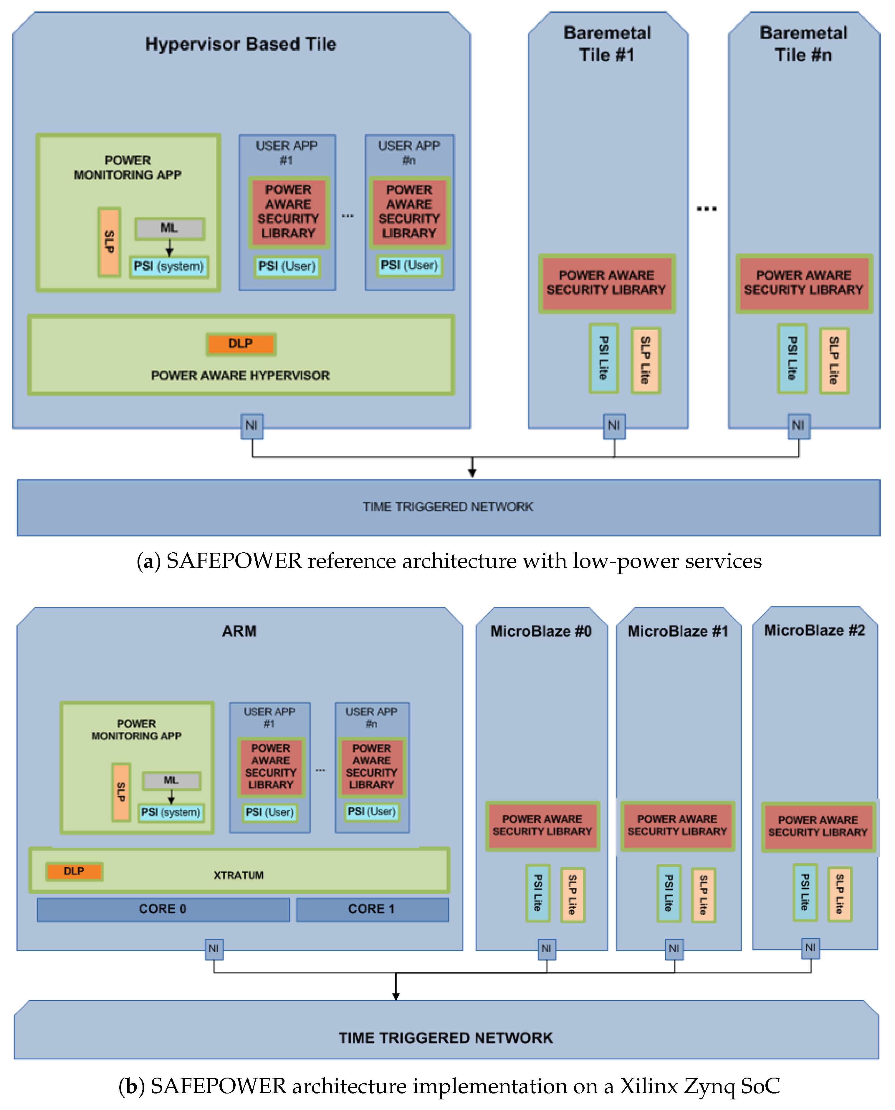
The SAFEPOWER reference architecture (see
Figure 1a) consists of a tile-based architecture, which is connected via a time-triggered network on chip. The tiles can contain various processors and peripherals. Tiles can be managed by a Type-1 hypervisor [
13] running on the tile’s hardware and allowing for an arbitrary amount of user partitions. The hypervisor provides a monitoring partition to which dedicated hardware monitors are connected. The monitoring partition can poll the monitored values and enables the hypervisor to react to system changes.
To reduce the complexity, unmanaged tiles, also called bare-metal tiles, are not organized by a hypervisor. To establish a transparent view on the system for applications, the unmanaged tiles implement a light version of the hypervisor application interface. This way, applications can be mapped to different tiles without extra effort. Each tile is connected via an NI to a time-triggered NoC. The time-triggered behaviour is executed based on a pre-computed communication schedule that triggers the message injection times.
The SAFEPOWER reference platform has been defined with enough abstraction level so that it can be implemented regardless of the platform or any other details like the hypervisor used in a multicore platform or the communication used among processors. An example implementation for the Xilinx Zynq SoC can be seen in
Figure 1b. Besides the single tiles and the time-triggered network, the main components of the suggested architecture (shown in
Figure 1a) are described in brief below. For more a detailed description, please refer to [
19].
Extended Hypervisor (DynamicLPT)
This is an extended version of a hypervisor (see [
13]) that integrates a subset of LPT, named “DynamicLPT”. These techniques take advantage of the dynamic slack time of the running application, i.e., the idle time since a partition completed a periodic task until the next start of the task itself. These techniques allow the hypervisor to implement scheduling plans that take advantage of the dynamic behaviour of the running application. For example, the system frequency can be automatically reduced, or a core suspended, if a slack time over a platform-specific threshold is detected in a running task.
Static Low-Power Block (SLP)
This software component placed outside the hypervisor system software includes the static LPT (peripherals suspension or voltage scaling) that do not affect the hypervisor behaviour by interfering in the temporal and spatial isolation of the partitions. For instance, the voltage scaling LPT is implemented within SLP because, usually, it implies a few millisecond delay that would break the temporal isolation. This timing overhead is introduced by the communication interface (for, e.g., the PMBus: Power Management Bus) interface) used to communicate with the external PCB power management devices.
Static Low-Power Lite Block (SLPLite)
This software component is similar to the previously-explained LPT, but it does not depend on a hypervisor, and normally, a reduced set of low-power techniques is supported depending on the processing elements within the unmanned tile (e.g., only clock-gating and frequency scaling).
Power Services Interface (PSI)
This is the API that is used by the application developers to enhance their software with power-aware services. This interface provides the monitoring services and the entry point to the use of the DynamicLPT integrated in the hypervisor. For instance, the partitions will be able to receive information about power consumption, and the “TASK FINISHED” service enables the hypervisor to suspend the core during partition idle times.
Power Services Interface (PSI Lite)
As with SLP Lite, this is a reduced PSI API that is used by the application developers to include power awareness. This interface does not depend on a hypervisor.
Low-Power Monitoring Partition (Monitoring Partition)
This special partition runs on the hypervisor with special system rights. It is one of the main components of the architecture. Its main function is to monitor the power consumption by accessing the sensors and by providing the measurement results to the other partitions and tiles via the mentioned PSI. The secondary function is to apply the local static LPT via SLP. Complex power management services will be centralised only on this partition to ensure that other partitions and tiles do not interfere with each other by accidentally applying LPT in critical circumstances. This decision implies that the monitoring partition should have application-specific information to know when to apply which power reduction services.
Power-aware Security library
This security library supports the implementation of security protocols (WolfSSL/TLS and Poly1305-MAC code) for messages being transported from the SAFEPOWER board to the environment (e.g., via Ethernet).
3.2. Implementation
This section describes the actual implementation of the SAFEPOWER architecture for a specific processor (Zynq-7000 SoC with three MicroBlaze processors on the programmable logic part), hypervisor (XtratuM) and communication network (time-triggered extension layer over Nostrum network-on-chip).
The XtratuM hypervisor has been modified to instantiate the architecture proposed before (see [
13] for more details). The mapping was straightforward: the PSI has been renamed as the extended Dreams Abstraction Layer (xDRAL) and the low-power monitoring partition as the monitoring partition. XtratuM already supported the ARM Cortex A9 processor, so it was decided to use the processing system of a Xilinx Zynq-7000 SoC. XtratuM has been extended in the monitoring partition with the monitoring services that collect information from the external devices of the SAFEPOWER board (highly-instrumented board based on Zynq-7000 SoC) and the Xilinx Analog-to-Digital Converter (XADC) of the Zynq.
The LPT integrated were those ones supported by the SAFEPOWER board. Frequency scaling, Double-data-rate (DDR) memory suspension and core suspension (power gating) were the DynamicLPT implemented. The included static LPT (SLP library) were the voltage scaling and programmable logic power gating.
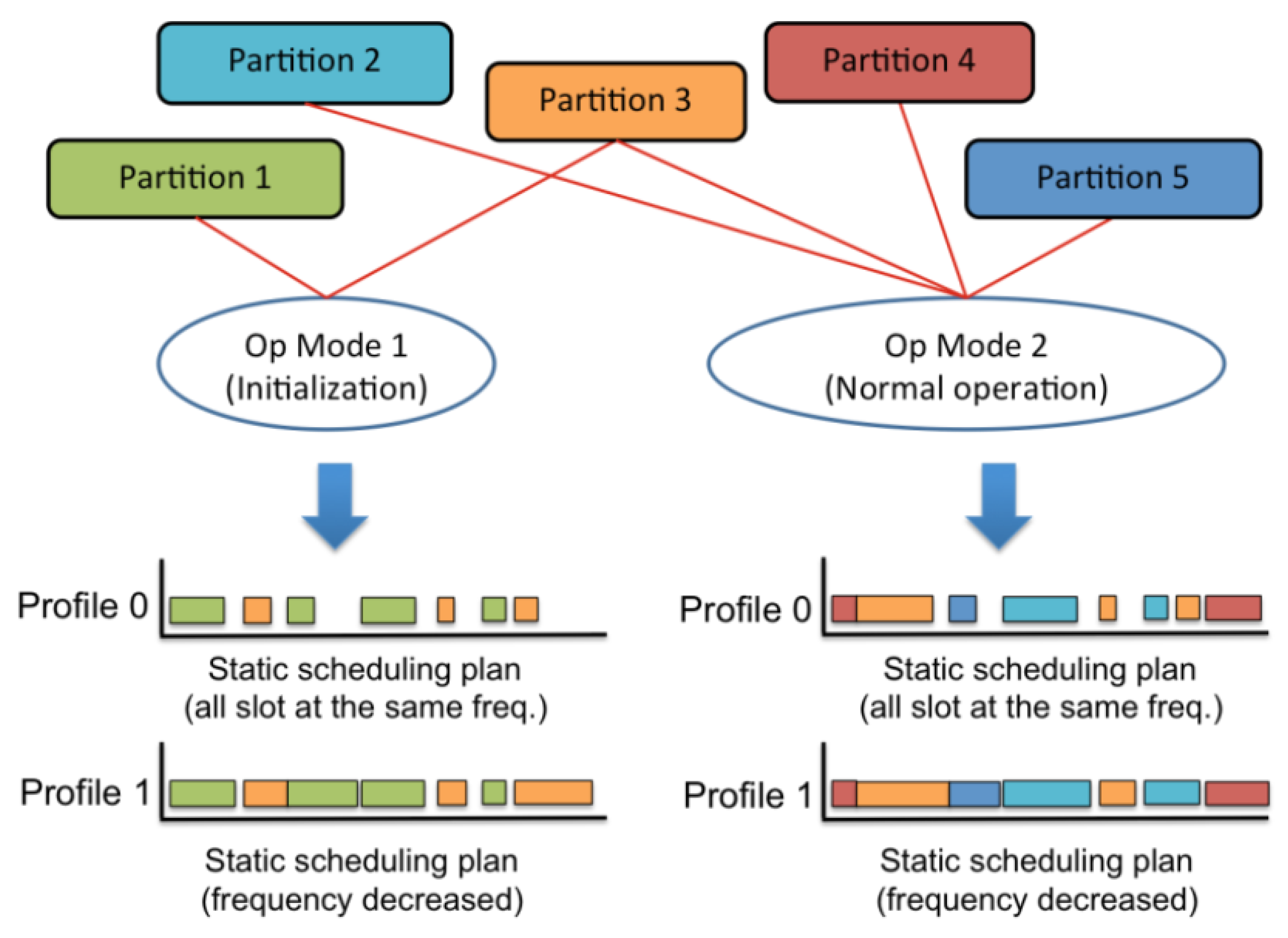
Moreover, a tool, called Xoncrete, has been implemented to ease the inclusion of power mode management. It automatically creates different scheduling plans, six low-power profiles, based on the concept of frequency scaling and the input provided by the designer regarding worst case execution time and criticality of the partition. Criticality definition was required because in some cases, the energy saving will be done at the expense of a performance loss, like halting a partition. Based on the criteria defined during the architecture description, switching between different low-power profiles or schedules precomputed during the design phase was initiated by the monitoring partition.
Figure 2 shows a simple example in which an additional scheduling plan (Profile 1) is generated for each operational mode. This new plan executes partitions at different frequencies, so it saves energy with respect to the original plan (Profile 0) in which all partitions run at the highest frequency.
The SLP and xDRAL functionality were also implemented in SLPLite and xDRALLite for the MicroBlaze processors. xDRALLite was able to provide monitoring services, as well as a communication interface to use the time-triggered network-on-chip (TTEL). The LPT included in the xDRALLite implementation were clock-gating and frequency scaling.
4. SAFEPOWER Virtual Hardware Platform
The virtual platform was created using processor and peripheral model libraries from the Open Virtual Platforms (OVP) resources (
www.ovpworld.org) and the simulation and analysis technologies from Imperas Software Ltd (
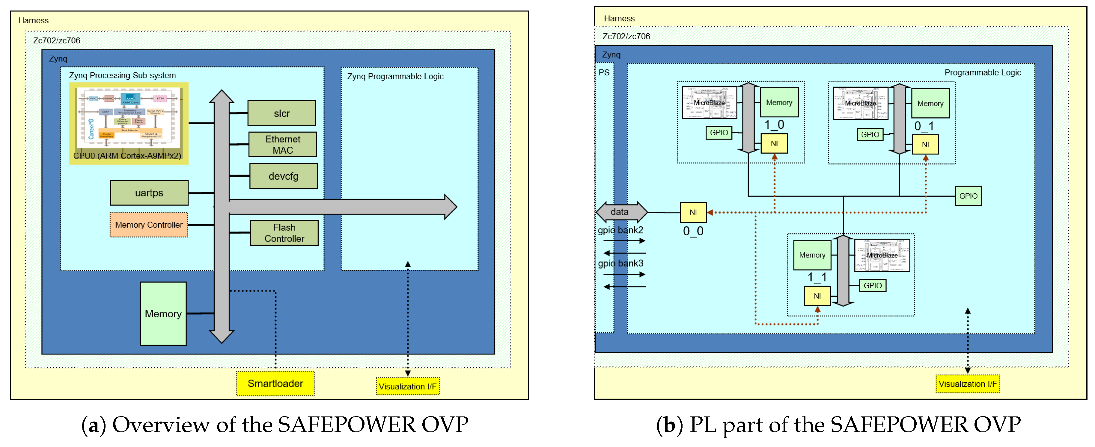
www.imperas.com). OVP provides the simulation and modelling infrastructure, and Imperas provides additional technology and tools that utilize the virtual platform to allow software analysis for timing and power estimation. The resulting virtual platform was a programmers’ view representation of the target hardware that permitted additional debugging and analysis to be performed without modification to the software under test. The SAFEPOWER OVP virtual platform depicted in
Figure 3a provided functional models of the SAFEPOWER architecture (see
Figure 1) implemented (without loss of generality) for Xilinx Zynq development boards. It included an ARM Cortex-A9MPx2 processor core and other peripheral devices as part of the fixed Processing System (PS) and the ability to load definitions for the Programmable Logic (PL). The PL (see
Figure 3b), as used, contained network-on-chip communication with interfaces matching that of the hardware devices and connected three sub-systems, each containing a MicroBlaze processor, memory and peripheral devices. The virtual platform also realized the Power Monitoring (PM) devices that could be accessed by software to obtain the current state of the environment. The PM device registers, read by the software that controlled the operations of the system, were updated by a Power Interface Library (PoIL), implemented using Imperas technology, that monitored the execution within the virtual platform and calculated the power and temperature values for these devices.
The SAFEPOWER OVP is capable of executing the same application binaries that are executed on the physical hardware and so can be utilized in the test and certification of safety-critical applications without modifications of the software under test. In addition, SAFEPOWER OVP provides many benefits over the use of hardware for the development, debugging, analysis and verification of software applications. These include, but are not limited to:
Execution control: This is the deterministic simulation and full control of all processing elements. In the scope of the SAFEPOWER project, this was extended to support the simulation of time-triggered schedules (see [
12]).
Unified debug environment: This allows the simultaneous debugging of all application code executing on the processors in conjunction with access to the peripheral models (programmers view and behaviour) and shared resources, for example memory. With the help of analysis tools, a designer can analyse the execution and provide profiling, code coverage, dynamic assertions, etc., without the need to modify the applications’ binary code. On top of this feature, an approach was implemented in the scope of the SAFEPOWER project to validate the functionality of the low-power management techniques (see [
11]).
Fault injection: The virtual platform resources are accessible, so faults can be injected into any part; for example, modifications can be made to memory, processor registers, interrupt or reset lines and other resources. These can be automatically generated as required, for example on events or after a specific execution time.
5. Evaluation
The SAFEPOWER architecture implementation has been integrated in two Use Cases (UC) from different domains: railway and avionics. In the following, we will describe each case study, the evaluation setup and the results obtained focusing on the low-power features of the SAFEPOWER architecture. Despite the difference between the two industrial use cases, they followed the same evaluation scheme. Both will evaluate the functionality and basic timing with and without low-power techniques on both the virtual platform and the hardware PCB platform. Both the virtual branch and the hardware branch compare the effect on the low-power functionality, the change/issues in timing within partitions/applications and power savings when running without and with low-power techniques. The main objectives are:
Demonstrate that the software components interact correctly with each other and with the hardware to carry out the functions for which they were designed,
Verify that the entire system complies with the requirements—functional and extra-functional, also when including sessions with low-power techniques—of the requirements’ specification,
Show that power savings can be reached for safety-critical applications in different domains.
5.1. Railway Case Study
5.1.1. Railway Application Description
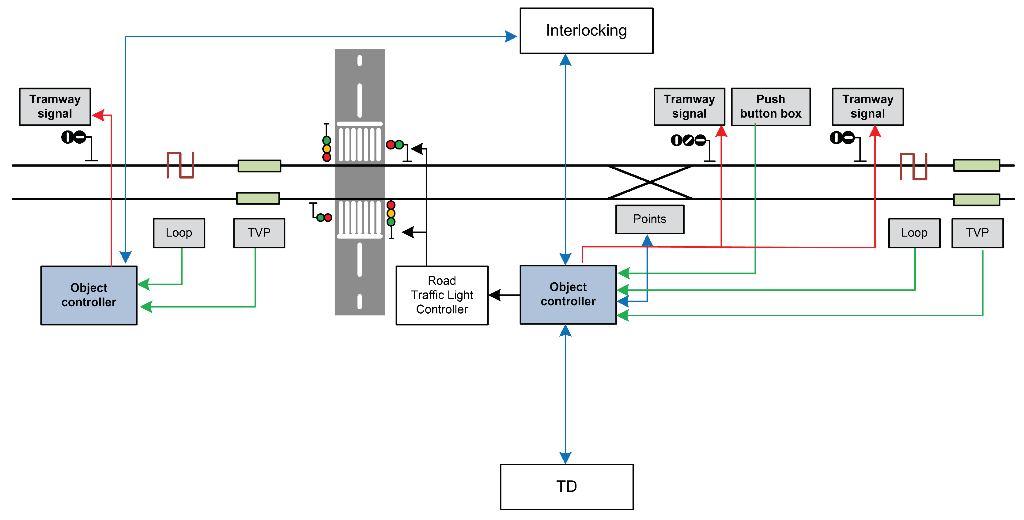
Electronic interlocking is responsible for controlling the track-side field elements directly connected to it. Large installations need to decentralize the interlocking operation using a large number of object controllers, each one close to the field elements it controls. An object controller receives commands from the interlocking, applies these orders to the field elements and supervises the field elements controlled by itself. It also stores events and alarms that occur during the processing period and sends this information to the maintenance system.
The railway use case is working on an innovative highly-autonomous object controller that needs to operate with limited energy and guarantees a high availability, allowing the object controller to work with no need for any wiring between it and the central interlocking.
Figure 4 shows a simplified diagram of the elements that communicate with the object controller. The object controller performs functions with different levels of criticality regarding the parameters of the safety, security, reliability, availability and maintainability of a SIL-4 system. For instance, some functions are safety-critical, and others are not, but the system must show a high level of reliability and security. Therefore, the implementation of this use case is based on the mixed-criticality architecture proposed by SAFEPOWER (see
Figure 1). The object controller was implemented on the virtual platform and the real hardware. platform.
The competitive advantages of the object controller based on the SAFEPOWER architecture are summarized below:
System scalability due to the decentralized operation.
System modularity due to autonomous power supply and low-power consumption technologies,
Deployment and maintainability cost reduction due to less wiring.
5.1.2. Mapping Railway UC to the SAFEPOWER Reference Architecture
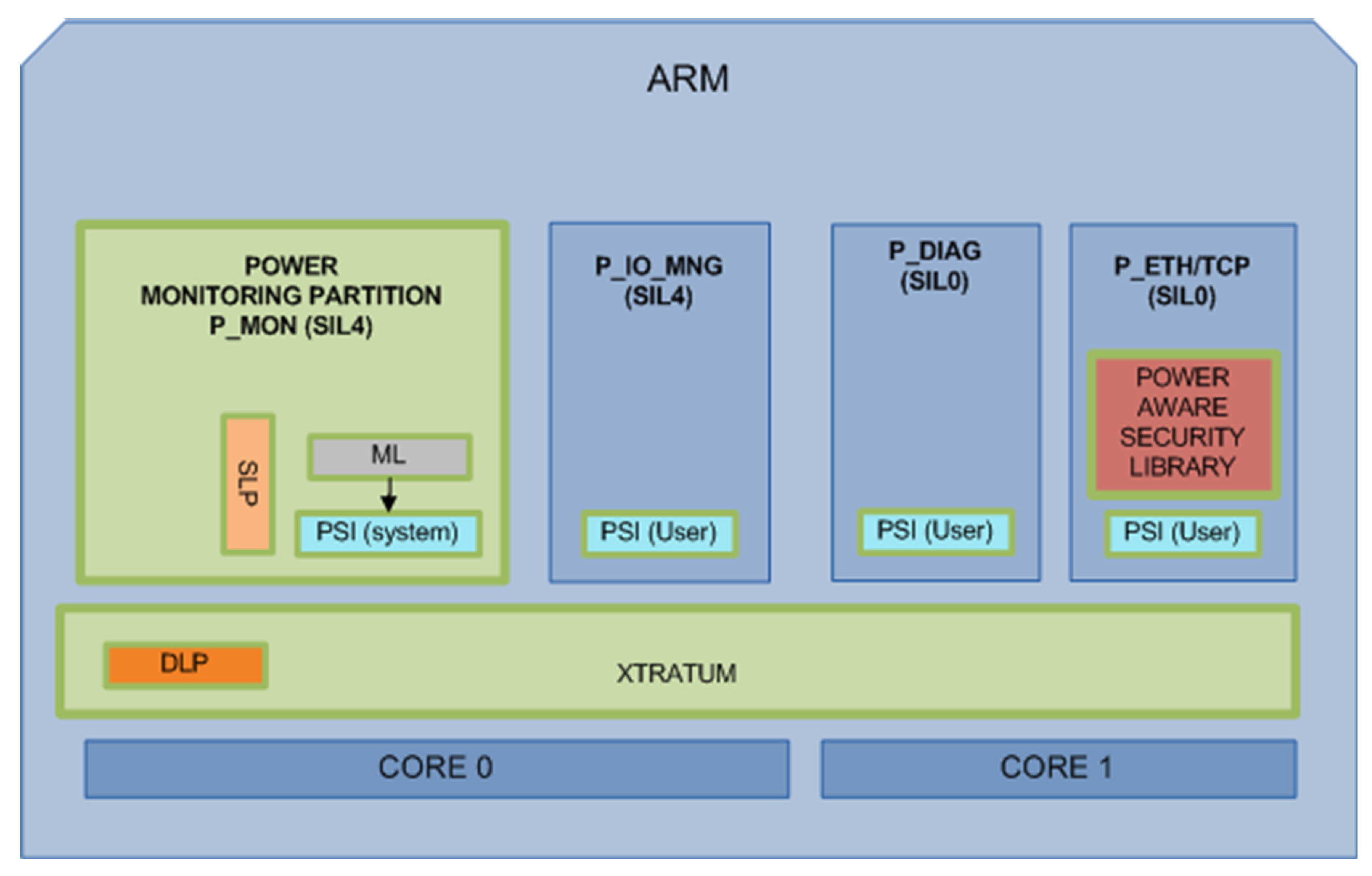
Figure 5 shows the mapping of the railway use case to the SAFEPOWER reference architecture and the components implemented. The object controller processes the field elements information as digital input/output information and sends it to the interlocking. The interlocking knows the field topology. The object controller also exchanges information with the diagnostic and maintenance system. The object controller stores each event and alarm that occurs during processing to allow for post-processing by the diagnostic and maintenance system.
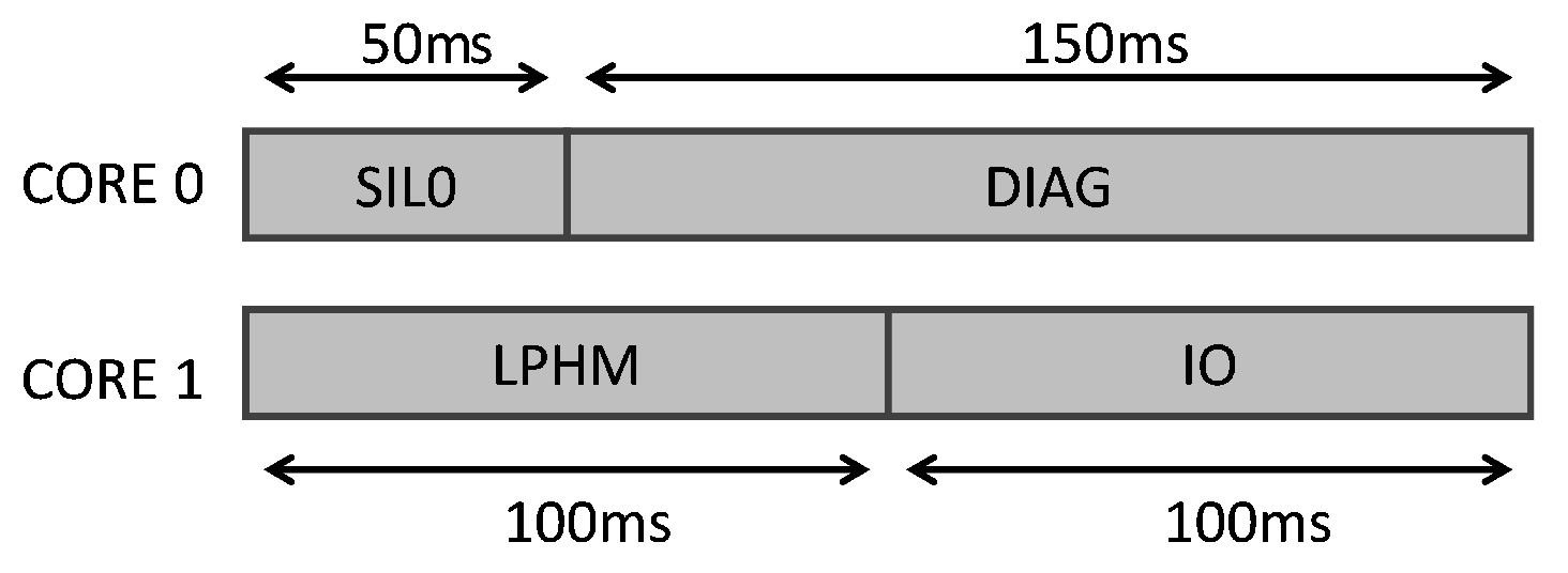
The railway UC defines four partitions with different criticality levels. These partitions run in the Processing System (PS) of the Zynq SoC (see the periodic time-triggered schedule in
Figure 6) over XtratuM (see
Figure 5), which guarantees a robust partitioned environment:
P_MON: Power Monitoring Partition (SIL4),
P_IO_MNG: Input/Output Management Partition (SIL4),
P_ETH/TCP: Ethernet, TCP and security library Partition (SIL0)
P_DIAG: Diagnosis Partition (SIL0)
5.1.3. Railway UC Evaluation Setup
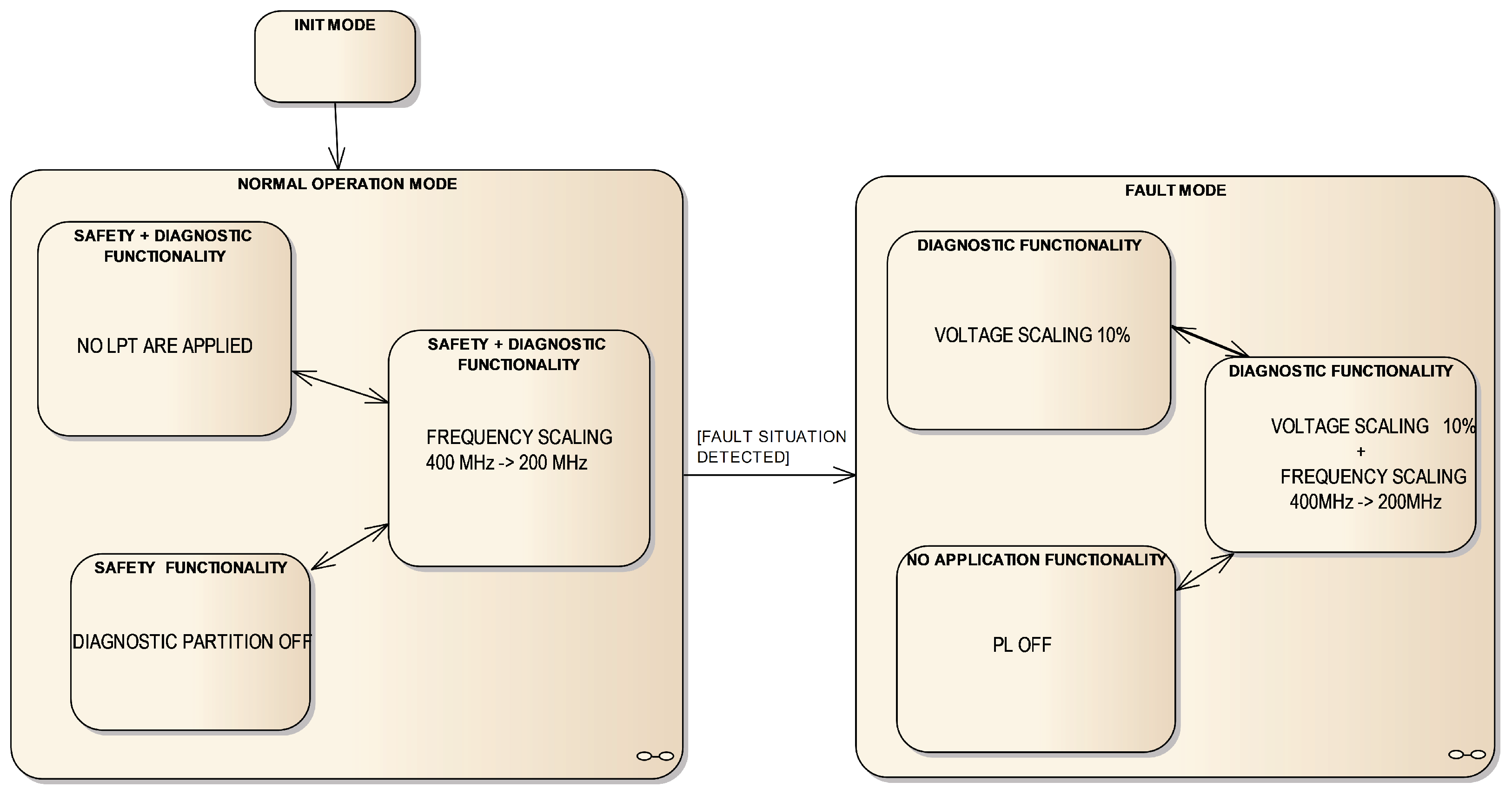
The railway UC tests were executed according to the operation state machine depicted in
Figure 7), where low-power techniques are allocated as follows:
In Normalmode, the safety functionality is executed:
In Normal/Normal mode, no LPT is applied.
In Normal/Trimmed mode, frequency scaling from 400 MHz–200 MHz is applied.
In Normal/Dropped mode, Diagnostic Partition (P_DIAG) is switched off, setting the processor to idle instead.
In Fault mode, the safety functionality is not running due to a fault situation having been detected:
In Fault/Normal mode, voltage scaling is applied to the PS part from 1 V–0.9 V.
In Fault/Trimmed mode, frequency and voltage scaling are applied.
In Fault/Dropped mode, PL is switched off. There is no railway functionality in this mode, but monitoring is working normally.
Transition between the two modes is triggered depending on the temperature and power consumption measurements.
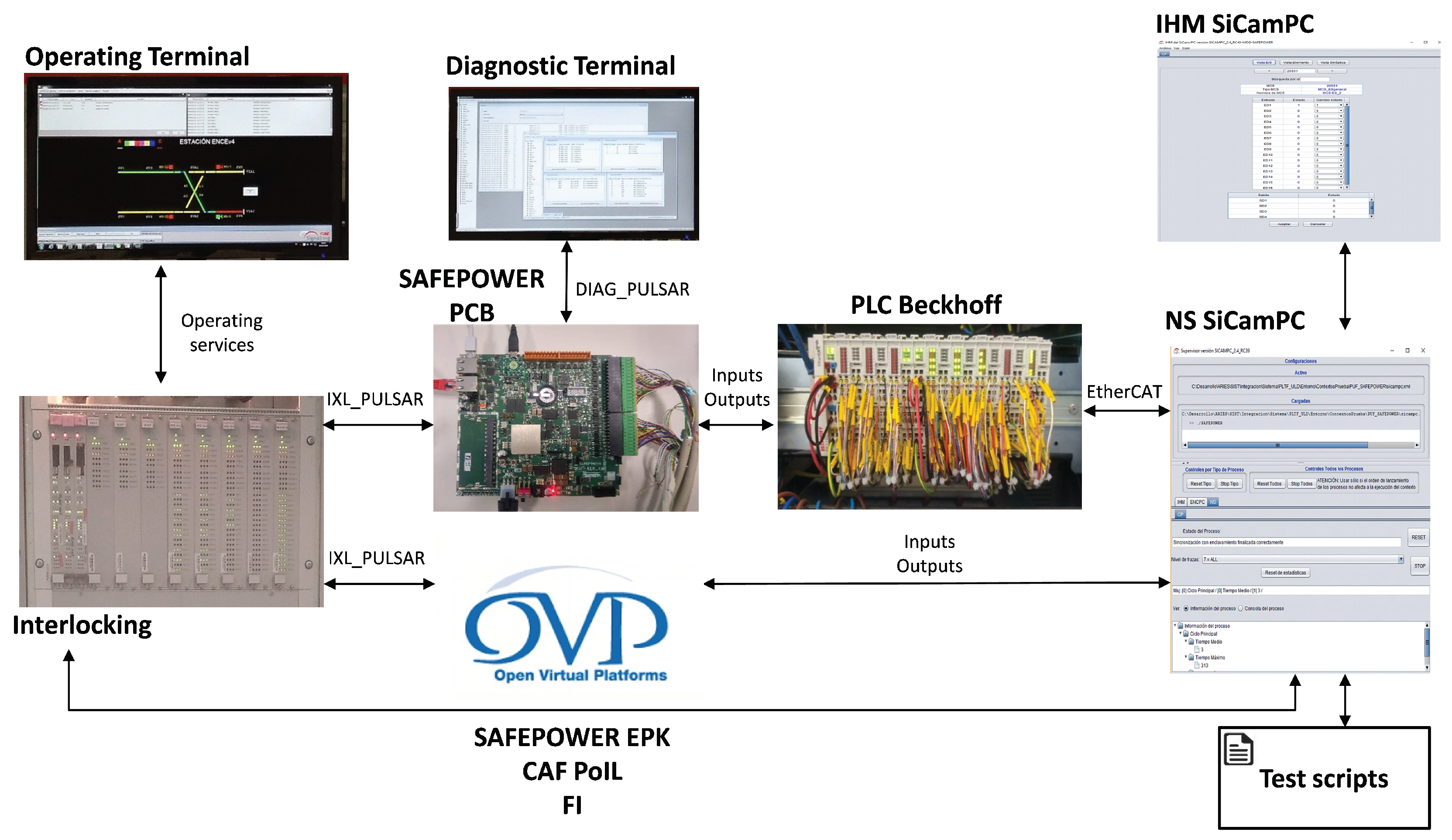
To perform the intended tests on the SAFEPOWER hardware (PCB), the validation environment (see the top part of
Figure 8) with the following components has been developed:
SAFEPOWER PCB: runs the object controller application.
Interlocking: communicates with the object controller, giving orders and receiving the inputs’ state.
Operating terminal: represents the state of the field elements controlled by the interlocking.
Diagnostic terminal: processes the events sent by the object controller.
NS SiCamPC: simulates the field elements.
PLC Beckhoff: translates object controller inputs/outputs to NS SiCamPC field elements.
IHM SiCamPC: executes test scripts.
At the virtual platform level, a similar validation environment setup has been developed (see the bottom part of
Figure 8), with the difference that the SAFEPOWER PCB was replaced with SAFEPOWER OVP (cf.
Section 4), the interlocking component was replaced with a simulator and no explicit simulation of the PLC Beckhoff was considered.
5.1.4. Railway UC Evaluation Results
With the help of the Virtual Platform-In-the-Loop (VPIL) simulation (see
Figure 8), the correct functional behaviour of this use case was verified to be able to perform the interlocking operating services successfully. Besides the correct functional validation with the help of the Hardware-In-the-Loop (HIL),
Table 3 depicts the measured parameters (execution time, power and temperature) obtained from the SAFEPOWER PCB. By monitoring the functionality and critical time in the tests when applying frequency and voltage scaling, no violations of the safety behaviour were observed. On the other hand, foreseen timing overheads were observed (see
Table 3), the critical task of about 46% and by monitoring partition software of about 26%, yet this stayed in the fulfilment scope of the imposed timing requirements (100 ms for the critical task). In addition, significant power savings were achieved (up to 37%; see
Table 3) when multiple LPT were applied, with voltage scaling being the most effective one. Moreover, the temperature was slightly affected when LPT were applied, changing from 0.5 C to 1.8 C.
5.2. Avionics Case Study
5.2.1. Avionic Application Description
Currently, aeroplanes comprise a number of computer systems, and the total power consumption can be substantial, which requires much cooling of the electronics. Cooling, in turn, requires also much power. This extra demand of power requires resources that need to be brought on the plane, which may influence the overall performance. It would therefore be beneficial if the total power consumption could be lowered. The power management proposed by SAFEPOWER will provide much information on how the power consumption can be lowered for applications with different safety criticality. The avionics use case describes a set of applications with falling safety criticality, according to the Design Assurance Level (DAL) methodology, which is necessary to evaluate properly the use of SAFEPOWER techniques on a safety-critical system for the avionic domain.
In
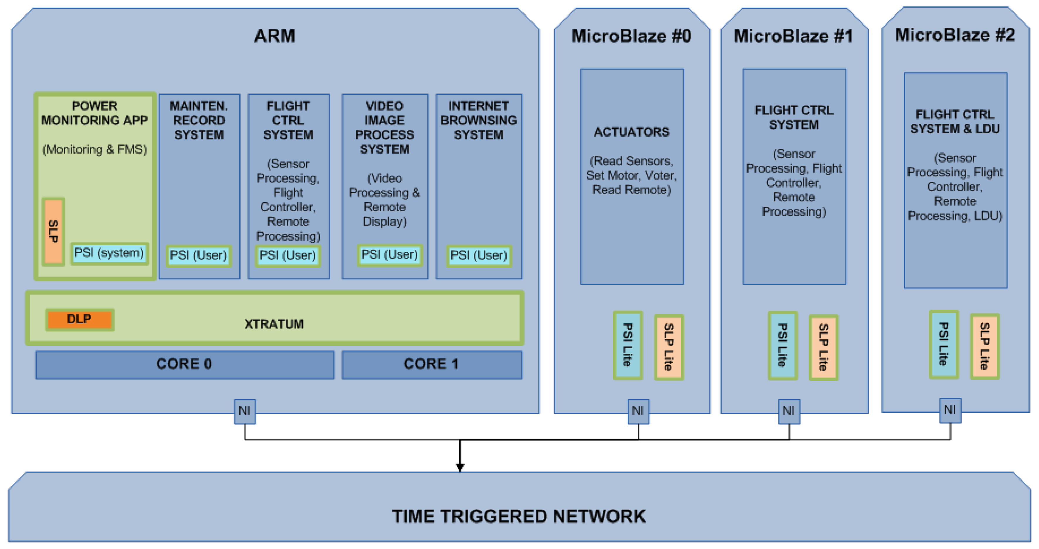
Figure 9, the main software (SW) components of the avionics use case mapped to the SAFEPOWER reference platform are depicted. The systems with the highest DAL are the Flight Control System (FCS) and the Functional Monitoring (FM). The FCS provides all flight logic and laws for the flight and the integration of the requests from the pilot, sensor data and the control surfaces, and the FM embodies the health monitoring of the system. For redundancy, the FCS is tripled. Three other applications have been added for their lower DAL classification. For the evaluation, it is relevant to achieve a spatial and temporal separation of the applications of the SAFEPOWER mixed-criticality avionic system. In addition, it is also important not to compromise the reliability and safety of the software during power-saving operations on the hardware.
The potential benefits of studying the avionics use case are very significant and can be summarized as follows:
Achieving a better understanding of how power-saving techniques can be applied to a mixed criticality systems with safety-critical functions distributed over several nodes/tiles without compromising the functional integrity.
Executing safety-, mission- and non-critical applications on the same multicore platform with low-power services would result in increased payload fraction.
5.2.2. Mapping Avionic UC to the SAFEPOWER Reference Architecture
Presented in the following is a brief description of each of the applications in this avionic use case and their mapping to the SAFEPOWER platform (visualized in
Figure 9).
Flight Control System (FCS): The FCS was implemented on three cores for triple modular redundancy (TMR). It is found on the first ARM core, together with Functional Monitoring System (FMS) and Maintenance Recording System (MRS) applications, and on two MicroBlazes. This is the most critical application and is responsible for the flight. In order to have a stable flight, it is scheduled to run with a frequency of 500 Hz.
Functional Monitoring System (FMS): A use case-specific functional monitor application was implemented in the health monitoring partition on the ARM core. Every time a partition or MicroBlaze function is executed, it sends an updated report to the monitor. The monitor compares the report from the previous one and can then detect if the functions are not executing at the specified rate. Furthermore, for partitions on the ARM, the monitor is able to utilize health monitor functionalities in order to get the partition slack time.
Maintenance Recording System (MRS): The MRS was implemented on the first ARM core together with FCS and FMS applications. Its task is to record FMS data.
Video Imaging Processing System (VIPS): The VIPS was implemented on the second ARM core together with the Internet Browsing System (IBS) application. This application reads a picture from the memory (DDR), converts the picture from color to black and white and sends it back to the memory. It is a very memory intense application and sends 46.7 Mbyte/s (800 × 600, 24 bit at 34 fps).
Internet Browsing System (IBS) The IBS was implemented on the second ARM core together with the VIPS application. This application is exercised on the dummy source (reading and processing). In a real aircraft, it is used by the pilot to read manuals and such. This application is subjected to reduced schedule, i.e., turning off the partition.
Large Data Update (LDU) system The LDU was implemented on a MicroBlaze together with one instance of the FCS application. This application is exercised on a dummy source (reading and processing), simulating the upload of maps.
5.2.3. Evaluation Setup
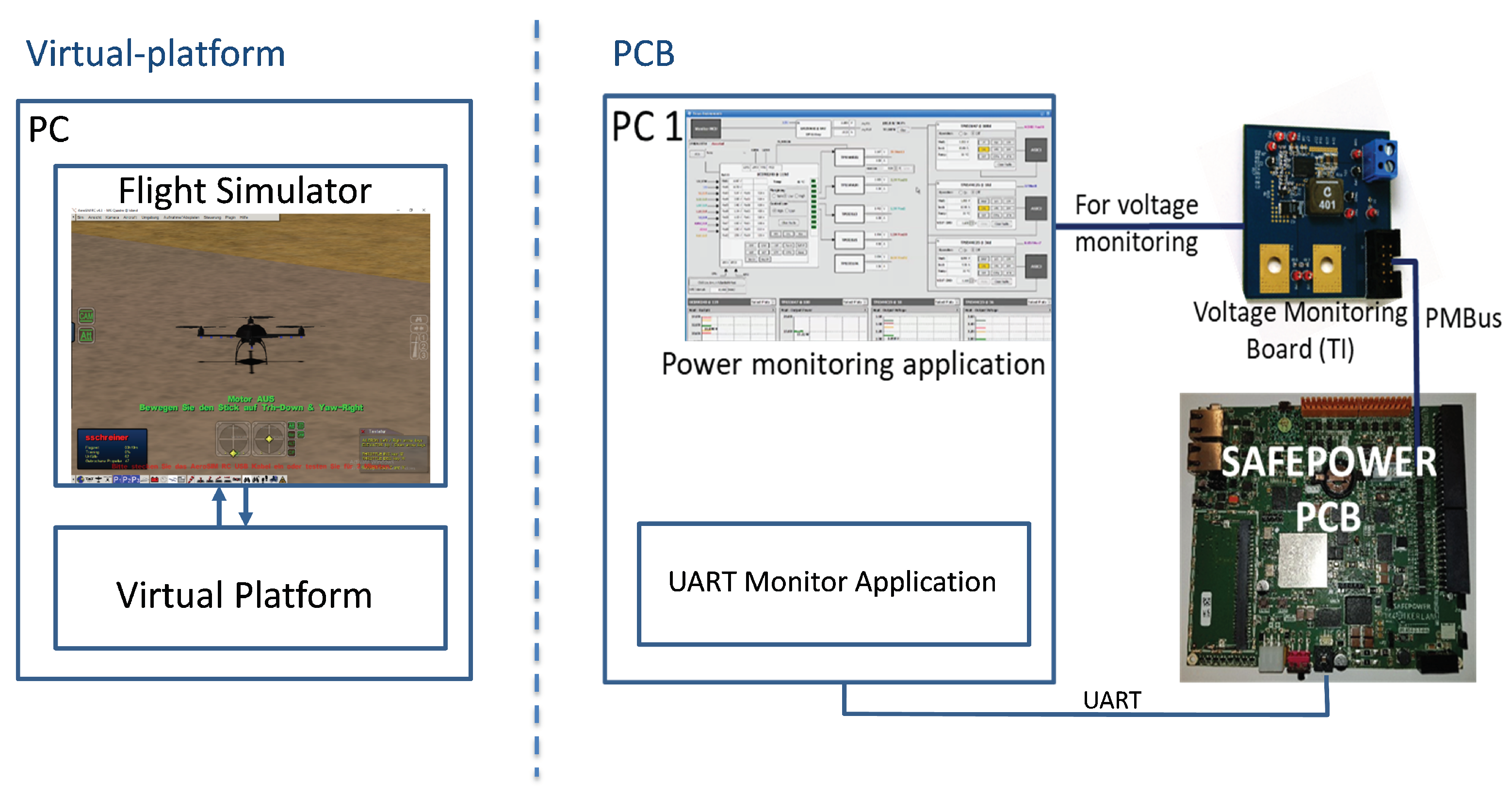
The evaluation is made on the SAFEPOWER OVP and on the SAFEPOWER PCB (see
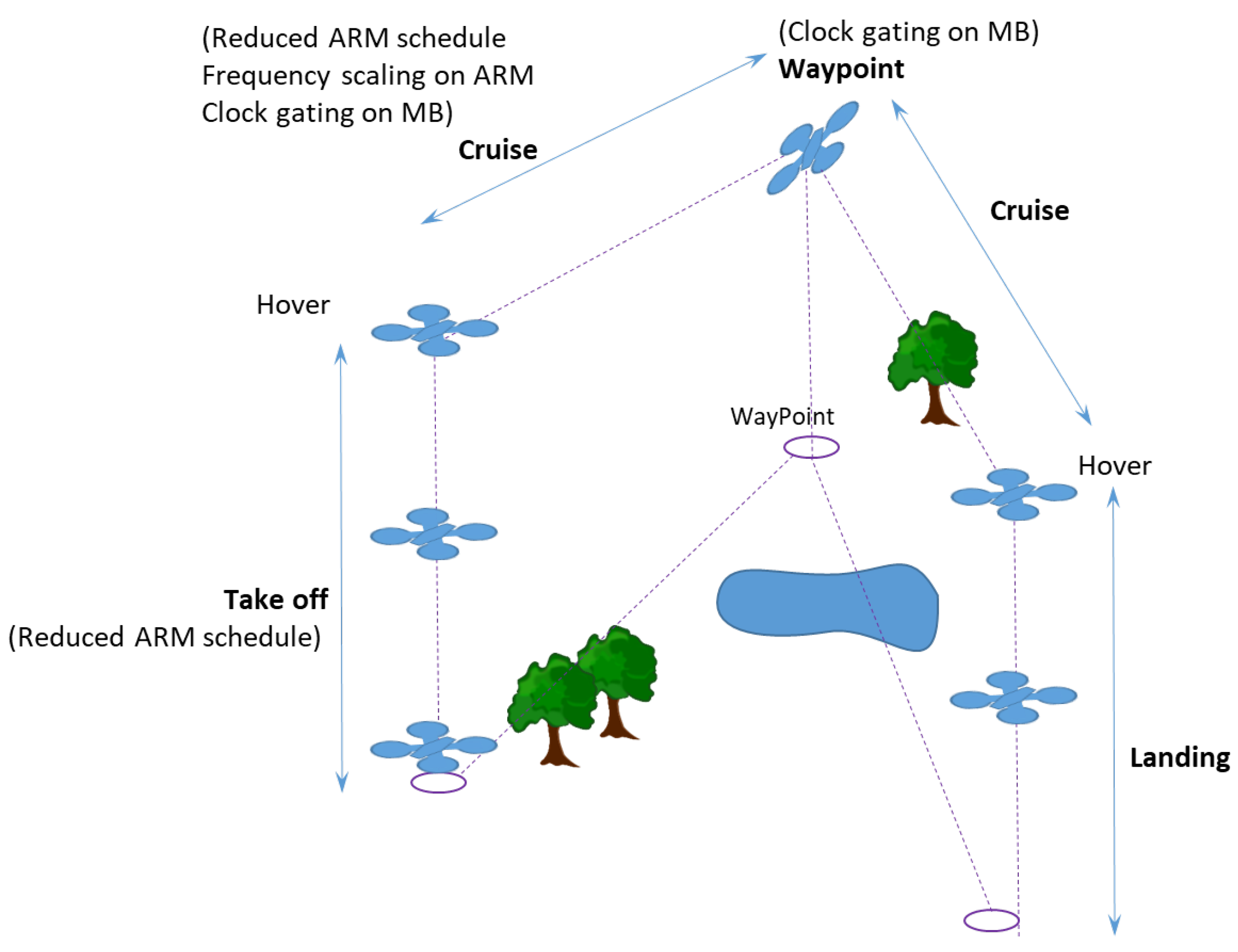
Figure 10) reflecting the different phases of the flight scenario (depicted in
Figure 11).
Table 4 shows the low-power techniques applied in the avionics use case where in each phase, a specific set of low-power techniques was applied, as seen in
Figure 11.
The main steps followed in the evaluation approach are:
Demonstrate correct functionality with and without LPT on the virtual platform with the help of a virtual platform-in-the-loop simulation (see
Figure 10, left), connecting the SAFEPOWER OVP with a flight Simulator (AeroSimRC) and validating the functionality and the correct application of the low-power techniques,
Demonstrate correct functionality on the SAFEPOWER PCB platform without LPT (baseline setup),
Demonstrate correct functionality on the SAFEPOWER platform with LPT usage within each flight scenario,
Record timing parameters, voltage and power values (see
Figure 10 for measurement setup) on the SAFEPOWER PCB platform while executing the above scenarios. Power can be measured separately for every rail of the SAFEPOWER hardware. For that, we have used the TI Fusion Power controller to read out the power values from the on-chip power regulator and logged them to a CSV file.
5.2.4. Avionic UC Evaluation Results
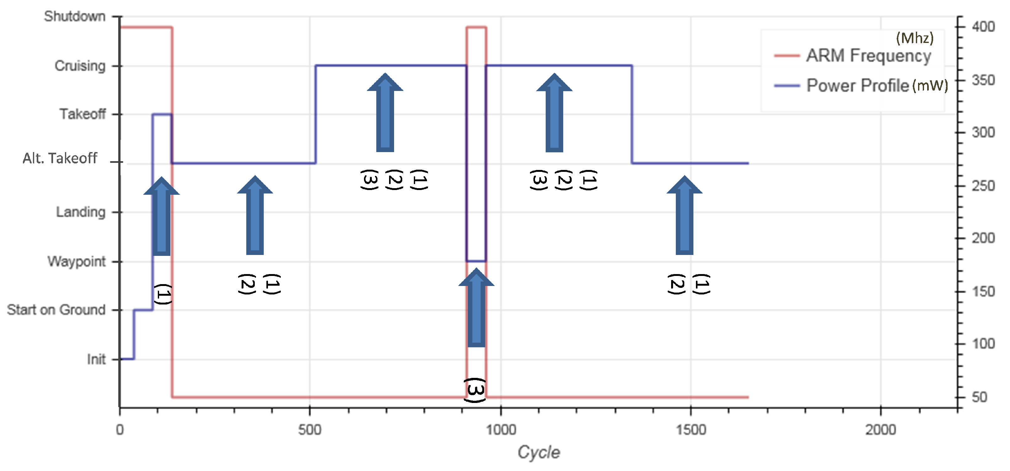
With the help of the VPIL simulation, a flight scenario was simulated to check the functional behaviour of the flight controller.
Figure 12 shows the result of the functional test of the flight scenario, which confirmed the expected behaviour. In addition, the combination of different LPT in each flight phase was verified successfully, as seen in
Figure 12.
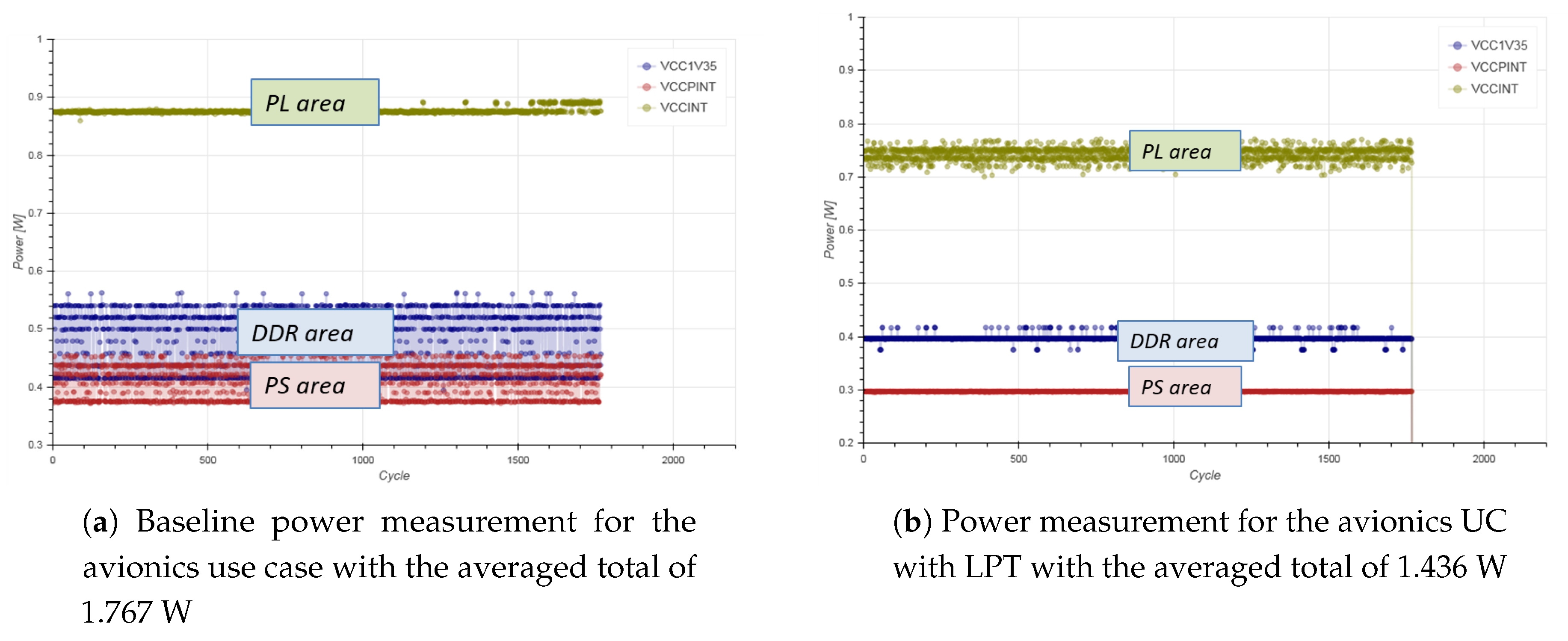
Figure 13 depicts the measured power values for the whole flight scenario once with (see
Figure 13b) and once without the usage of low-power techniques (see
Figure 13a).
The measurement results show that significant power savings were achieved (up to 18.7%) while operating in the pre-defined static schedules of reduced performance within the avionics use case. Obviously, the avionic use case within the SAFEPOWER project limits the usage of possible low-power techniques that can be applied, as the deadlines for the flight critical functionality have to be maintained at all times.
6. Conclusions and Future Work
As a result of the implementation of the SAFEPOWER architecture, it can be concluded that the architecture defined is deployable in any multicore processor without disrupting normal behaviour. Both monitoring and power management services depend on the platform and hardware used, but the architecture could be applied even for power services that have not been taken into account in this work.
The SAFEPOWER architecture implementation in real use cases showed its cross-domain capabilities and that the integration of mixed-criticality applications in a power-efficient way can be easily done. The robustness should be also tested in future work, but a certification authority has positively assessed the safety concept of the railway use case where the proposed architecture was used [
2].
Concerning the experimental results, with the help of avionic and railway use cases, we have demonstrated the viability of the SAFEPOWER reference platform to achieve power savings up to 37% while still guaranteeing time-triggered task execution and time-triggered NoC-based communication. Moreover, the HIL and VPIL setup verification and validation techniques were enabled a complete functional verification flow of the use cases’ implementation, the correct usage of low-power techniques and the correct temporal behaviour, from the virtual platform level to the hardware implementation level.
Author Contributions
Conceptualization, K.G., R.O., M.A.-A., P.O., M.F., J.Ö. and P.B.; software/hardware, M.F., S.S., R.S., T.P., T.S., S.P.F.; validation, M.F., S.S., R.S., D.G., T.P., T.S., S.P.F., T.M., A.M., A.L., Y.B., N.G.R., E.Q.G., J.Ö. and P.O.; investigation, M.F. and P.O.; writing—original draft preparation, M.F., K.G., P.B., R.O., D.G., T.M., N.G.R., E.Q.G., M.A.-A. and P.O.; writing—review and editing, M.F., M.A.-A.; visualization, M.F., P.B., D.G. and P.O.; supervision, M.F.
Funding
This article has been supported by the SAFEPOWER project with funding from the European Union’s Horizon 2020 research and innovation programme under Grant Agreement No. 646531.
Acknowledgments
The authors of this paper would like to thank the entire SAFEPOWER team members for their contributions: Ainara Bilbao, Alfons Crespo, Asier Larrucea, Atai García, Babak Sorkhpour, Blanca Rodriguez, Gustav Johansson, Hamidreza Ahmadian, Ingemar Soderquist, Ingo Sander, Irune Yarza, Jesus Miguel Ruano, Jose Luis Montero, Juan Carlos Diaz, Juan Martin Perez, Kathrin Rosvall, Larry Lapides, Laura Ezcurra, Leire Indurain, Leire Rubio, Manuel Muñoz, María Cristina Zubia, María José Valero, Ola Svärm, Paco Gómez-Molinero, Simon Davidmann, Thomas Granlund, and Torbjörn Månefjord.
Conflicts of Interest
The authors declare no conflict of interest.
References
- Burns, A.; Davis, R.I. Mixed Criticality Systems—A Review. 2015. Available online: https://www-users.cs.york.ac.uk/burns/review.pdf (accessed on 11 March 2019).
- Bilbao, A.; Yarza, I.; Montero, J.; Azkarate-Askasua, M.; Gonzalez, N. A railway safety and security concept for low-power mixed-criticality systems. In Proceedings of the 2017 IEEE 15th International Conference on Industrial Informatics (INDIN), Emden, Germany, 24–26 July 2017; pp. 59–64. [Google Scholar] [CrossRef]
- Obermaisser, R.; Weber, D. Architectures for mixed-criticality systems based on networked multi-core chips. In Proceedings of the IEEE Conference on Emerging Technology and Factory Automation (ETFA), Berlin, Germany, 6–9 September 2014. [Google Scholar]
- Ficek, C.; Feiertag, N.; Richter, D.K. Apply AUTOSAR Timing Protection to Build Safe and Efficient ISO 26262 Mixed-Criticality Systems. 2013. Available online: http://web1.see.asso.fr/erts2012/Site/0P2RUC89/4C-4.pdf (accessed on 11 March 2019).
- Crespo, A.; Masmano, M.; Coronel, J.; Peiró, S.; Balbastre, P.; Simó, J. Multicore partitioned systems based on hypervisor. IFAC Proc. Vol. 2014, 47, 12293–12298. [Google Scholar] [CrossRef]
- Ahmadian, H.; Obermaisser, R.; Abuteir, M. Time-Triggered and Rate-Constrained On-chip Communication in Mixed-Criticality Systems. In Proceedings of the 2016 IEEE 10th International Symposium on Embedded Multicore/Many-core Systems-on-Chip (MCSOC), Lyon, France, 21–23 September 2016; pp. 117–124. [Google Scholar] [CrossRef]
- Grüttner, K. Empowering Mixed-Criticality System Engineers in the Dark Silicon Era: Towards Power and Temperature Analysis of Heterogeneous MPSoCs at System Level. In Model-Implementation Fidelity in Cyber Physical System Design; Molnos, A., Fabre, C., Eds.; Springer: Cham, Switzerland, 2017; pp. 57–90. [Google Scholar] [CrossRef]
- Völp, M.; Hähnel, M.; Lackorzynski, A. Has energy surpassed timeliness? Scheduling energy-constrained mixed-criticality systems. In Proceedings of the 2014 IEEE 19th Real-Time and Embedded Technology and Applications Symposium (RTAS), Berlin, Germany, 15–17 April 2014; pp. 275–284. [Google Scholar] [CrossRef]
- Nelson, A.; Molnos, A.; Goossens, K. Composable power management with energy and power budgets per application. In Proceedings of the 2011 International Conference on Embedded Computer Systems: Architectures, Modeling and Simulation, Samos, Greece, 18–21 July 2011; pp. 396–403. [Google Scholar] [CrossRef]
- Fakih, M.; Lenz, A.; Azkarate-Askasua, M.; Coronel, J.; Crespo, A.; Davidmann, S.; Diaz Garcia, J.C.; Romero, N.G.; Grüttner, K.; Schreiner, S.; et al. SAFEPOWER project: Architecture for safe and power-efficient mixed-criticality systems. Microprocess. Microsyst. 2017, 52, 89–105. [Google Scholar] [CrossRef]
- Schreiner, S.; Seyyedi, R.; Fakih, M.; Grüttner, K.; Nebel, W. Towards Power Management Verification of Time-triggered Systems Using Virtual Platforms. In Proceedings of the 18th International Conference on Embedded Computer Systems: Architectures, Modeling, and Simulation, SAMOS ’18, Pythagorion, Greece, 15–19 July 2018; ACM: New York, NY, USA, 2018; pp. 81–88. [Google Scholar] [CrossRef]
- Seyyedi, R.; Schreiner, S.; Fakih, M.; Grüttner, K.; Nebel, W. Functional Test Environment for Time-Triggered Control Systems in Complex MPSoCs using GALI. In Proceedings of the 2018 21st Euromicro Conference on Digital System Design (DSD), Prague, Czech Republic, 29–31 August 2018; pp. 711–718. [Google Scholar]
- Onaindia, P.; Poggi, T.; Azkarate-askatsua, M.; Grüttner, K.; Fakih, M.; Peiro, S.; Balbastre, P. A Hypervisor Architecture for Low-Power Real-Time Embedded Systems. In Proceedings of the Euromicro Conference on Digital System Design (DSD), Prague, Czech Republic, 29–31 August 2018. [Google Scholar]
- Orgerie, A.C.; de Assuncao, M.D.; Lefevre, L. A Survey on Techniques for Improving the Energy Efficiency of Large-scale Distributed Systems. ACM Comput. Surv. 2014, 46, 1–31. [Google Scholar] [CrossRef]
- Stangaciu, C.S.; Micea, M.V.; Cretu, V.I. Energy efficiency in real-time systems: A brief overview. In Proceedings of the 2013 IEEE 8th International Symposium on Applied Computational Intelligence and Informatics (SACI), Timisoara, Romania, 23–25 May 2013; pp. 275–280. [Google Scholar]
- Chen, P.; Shie, M.C.; Zheng, Z.Y.; Zheng, Z.F.; Chu, C.Y. A Fully Digital Time-Domain Smart Temperature Sensor Realized With 140 FPGA Logic Elements. IEEE Trans. Circuits Syst. I Regul. Pap. 2007, 54, 2661–2668. [Google Scholar] [CrossRef]
- Lefebvre, C.; Montero, J.L.; Rubio, L. Implementation of a fast relative digital temperature sensor to achieve thermal protection in Zynq SoC technology. Microelectron. Reliabil. 2017, 79, 433–439. [Google Scholar] [CrossRef]
- Bagatin, M.e.A. Temperature dependence of neutron-induced soft errors in SRAMs. Microelectron. Reliabil. 2012, 52, 289–293. [Google Scholar] [CrossRef]
- Fakih, M.; Poggi, T.; Peiro, S.; Lenz, A.; Mohammadat, T. Final Low Power Techniques. Technical Report D2.3, SAFEPOWER Project. 2018. Available online: http://safepower-project.eu/ (accessed on 11 March 2019).
Figure 1.
SAFEPOWER architecture for low-power safety-relevant systems. SLP, Static Low-Power; PSI, Power Services Interface.
Figure 1.
SAFEPOWER architecture for low-power safety-relevant systems. SLP, Static Low-Power; PSI, Power Services Interface.
Figure 2.
Scheduling example with 5 partitions, 2 operational (Op) modes and 2 profiles [
13]. In Op Mode 1, only Partition 1 and Partition 3 are active and have two profiles each with a static schedule plan: the original Profile 0 where no Low-Power Techniques (LPT) were applied and the low-power profile where the frequency was decreased such that the finishing of partitions remained within the static estimated worst-case execution times (WCETs). In Op Mode 2, except Partition 1, all other partitions were active for which also static schedules with two profiles (Original Profile 0 with no LPT and Low-Power Profile 1) can also be run during runtime.
Figure 3.
SAFEPOWER virtual hardware platform. OVP, Open Virtual Platforms; PL, Programmable Logic; NI, Network Interface.
Figure 3.
SAFEPOWER virtual hardware platform. OVP, Open Virtual Platforms; PL, Programmable Logic; NI, Network Interface.
Figure 4.
Railway use case.
Figure 4.
Railway use case.
Figure 5.
Mapping railway use case for the SAFEPOWER reference architecture.
Figure 5.
Mapping railway use case for the SAFEPOWER reference architecture.
Figure 6.
XtratuM schedule used for the tests in the dual-core configuration. DIAG, Diagonal.
Figure 6.
XtratuM schedule used for the tests in the dual-core configuration. DIAG, Diagonal.
Figure 7.
Operation modes of railway UC.
Figure 7.
Operation modes of railway UC.
Figure 8.
Evaluation setup of railway UC on the SAFEPOWER virtual platform and PCB. PoIL, Power Interface Library.
Figure 8.
Evaluation setup of railway UC on the SAFEPOWER virtual platform and PCB. PoIL, Power Interface Library.
Figure 9.
Mapping avionic UC to the SAFEPOWER reference architecture.
Figure 9.
Mapping avionic UC to the SAFEPOWER reference architecture.
Figure 10.
Evaluation setup of the avionics UC of SAFEPOWER OVP (left) and the PCB board (right).
Figure 10.
Evaluation setup of the avionics UC of SAFEPOWER OVP (left) and the PCB board (right).
Figure 11.
Avionics use case flight scenarios.
Figure 11.
Avionics use case flight scenarios.
Figure 12.
Evaluating the avionics UC functionality in the SAFEPOWER virtual platform with and without LPT for the flight scenario. (1) stands for reduced ARM schedule, (2) for frequency scaling and (3) for clock gating modes.
Figure 12.
Evaluating the avionics UC functionality in the SAFEPOWER virtual platform with and without LPT for the flight scenario. (1) stands for reduced ARM schedule, (2) for frequency scaling and (3) for clock gating modes.
Figure 13.
Avionics UC power measurement results for the flight scenario at the hardware level with and without the usage of low-power techniques.
Figure 13.
Avionics UC power measurement results for the flight scenario at the hardware level with and without the usage of low-power techniques.
Table 1.
Evaluation goals of the SAFEPOWER reference architecture with the main contributions of this article. UC: Use Case.
Table 1.
Evaluation goals of the SAFEPOWER reference architecture with the main contributions of this article. UC: Use Case.
| Requirement | Covered in This Article | Main Result(s) |
|---|
| Controllability of power and temperature | Partially, in rail-way UC, main concept in [13] | • Hypervisor monitoring partition captures faults and switches to safe mode |
| Observability of timing and power | Partially, in both UCs, concept in [11,12,13] | • Monitoring partition to observe power rails and temperature on the PCB
• Validation of low-power methods and RT schedules on the virtual platform [11,12] |
| Schedulability of hard real-time applications under power management | Yes, main contribution | • Low-power savings up to 37% on hard real-time industrial use cases |
| Certifiability of power and temperature management techniques | No, covered in [2] | • Safety compliant low-power architecture with 3rd party expert assessment |
Table 2.
Overview of low-power techniques and their implications (taken from [
10]). DVFS, Dynamic Voltage and Frequency Scaling.
Table 2.
Overview of low-power techniques and their implications (taken from [
10]). DVFS, Dynamic Voltage and Frequency Scaling.
| Low-Power Technique | Targeted Power Source | Disadvantage(s) |
|---|
| Voltage Scaling | Dynamic and Static | Limited to manufacturing retention voltage. Assignment of values from the “safe” interval. Increasing application execution time. Can cause possible deadline missing
|
| DVFS | Dynamic and Static | Limited to retention voltage/frequency. Assignment of values from the “safe” interval. Finding lowest possible operating frequency and supply voltage is not easy Increasing application execution time. Can cause possible deadline missing
|
| Clock gating | Dynamic | |
| Power gating | Static | |
| Microarchitectural | Static | |
| Optimisations | | |
Table 3.
Evaluation results of railway UC on the SAFEPOWER PCB. For each state, the applied low-power technique, execution time of the critical task, the power saving in % and the temperature differences are shown. Blank spaces indicate that no differences have been found. If a test could not be performed, the corresponding cell is marked with Not Applicable (NA). PS, Processing System.
| | Critical Task
Execution Time | Monitoring
Partition
Execution Time | Power Measurement | Voltage
Measurement | Temperature
Measurement |
|---|
Normal/Normal
(No LPT) | 4.2 ms | 28.3 ms | PS
PL
DDR | 0.389 W
0.606 W
0.642 W | PS 0.994 V
PL 0.995 V
DDR 1.328 V | 55.8 °C |
Normal/Trimmed
(Frequency Scaling) | +46% | +26% | PS
PL
DDR | −15%
0%
−4% | | −0.5 °C |
Normal/Dropped
(Partition off) | | | PS
PL
DDR | −12%
0%
−13% | | −1.1 °C |
Fault/Normal
(Voltage Scaling) | | | PS
PL
DDR | −27%
0%
0% | PS voltage:
−10% | −1.7 °C |
Fault/Trimmed
(DVFS) | +46% | +26% | PS
PL
DDR | −37%
0%
−4% | PS voltage:
−10% | −1.8 °C |
Fault/Dropped
(PL off) | | | PS
PL
DDR | 0%
0%
−85% | PL voltage:
−48% | NA |
Table 4.
Low-power techniques applied in the avionics use case.
Table 4.
Low-power techniques applied in the avionics use case.
| Mode | Description |
|---|
| Fully active | No power-saving operation applied |
| Reduced schedule | Reduced schedule on ARM cores
(turning off partitions) |
| Clock gating | Clock gating on the MicroBlazes |
| Frequency scaling | Frequency scaling on the ARM processors
(a prerequisite is that the reduced schedule is also active) |
© 2019 by the authors. Licensee MDPI, Basel, Switzerland. This article is an open access article distributed under the terms and conditions of the Creative Commons Attribution (CC BY) license (http://creativecommons.org/licenses/by/4.0/).

 ,
, 


