1. Introduction
The tasks of grasping and lifting a box or transporting it from one place to another seem really trivial for an average human. They are things that we can do automatically, without using all our brain capacity. We do not have to think about how or where to apply the necessary forces to avoid a box falling on the floor. However, if we observe a baby playing with colored cubes or opening a Christmas present, it seems as though this task was once a real challenge for us. The baby is learning how to handle the box by exploring it, applying different forces to different surfaces of the box, letting it fall, etc. It takes about two years for a child to achieve a dexterous manipulation capacity [
1].
Technological advances are allowing humans to replace some thankless, repetitive, and sometimes unhealthy activities by automated systems. It is a fact that societies in advanced countries are becoming older due to a declining birth rate and increasing life expectancy. Consequently, it is becoming increasingly important to find substitutes for those professions traditionally occupied by a younger sector, such as waiters [
2], or for those activities that are more physically demanding.
For an elderly person, carrying a heavy box up the stairs or manipulating it could be a laborious task. If that person also has a disability or needs a cane, the difficulty increases. For that reason, with the aim of meeting that need, the humanoid robot TEO packer-unpacker, TEO, is currently being developed in the RoboticsLab of the University Carlos III in Madrid. In this application, the final goal is to achieve the dexterous bi-manipulation of boxes using the arms of a humanoid robot.
In reviewing the current state-of-the-art in bi-manipulation tasks, we find examples of grasping of small objects performed by the fingers of a hand of a robotic arm [
3,
4,
5]. In the end, the task of grasping a box with two arms of the robot is similar to two-point forces applied over a surface by the tips of a hand. Regarding these kinds of manipulation tasks using hands, several studies on the slippage of objects while they are being manipulated have also been conducted using sensors [
6,
7,
8].
The previously cited examples focused on manipulation with the fingers of robotic hands. However, there have also been developments in the manipulation of boxes by robots, several pick-and-place solutions implemented in warehouses [
9,
10,
11], etc. Furthermore, there have also been several studies on dual arm systems for lifting boxes [
12,
13,
14]. These works are centered on lifting boxes or pick-and-place tasks.
Nevertheless, in these movement strategies, the robotic system is always looking at the same faces of the box, making it impossible to find the opening face of the box if it is not on one of these visible sides.
If we compare the actions currently performed to bi-manipulate a box with the process used by humans, we can find several differences. However, to give the robot the capability of performing a dexterous manipulation, the robot should start by identifying the box using vision techniques, obtaining the position of the box in the image and its size, as a person would. Then, this robot should learn how to manipulate it. Given some primitive movements, the robot will try to move the box, correcting the errors made in the movements until it finally achieves the goal of skilfully manipulating the box.
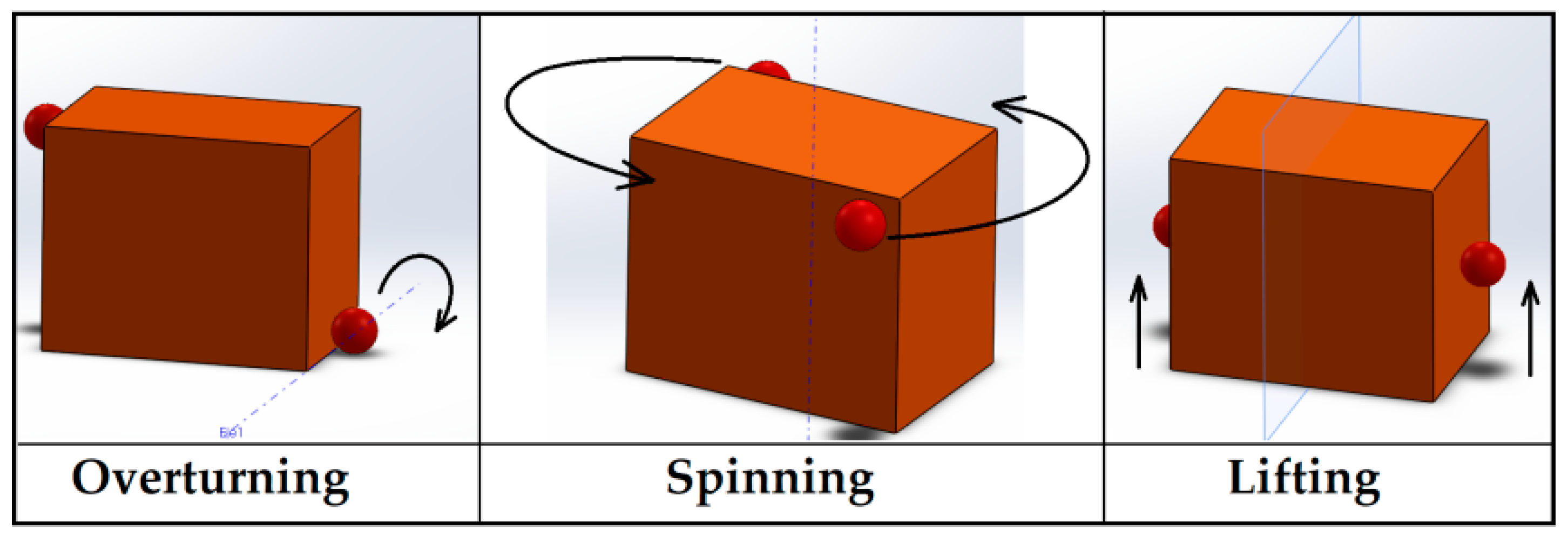
In this paper, a study of three different strategies to bi–manipulate a box without grasping is presented: overturning, lifting, and spinning it on a surface. The dynamics of the movement in each case are studied. The goal is to check the relation between the theoretical physics equations of those movements and the forces detected by the robotic system. Several experiments were performed, which provided data from the sensors (encoders, force sensors, and optical tracking) that are used to develop a manipulation algorithm from those primitive movements.
While reviewing the state-of-the-art in overturning and pushing movements to manipulate a cubic object, several studies [
15,
16,
17] can be found. All of them focused on small objects manipulated by the fingers of a robotic hand. However, when performing this task using two robotic arms to manipulate a larger object (in this case a box), its weight plays an important role, making it important to take into account the dynamics of this object. As there is a lack of studies on such dual-arm tasks, the problem is addressed in this paper. Several studies have been conducted on lifting boxes in dual-arm manipulation tasks [
18,
19]. However, few studies have addressed the problem of lifting the box without knowing the weight. In References [
20,
21], an approach of guessing the weight of the box by combining both force sensors and visual perception of the box is presented. Depending on the movement of the box detected by the vision system, the robot estimates the force needed to lift it up. Another research based on whole-body balance control in lifting an unknown weight has been conducted using HRP-2 [
22]. Through the lifting experiments carried out in this paper, the forces implied in that task are studied. The force pattern, which depends on the success or failure in the lifting action, is obtained with the goal of using this information in the future to train a reinforcement learning system, so that the robot is capable of lifting a box without knowing its weight and only having the feedback from force sensors.
The experiments shown are part of the research on intelligent systems for a humanoid robot capable of bi-manipulating a box and optimizing its movements to find the opening side, as shown in
Figure 1. In this application, the robot is able to identify the features that define the box, as well as its orientation, by computer vision techniques [
23]. Then, the dynamics of the three main movements needed to turn the box in every direction are studied. In this study, knowledge of the movements involved in the task, the reactions caused by the forces applied on the boxes depending on the weight, the size, the friction coefficient of the box against the end effectors, etc., need to be acquired. After the dynamics validation, the primitive movements are checked, and taking into account the workspace of the robot, these primitives will be modified to adapt the movements to boxes of different sizes and weights, which are also positioned in different places of the workspace (research ongoing). Once these movements are adapted to different kinds of boxes, a hybrid control, combining position and force control to manipulate the box, is introduced. Finally, a learning algorithm will be applied to optimize the movements needed to find the opening side of the box.
The remainder of this paper is organized as follows: In Section II, a study of the dynamics involved in the three explained movements related to manipulating boxes is conducted. Section III presents the experiments conducted to validate the dynamics equations. In Section IV, the structure of the hybrid position–force control using the primitive movements is introduced.
2. Study of the Movement Dynamics in Boxes
As seen in [
24], dual arm manipulation tasks can be classified into coordinated (both end effectors should work together by taking into account the feedback from the other in a closed loop) or uncoordinated (open loop). Additionally, while performing coordinated tasks, the movements of the arms can be symmetric or asymmetric.
To manipulate a box by being able to reach all of its sides, the robot needs to be able to make at least three kinds of movements: overturning, spinning, and lifting. These strategies are represented in
Figure 2, where the red points correspond to the position of the end effectors of each arm of the robot.
Taking into account the previous classification, the three movements must be coordinated, because the forces of each end effector have an influence on the other, preventing undesired slippage or displacement of the box. The lifting movement is clearly symmetric with respect to the plane, whereas the overturning is asymmetric, because one of the end effectors will stay fixed to create the rotation movement around the represented axes. In the case of the spinning movement, a symmetric turn around the axis can be considered which goes through the center of the box.
Another classification can also be made: it is clear that the lifting task is kinematically similar to grasping (the robot applies a prehensile manipulation to lift the box up). However, the overturning and spinning movements can be considered as graspless (the forces of each end effector are applied in different directions using a support surface, the table, to generate those movements).
In the following subsections, the dynamics needed to make these movements are explained. Well known physics equations [
25] have been obtained, with two objectives: to verify that those equations and the theoretical results are extrapolatable to our system, the humanoid robot, TEO, and to obtain the data and information needed to create a learning process for the robot that is similar to that of a human being.
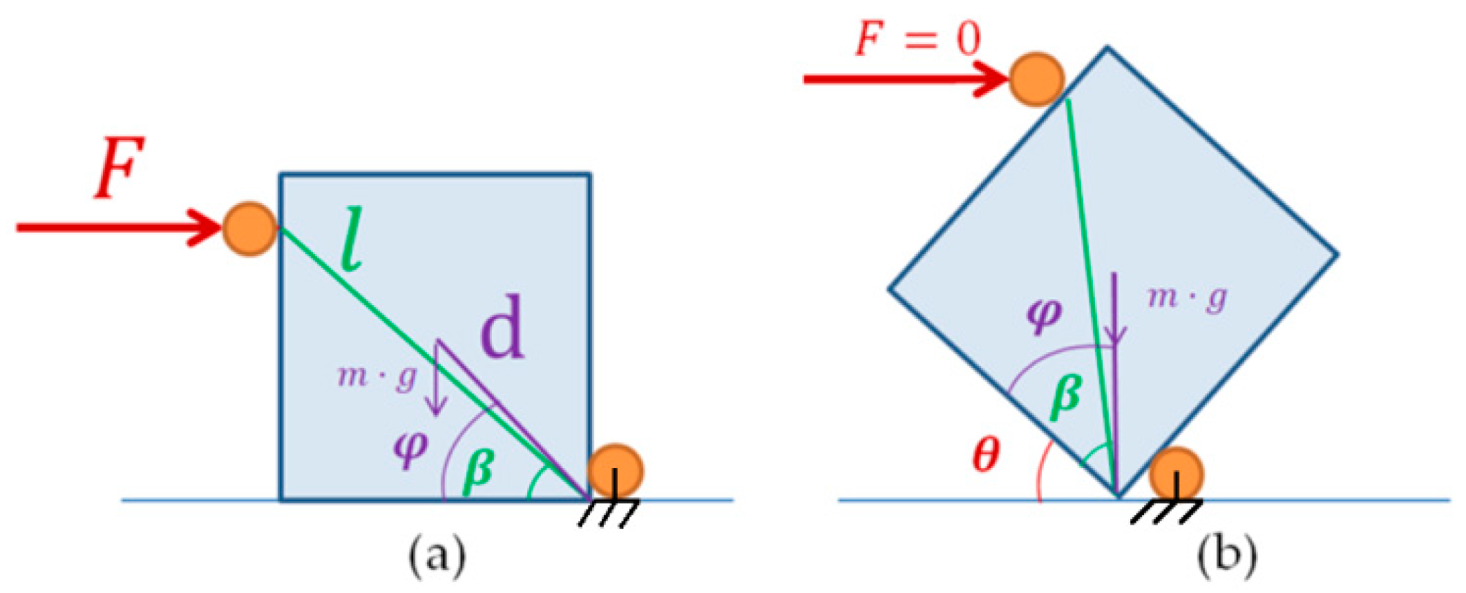
2.1. Overturning Dynamics
As said before, to overturn the box, the robot needs to create a fixed axis where the box will rotate (
Figure 3a). To achieve this, one of the arms will be positioned in the low side, whereas the other will be in the upper side of the box applying the required force to perform the movement. To make a pure overturning movement, the forces are aligned in the same depth plane where the support point has been created by the fixed end effector. For that reason, the problem can be simplified into two dimensions (
Figure 3b).
The minimum force needed to start the overturning movement of the box is defined by Equation (1), where the momentum of the force applied “
” minus the momentum of the weight of the box “
” is equal to the “
I” inertia of the box plus the “
” angular acceleration produced:
As the rotation axis does not correspond to the center of the box, the inertia equation is translated into the vertex, where the rotation, applying Steiner’s Theorem, is produced, as seen in Equation (2):
where “
m” is the mass of the box, “
a” is the length of the base, and “
h” is the height.
Additionally, the horizontal force applied and the force contribution due to the box weight in the horizontal axis are supposed to be applied in the vertex of the box (spinning axis). As stated in Equation (3):
where, as shown in
Figure 4b, “
” is the inclination angle of the box, “
” is the angle between “
l” and the base of the box, and “
” is the angle between the segment created by the center of geometry of the box and the rotation axis in relation to the base.
2.2. Lifting Dynamics
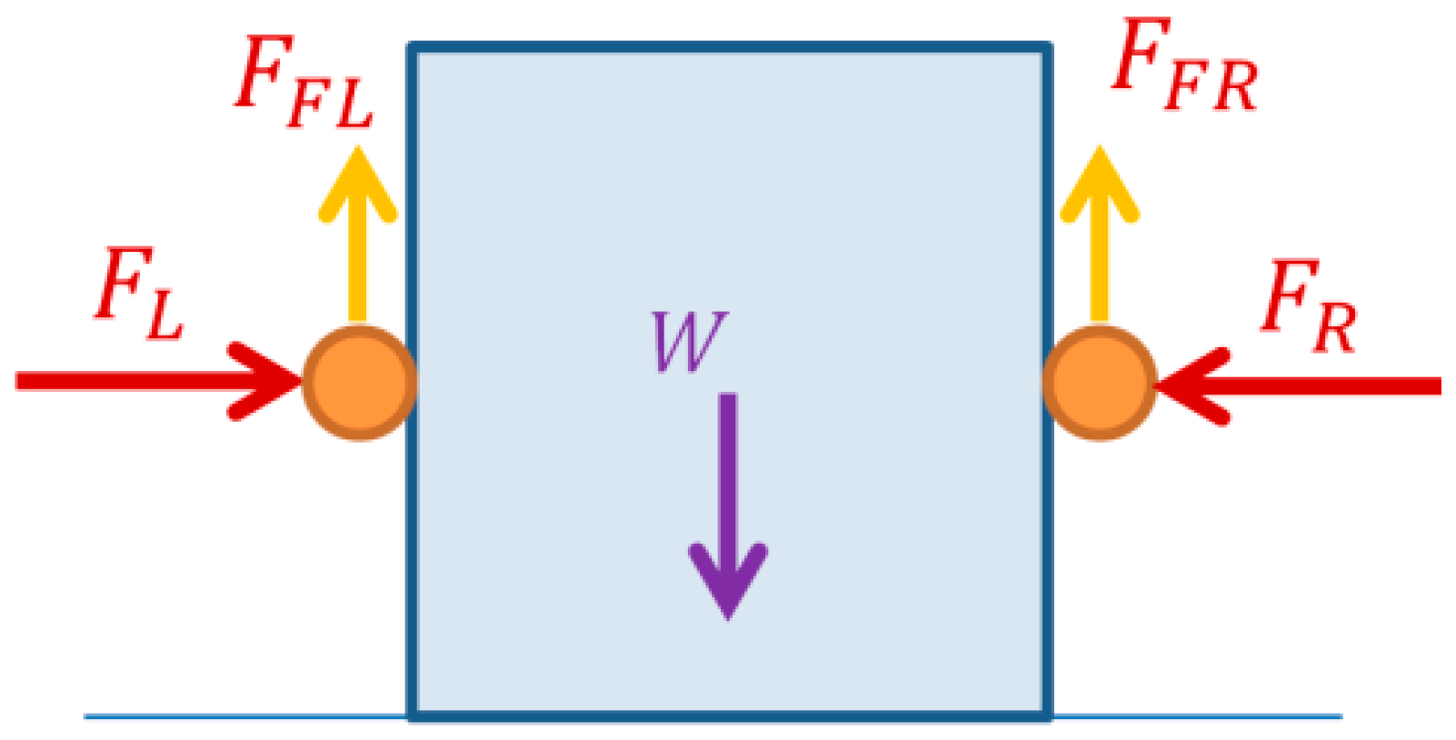
The lifting movement is made by performing a symmetric coordinated trajectory with both arms. In this case, unlike in the previous one, it is really important to maintain the force constant with both hands. In case one of the hands applies a higher force than required, the box could be crushed. However, if the required force is not applied by one of the end effectors of the robot, the result would be that the box would fall on the floor.
The forces for lifting the box must be equal and be applied in opposite directions to avoid any displacement, as seen in
Figure 5. As the lifting movement performed by the robot is made with a low speed, the inertial forces can be depreciated in comparison with the value of the acceleration of the mass caused by the gravity. For that reason, the only force against the movement is the weight of the box “W”, and following the Coulomb friction law [
26], the force applied by each end effector on the surface of the box will be transformed into a static frictional force, in so far as slippage is not desired. Therefore, the sum of the forces made by both arms must be higher than the weight of the box, as seen in Equation (4):
Thus, the left friction force “
” is equal to the right friction force “
”, and the force needed from each hand “
N” is shown in Equation (5):
where “
” is the mass of the box, “
” is the gravity, and “
” is the friction coefficient.
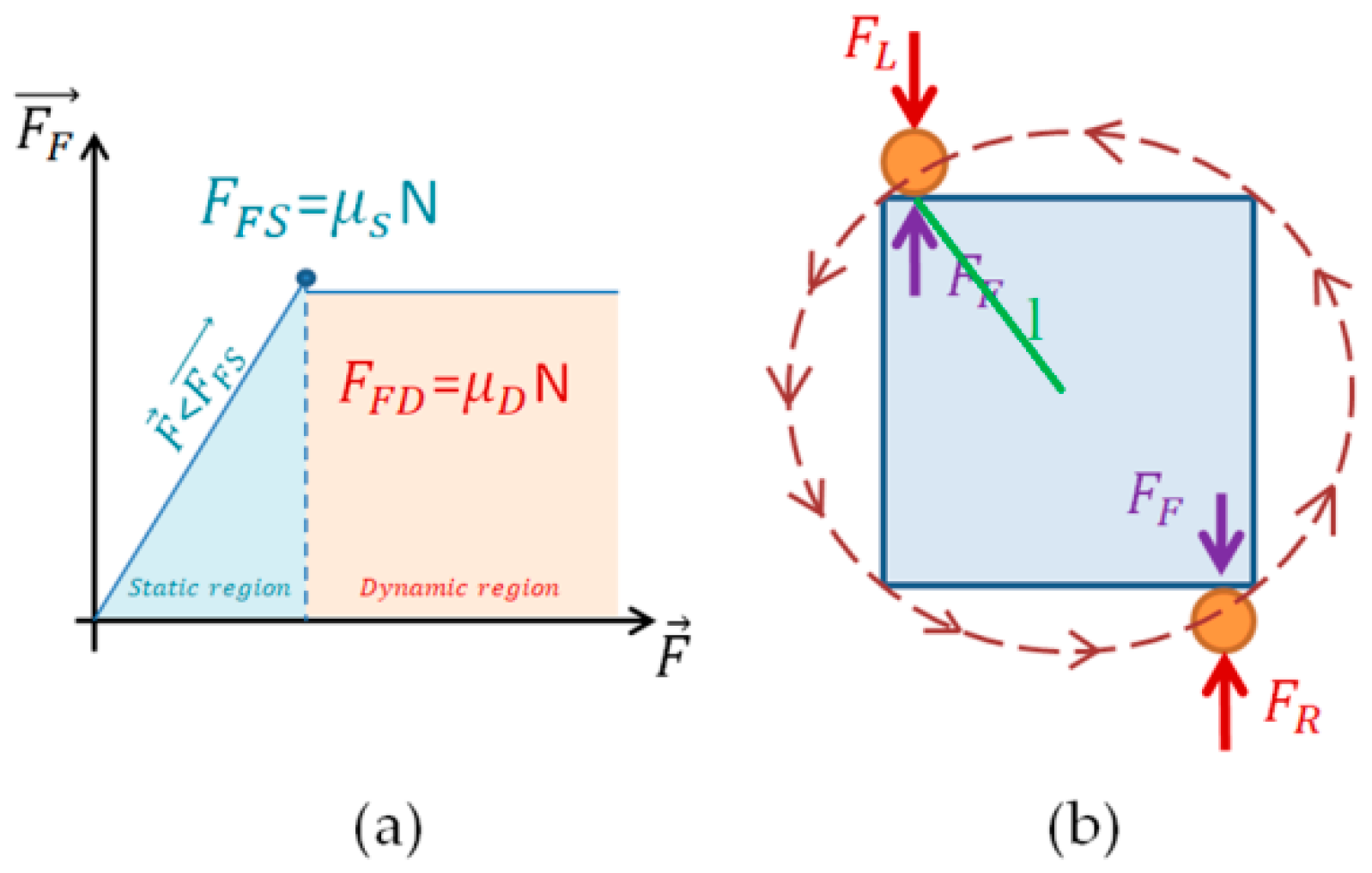
2.3. Spinning Dynamics
Spinning a box over a surface implies a change from a resting state of the object to a movement state where the box will have a slippery movement on the surface where it is placed while spinning. For that reason, two different friction forces need to be considered as shown in
Figure 6a.
The forces needed to make the spinning movement are defined in Equation (6), where the momentum of the sum of the forces applied by both arms “
” minus the friction momentum of the box in relation to the table “
” is equal to the torque “
”:
The forces applied by the right arm “
” and left arm “
” are equal. As both of them have the same value and are applied at the same distance “
l” from the spin axis in the direction that contributes to the motion, both forces will be presented in Equation (7) as “
F”:
where the friction force has been substituted by the “
” friction coefficient, the normal force of the box, and the inertia “I”, according to a squared boxed spinning in the center of geometry, “
a” is the width, and “
b” is the length of the base of the box.
By solving Equation (7), and considering that the spinning movement performed by the humanoid robot is slow, we can approximate the acceleration to a null value, which is the following force equation:
In Equation (8), the force needed in each arm to make the movement is presented. However, the friction coefficient varies. At the beginning, to start the spinning movement, there is a static friction force, as shown in Equation (9). Then, the force applied must be higher than the dynamic friction force, which is slightly lower than the static friction force, as shown in Equation (10).
As mentioned before, in both equations, the forces applied by the right arm “” and the left arm “” are equal, and for that reason, they are simplified into F. The difference between both equations is the static “” and dynamic “” friction coefficients.
3. Experiments to Validate the Dynamics
The equations previously calculated are validated in this section. The goal of these experiments is to confirm that the real response of our system, the humanoid robot, TEO, is consistent with the behavior expected in the theoretical calculus. As a consequence, the primitive movements will be obtained, which will allow us to extrapolate them to different kinds of boxes in the future and apply a hybrid position–force control. A set up of three experiments with the humanoid robot, TEO (one for each kind of box movement), was employed. The information was acquired by implementing a sensor fusion between: the encoders on each of the joints of the arms, to know the real position of the arm during the movement, the force sensors installed on the end effectors to obtain the feedback of the force applied to manipulate the box, and an optical tracking system consisting of eight cameras to check the position of the box with reflectors in the overturning movement.
3.1. Overturning the Box
To check the forces implied in the overturning movement, the problem has been simplified in the experimental set up. To perform this movement, one hand is fixed to create a mechanical earth where the rotation axis is. As a consequence, this movement can be considered as a simple pushing movement. Thus, with the goal of performing the experiment more quickly to verify the forces in the hand, the force has been applied in the frontal axis of the robot. This approach was used in keeping with the concept presented in
Figure 4.
The overturning movement was made using a 0.4m × 0.3m × 0.25m box. Inside, a structure was installed to maintain the mass in the center of the box, shown in Figure 9, despite using different weights (2, 3 and 4 Kg).
The force has been applied at ¾ of the height, so the contact point of the end effector is above the center of mass of the box. This position has been chosen in consideration of Equation (3). The higher and further from the fixed overturning axis the force point is, the lower the force required to perform the movement, as far as “l” is the distance from the point of application of the force to the turning axis and “β” is the angle between “l” and the horizontal increase.
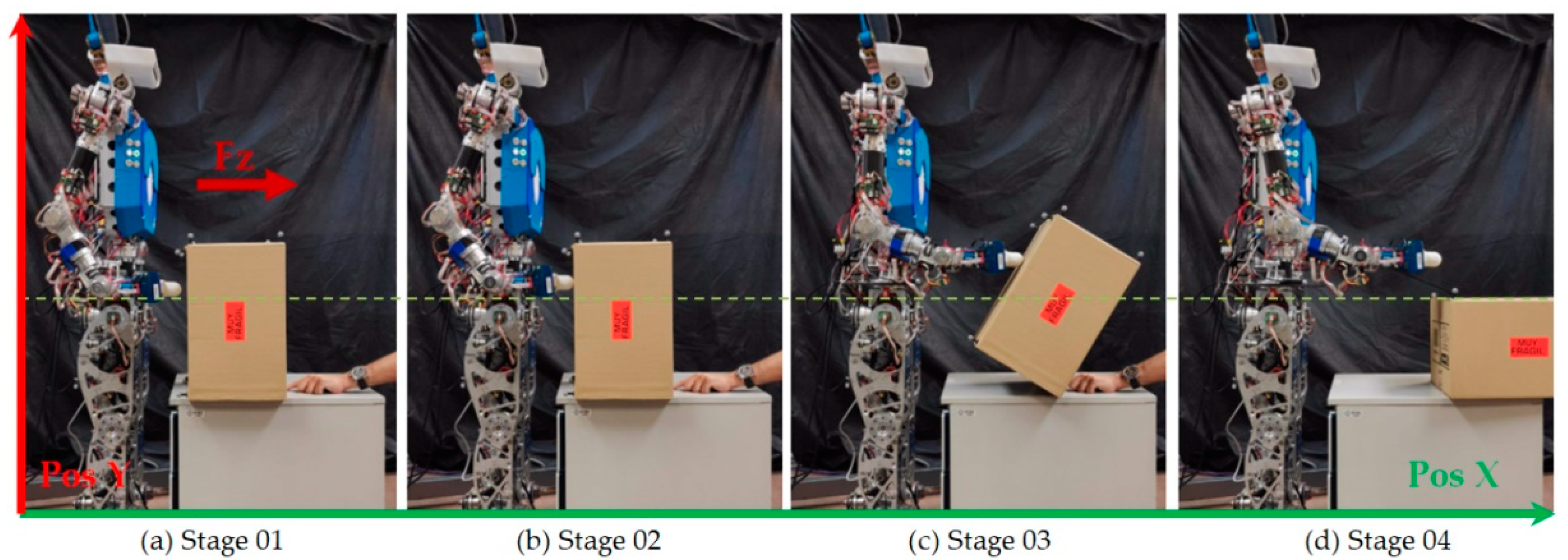
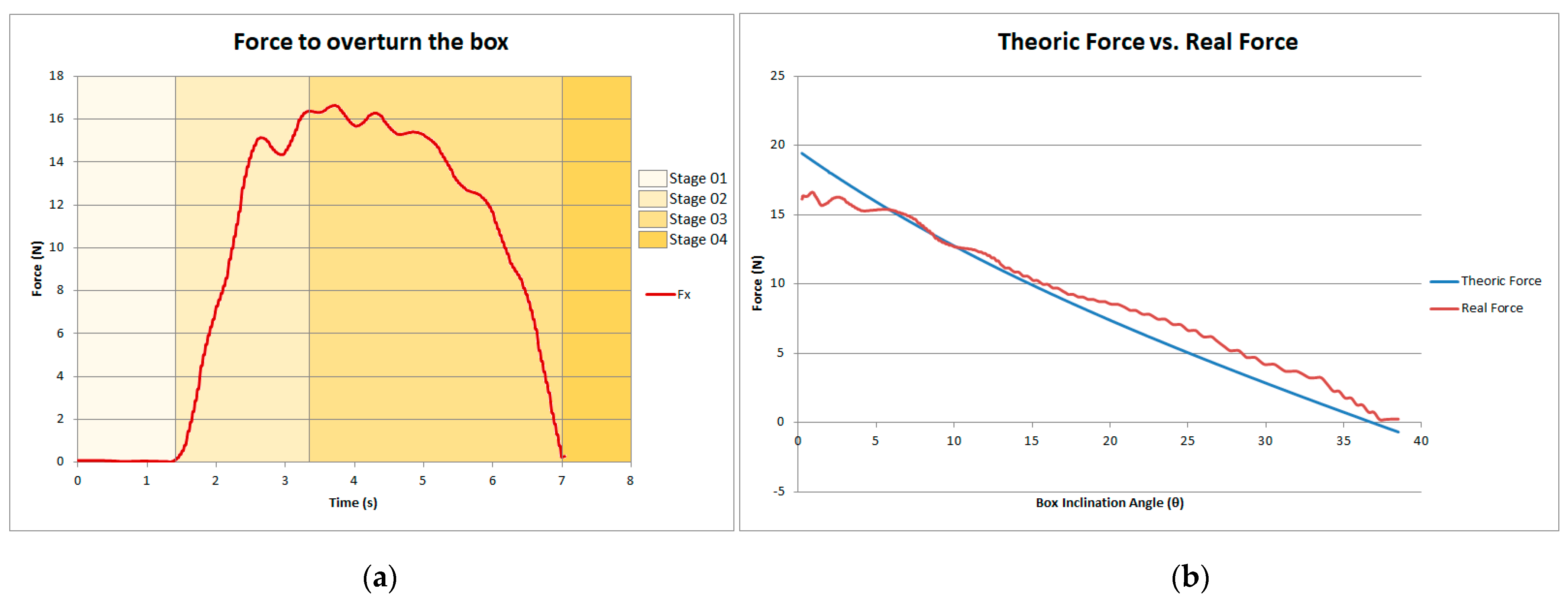
As shown in
Figure 7, the overturning movement can be separated into four different stages: The first one includes the moment in which the arm is getting closer to the box, and there is still no contact. For that reason, at this point, the contact force is equal to zero. In stage 02, the hand has made contact with the surface of the box and starts applying the required force to start the overturning movement of the box. Once the base of the box starts lifting, the needed force to start the movement has been reached. Then, stage 03 begins. The box is being turned, and as a consequence, the mass of the box is surpassing the axis of rotation. For that reason, the force decreases until it reaches a null value. The same amount of mass of the box is in both sides of the rotation axis. The box is in an equilibrium position. From this point, the box starts falling to the other side due to the inertia of its weight. In this step, the robot does not have to apply any force to create the movement. As a consequence, in stage 04, the resultant forces in the end effector are equal to zero. This behavior has also been checked using the data obtained with the force sensor of the hand, as shown in
Figure 8a.
In Equation (3), the relation between the forces needed to overturn the box, depending on the inclination angle, is shown. In
Figure 8b, both the theoretical force calculated with the equation and the real forces detected with the sensor are compared. This representation matches with the movement made in stage 03. As can be seen, the real force is really similar to the theoretical force, so it can be affirmed that the force calculus matches with the real experience.
3.2. Lifting the Box
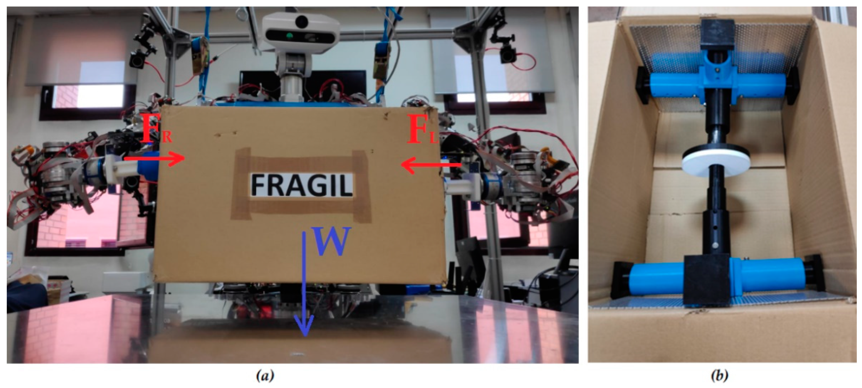
While lifting the box, as shown in
Figure 9a, the friction coefficient between the end effectors and the box plays an important role in determining the force to be applied to avoid it falling, as shown in Equation (5). To carry out the lifting experiments, the box has been positioned in front of the robot. It has been grasped again at ¾ of the height to allow it to be above the center of gravity and thus to prevent any torsion of the box while lifting it. Both arms have applied the force in the middle plane of the box depth in opposite directions. Inside the box, the structure shown in
Figure 9b has been retained to minimize the deformations caused by the forces applied in the grasping.
When humans lift a box, they do not know the exact friction coefficient of their hands regarding the object that they are grasping, nor the value of the weight of that object. However, as a result of knowledge gained from experience, we know whether a surface is going to be more or less slippery. Additionally, seeing the object, the weight can be estimated, and as a consequence, the force is adapted to avoid the object falling. This automated answer is the result of learning based on experience (and many broken objects when we were children). In the experiments involving the lifting of the box, these learning methods are imitated.
3.2.1. Lifting with Different Friction Coefficients
In the first lifting experiment, the friction coefficient has been changed, and the box has been lifted repeatedly in order to find the friction value that avoids the box falling. The box has been considered as a semi-rigid object by setting a rigid structure inside,
Figure 9b. The weight of this structure plus the box is 1.35 Kg, which has been maintained during the experiment so that there is only one variable: the friction.
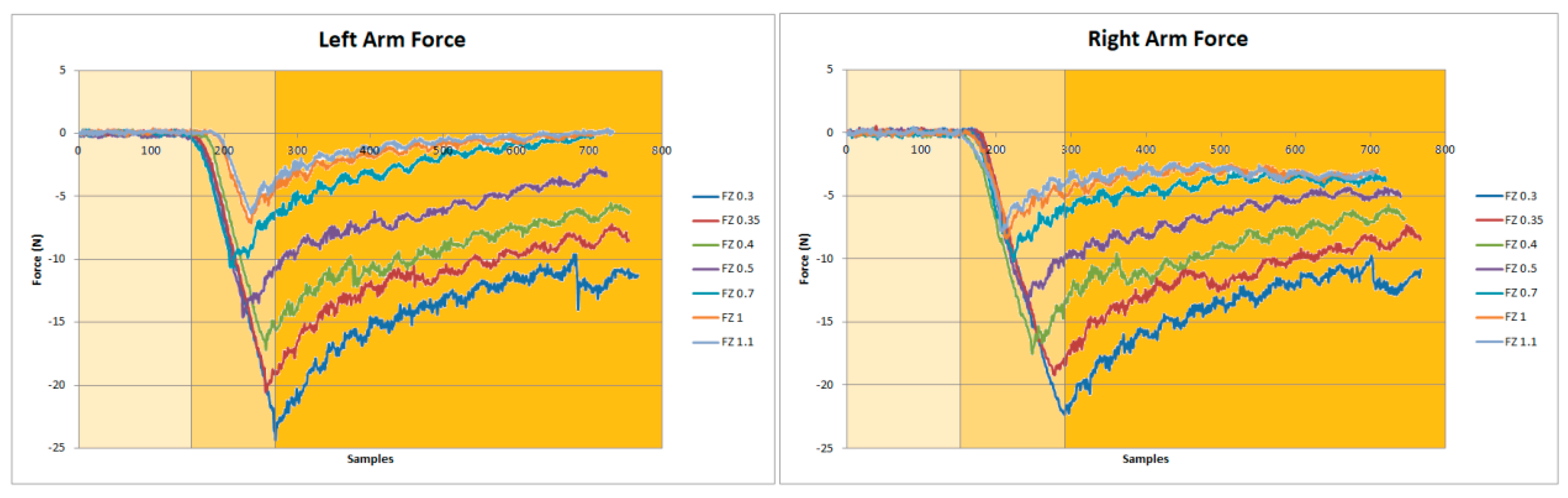
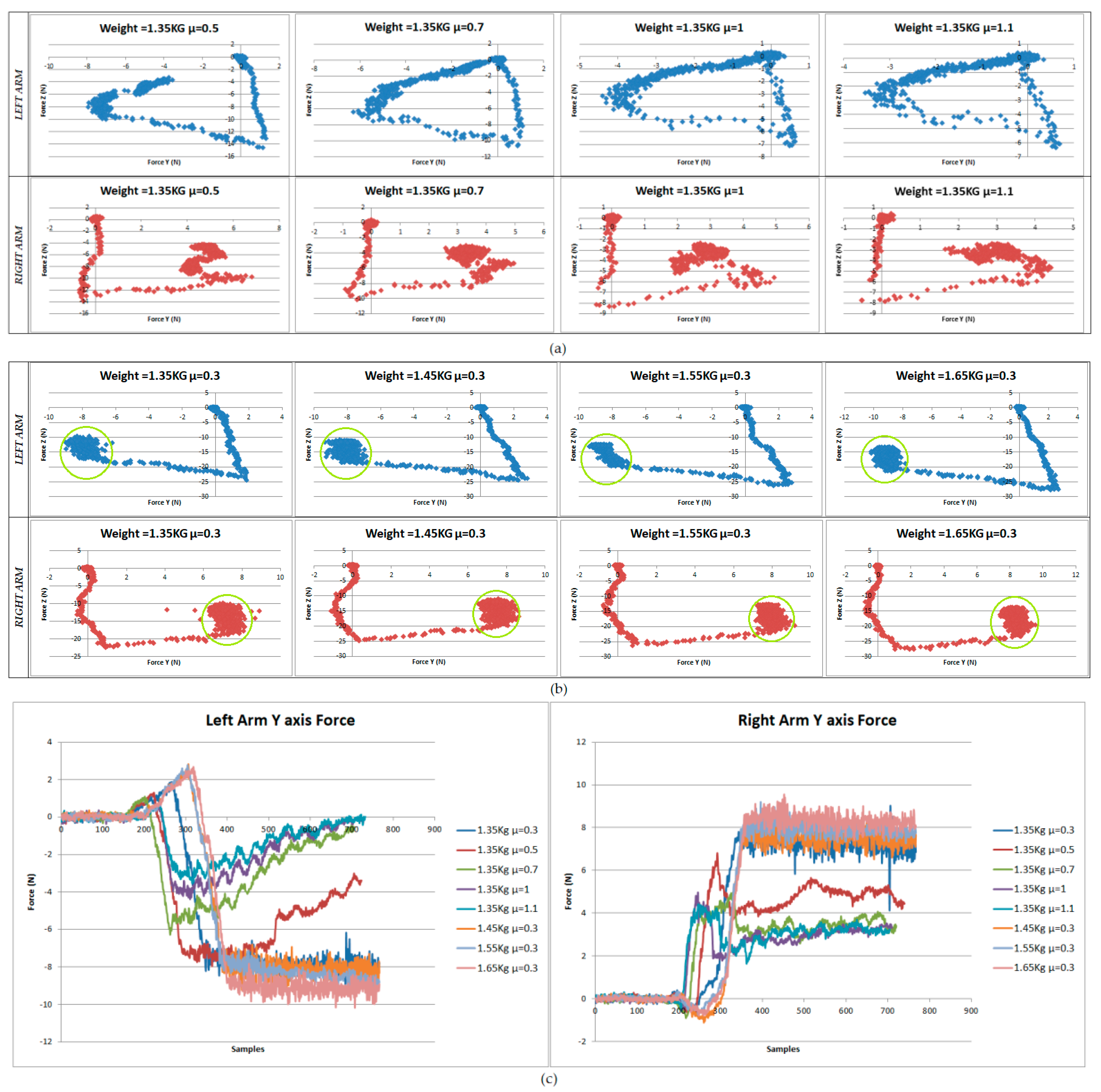
As a result, in
Figure 10, we can see the forces applied by each arm depending on the friction coefficient (mu) used. After trying in a range from 1.1 to 0.3, it was found that the friction coefficient that provides a better grip without slippage and without applying more force than needed is mu = 0.3.
As shown in
Figure 10, the force applied can also be divided into three stages. The first stage is the approximation of the end effectors to the box. The second stage starts when the end effectors are in contact with the box surface. Finally, in third stage, the lifting process is recorded. At this stage, the force decreases as the box is lifted. This is because the box is a semi-rigid solid, so there is some deformation, and no force control was used. During all repetitions of the lift, the box fell when the value of the force was less than 10N.
3.2.2. Lifting with Different Weights and a 0.3 Friction Coefficient
After choosing the value of 0.3 for the friction coefficient, a new experiment involving the changing of the box weights was conducted in order to determinate whether, at this value, the box was slippery. As seen in
Figure 11, the following weights used were: 1.35 Kg, 1.45 Kg, 1.55 Kg and 1.65 Kg. As the weight increases, the force needed to grasp the box with each arm also increases. The box was lifted in the four cases, thus validating the friction coefficient that was previously set up.
These experiments were conducted simplifying the problem, by giving the robot the information about the weight and the friction coefficient of its end effectors regarding the box. However, as mentioned before, while we, as humans, lift boxes, we do not need to know their exact weight or, the friction coefficient, nor do we need to see them to obtain the visual feedback required to know that we are lifting them. We try to lift it, and then, due to the response of our hands to the material of the box or the weight and if it slips or not, we decide to apply a force that allows the desired movement. Thus, coming back to a robotic system, should we expect some signal in the force sensors that allows the robot to know if the box has been lifted without having any other feedback? Could the robot lift the box without knowing the material of the box, or its weight?
3.2.3. Force Patterns during the Successful Lifting of the Box
To check if there is any useful information from the force sensors, the data acquired in the successful lifting experiments and the data from the failed ones were compared.
Considering the results for the relation between the force in the Z axis (normal force against the box surface) and the force in the Y axis (force caused by the weight of the box), shown in the graph, there is a difference in the results obtained when the box was not lifted (
Figure 12a) and when the box was lifted (
Figure 12b). In the case when the box was lifted, a small dispersion can be observed in the samples obtained while the box was being lifted, and all the data are collected inside the highlighted green circles. However, when there is a failure in the process, the dispersion of the relation between both forces of the axis increases significantly. As shown in
Figure 12c, in the successful attempts, the force increases in the Y axis and stays constant until the experiment ends. However, when the box falls, the force decreases and is not maintained at the same value. After seeing these results, two values can be considered to give the feedback to the robot to check the box lifting process: the stability of the force value in the Y axis and the distribution in the relation between the force in the Z and Y axis.
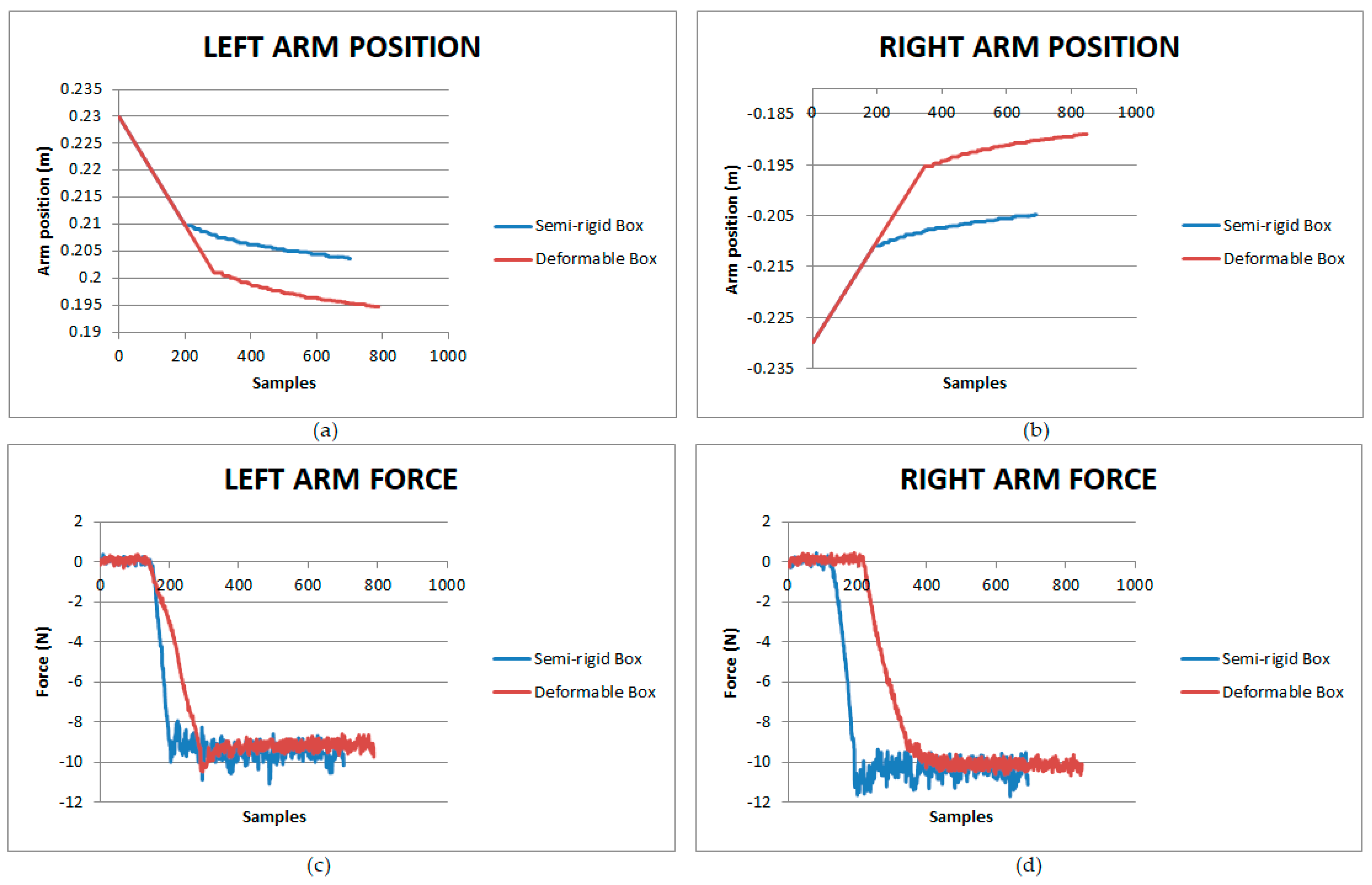
3.2.4. Semi-Rigid vs. Deformable Box Lifting
All the lifting experiments were conducted using a semi-rigid box with the internal structure shown in
Figure 9b. However, we cannot expect the same behavior when using a deformable box. In a real case, we may have to face this problem. For this reason, a last experiment comparing the lifting results for rigid and non-rigid boxes has been conducted. In this case, the weight was constant (again 1.35 Kg), and a simple feedback based on the position of the arms to maintain the force in the Z axis was applied. The main difference to be evaluated in this experiment is the consistency of the box. In one case, the structure is assembled, and in the second case, to maintain the same weight, the structure inside the box is disassembled.
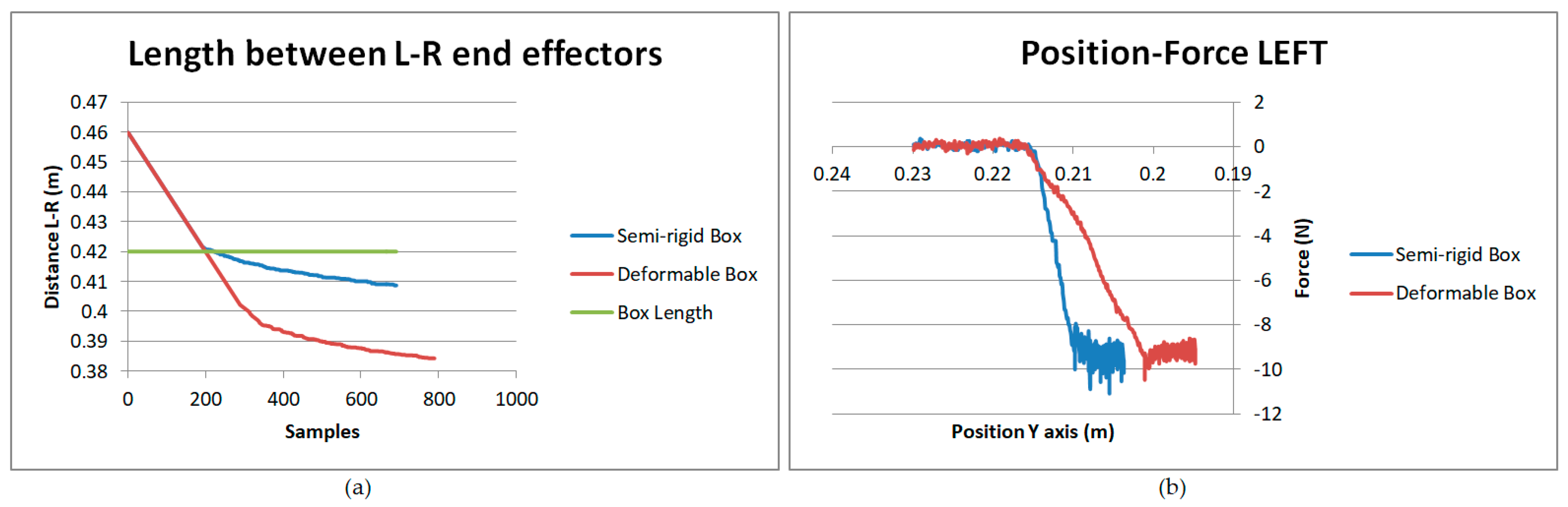
As shown in
Figure 13, we can find some similarities and differences between each case. The displacement of the arms (
Figure 13a,b) in the case of the deformable box is higher than that in the case of the semi-rigid box. This extra displacement appears due to the deformation caused in the lateral faces of the box. The vertical increase in the graphs is produced due to the displacement of the arms needed to reach the calculated force. However, the almost vertical side of the graph represents the correction made by the arms while lifting the box to keep the forces constant. If we look at
Figure 14a, it can be seen that from the point of contact of both arms with the box, in the semi-rigid case, the deformation is just 5 mm per side. However, in the deformable case, to reach the required grasping force, the box is compressed to almost 25 mm per side.
Regarding the force (
Figure 13c,d), in both cases, despite the rigidity of the box, the force needed to lift the box is the same. However, the main difference between having a rigid and non-rigid box is the time that it takes the robot to reach the required force. When the box is almost rigid, the robot reaches the contact force with the surface more quickly than when it is deformable. This comparison of the response between both cases can also be seen in
Figure 14b, where the force depending on the left arm position is presented.
3.3. Spinning the Box
The last movement needed to manipulate a box is the action of spinning it over a surface. In this case, the forces from both end effectors are applied in the opposite corners of the box, as shown in
Figure 15. As shown in Equation (8), the bigger the distance “l” from the center of the box to the point where the force is applied, the lower the force required to make the movement.
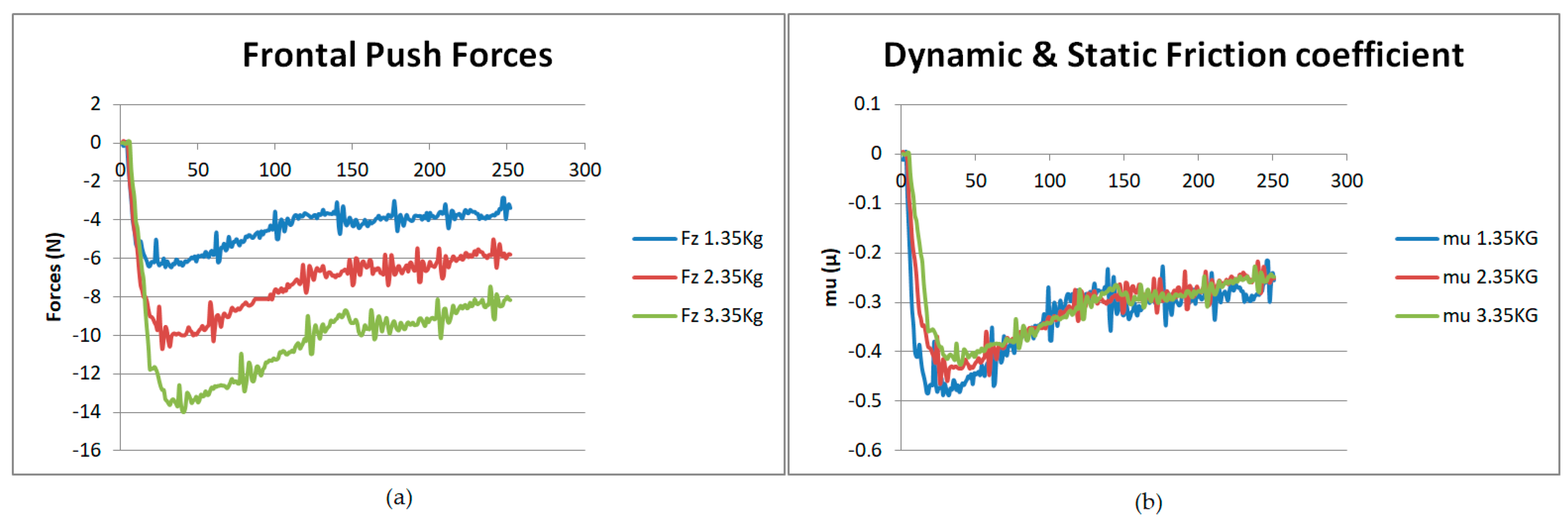
As in the lifting movement, the friction coefficient of the box over the steel sheet where it is lying is not known. For this reason, to obtain an estimation of this value, as the weight of the box can be a known value, the humanoid robot will push the same box in the frontal direction, with different masses inside: 1.35 Kg, 2.35 Kg and 3.35 Kg, as shown in
Figure 16a. Applying the friction force equation, and taking into account the force values obtained with the force sensor of the right hand of TEO,
Figure 16b, the static friction coefficient obtained to start the sliding movement of the box in the table (
) is equal to 0.4. Meanwhile, the dynamic friction coefficient (
) obtained as a result of the movement of the box over the steel sheet is 0.3.
In
Figure 17a, the trajectory followed by the left arm to spin the box on the steel surface is shown. The height of the end effector (Pos Z) was maintained, while X and Y were changed to describe a circular trajectory. In
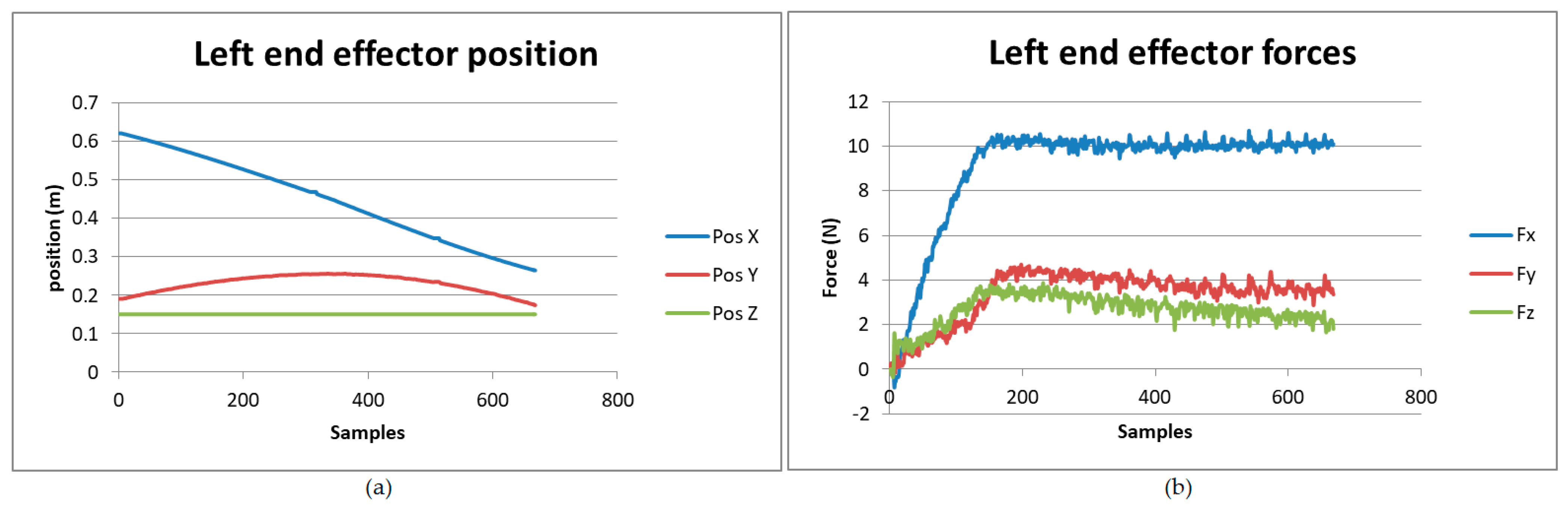
Figure 17b, the forces as a result of the spinning action can be seen. In this case, the main force is made in the x axis, insofar as the robot is pushing the box frontally to make the corner spin.
4. How Can Primitive Movements Be Used?
In the previous section, the force equations obtained for each of the three kinds of movements considered to bi-manipulate a box were checked by performing experiments in the laboratory with the humanoid robot, TEO, and capturing the information with the sensors available: encoders, an optical tracking system, and force sensors. However, one question still remains: how can this information be used to manipulate boxes? In this section, an explanation of the use of these data in the general application is provided. Additionally, a low-level use of the information in hybrid position–force control is described. Both, the general application and the hybrid position–force control are currently on-going works.
4.1. General Application
As it can be seen in
Figure 18, by using the vision system, the box is recognized by acquiring its position in space and dimensions, as well as its characteristics, such as logos, letters, or opening lines. Using this information, the robot attempts to find the opening side of the box. In Reference [
23], the visual information processing to obtain these characteristics and a first attempt to find the opening side of the box using decision trees are presented.
In this paper, the results have been centered on sensing the forces in the end effectors of the robot while performing three different tasks. As a result of these movements, the repeatability of the results could be seen. In the general application, this behavior, together with the dimensions and position of the box obtained by vision will be used to adapt these movement patterns to different kinds of boxes. In the case of the lifting movement, reinforcement learning will be used, so the robot can decide if the box is successfully lifted based on a pattern comparison.
Finally, by combining the movement patterns adapted to the different boxes, along with the logos, letters, etc., reinforcement learning is used to set the movement sequence to find the opening side of the box. This sequence is performed by TEO, which applies a hybrid position–force control, which is explained in the following subsection.
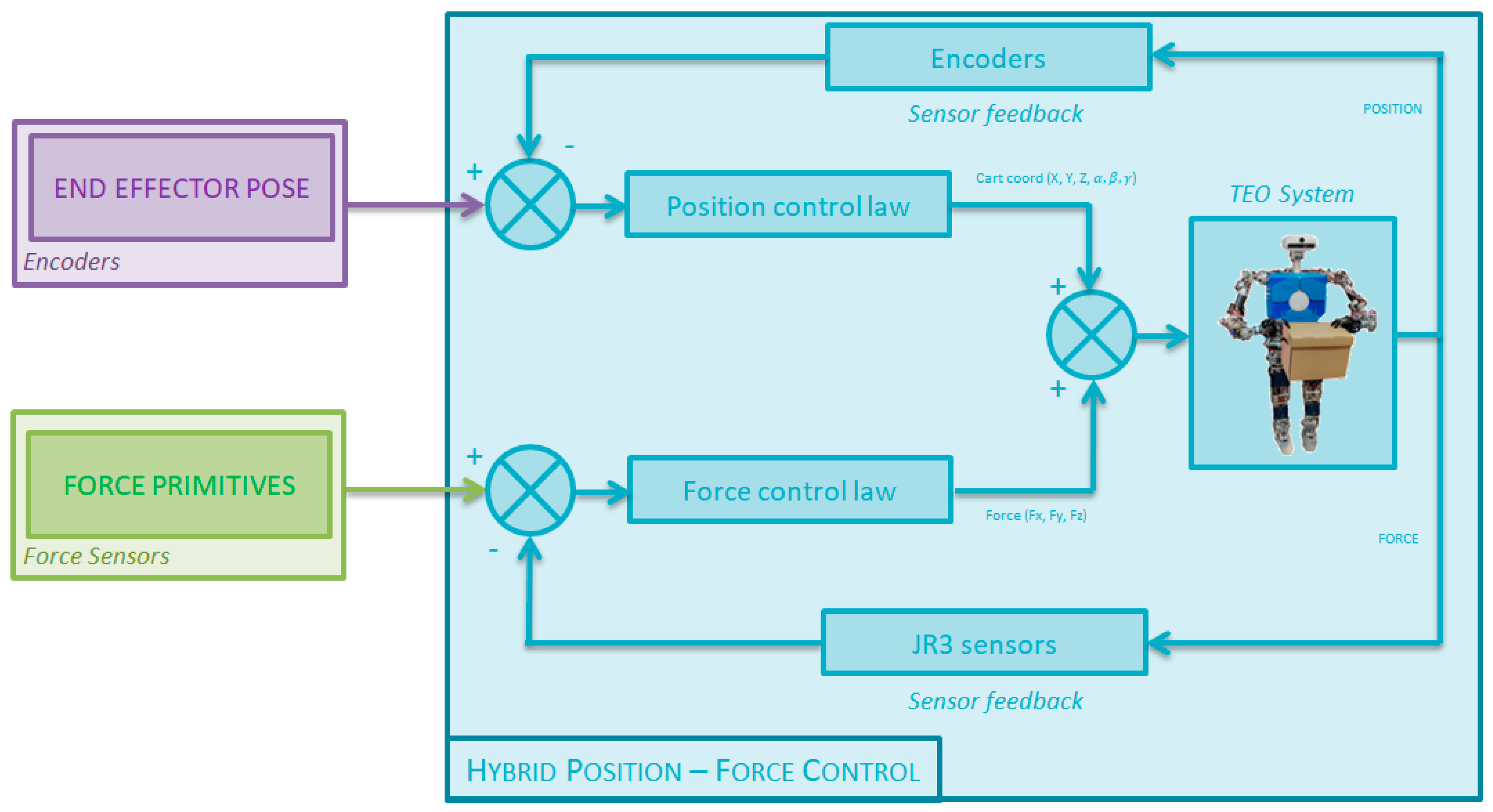
4.2. Hybrid Position–Force Control
In
Figure 19, the scheme according of the hybrid position–force control can be seen. The inputs introduced in the system are: the position of the arm in each point of the movement and the primitive force equations adapted to the characteristics of the box.
Then, the position and force data are checked in their respective control laws, giving as an output the cartesian coordinates of the robot end effectors, as well as the expected forces for that movement. These control outputs are combined to command the movements with the Humanoid Robot, TEO. To check if these trajectories are being followed, the force sensors and the encoders from the robot arm articulations will be used to close the loop. In case any error is detected, the required corrections will be applied to approximate the movements as much as possible to the primitive force equations and to the expected positions of the arms.
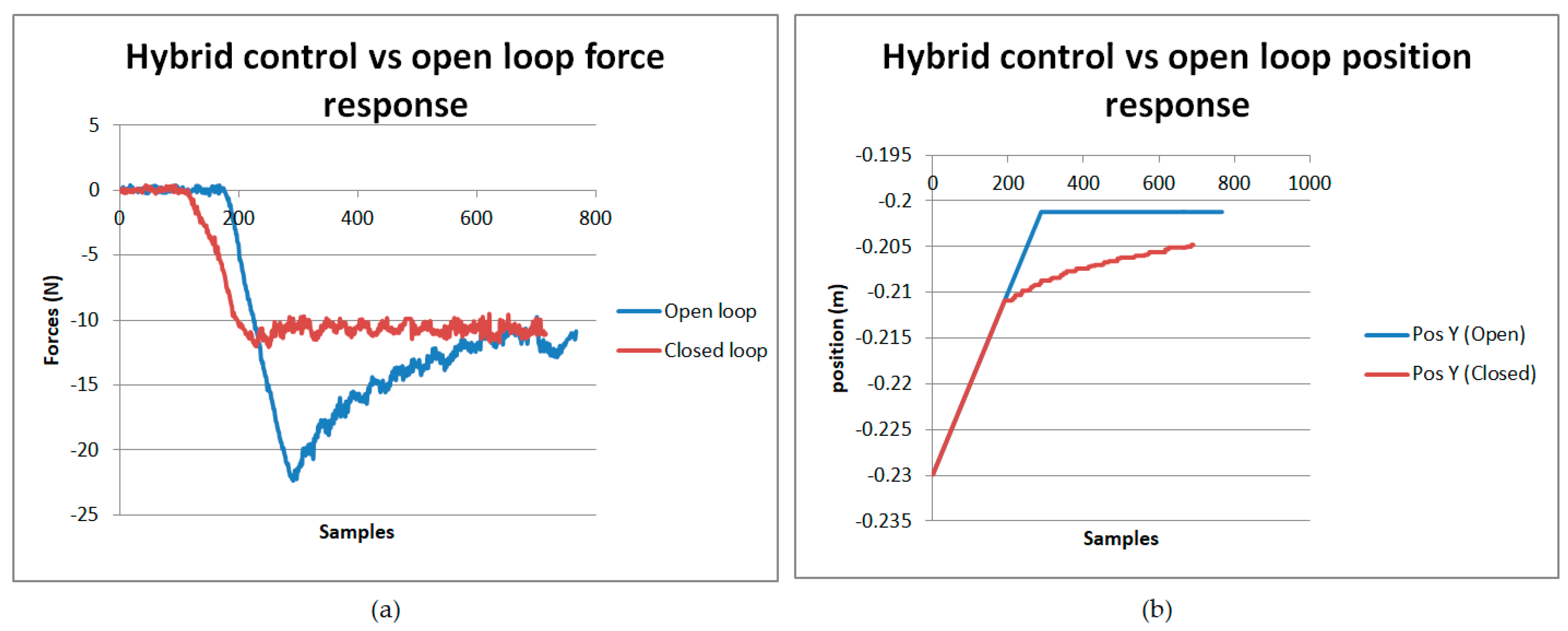
A first approach of the hybrid control has been implemented in the lifting task. As can be seen in
Figure 20a, in the closed loop, the force needed to lift the box is significantly lower. As the force is constant during the movement, and there is no loss, it is not needed to apply 20 N at the beginning. As a consequence, the force is equal to 10 N during the entire movement. To achieve this, a change in the position of the arm is required, as shown in
Figure 20b. In the case where the loop is open, the arm has a higher displacement in the approximation stage (more pressure applied in the beginning). However, once the target force is reached, during the lifting, there is no displacement. Instead, with the hybrid control, the end effector in the first stage has a lower movement (less force applied, at just 10 N). Then, during the lifting movement, the arm moves to keep the value constant.
5. Conclusions and Future Work
In this paper, three different strategies to bi-manipulate a box were studied: overturning, lifting, and spinning. In the three cases, the force equations were firstly calculated, then checked with different experimental procedures defined for each of the movements.
The overturning movement has been characterized, identifying four stages of the forces involved during the motion of the action. The theoretical horizontal forces needed to overturn the box during the third stage were calculated with Equation (3). Then, the results of the experiments were compared with the theoretic calculus, finding a similar behavior. As a consequence, the equation will be used as a primitive for the hybrid position–force control.
In the lifting experiments, the variation of the end-effector force sensor readings, depending on different variables, was studied. Firstly, the robot repeatedly attempted to lift a constant known weight by changing the friction coefficient. Once the friction coefficient was chosen, the lifting movement was made, using different weights to validate it. After performing successful and failed lifting attempts, the forces in the Z and Y axes were studied. A pattern in the relation between these forces was repeated when the action was successfully completed. These patterns will be used to train a reinforcement learning system. Thus, the robot will be capable of determining when the box has been lifted without visual feedback.
Additionally, based on the comparison of lifting semi-rigid and deformable boxes, we determined that the final force needed to grasp a box is the same, varying only the position of the end effectors in each case.
Finally, the box has been frontally pushed to check the friction coefficient in relation to a steel surface. Then, in the spinning experiments, the composition of the force applied in the three axes, depending on the position of the end effector, was captured by the force sensors and the encoders.
In future works, the primitive movements obtained in this paper will be implemented, following the hybrid control presented in section IV. The hybrid control will be the basis for a type of reinforcement learning, in which experiments with different kinds of boxes and weights will be performed to acquire information about the successful manipulation of boxes. These experiments will add data for the optimization of trajectories and movements.


 ,
, 


