
Performance Tradeoff Analysis of Hybrid Signaling SWIPT Systems with Nonlinear Power Amplifiers

 , ,
, ,
Abstract
:1. Introduction
2. System Model
2.1. Memoryless Nonlinear PA Models
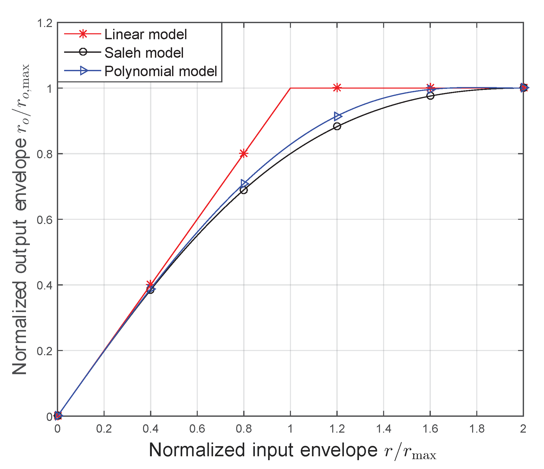
2.1.1. Ideal Linear PA Model
2.1.2. Saleh Model
2.1.3. Memoryless Polynomial Model
2.2. Input Power Back-Off
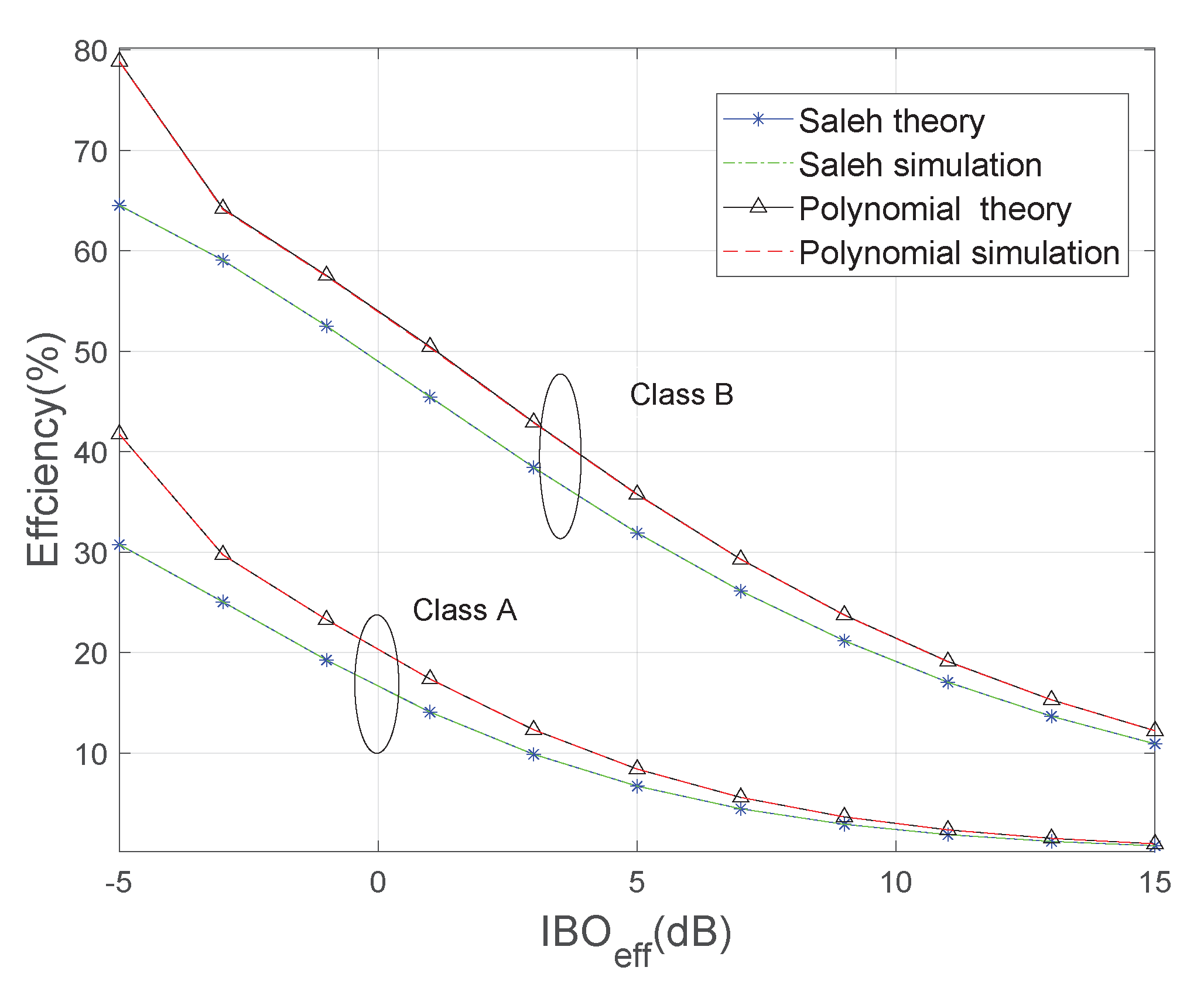
3. Calculation of PA Efficiency
4. SNDR Analysis
4.1. Identical Amplification Coefficient
4.2. Different Amplification Coefficients
5. Numerical Results and Discussion
6. Conclusions
Author Contributions
Funding
Acknowledgments
Conflicts of Interest
Appendix A
References
- Yang, Z.; Chen, M.; Wong, K.K.; Poor, H.V.; Cui, S. Federated Learning for 6G: Applications, Challenges, and Opportunities. arXiv 2021, arXiv:2101.01338. [Google Scholar]
- Hu, J.; Li, M.; Yang, K.; Ng, S.X.; Wong, K.K. Unary coding controlled simultaneous wireless information and power transfer. IEEE Trans. Wirel. Commun. 2019, 19, 637–649. [Google Scholar] [CrossRef]
- Li, A.; Masouros, C. Energy-efficient SWIPT: From fully digital to hybrid analog–digital beamforming. IEEE Trans. Veh. Technol. 2017, 67, 3390–3405. [Google Scholar] [CrossRef]
- Choi, B.H.; Thai, V.X.; Lee, E.S.; Kim, J.H.; Rim, C.T. Dipole-coil-based wide-range inductive power transfer systems for wireless sensors. IEEE Trans. Ind. Electron. 2016, 63, 3158–3167. [Google Scholar] [CrossRef]
- Atallah, R.F.; Assi, C.M.; Yu, J.Y. A reinforcement learning technique for optimizing downlink scheduling in an energy-limited vehicular network. IEEE Trans. Veh. Technol. 2016, 66, 4592–4601. [Google Scholar] [CrossRef]
- Hu, J.; Yang, K.; Wen, G.; Hanzo, L. Integrated data and energy communication network: A comprehensive survey. IEEE Commun. Surv. Tutor. 2018, 20, 3169–3219. [Google Scholar] [CrossRef] [Green Version]
- Varshney, L.R. Transporting information and energy simultaneously. In Proceedings of the 2008 IEEE International Symposium on Information Theory, Toronto, ON, Canada, 6–11 July 2008; pp. 1612–1616. [Google Scholar]
- Huang, G.; Zhang, Q.; Qin, J. Joint time switching and power allocation for multicarrier decode-and-forward relay networks with SWIPT. IEEE Signal Process. Lett. 2015, 22, 2284–2288. [Google Scholar] [CrossRef]
- Dong, Y.; Hossain, M.J.; Cheng, J. Joint power control and time switching for SWIPT systems with heterogeneous QoS requirements. IEEE Commun. Lett. 2015, 20, 328–331. [Google Scholar] [CrossRef]
- Krikidis, I.; Timotheou, S.; Nikolaou, S.; Zheng, G.; Ng, D.W.K.; Schober, R. Simultaneous wireless information and power transfer in modern communication systems. IEEE Commun. Mag. 2014, 52, 104–110. [Google Scholar] [CrossRef] [Green Version]
- Zhou, X. Training-based SWIPT: Optimal power splitting at the receiver. IEEE Trans. Veh. Technol. 2014, 64, 4377–4382. [Google Scholar] [CrossRef] [Green Version]
- Ding, Z.; Perlaza, S.M.; Esnaola, I.; Poor, H.V. Power allocation strategies in energy harvesting wireless cooperative networks. IEEE Trans. Wirel. Commun. 2014, 13, 846–860. [Google Scholar] [CrossRef] [Green Version]
- Chen, H.; Li, Y.; Jiang, Y.; Ma, Y.; Vucetic, B. Distributed power splitting for SWIPT in relay interference channels using game theory. IEEE Trans. Wirel. Commun. 2014, 14, 410–420. [Google Scholar] [CrossRef] [Green Version]
- Abedi, M.; Masoumi, H.; Emadi, M.J. Power splitting-based SWIPT systems with decoding cost. IEEE Wirel. Commun. Lett. 2018, 8, 432–435. [Google Scholar] [CrossRef]
- Guo, S.; Zhang, H.; Wang, Y.; Yuan, D. Spatial modulated simultaneous wireless information and power transfer. In Proceedings of the 2016 IEEE Global Communications Conference (GLOBECOM), Washington, DC, USA, 4–8 December 2016; pp. 1–6. [Google Scholar]
- Koo, B.; Park, D. Interference alignment and wireless energy transfer via antenna selection. IEEE Commun. Lett. 2014, 18, 548–551. [Google Scholar] [CrossRef]
- Zhao, S.; Li, Q.; Zhang, Q.; Qin, J. Antenna selection for simultaneous wireless information and power transfer in MIMO systems. IEEE Commun. Lett. 2014, 18, 789–792. [Google Scholar] [CrossRef]
- Jang, H.H.; Choi, K.W.; Kim, D.I. Novel frequency-splitting SWIPT for overcoming amplifier nonlinearity. IEEE Wirel. Commun. Lett. 2020, 9, 826–829. [Google Scholar] [CrossRef]
- Clerckx, B.; Zhang, R.; Schober, R.; Ng, D.W.K.; Kim, D.I.; Poor, H.V. Fundamentals of Wireless Information and Power Transfer: From RF Energy Harvester Models to Signal and System Designs. IEEE J. Sel. Areas Commun. 2019, 37, 4–33. [Google Scholar] [CrossRef] [Green Version]
- Boshkovska, E.; Ng, D.W.K.; Zlatanov, N.; Schober, R. Practical Non-Linear Energy Harvesting Model and Resource Allocation for SWIPT Systems. IEEE Commun. Lett. 2015, 19, 2082–2085. [Google Scholar] [CrossRef] [Green Version]
- Guerreiro, J.; Dinis, R.; Montezuma, P. On the Assessment of Nonlinear Distortion Effects in MIMO-OFDM Systems. In Proceedings of the IEEE 83rd Vehicular Technology Conference (VTC Spring), Nanjing, China, 15–18 May 2016; pp. 1–5. [Google Scholar]
- Ozel, O.; Ulukus, S. Achieving AWGN capacity under stochastic energy harvesting. IEEE Trans. Inf. Theory 2012, 58, 6471–6483. [Google Scholar] [CrossRef] [Green Version]
- Ozel, O.; Ulukus, S. AWGN channel under time-varying amplitude constraints with causal information at the transmitter. In Proceedings of the 2011 Conference Record of the Forty Fifth Asilomar Conference on Signals, Systems and Computers (ASILOMAR), Pacific Grove, CA, USA, 6–9 November 2011; pp. 373–377. [Google Scholar]
- Tutuncuoglu, K.; Ozel, O.; Yener, A.; Ulukus, S. Binary energy harvesting channel with finite energy storage. In Proceedings of the 2013 IEEE International Symposium on Information Theory, Istanbul, Turkey, 7–12 July 2013; pp. 1591–1595. [Google Scholar]
- Xiong, K.; Wang, B.; Liu, K.R. Rate-energy region of SWIPT for MIMO broadcasting under nonlinear energy harvesting model. IEEE Trans. Wirel. Commun. 2017, 16, 5147–5161. [Google Scholar] [CrossRef]
- Niu, H.; Guo, D.; Huang, Y.; Zhang, B. Robust energy efficiency optimization for secure MIMO SWIPT systems with non-linear EH model. IEEE Commun. Lett. 2017, 21, 2610–2613. [Google Scholar] [CrossRef]
- Zhang, R.; Ho, C.K. MIMO broadcasting for simultaneous wireless information and power transfer. IEEE Trans. Wirel. Commun. 2013, 12, 1989–2001. [Google Scholar] [CrossRef] [Green Version]
- Hu, Z.; Yuan, C.; Gao, F. Maximizing harvested energy for full-duplex SWIPT system with power splitting. IEEE Access 2017, 5, 24975–24987. [Google Scholar] [CrossRef]
- Jiang, R.; Xiong, K.; Fan, P.; Zhang, Y.; Zhong, Z. Optimal design of SWIPT systems with multiple heterogeneous users under non-linear energy harvesting model. IEEE Access 2017, 5, 11479–11489. [Google Scholar] [CrossRef]
- Zhou, X.; Zhang, R.; Ho, C.K. Wireless information and power transfer: Architecture design and rate-energy tradeoff. IEEE Trans. Commun. 2013, 61, 4754–4767. [Google Scholar] [CrossRef] [Green Version]
- Zhao, Y.; Hu, J.; Ding, Z.; Yang, K. Joint interleaver and modulation design for multi-user SWIPT-NOMA. IEEE Trans. Commun. 2019, 67, 7288–7301. [Google Scholar] [CrossRef] [Green Version]
- Perera, T.D.P.; Jayakody, D.N.K.; Sharma, S.K.; Chatzinotas, S.; Li, J. Simultaneous wireless information and power transfer (SWIPT): Recent advances and future challenges. IEEE Commun. Surv. Tutor. 2017, 20, 264–302. [Google Scholar] [CrossRef] [Green Version]
- Pan, C.; Ren, H.; Wang, K.; Elkashlan, M.; Nallanathan, A.; Wang, J.; Hanzo, L. Intelligent Reflecting Surface Aided MIMO Broadcasting for Simultaneous Wireless Information and Power Transfer. IEEE J. Sel. Areas Commun. 2020, 38, 1719–1734. [Google Scholar] [CrossRef]
- Bai, T.; Pan, C.; Ren, H.; Deng, Y.; Elkashlan, M.; Nallanathan, A. Resource Allocation for Intelligent Reflecting Surface Aided Wireless Powered Mobile Edge Computing in OFDM Systems. IEEE Trans. Wirel. Commun. 2021. [Google Scholar] [CrossRef]
- Pan, Y.; Wang, K.; Pan, C.; Zhu, H.; Wang, J. Self-Sustainable Reconfigurable Intelligent Surface Aided Simultaneous Terahertz Information and Power Transfer (STIPT). arXiv 2021, arXiv:2102.04053. [Google Scholar]
- Ni, R.; Mayaram, K.; Fiez, T.S. A 915 MHz, 6 Mb/s, 80 pJ/b BFSK receiver with- 76dBm sensitivity for high data rate wireless sensor networks. In Proceedings of the 2014 Symposium on VLSI Circuits Digest of Technical Papers, Honolulu, HI, USA, 10–13 June 2014; pp. 1–2. [Google Scholar]
- Chatterjee, S.; Tarique, M. A 100-nW sensitive RF-to-DC CMOS rectifier for energy harvesting applications. In Proceedings of the 2016 29th International Conference on VLSI Design and 2016 15th International Conference on Embedded Systems (VLSID), Kolkata, India, 4–8 January 2016; pp. 557–558. [Google Scholar]
- Clerckx, B. Wireless information and power transfer: Nonlinearity, waveform design, and rate-energy tradeoff. IEEE Trans. Signal Process. 2017, 66, 847–862. [Google Scholar] [CrossRef] [Green Version]
- Claessens, S.; Chang, Y.T.; Schreurs, D.; Pollin, S. Receiving ASK-OFDM in Low Power SWIPT Nodes without Local Oscillators. In Proceedings of the 2019 IEEE Wireless Power Transfer Conference (WPTC), London, UK, 18–21 June 2019; pp. 20–25. [Google Scholar]
- Collado, A.; Georgiadis, A. Optimal waveforms for efficient wireless power transmission. IEEE Microw. Wirel. Compon. Lett. 2014, 24, 354–356. [Google Scholar] [CrossRef]
- Claessens, S.; Rajabi, M.; Pan, N.; Pollin, S.; Schreurs, D. Measurement-based analysis of the throughput-power level trade-off with modulated multisine signals in a SWIPT system. In Proceedings of the 2017 89th ARFTG Microwave Measurement Conference (ARFTG), Honololu, HI, USA, 9 June 2017; pp. 1–4. [Google Scholar]
- Clerckx, B.; Bayguzina, E. Waveform design for wireless power transfer. IEEE Trans. Signal Process. 2016, 64, 6313–6328. [Google Scholar] [CrossRef] [Green Version]
- Ikeuchi, T.; Kawahara, Y. Signal Detection Method Based on Peak to Average Ratio for Frequency Shift Multitone SWIPT System. In Proceedings of the 2020 IEEE Wireless Power Transfer Conference (WPTC), Seoul, Korea, 15–19 November 2020; pp. 119–122. [Google Scholar]
- Lu, Y.; Xiong, K.; Fan, P.; Zhong, Z.; Letaief, K.B. Robust transmit beamforming with artificial redundant signals for secure SWIPT system under non-linear EH model. IEEE Trans. Wirel. Commun. 2018, 17, 2218–2232. [Google Scholar] [CrossRef]
- Huang, X.; Li, Q.; Zhang, Q.; Qin, J. Power allocation for secure OFDMA systems with wireless information and power transfer. Electron. Lett. 2014, 50, 229–230. [Google Scholar] [CrossRef]
- Kim, I.M.; Kim, D.I.; Kang, J.M. Rate-energy tradeoff and decoding error probability-energy tradeoff for SWIPT in finite code length. IEEE Trans. Wirel. Commun. 2017, 16, 8220–8234. [Google Scholar] [CrossRef]
- Yang, Z.; Xu, W.; Pan, Y.; Pan, C.; Chen, M. Energy Efficient Resource Allocation in Machine-to-Machine Communications With Multiple Access and Energy Harvesting for IoT. IEEE Internet Things J. 2018, 5, 229–245. [Google Scholar] [CrossRef]
- Ma, W.; Li, C.; Quan, X.; Pan, W.; Xu, Q.; Liu, Y.; Tang, Y. A Nonlinear Feedback Linearized Power Amplifier for Wireless Communication Systems. In Proceedings of the 2018 IEEE International Symposium on Signal Processing and Information Technology (ISSPIT), Louisville, KY, USA, 6–8 December 2018; pp. 241–246. [Google Scholar]
- Iofedov, I.; Wulich, D. MIMO–OFDM with nonlinear power amplifiers. IEEE Trans. Commun. 2015, 63, 4894–4904. [Google Scholar] [CrossRef]
- Kim, J.; Clerckx, B.; Mitcheson, P.D. Experimental analysis of harvested energy and throughput trade-off in a realistic SWIPT system. In Proceedings of the 2019 IEEE Wireless Power Transfer Conference (WPTC), London, UK, 18–21 June 2019; pp. 1–5. [Google Scholar]
- Lavrador, P.M.; de Carvalho, N.B.; Pedro, J.C. Evaluation of signal-to-noise and distortion ratio degradation in nonlinear systems. IEEE Trans. Microw. Theory Tech. 2004, 52, 813–822. [Google Scholar] [CrossRef]
- Raab, F.H.; Asbeck, P.; Cripps, S.; Kenington, P.B.; Popovic, Z.B.; Pothecary, N.; Sevic, J.F.; Sokal, N.O. Power amplifiers and transmitters for RF and microwave. IEEE Trans. Microw. Theory Tech. 2002, 50, 814–826. [Google Scholar] [CrossRef] [Green Version]
- Ochiai, H. An analysis of band-limited communication systems from amplifier efficiency and distortion perspective. IEEE Trans. Commun. 2013, 61, 1460–1472. [Google Scholar] [CrossRef]
- Saleh, A.A.; Salz, J. Adaptive linearization of power amplifiers in digital radio systems. Bell Syst. Tech. J. 1983, 62, 1019–1033. [Google Scholar] [CrossRef]
- Joung, J.; Ho, C.K.; Adachi, K.; Sun, S. A survey on power-amplifier-centric techniques for spectrum-and energy-efficient wireless communications. IEEE Commun. Surv. Tutor. 2014, 17, 315–333. [Google Scholar] [CrossRef]
- Vuolevi, J.H.; Rahkonen, T.; Manninen, J.P. Measurement technique for characterizing memory effects in RF power amplifiers. IEEE Trans. Microw. Theory Tech. 2001, 49, 1383–1389. [Google Scholar] [CrossRef]
- Golestaneh, H.; Abdipour, A.; Mohammadi, A. Nonlinear modeling and analysis of a Doherty power amplifier driven by non-constant envelope signals. Analog Integr. Circuits Signal Process. 2012, 72, 141–153. [Google Scholar] [CrossRef]
- Taghian, F.; Abdipour, A.; Mohammadi, A.; Roodaki, P.M. Design and nonlinear analysis of a dual-band Doherty power amplifier for ISM and LMDS applications. In Proceedings of the 2011 IEEE Applied Electromagnetics Conference (AEMC), Kolkata, India, 18–22 December 2011; pp. 1–4. [Google Scholar]
- Wang, F.; Yang, A.H.; Kimball, D.F.; Larson, L.E.; Asbeck, P.M. Design of wide-bandwidth envelope-tracking power amplifiers for OFDM applications. IEEE Trans. Microw. Theory Tech. 2005, 53, 1244–1255. [Google Scholar] [CrossRef]
- Yang, Y.; Cha, J.; Shin, B.; Kim, B. A microwave Doherty amplifier employing envelope tracking technique for high efficiency and linearity. IEEE Microw. Wirel. Compon. Lett. 2003, 13, 370–372. [Google Scholar] [CrossRef]
- Wulich, D. Definition of efficient PAPR in OFDM. IEEE Commun. Lett. 2005, 9, 832–834. [Google Scholar] [CrossRef]
- Bassam, S.A.; Helaoui, M.; Ghannouchi, F.M. 2-D Digital Predistortion (2-D-DPD) Architecture for Concurrent Dual-Band Transmitters. IEEE Trans. Microw. Theory Tech. 2011, 59, 2547–2553. [Google Scholar] [CrossRef]
- Zhao, C.; Baxley, R.J.; Zhou, G.T. SNDR Analysis for Transceiver Nonlinearities in AWGN Channels. In Proceedings of the 2007 IEEE/SP 14th Workshop on Statistical Signal Processing, Madison, WI, USA, 26–29 August 2007; pp. 522–526. [Google Scholar]
- Zillmann, P. Relationship between Two Distortion Measures for Memoryless Nonlinear Systems. IEEE Signal Process. Lett. 2010, 17, 917–920. [Google Scholar] [CrossRef]
- Qian, H.; Raich, R.; Zhou, G. Optimization of SNDR in the presence of amplitude limited nonlinearity and multipath fading. In Proceedings of the Conference Record of the Thirty-Eighth Asilomar Conference on Signals, Systems and Computers, Pacific Grove, CA, USA, 7–10 November 2004; Volume 1, pp. 712–716. [Google Scholar]


| Power Ratio | Class A | Class B | |||||||||
|---|---|---|---|---|---|---|---|---|---|---|---|
| Saleh PA | Polynomial PA | Saleh PA | Polynomial PA | ||||||||
| SNDR (dB) | |||||||||||
| 10 | 20 | 10 | 20 | 10 | 20 | 30 | 10 | 20 | 30 | ||
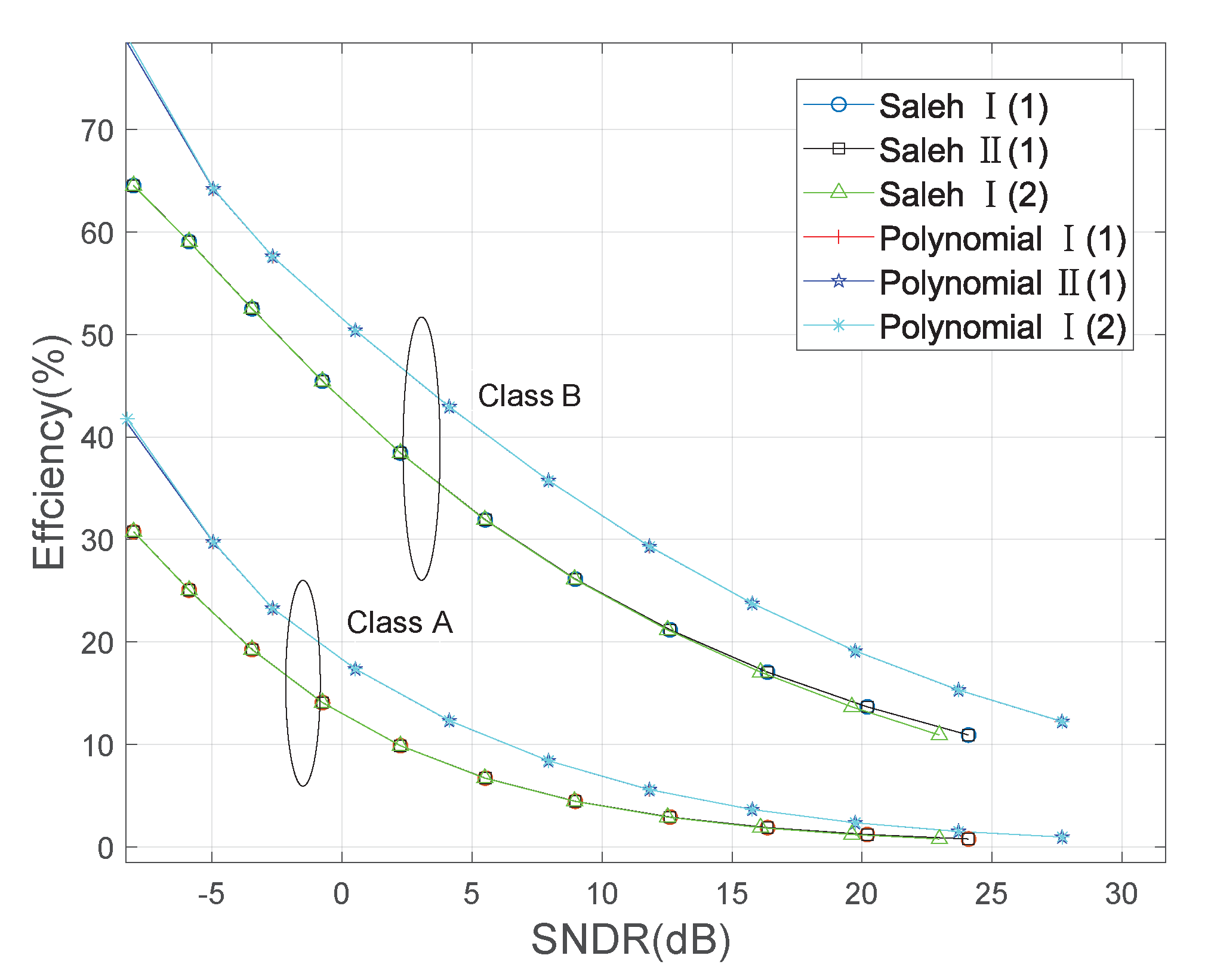
| 4 | Efficiency (%) | 14.4 | 4.5 | 20.7 | 8.1 | 45.9 | 26.1 | 14.2 | 54.3 | 34.8 | 20.1 |
| 16 | 7.8 | 2.4 | 12.3 | 4.7 | 35.1 | 19.4 | 10.9 | 42.9 | 26.6 | 15.1 | |
| 64 | 4.2 | 1.2 | 6.8 | 2.3 | 24.9 | 13.6 | - | 32.5 | 18.9 | - | |
| 256 | 1.9 | - | 3.6 | 1.0 | 17.1 | - | - | 23.7 | 13.8 | - | |
Publisher’s Note: MDPI stays neutral with regard to jurisdictional claims in published maps and institutional affiliations. |
© 2021 by the authors. Licensee MDPI, Basel, Switzerland. This article is an open access article distributed under the terms and conditions of the Creative Commons Attribution (CC BY) license (https://creativecommons.org/licenses/by/4.0/).
Share and Cite
Chen, L.; Wu, X.; Wang, X.; Qi, W.; Hong, X.; Shi, J.; Hu, J.; Yang, K. Performance Tradeoff Analysis of Hybrid Signaling SWIPT Systems with Nonlinear Power Amplifiers. Electronics 2021, 10, 1364. https://0-doi-org.brum.beds.ac.uk/10.3390/electronics10111364
Chen L, Wu X, Wang X, Qi W, Hong X, Shi J, Hu J, Yang K. Performance Tradeoff Analysis of Hybrid Signaling SWIPT Systems with Nonlinear Power Amplifiers. Electronics. 2021; 10(11):1364. https://0-doi-org.brum.beds.ac.uk/10.3390/electronics10111364
Chicago/Turabian StyleChen, Linlin, Xiaofang Wu, Xin Wang, Wen Qi, Xuemin Hong, Jianghong Shi, Jie Hu, and Kun Yang. 2021. "Performance Tradeoff Analysis of Hybrid Signaling SWIPT Systems with Nonlinear Power Amplifiers" Electronics 10, no. 11: 1364. https://0-doi-org.brum.beds.ac.uk/10.3390/electronics10111364