
Improved Droop Control Strategy of Multiple Energy Storage Applications in an AC Microgrid Based on the State of Charge


School of Mechanical and Electrical Engineering, Guangzhou University, Guangzhou 510006, China
*
Author to whom correspondence should be addressed.
Electronics 2021, 10(14), 1726; https://0-doi-org.brum.beds.ac.uk/10.3390/electronics10141726
Submission received: 4 June 2021
/
Revised: 10 July 2021
/
Accepted: 16 July 2021
/
Published: 18 July 2021
(This article belongs to the Section Power Electronics)
Abstract
:Distributed energy storage technology is used to stabilize the frequency and voltage of the microgrid operating in islanded mode. However, due to the inconsistent state of charge (SoC) of the energy storage unit (ESU), the active power output of the ESU cannot be shared reasonably. On the basis of stabilizing voltage and frequency, this paper presents a power exponential function droop control (PEFDC) strategy considering the SoC. In this control strategy, the ESU is allowed to adjust the output power adaptively according to its own SoC level during discharge and reaches SoC equilibrium. Simulation models are built to compare the PEFDC strategy with conventional droop control (CDC) and power function droop control (PFDC) approaches. The simulation results illustrate the superiority of the proposed control strategy over the other two methods. Finally, the hardware-in-the-loop experiment is conducted to verify the effectiveness of the PEFDC strategy.
1. Introduction
The development and use of new energy sources have become trends for the present and the future, as the serious pollution caused by traditional energy sources has brought environmental problems to the fore. Distributed-based microgrids are attracting widespread interest, as they can better exploit the advantages of distributed power sources [1,2]. Distributed energy storage technology is an effective measure to meet the needs of new energy consumption and enhance the stability of the microgrid. Multiple energy storage units (ESUs) can be connected to the AC microgrid via inverters to expand the capacity of the microgrid [3,4,5]. Stabilizing the frequency of the AC microgrid is the basic task of various control strategies, and each ESU can be cut off or put in depending on the scale of the load, which improves the stability of the microgrid [6,7].
Due to the lack of support from the large power grid, the voltage and frequency of an AC microgrid in islanded mode tend to fluctuate and an effective control strategy is required [8,9,10]. When faults and load variations occur, distributed ESUs will adjust their outputs to stabilize the system frequency so that the power quality is guaranteed. Most of the distributed ESUs are connected to the microgrid through converters for capacity expansion. The main control strategies for ESUs include PQ control, droop control, constant voltage control, etc. [11,12,13,14]. Droop control has many advantages, such as easy implementation and a plug-and-play feature. Therefore, it is widely used in islanded microgrids [15,16,17]. The conventional droop control strategy ignores the existence of line impedance, resulting in deviations in power output of the ESUs. In extreme cases, large circulating currents will occur between the ESUs, affecting the stable operation of the system [1,18]. In addition, the power is not shared rationally among ESUs because the conventional droop control does not take the SoC of the batteries into account. In Ref. [19], the multiple of frequency and the differential of the DC-side voltage deviation are introduced to the droop strategy. The system inertia is increased and the dynamic performance of the system is improved. However, the stability of the system decreases significantly in the case of large load fluctuations. The multiple operating modes of the converter are integrated into a single functional loop in Ref. [20], which enhances the stability of the system and reduces transient fluctuations during mode switching. In Ref. [21], a power function droop control based on SoC is proposed, but the method is applied to DC microgrids. In Ref. [22], a simple relationship between droop coefficient and charge state is constructed by introducing SoC directly in the droop coefficient. However, the results show that the control effect needs to be improved. Similarly, a charge control strategy for energy storage based on SoC is investigated in Ref. [23]. In Ref. [24], a charge-state-based AC microgrid power control strategy is studied, which still provides good control performance when the SoC difference between the ESUs is small. Nonetheless, the shortcoming is that the transmission of the SoC reference value requires communication among the ESUs, which is in conflict with the plug-and-play principle. Moreover, the stability analysis is missed. Another droop control method considering the SoC of the battery is proposed in Ref. [25], where the ESU adjusts its output power depending on its SoC. However, the method is only available for ESUs with an SoC of more than 30%. The method introduces only one exponential factor, the size of which directly affects the amplitude of frequency fluctuation, the control performance is deteriorated due to the lack of constraints from other factors.
On the basis of research efforts reported in studies, this paper proposes a power exponential function droop control (PEFDC) strategy for multiple-ESU applications in an islanded microgrid based on the SoC of each ESU. The proposed method constructs an improved power exponential function between the SoC of ESU and the droop coefficient. Compared with other methods, this strategy not only stabilizes the AC bus voltage and the frequency when the load changes, but also enables each ESU to adjust its power output dynamically depending on its own SoC. The ESU with higher SoC produces more power and the one with lower SoC produces less power. Finally, reasonable sharing of power and SoC balance are achieved. Moreover, this droop method can work at low SoC and works by measuring local information, so communication is not required between ESUs.
The remainder of the paper is organized as follows: Section 2 illustrates the typical topology of the AC microgrid and the basic principle of the droop control. Section 3 introduces the proposed power exponential function droop control. Section 4 analyzes the stability by the small signal method. Section 5 gives the simulation and hardware-in-the-loop experiment results, several droop methods are compared and the design procedures of the factors are also discussed. Section 6 gives the conclusion.
2. AC Microgrid and Droop Control
2.1. System Structure
A typical topology of an AC microgrid is shown in Figure 1, where n multiple energy ESUs are connected to the AC bus via bidirectional DC/ac converters. The ac grid consists of ‘x’ DC sources and ‘y’ ac sources connected through DC/AC converters and AC/AC converters respectively, while AC loads are connected to the AC bus directly. The microgrid has two operation modes, i.e., grid-connected mode and islanded mode, which can be switched via a static transfer switch (STS). In grid-connected mode, the frequency and voltage of the AC microgrid are supported by the large grid and the power is shared among the micro-sources by means of power tracking [26]. Each micro-source operating in islanded mode supports the load independently and stabilizes the voltage and frequency of the microgrid to ensure the power quality when load variation occurs.
In islanded operation mode of the microgrid, the control strategy enables coordinated control of the charging and/or discharging of each ESU, which not only helps to stabilize the voltage and frequency, thus improving the power quality, but also allows each ESU to adjust its output active power in real time according to its own SoC. ESUs with high SoC deliver more power, while those with low SoC deliver less power. Eventually, power balance is achieved, namely, power is shared among the ESUs in a reasonable way, thus making the most of each ESU.
2.2. Droop Control of AC Microgrids
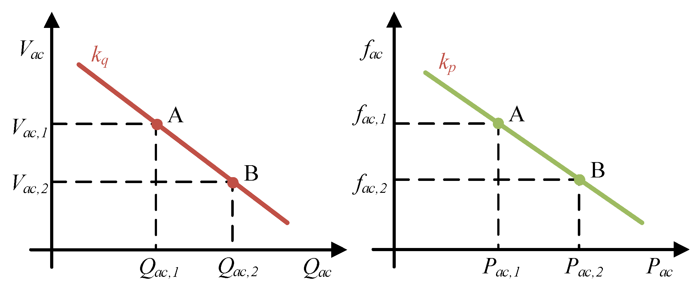
In AC microgrids, the use of simple conventional droop control in a distributed energy storage system allows the power to be shared proportionally according to the droop coefficients without communication [27]. The droop characteristic curve of an AC microgrid is shown in Figure 2, where the frequency and voltage droop coefficients are kp and kq, respectively. In steady state, the AC microgrid operates at Point A, where the voltage and frequency are Vac,1 and fac,1, respectively. When the load changes, the ESU can adjust the output power dynamically according to the droop characteristics. For example, when the load increases, the output power of the converter will increase, and this leads to decreases in frequency and voltage. The operating state will move from Point A to Point B. Therefore, the active and reactive power outputs of the converter can be adjusted by varying the values of the droop factors on the basis of frequency and voltage stability.
The equations of conventional droop control can be obtained as
where and are the actual frequency and voltage of the microgrid, respectively, and are the active and reactive power outputs of the converter after low-pass filtering, respectively, and are the reference values of frequency and voltage, respectively, and are the nominal powers of the converter, respectively, while and are the droop control coefficients, respectively.
3. Improved Droop Control Strategy for Distributed Energy Storage
3.1. Improved Droop Control Strategy
To solve the problem of unreasonable active power sharing in conventional droop control, this paper proposes an improved droop control strategy, which takes the state of charge of the ESU into account, and no communication is required among multiple ESUs to achieve reasonable sharing of the active power. The proposed control strategy constructs a power exponential function of the droop factor with the SoC of the ESU. The improved droop expression is
where m, n and p are the correction factors of the droop coefficient, and is the state of charge of the ith ESU. From Equation (3), the active power output of two paralleled ESUs during discharge is related to the SoC, and the ratio of the active power deviations is expressed as
As can be seen from Equation (4), the output power of the ESU is positively related to the battery’s SoC. The factors m, n and p mainly affect the rate of equilibrium and cause the system frequency fluctuation. The effects of these three factors are analyzed in detail below.
3.2. Mathematical Model of the System
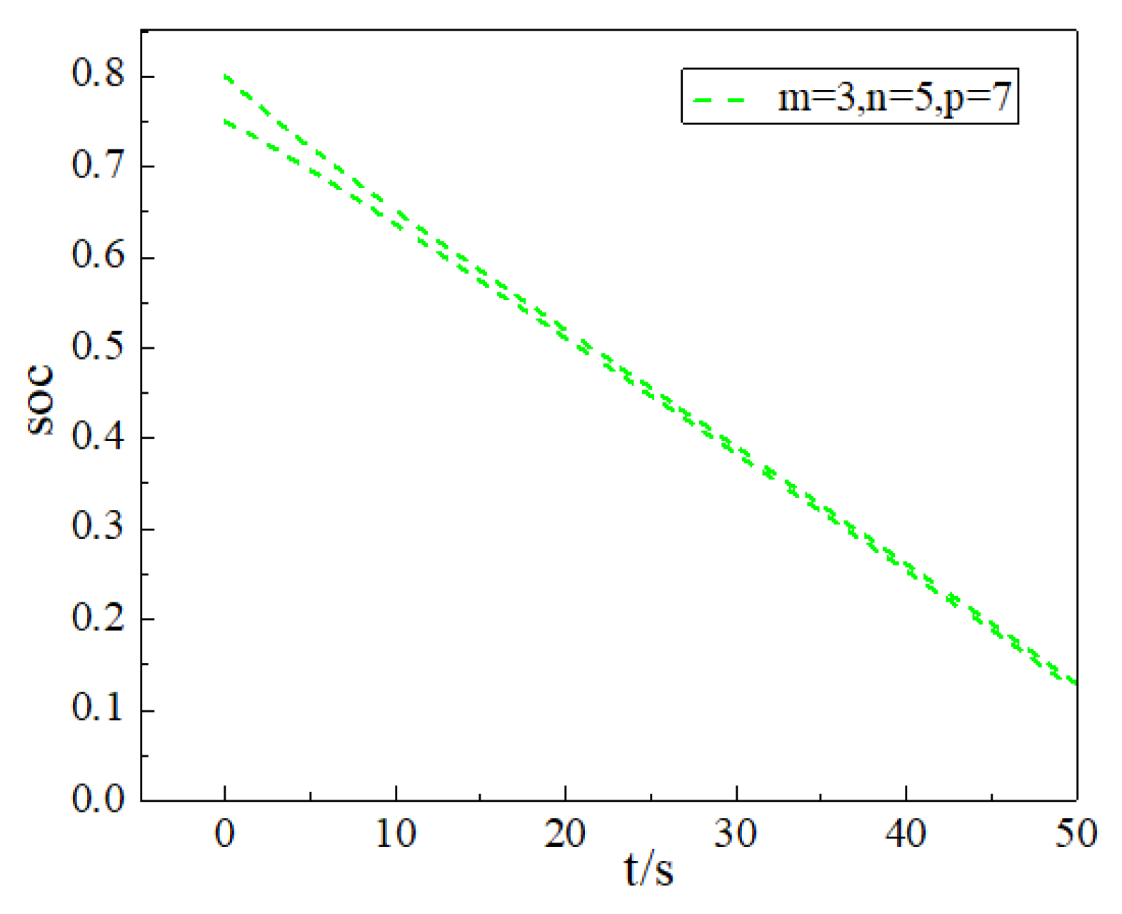
A mathematical model is developed to analyze the effect of the factors m, n and p on system frequency and load power sharing performance. The SoC estimation of lithium-ion batteries usually uses the coulomb counting method [28]; the calculation formula is
where is the initial charge state of the lithium battery.
The output power of the ESU is
where and are the output voltage and current of the lithium battery, respectively, is the capacity of the battery. So, the SoCs of the two batteries can be expressed as
Since the frequency is a global variable, it is clear from Equation (3) that the power output of the converter only depends on the droop coefficient, so Equations (7) and (8) can be further deduced as
where is the active power of the load. Mathematical simulations were carried out for Equations (9) and (10); the results are shown in Figure 3. As can be seen from the figure, the SoC of the two ESUs approach together gradually.
3.3. Proposed Converter Schemes
The detailed structure of the battery-dominated hybrid microgrid under islanded operation is shown in Figure 4. Energy storage batteries connect to the AC microgrid via DC/AC converters. LC filter is used at the output of each converter to improve the power quality. The load is connected directly to the AC bus.
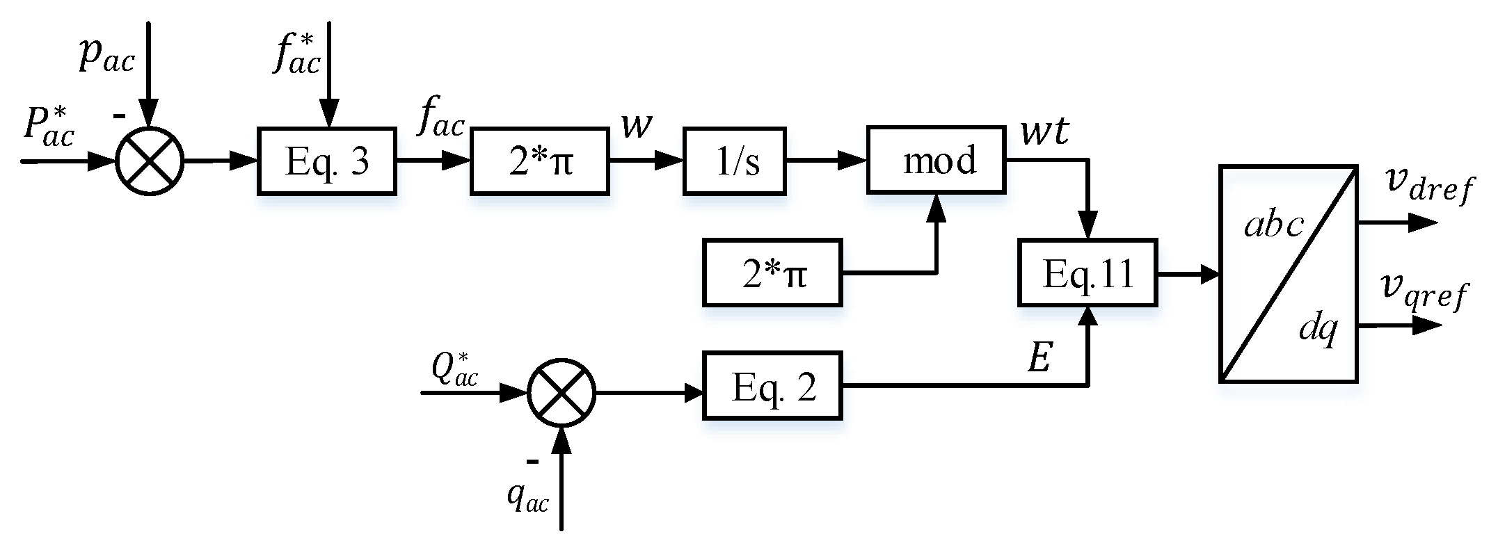
If the phase and amplitude of the voltage are known, the reference value of the voltage can be obtained by means of voltage composition:
Figure 5 shows the process of reference voltage generation, and the key is the phase angle and amplitude of the voltage, which can be obtained by Equations (2) and (3). They are known as frequency droop and voltage droop.
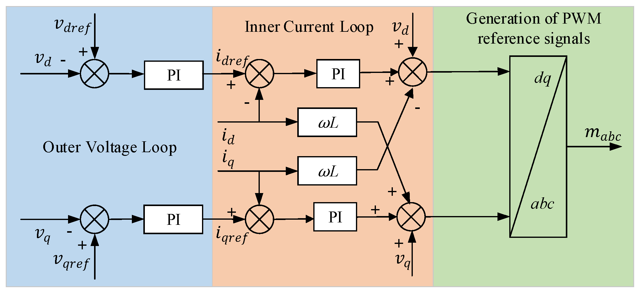
After obtaining the reference voltage, the d-axis and q-axis components under the stationary coordinate can be obtained by Park transformation. The d-axis voltage is coupled with the q-axis voltage. In order to facilitate the design of the controller and to achieve independent control, a front decoupling should be performed before the current controller. It should be noted that a large virtual impedance is added before obtaining the voltage reference values for the d and q axes to share the reactive power. The approximate decoupling of the converter output power is achieved by remodeling the equivalent output impedance without changing the control parameters. Figure 6 shows the structure of the voltage and current double closed-loop control, where the d-axis voltage is compared with the d-axis reference voltage and the error is sent to a PI controller to obtain the d-axis reference current. Then, the reference current is sent through the current inner-loop controller and the output is added to the d-axis voltage to obtain a reference control voltage, which is used as a reference signal for PWM.
4. Stability Analysis
4.1. Small Signal Stability Analysis
From Equation (3), the improved droop expressions for the two paralleled ESUs are obtained as
The small signal perturbations of and are
where the capital letters represent steady state quantities and the symbols with ‘’ mean small signal perturbation quantities.
Small signal perturbation is applied to Equations (7) and (8), the results in frequency domain are expressed as
The power from the ESU needs to be filtered by a low-pass filter:
where is the transfer function of a second-order low-pass filter:
where ξ is the damping coefficient and is the cut-off frequency. After eliminating and by substituting Equation (18) into Equations (16) and (17), we obtain
After substituting (20) into (14) and (21) into (15), and are eliminated:
To simplify Equations (22) and (23), set and as
Thus, Equations (22) and (23) can be expressed as
In a steady microgrid, the power is balanced and the frequency is the same everywhere:
Apply small signal perturbation to (28) and (29), then solve simultaneously with (22) and (23), the characteristic equation of the system can be obtained as
where
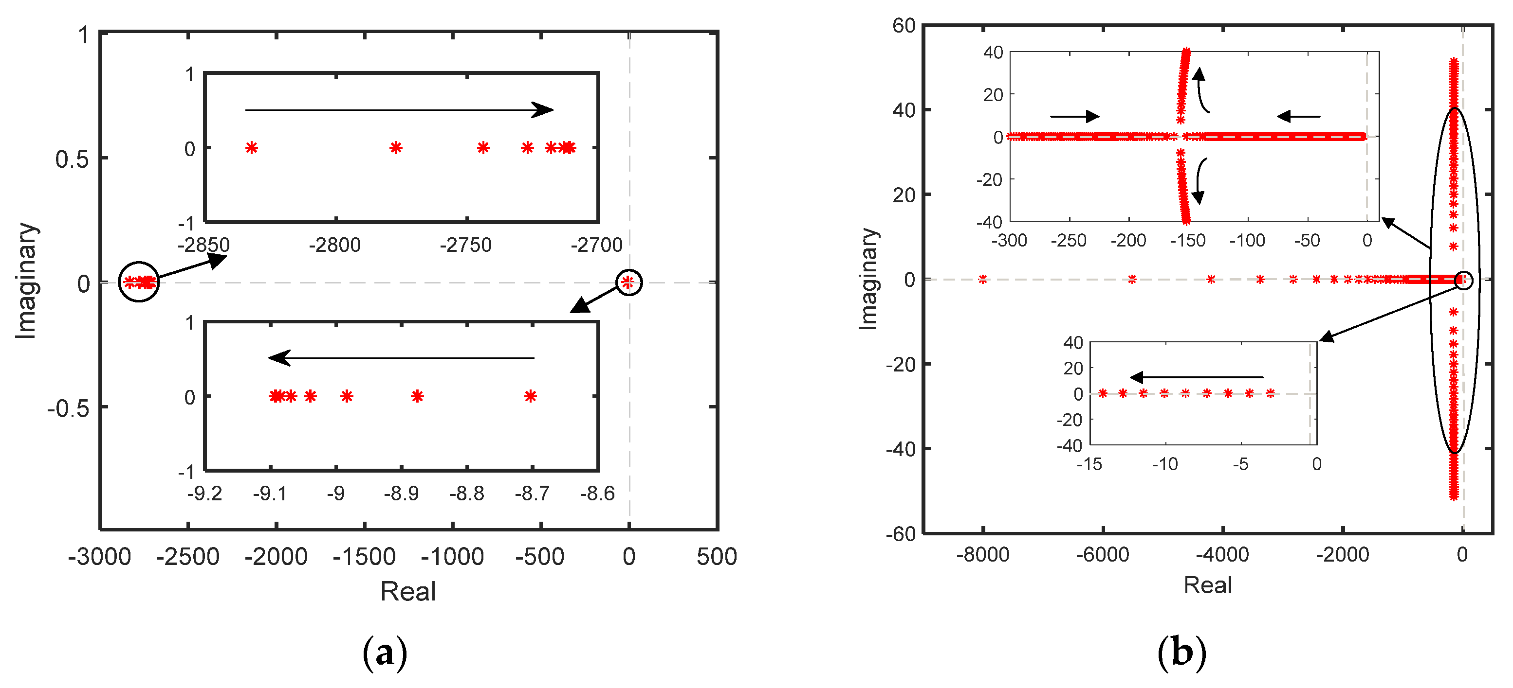
The stability of the system with PEFDC can be analyzed through the characteristic equation. ESU 1 and ESU 2 have the same rated voltage and the same capacity as 500 V and 20 Ah, respectively. The initial droop factor is 0.000001. The cut-off frequency and damping factor of the low-pass filter are 157 rad/s and 0.707, respectively. Figure 7a shows the change of eigenvalues when m = 3, n = 5, p = 5, = 0.9 and changes from 0.8 to 0.1 with an interval of 0.1. As SoC decreases, the main eigenvalue moves to the left away from the imaginary axis on the real axis and all eigenvalues are on the left half-plane, so the system is stable. The relationship between and is equivalent and will not be analyzed further. Figure 7b shows the change of eigenvalues when m = 3, n = 5, = 0.9, = 0.8 and p varies from 1 to 200 with an interval of 1. It can be observed that the eigenvalues are always on the left half-plane as p increases. When p is 163, the system starts to appear with a pair of conjugate complex eigenvalues (−156.8 ± 7.715j) at which the system will start to oscillate, so it is not appropriate to take a value of p greater than 163. As m = 3, p = 5, = 0.9 and SoC2 = 0.8, the change of eigenvalues when n varies from 30 to 1 with an interval of 1 is analyzed, which is shown in Figure 7c. As n decreases, the dominant eigenvalues move away from the imaginary axis, so the rapidity of the system is enhanced. Because all the eigenvalues are on the real axis on the left half-plane, the system is smooth and free of overshoot. In Figure 7d, as n = 5, p = 5, = 0.9 and SoC2 = 0.8, the system is stable as all eigenvalues are on the negative half-axis of the real axis as the factor m increases from 1 to 30.
4.2. System Frequency Deviation
In this paper, the sharing of power on the distributed energy storage side is analyzed and the conventional virtual impedance droop control method is used to solve the reactive power sharing problem. In islanded operation, the AC microgrid supported by the ESUs will incur frequency deviations, as can be seen from Equation (3), which is rewritten as
As can be seen from Equation (31), the frequency deviation of the AC microgrid in islanded operation is related to the initial droop coefficient and the factors m, n and p. Therefore, in order to ensure that the system frequency deviation is within a reasonable range, an appropriate value for the initial droop coefficient and the factors m, n and p need to be specified. It can be seen from Equation (3) that the droop coefficient of the converter satisfies the following relation:
In order to ensure stable operation of the system within a reasonable frequency range, we need to ensure that the product of the maximum value of the droop coefficient and the difference between the output power and the rated power is less than the maximum allowed deviation of the AC microgrid system frequency, i.e., satisfying Equation (33).
5. Simulation and Hardware-in-the-Loop Experiment
5.1. Simulation Parameters
To verify the effectiveness of the proposed improved droop control strategy, a parallel model of two energy storage batteries was built in the MATLAB/Simulink environment to simulate the islanded operation of a multi-storage AC microgrid. The converter carrier frequency is 6000 Hz, the output frequency of the converters is 50 Hz and the simulation step of the system is 30 μs. Other simulation parameters are shown in Table 1.
5.2. Sharing of Load Power
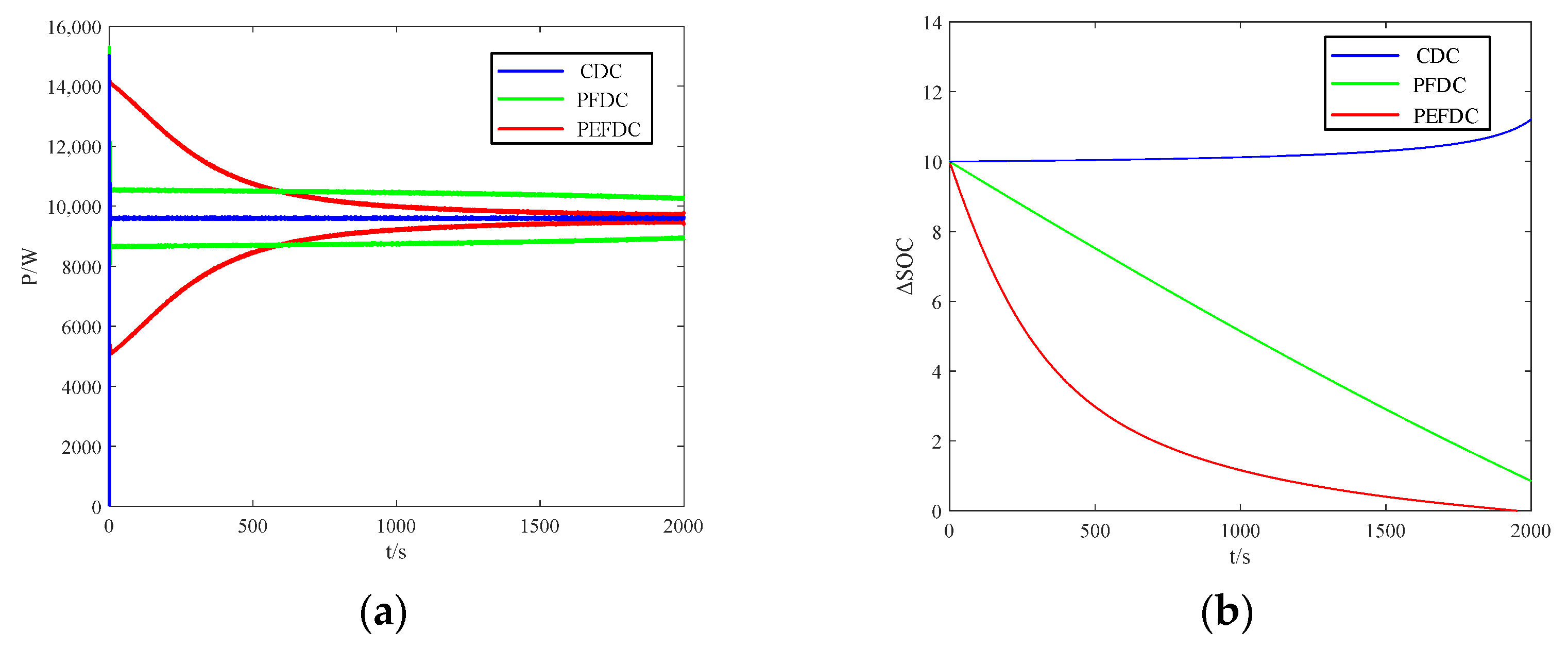
As shown in Table 1, all the parameters in the system are the same, the difference is the state of charge of the energy storage battery, and if required, take n = 5, p = 7 and m = 3. Three methods will be compared: the conventional droop control (CDC), the power function droop control (PFDC) and the power exponential function droop control (PEFDC). Figure 8a shows the comparison of the active power output of the ESU (ESU) where the blue, green and red lines represent the active power output of the ESUs with the application of CDC, PFDC and PEFDC, respectively. As can be seen from the figure, the CDC strategy allows the active power to be shared evenly, but cannot adjust the output active power according to the actual remaining power of the ESU. The green lines (PFDC) and red lines (PEFDC) show that ESUs can output active power according to their SoC, and the red lines represent the better control performance. Figure 8b shows the SoC difference between the two ESUs. The SoC difference between ESUs cannot be equalized and even increases when applying CDC. The PFDC can reduce the difference of SoC, but the SoC equalization process is slow. Finally, the PEFDC strategy achieves fast SoC equalization and the approaches 0 when t = 2000 s.
5.3. Comparisons
Table 2 compares the three droop control methods applied to the AC microgrid. It can be seen that the proposed power exponential droop control method has superiority over the other methods. The control method can be used in AC microgrids with multiple energy storages.
5.4. Role and Design of Factors m, n and p
From Section 4.1, it is known that the system is stable over the range of , and during the variation of SoC. To further narrow the range of values taken, the following should be done. Given by (3), a droop coefficient function Z(SoC) is defined as
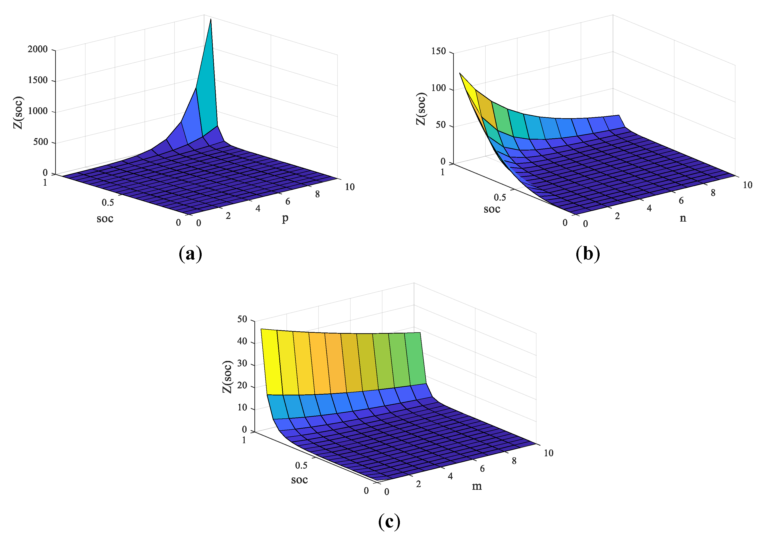
The effect of the parameters m, n, p and SoC on Z(SoC) is shown in Figure 9. Figure 9a is a surface plot of the droop coefficient for m = 3, n = 5, and . It can be seen from the plot that when SoC varies and p is in the range of [0,9], the variation of Z(SoC) is smoother, which is beneficial to the design of the parameters, so p can be taken in the range of [0,9]. Figure 9b is a surface plot of Z(SoC) for m = 3, p = 5, and . As can be seen from the graph, the surface plot is relatively smooth, so n can be taken in the range of [1, 10]. Similarly, Figure 9c is a surface plot of Z(SoC) for n = 5, p = 5, and ; the surface is smooth, as m varies and is suitable for the design of the parameters.
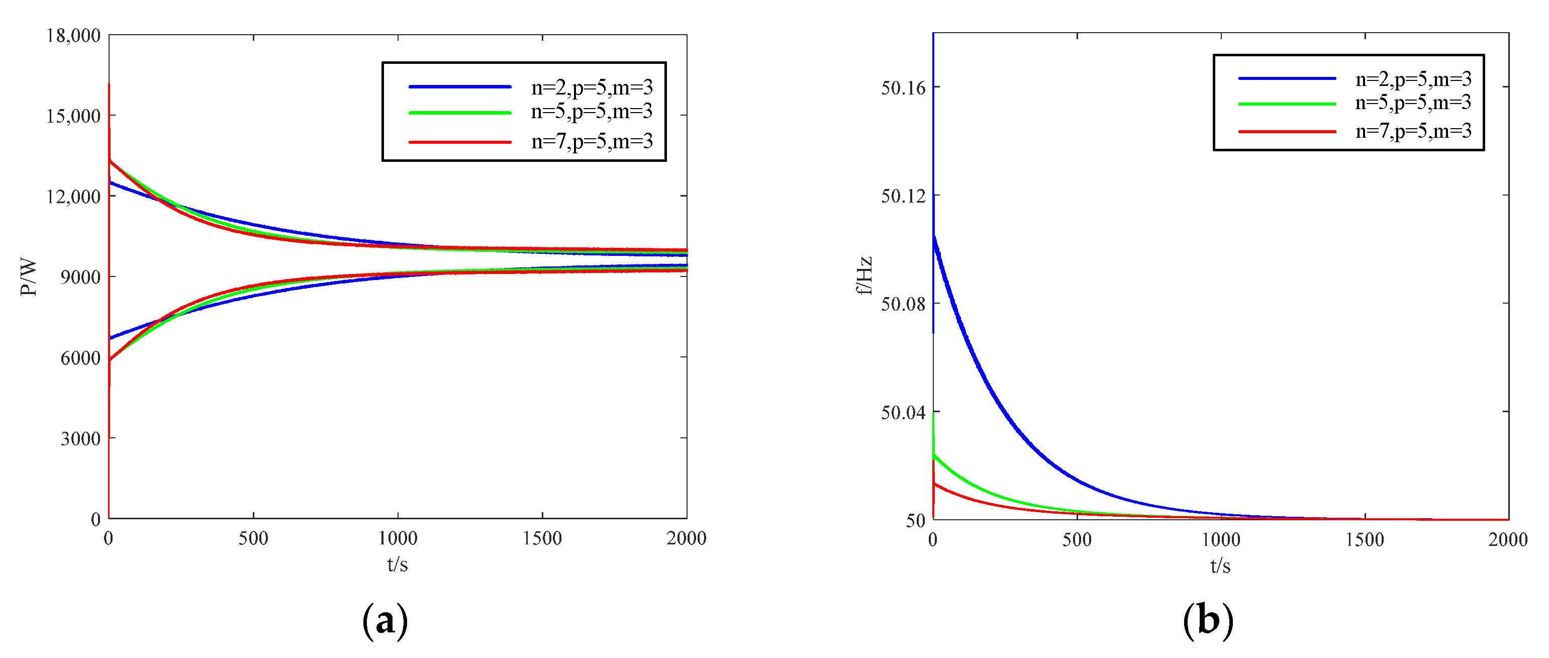
Figure 10 shows the variation of the ESU output power and the fluctuation of system frequency when the factor n is taken to different values, while m = 3 and p = 5. It can be seen from Figure 10a,b that the factor n has little influence on the power output from the ESUs, but mainly affects the frequency of the system. The larger n is, the smaller the frequency fluctuation of the system. Therefore, the system frequency can be stabilized by adjusting the value of n.
Figure 11 illustrates the output power of ESU and the system frequency fluctuations when the factor p is taken differently, while m = 3 and n = 5. As can be seen from Figure 11a,b, an increase in p mainly affects the output power of the ESUs. The larger p is, the more significant the distinction between the output powers of the ESUs. Therefore, the system frequency can be stabilized and good control performance is achieved by selecting a reasonable combination of factors n and p. The ESU with high SoC outputs a large power while the other outputs a small power, and they converge gradually.
5.5. Hardware-in-the-Loop Experiment
To verify the validity of the proposed control strategy, the hardware-in-the-loop experiment is conducted to verify the validity of the algorithm. The experimental environment is shown in the Figure 12. Two main aspects are considered: (a) the correctness of the strategy; (b) the effectiveness of the strategy in the event of sudden changes in load. The experimental parameters are shown in Table 3.
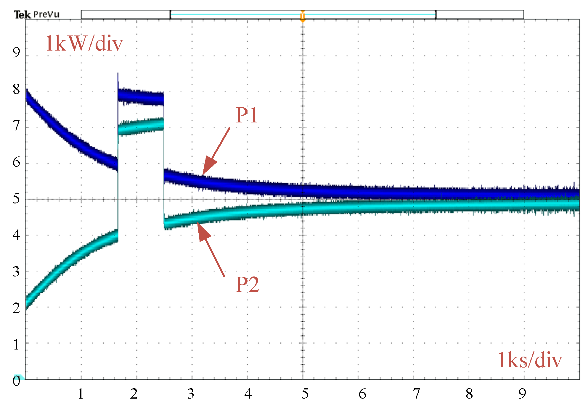
At 1600 s, the active load is increased by 5 kW and the active powers from the ESUs are shown in Figure 13. It can be seen that the ESU with a higher charge state outputs more power, while the other outputs less power, and they tend to be the same as the SoC approaches. When the load increases suddenly, the strategy still works.
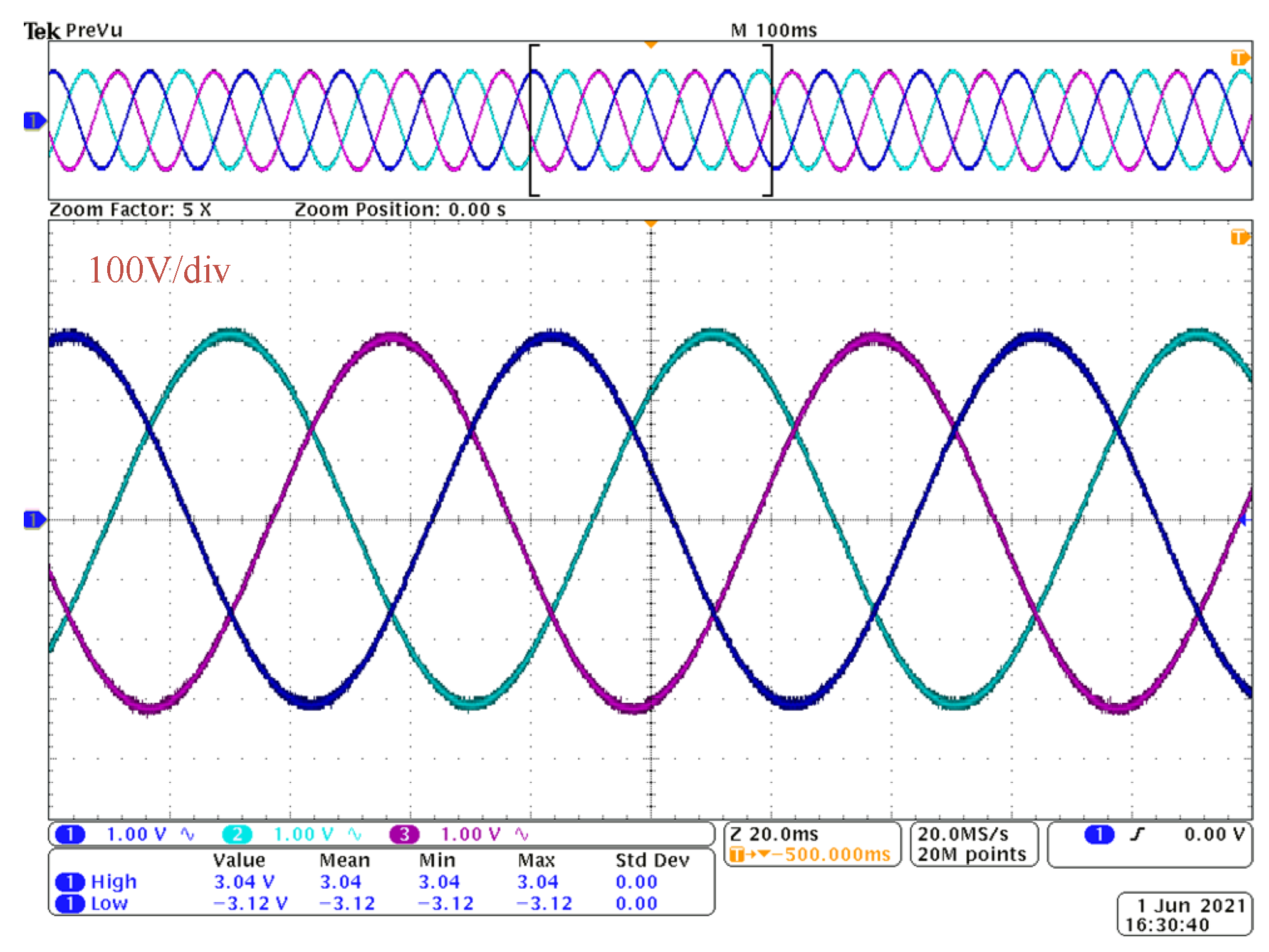
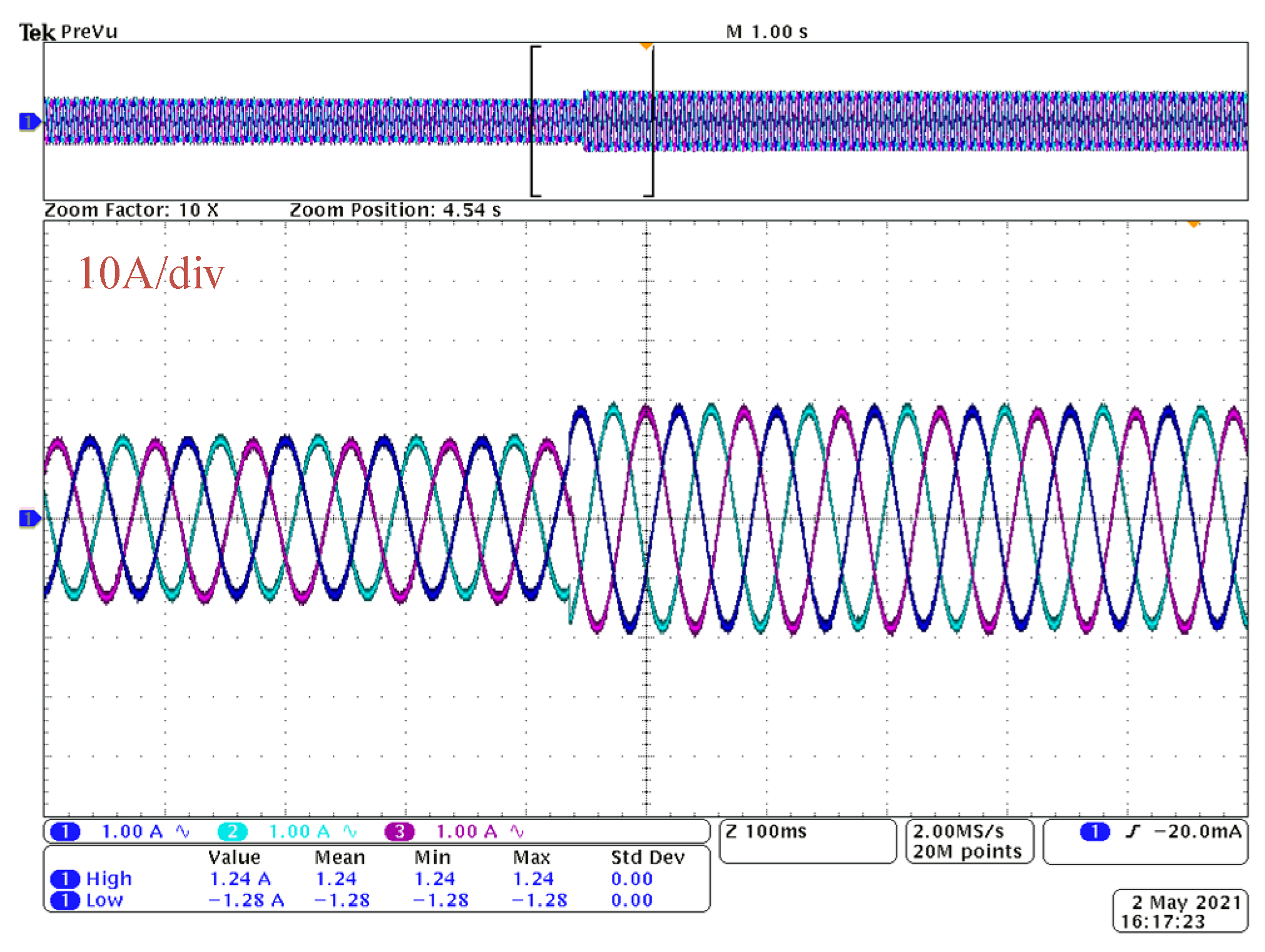
Figure 14 shows the waveforms of the bus voltage before and after the increase in load. It is obvious that the voltages are stable. Figure 15 shows the current variation of the converter, from which it can be seen that the converter currents increase rapidly when the load increases and reach stability quickly.
6. Conclusions
In this paper, an improved droop control strategy of an AC microgrid with multi-energy storage is proposed, and a power exponential function between the droop coefficient and SoC is constructed. Then, the small signal perturbation method is used to analyze the stability of the system. In addition, conventional droop and power function droop methods are also built for comparison. The role of the factors m, n and p and their effects on system stability are also analyzed. Finally, the simulation and HIL experiment are conducted. The results lead to the following conclusions.
(1) In an AC microgrid operating in islanded mode, the proposed control strategy allows the ESU to adjust its output adaptively based on its own SoC. The ESU with high SoC outputs a high power, and the one with low SoC outputs a low power. They output the same power at the same SoC.
(2) Small-signal analysis is used to analyze the stability of the system and to determine the ranges of factors m, n and p. The system frequency can be stabilized and the SoCs can be equalized quickly by adjusting the factors.
(3) The proposed control strategy does not require communication between ESUs. Compared to CDC and PFDC, the PEFDC has a faster SoC equalization rate and remains effective when the ESUs have small SoCs.
(4) The AC microgrid model with multiple EMUs is tested through the hardware-in-the-loop experiment, and the results verify the effectiveness of the proposed power exponential function droop control strategy.
Author Contributions
Data curation, H.W.; Investigation, X.W. and H.W.; Writing—original draft, H.W.; Writing—review and editing, X.W. All authors have read and agreed to the published version of the manuscript.
Funding
This work was supported by the “Guangzhou Science and Technology Plan Project, no. 202102010404”, and the “Guangdong Provincial Science and Technology Planning Project of China”, no. 2015A010106015.
Conflicts of Interest
The authors declare no conflict of interest.
References
- Han, H.; Hou, X.C.; Yang, J.; Wu, J.F.; Su, M.; Guerrero, J.M. Review of power sharing control strategies for islanding operation of ac microgrids. IEEE Trans. Smart Grid 2016, 7, 200–215. [Google Scholar] [CrossRef] [Green Version]
- Blaabjerg, F.; Teodorescu, R.; Liserre, M.; Timbus, A.V. Overview of control and grid synchronization for distributed power generation systems. IEEE Trans. Ind. Electron. 2006, 53, 1398–1409. [Google Scholar] [CrossRef] [Green Version]
- Olivares, D.E.; Mehrizi-Sani, A.; Etemadi, A.H.; Cañizares, C.A.; Iravani, R.; Kazerani, M.; Hajimiragha, A.H.; Gomis-Bellmunt, O.; Saeedifard, M.; Palma-Behnke, R.; et al. Trends in microgrid control. IEEE Trans. Smart Grid 2014, 5, 1905–1919. [Google Scholar] [CrossRef]
- Justo, J.J.; Mwasilu, F.; Ju, L.; Jung, J.W. AC-microgrids versus DC-microgrids with distributed energy resources: A review. Renew. Sustain. Energy Rev. 2013, 24, 387–405. [Google Scholar] [CrossRef]
- Huang, J.Y.; Jiang, C.W.; Xu, R. A review on distributed energy resources and microgrid. Renew. Sustain. Energy Rev. 2008, 12, 2472–2483. [Google Scholar]
- Kahrobaeian, A.; Mohamed, Y.A.I. Analysis and mitigation of low-frequency instabilities in autonomous medium-voltage converter-based microgrids with dynamic loads. IEEE Trans. Ind. Electron. 2014, 61, 1643–1658. [Google Scholar] [CrossRef]
- Li, Z.M.; Xu, Y. Temporally-coordinated optimal operation of a multi-energy microgrid under diverse uncertainties. Appl. Energy 2019, 240, 719–729. [Google Scholar] [CrossRef]
- Guo, F.H.; Wen, C.Y.; Mao, J.F.; Song, Y.D. Distributed secondary voltage and frequency restoration control of droop-controlled inverter-based microgrids. IEEE Trans. Ind. Electron. 2015, 62, 4355–4364. [Google Scholar] [CrossRef]
- Green, T.C.; Prodanovic, M. Control of inverter-based micro-grids. Electr. Power Syst. Res. 2007, 77, 1204–1213. [Google Scholar] [CrossRef] [Green Version]
- Rocabert, J.; Luna, A.; Blaabjerg, F.; Rodriguez, P. Control of power converters in ac microgrids. IEEE Trans. Power Electron. 2012, 27, 4734–4749. [Google Scholar] [CrossRef]
- Wu, T.F.; Chen, Y.K.; Huang, Y.H. 3C strategy for inverters in parallel operation achieving an equal current distribution. IEEE Trans. Ind. Electron. 2000, 47, 273–281. [Google Scholar]
- Katiraei, F.; Iravani, M.R. Power management strategies for a microgrid with multiple distributed generation units. IEEE Trans. Power Syst. 2006, 21, 1821–1831. [Google Scholar] [CrossRef]
- Niu, H.C.; Jiang, M.; Zhang, D.M.; Fletcher, J. Autonomous Micro-grid operation by employing weak droop control and PQ control. In Proceedings of the 2014 Australasian Universities Power Engineering Conference, New York, NY, USA, 28 September–1 October 2014; pp. 1–5. [Google Scholar]
- Zhang, X.M.; Sun, W.F.; Xu, S.; Wang, C. High precision constant voltage digital control scheme for primary-side controlled flyback converter. IET Power Electron. 2016, 9, 2522–2533. [Google Scholar]
- Yao, W.; Chen, M.; Alcala, J.M.; Guerrero, J.M.; Qian, Z.M. Design and analysis of the droop control method for parallel inverters considering the impact of the complex impedance on the power sharing. IEEE Trans. Ind. Electron. 2011, 58, 576–588. [Google Scholar] [CrossRef]
- Liu, J.; Miura, Y.; Ise, T. Comparison of Dynamic characteristics between virtual synchronous generator and droop control in inverter-based distributed generators. IEEE Trans. Power Electron. 2016, 31, 3600–3611. [Google Scholar] [CrossRef]
- Guerrero, J.M.; Vasquez, J.C.; Alcala, J.M.; Vicuna, L.G. Hierarchical control of droop-controlled ac and dc microgrids—A general approach toward standardization. IEEE Trans. Ind. Electron. 2011, 58, 158–172. [Google Scholar] [CrossRef]
- Vasquez, J.C.; Guerrero, J.M.; Savaghebi, M.; Carrasco, E.G.; Teodorescu, R. Modeling, analysis, and design of stationary-reference-frame droop-controlled parallel three-phase voltage source inverters. IEEE Trans. Ind. Electron. 2013, 60, 1271–1280. [Google Scholar] [CrossRef] [Green Version]
- Zhang, G.R.; Ding, X.T.; Peng, B.; Xie, R.S.; Bi, K.J. Improved control strategy for an ac/dc hybrid microgrid interlinking converter. Power Syst. Prot. Control 2020, 48, 50–58. [Google Scholar]
- Li, J.J.; Wu, Z.J.; Yang, S.H.; Lv, Z.Y.; Liu, H.J.; Shen, Y. Power control and mode switching method of power electronic transformer in ac/dc hybrid microgrid. Electr. Power Autom. Equip. 2020, 40, 82–87. [Google Scholar]
- Lu, X.N.; Sun, K.; Guerrero, J.M.; Vasquez, J.C.; Huang, L.P.; Teodorescu, R. SoC-based droop method for distributed energy storage in DC microgrid applications. In Proceedings of the 2012 IEEE International Symposium on Industrial Electronics, Hangzhou, China, 28–31 May 2012; pp. 1640–1645. [Google Scholar]
- Wu, Q.F.; Guan, R.Z.; Sun, X.F.; Wang, Y.N.; Li, X. SoC balancing strategy for multiple energy storage units with different capacities in islanded microgrids based on droop control. IEEE J. Emerg. Sel. Top. Power Electron. 2018, 6, 1932–1941. [Google Scholar] [CrossRef]
- Lu, X.N.; Sun, K.; Guerrero, J.M.; Vasquez, J.C.; Huang, L.P. Double-quadrant state-of-charge-based droop control method for distributed energy storage systems in autonomous dc microgrids. IEEE Trans. Smart Grid 2015, 6, 147–157. [Google Scholar] [CrossRef] [Green Version]
- Palizban, O.; Kauhaniemi, K. Power sharing for distributed energy storage systems in AC microgrid: Based on state-of-charge. In Proceedings of the 2015 IEEE PES Asia-Pacific Power and Energy Engineering Conference, Brisbane, Australia, 15–18 November 2015; pp. 1–5. [Google Scholar]
- Lu, X.N.; Sun, K.; Huang, L.P.; Xiao, X.; Guerrero, J.M. An improved droop control method for distributed energy storage system in an isolated AC microgrid. Autom. Electr. Power Syst. 2013, 37, 180–185. [Google Scholar]
- Li, Y.R.; Vilathgamuwa, D.M.; Loh, P.C. Design, analysis, and real-time testing of a controller for multibus microgrid system. IEEE Trans. Power Electron. 2004, 19, 1195–1204. [Google Scholar] [CrossRef]
- Shravan, V.S.; Vyjayanthi, C. Active power filtering using interlinking converter in droop controlled islanded hybrid AC-DC microgrid. Int Trans. Electr. Energy Syst. 2020, 30, e12333. [Google Scholar] [CrossRef]
- Ng, K.S.; Moo, C.S.; Chen, Y.P.; Hsieh, Y.C. Enhanced coulomb counting method for estimating state-of-charge and state-of-health of lithium-ion batteries. Appl. Energy 2009, 86, 1506–1511. [Google Scholar] [CrossRef]
Figure 1.
A typical topology of an AC microgrid.

Figure 2.
Droop characteristic curves of Q-V and P-f.

Figure 3.
The mathematical simulation results.

Figure 4.
Structure of the battery-dominated hybrid microgrid under islanded operation.

Figure 5.
Schematic diagram of the reference voltage generation.

Figure 6.
Structure of the voltage and current double closed-loop control.

Figure 7.
Distribution of eigenvalues: (a) changes with SoC; (b) changes with p; (c) changes with n; (d) changes with m.
Figure 7.
Distribution of eigenvalues: (a) changes with SoC; (b) changes with p; (c) changes with n; (d) changes with m.


Figure 8.
Comparisons of the three methods: (a) active power outputs; (b) SoC differences.

Figure 9.
The effect of the parameters m, n, p and SoC on the droop coefficient: (a) m = 3, n = 5, SoC = 0.1~0.95, p = 0~10, surf of Z(SoC); (b) m = 3, p = 5, SoC = 0.1~0.95, n = 0~10, surf of Z(SoC); (c) n = 5, p = 5, SoC = 0.1~0.95, m = 0~10, surf of Z(SoC).
Figure 9.
The effect of the parameters m, n, p and SoC on the droop coefficient: (a) m = 3, n = 5, SoC = 0.1~0.95, p = 0~10, surf of Z(SoC); (b) m = 3, p = 5, SoC = 0.1~0.95, n = 0~10, surf of Z(SoC); (c) n = 5, p = 5, SoC = 0.1~0.95, m = 0~10, surf of Z(SoC).

Figure 10.
Influence of factors n on active powers and system frequency as m = 3 and p = 5: (a) influence of factor n on power allocation; (b) influence of factor n on frequency fluctuations.
Figure 10.
Influence of factors n on active powers and system frequency as m = 3 and p = 5: (a) influence of factor n on power allocation; (b) influence of factor n on frequency fluctuations.

Figure 11.
Influence of factors p on active power and system frequency as m = 3 and n = 5: (a) influence of factor p on power allocation; (b) influence of factor n on frequency fluctuations.
Figure 11.
Influence of factors p on active power and system frequency as m = 3 and n = 5: (a) influence of factor p on power allocation; (b) influence of factor n on frequency fluctuations.

Figure 12.
Experimental environment.

Figure 13.
Active powers from ESUs.

Figure 14.
The voltage variation of the bus.

Figure 15.
The current variation of the converter.


Table 1.
Simulation parameters.
| Parameter | Value | Parameter | Value |
|---|---|---|---|
| vbat1 and vbat2 | 500 V | vref | 310 V |
| Ce1 and Ce2 | 30 Ah | Rf | 0.1 Ω |
| SoC10 | 0.9 | Lf | 3 mH |
| SoC20 | 0.8 | Cf | 1.5 mF |
| kp | 1 × 10⁻⁵ | Rc | 0.01 Ω |
| kq | 3 × 10⁻⁵ | Lc | 3 mH |
| Pload | 20 kW | C1 | 3 mF |
Table 2.
Comparisons of droop control methods.
| Method | Reasonable Power Sharing | SoC Equalization Rate | System Frequency | Communication | Stability Analysis |
|---|---|---|---|---|---|
| CDC | ignore | ignored | ignored | not required | ignored |
| PFDC | not accurate | defective | defective | not required | not ignored |
| PEFDC | accurate | adjustable | not ignored | not required | not ignored |
Table 3.
Experimental parameters.
| Parameter | Value | Parameter | Value |
|---|---|---|---|
| vbat1 and vbat2 | 500 V | Rf | 0.1 Ω |
| Ce1 and Ce2 | 20 Ah | Lf | 5 mH |
| SoC10 | 0.85 | Cf | 1.5 mF |
| SoC20 | 0.78 | Rc | 0.01 Ω |
| kp | 1 × 10⁻⁵ | m | 3 |
| kq | 3 × 10⁻⁵ | n | 5 |
| Pload | 10 kW | p | 7 |
Publisher’s Note: MDPI stays neutral with regard to jurisdictional claims in published maps and institutional affiliations. |
© 2021 by the authors. Licensee MDPI, Basel, Switzerland. This article is an open access article distributed under the terms and conditions of the Creative Commons Attribution (CC BY) license (https://creativecommons.org/licenses/by/4.0/).
Share and Cite
MDPI and ACS Style
Wang, X.; Wang, H. Improved Droop Control Strategy of Multiple Energy Storage Applications in an AC Microgrid Based on the State of Charge. Electronics 2021, 10, 1726. https://0-doi-org.brum.beds.ac.uk/10.3390/electronics10141726
AMA Style
Wang X, Wang H. Improved Droop Control Strategy of Multiple Energy Storage Applications in an AC Microgrid Based on the State of Charge. Electronics. 2021; 10(14):1726. https://0-doi-org.brum.beds.ac.uk/10.3390/electronics10141726
Chicago/Turabian StyleWang, Xiaogang, and Hongdong Wang. 2021. "Improved Droop Control Strategy of Multiple Energy Storage Applications in an AC Microgrid Based on the State of Charge" Electronics 10, no. 14: 1726. https://0-doi-org.brum.beds.ac.uk/10.3390/electronics10141726
Note that from the first issue of 2016, this journal uses article numbers instead of page numbers. See further details here.