
Bloom Filter-Based Parallel Architecture for Accelerating Equi-Join Operation on FPGA


1
College of Biomedical Engineering & Instrument Science, Zhejiang University, Hangzhou 310027, China
2
College of Cyberspace Security, Hangzhou Dianzi Univerisity, Hangzhou 310027, China
3
Department of Biomedical Engineering, The Chinese University of Hong Kong, Hong Kong 999077, China
*
Author to whom correspondence should be addressed.
†
Wei Luo is now a research associate in the Chinese University of Hong Kong. He finished all the work in this paper when he was in Zhejiang University.
Electronics 2021, 10(15), 1778; https://0-doi-org.brum.beds.ac.uk/10.3390/electronics10151778
Submission received: 6 July 2021
/
Revised: 21 July 2021
/
Accepted: 23 July 2021
/
Published: 25 July 2021
(This article belongs to the Section Circuit and Signal Processing)
Abstract
:As one of the most important operations in relational databases, the join is data-intensive and time-consuming. Thus, offloading this operation using field-programmable gate arrays (FPGAs) has attracted much interest and has been broadly researched in recent years. However, the available SRAM-based join architectures are often resource-intensive, power-consuming, or low-throughput. Besides, a lower match rate does not lead to a shorter operation time. To address these issues, a Bloom filter (BF)-based parallel join architecture is presented in this paper. This architecture first leverages the BF to discard the tuples that are not in the join result and classifies the remaining tuples into different channels. Second, a binary search tree is used to reduce the number of comparisons. The proposed method was implemented on a Xilinx FPGA, and the experimental results show that under a match rate of 50%, our architecture achieved a high join throughput of 145.8 million tuples per second and a maximum acceleration factor of 2.3 compared to the existing SRAM-based join architectures.
1. Introduction
The performance of the central processing unit (CPU) is not growing sufficiently quickly to handle the rapidly increasing amount of data, leading to demands for new processing methods to speed up database systems. The field-programmable gate array (FPGA) is a good choice to migrate the computational pressure of CPUs by offloading certain data-intensive and time-consuming operations in databases [1,2,3,4]. In relational databases, the join operator is intensively used to combine tuples from two or more relations given a common key, which requires a significant amount of computing resources. Therefore, accelerating this operation with FPGAs has received a great deal of attention.
The sort–merge join and hash-join are the two main join algorithms used in hardware acceleration. The sort–merge join [5,6,7] sorts tuples of each table according to a key first and completes the join operation by scanning each table only once. The research focus in accelerating the sort–merge join is usually dedicated to the sorting phase; for example, Chen [6] designed a parallel and pipelined bitonic sorter on the FPGA, and Casper [5] presented a dedicated hardware solution to perform a merge sort entirely in hardware. Both works achieve high data throughput, benefiting from complicated sorting structures, while Zhou et al. [7] attempted to accelerate the merge phase. They used hierarchical indexes to identify result-yielding regions and acquired good performance with low match rates. The hash-join algorithm [8,9,10] utilizes extra memory (hash table) to avoid scanning the entire first table while scanning the second table. The major issue of this algorithm is hash collisions. Werner [8] implemented two different hash-join accelerators by reprocessing the collision tuple; Halstead [9] redistributed the same table by different hash functions, thus duplicating the table, meaning that the memory usage was large. Xue [10] used the cuckoo hash algorithm to distribute the first table and achieved a high join throughput. However, the performance of this algorithm drops dramatically when the slots are full and chain lists are employed.
The join architectures mentioned above have certain advantages and are suitable for different application scenarios. However, they are either resource-intensive or low-throughput. Zhang [11] proposed a tree-based join architecture that balances the hardware resource utilization and throughput. In their method, the first table is arranged into a binary search tree in the build phase and compared to the second table in the probe phase. This design avoids a complicated sort structure and searches the whole table by simply partitioning the first table by different channels. Nevertheless, its performance is not satisfying as it requires a large number of process cycles for each tuple on average. Furthermore, the operation time cannot be reduced as the match rate decreases because the whole second table is always traversed.
Based on Zhang’s work [11], we present a Bloom filter-based parallel join architecture. In this study, we explore two important issues, namely the filter efficiency to avoid unnecessary search operations and the search efficiency of the binary search tree to improve the join performance. The proposed architecture first uses a Bloom filter to discard the tuples that do not meet the join condition to reduce the number of searches; subsequently, the tuples are classified into different channels to shorten the depth of the binary search tree. With the potential tuples that may satisfy the join condition, a binary search tree algorithm is used to shorten the search path. In this way, both the filter efficiency and search efficiency of the binary search tree are improved. Similar to Zhou’s work [7], this design aims to accelerate the join operation in the probe phase when the match rate is low. In general terms, the main contributions of this paper are as follows:
- A Bloom filter-based join strategy is proposed. Compared to Zhang’s work [11], the proposed strategy reduces the number of search operations, thus improving the join performance;
- A parallel join architecture composed of a Bloom filter and multiple binary trees is constructed. Compared to a sort-based join architecture, it avoids the complicated sort structure; compared to a hash join architecture, it improves the join performance with a chain list; compared with Zhang’s work [11], it reduces the average number of cycles to process a tuple;
- The theoretical analysis of the Bloom filter design is given and the performance improvement by adding this Bloom filter is experimentally illustrated.
2. Preliminaries
2.1. Equi-Join
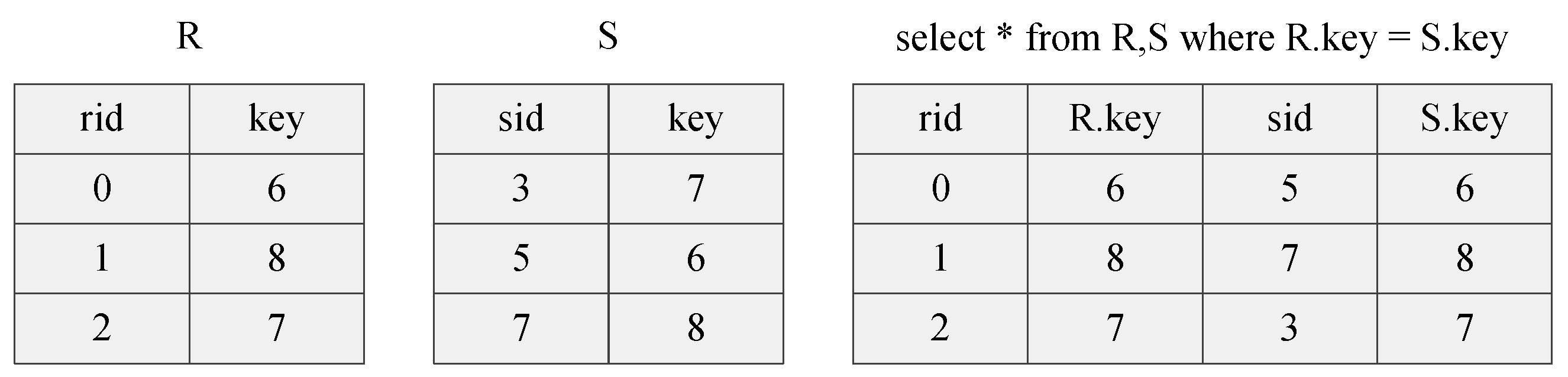
The equi-join is a specific type of join used to combine two tables using equality comparison on specified fields. Figure 1 shows an example of an equi-join on table R and table S using the join attribute (each table’s key field). Each record in R is combined with records in S if they have the same key to form new records in the result table.
2.2. Bloom Filter
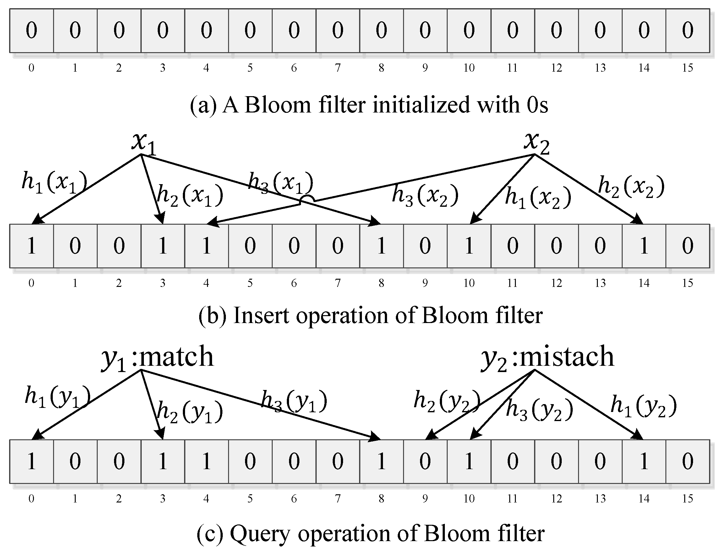
A Bloom filter (BF) [12] is a space-efficient data structure for testing whether an element is a member of a set. It is a bit array containing m bits that can be accessed by their address, combined with k different hash functions; for example, ,,⋯,. A BF includes three operations: reset, insert and query. During the reset operation, each bit in the BF is set to 0, making the BF an empty filter. During insert operation, an element is inserted into the set by hashing this element k times using k hash functions and setting the k bits in the memory at the index of those hashes to 1. The query operation is similar to the insert operation. It hashes the query element k times and reads the corresponding k bits from the memory instead of writing to it. If all the bits are 1, it reports that the element is possibly in the set; otherwise, it reports that the element is not in the set. Figure 2 illustrates the three operations of the BF with 3 different hash functions and a memory of 16 bits.
3. Proposed Join Architecture
To accelerate the join operation on FPGA, we propose a Bloom filter-based join architecture. In our architecture, we suppose two tables stream into the FPGA row by row. In the following discussion, we use and to denote the first table and the second table, respectively. Each tuple in the format of {id, key} streams into the FPGA is part of the integrated records. The id field is used to identify a distinct row in the table and the key field is the join attribute. The output tuples in the format of {ida, idb, key} are generated when streams in.
This architecture operates in two phases: a build phase and a probe phase. In the build phase, tuples of stream in and are recorded by the BF. Then, they are stored into the tree tables to form binary search trees. In the probe phase, streams in and is filtered by the BF. For every tuple of the remaining table, the binary search trees are searched to produce join results.
3.1. Binary Search Tree Model
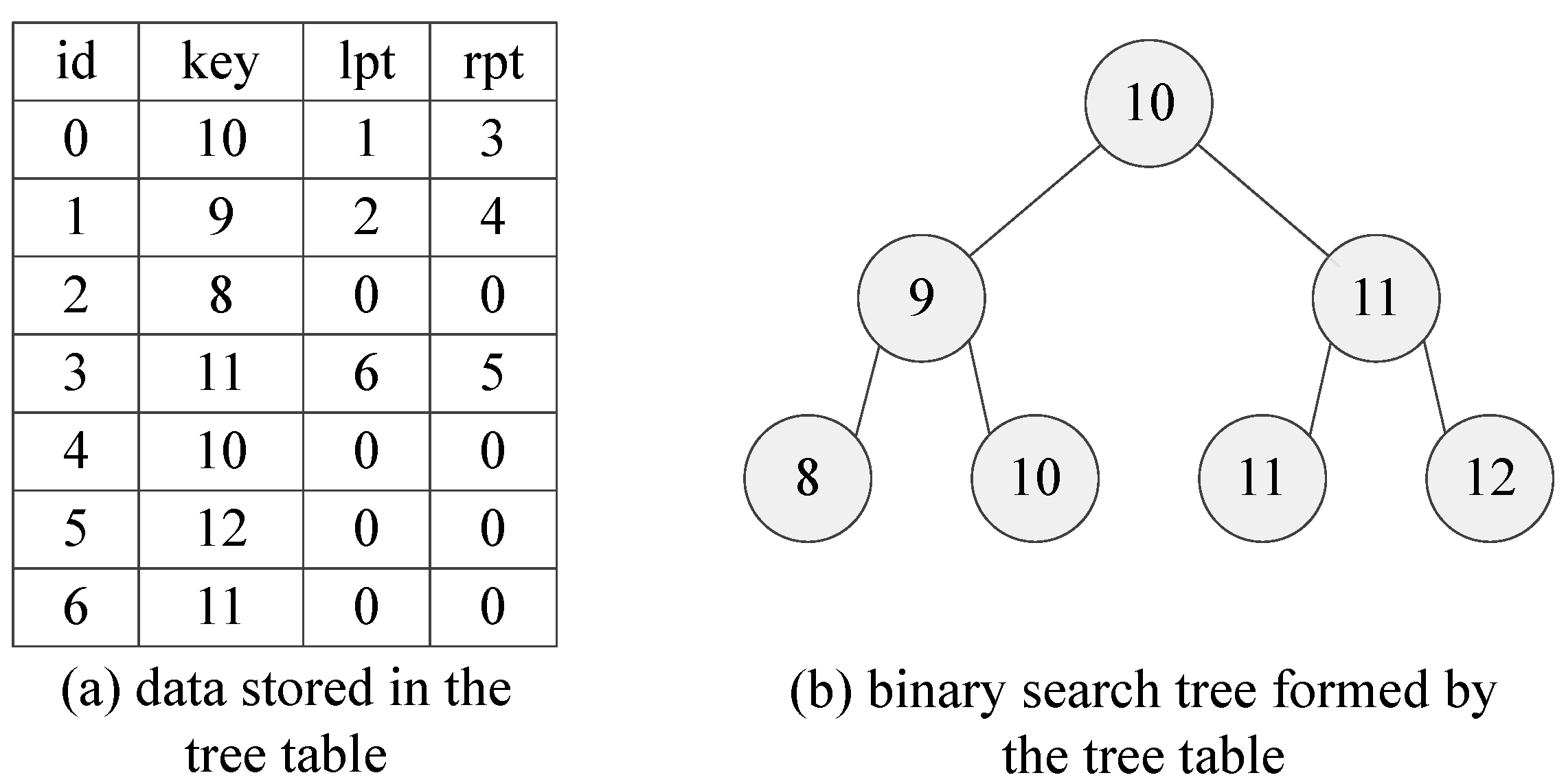
In our architecture, is formed into a binary search tree. In the binary search tree, each node has four attributes, namely id, key, lpt and rpt. The id and key fields are obtained from the tuple of . The terms lpt and rpt are the addresses pointing to the left child node and right child node. We assume that the key fields of the input sequence are 10, 9, 8, 11, 10, 12 and 11 with the id numbers increasing from 0 to 6. Figure 3 depicts how the data are stored in the tree table and how the data are formed into a binary search tree.
3.2. Overall Architecture
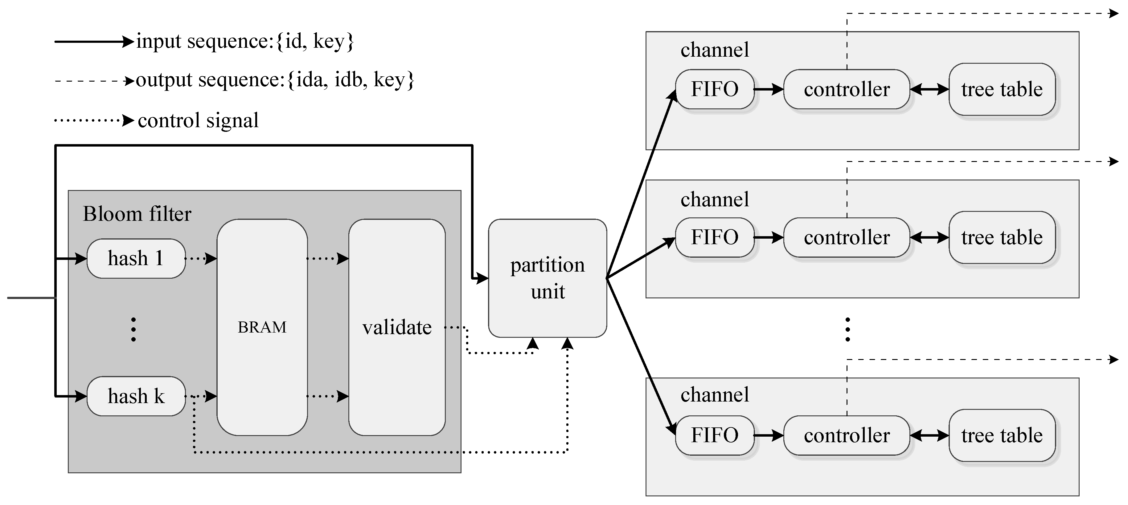
The overall join architecture depicted in Figure 4 consists of the following modules:
- (1)
- A BF used to filter to reduce unnecessary searches.
The BF module consists of k hash modules, one block RAM(BRAM) and a validation module. During the build phase, it performs insert operations. The key field of each tuple is hashed by k hash modules as the addresses of BRAM, and the corresponding k bits in BRAM are set to 1. The validation module’s output is always high during the build phase as we do not need to filter . During the probe phase, the BF module performs query operations. In the same manner as the build phase, the key field of each tuple is hashed k times. Then, the validation module reads the corresponding k bits in BRAM and asserts its output to be high only when all the k bits are 1. Tuples of will be filtered by the partition module if the validate module’s output is 0.
- (2)
- Multiple backend processing channels to store in the format of the binary search tree, to search the binary tree and output join results.
The backend channel consists of a FIFO, a controller and a tree table. During the build phase, the controller reads tuples from the FIFO and inserts tuples into the tree table in the format as shown in Figure 3. During the probe phase, it reads tuples from the FIFO and searches the tree table to find a match. This module needs more than one clock cycle to process one tuple, and a small FIFO using distributed RAM to cache the incoming tuples is adopted. To fit the tree table size with , we use a dual-port BRAM to implement the tree table, under the consideration of the performance issue.
- (3)
- A partition unit responsible for balancing the workload of backend channels.
Since the BF module is fully pipelined, it can output one tuple every clock cycle. However, either forming into the format of the binary search tree or searching the tree requires more than one clock cycle per tuple. Thus, we need a partition unit to transfer tuples uniformly to multiple backend channels. As Figure 4 shows, the partition unit reads the input tuple, the validation module’s output and the last hash value. When the validation module asserts its value to be low, the partition unit will drop the tuple; otherwise, the partition unit will transfer the tuple to the corresponding channel according to its hash value.
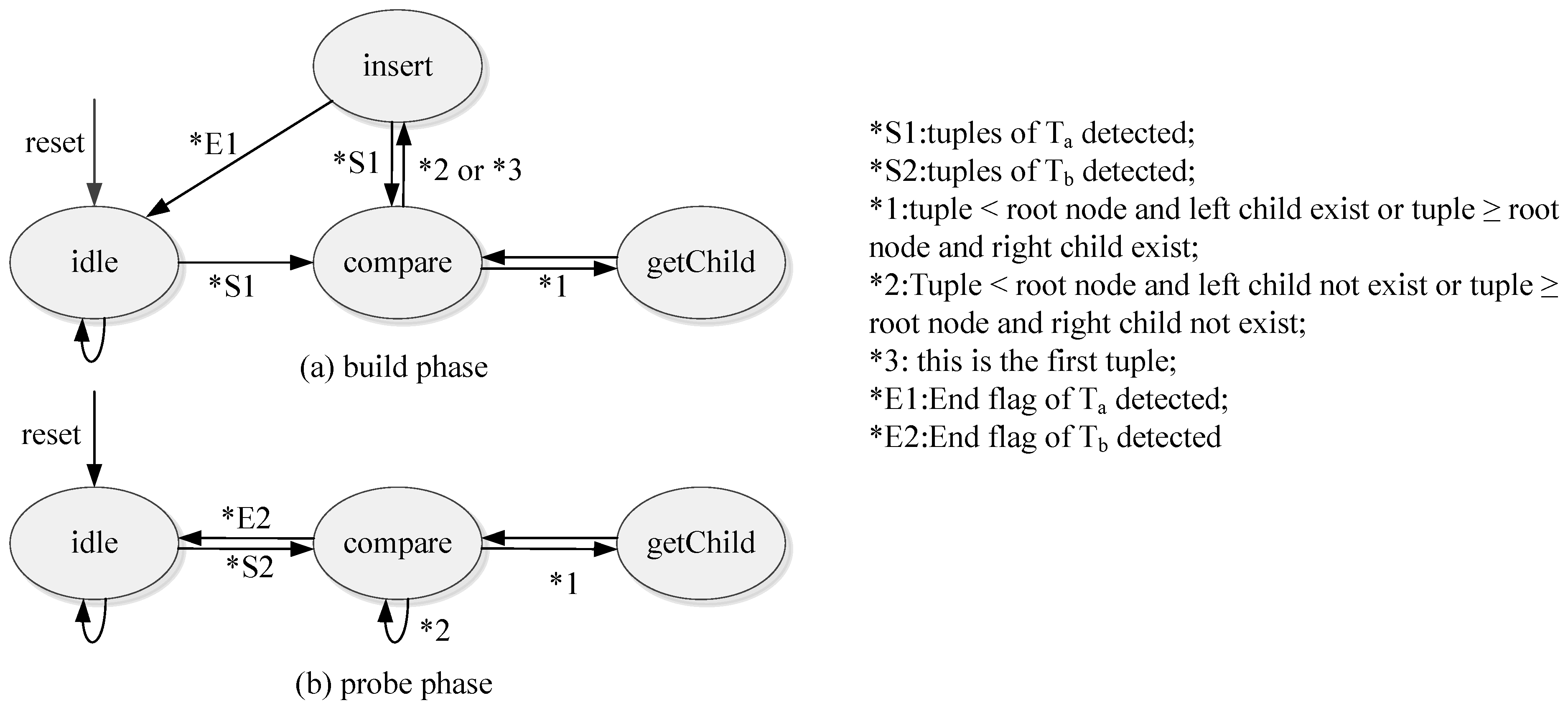
3.3. The Working Principle of the Controller
- (1)
- Build phase
During the build phase, the controller is driven by the finite state machine as shown in Figure 5a. To improve the performance, the tree tables are implemented by the dual-port BRAM. We can assess two addresses of a dual-port BRAM simultaneously. After the reset, the state machine enters the idle state and stays in this state until arrives. Every tuple of will be compared to the root node as the state machine is in the compare state. If the tuple is smaller than the root node and the root has no left child, or if the tuple is larger than or equal to the root node and the root node has no right child, the state machine will enter the insert state, and the controller will insert the tuple into the BRAM and update the root node’s lpt or rpt field to the new address, respectively. If the tuple is smaller than the root node and the root has a left child, or if the tuple is larger than or equal to the root node and the root node has a right child, the state machine enters the getChild state. Then the corresponding child node will be read from the tree table as a new root node, and the comparison process will be continued.
The build phase described above ends once all the tuples of are inserted into the address table.
- (2)
- Probe phase
The probe phase starts when streams in. During the probe phase, the controller is driven by the finite state machine as shown in Figure 5b. The state machine enters the idle state from the reset until a tuple of is detected. Similar to the build phase, the state machine enters the comparison state and the controller fetches the tuple from the FIFO and the root node from the tree table. If the tuple is smaller than the root node and the root node has a left child, or if the tuple is larger than or equal to the root node and the root node has a right child, the state machine enters the getChild state, reads the left or right child node, respectively, from the tree table as a new root node and continues the comparison process. If the tuple is smaller than the root node and the root node has no left child, or if the tuple is larger than or equal to the root node and the root node has no right child, the controller will fetch a new tuple and start a new process. Whenever the controller finds the tuple that equals the root node, it will output a join result.
The probe phase lasts until all the tuples of have been processed.
4. Analysis
4.1. The Average Number of Cycles to Process a Tuple
We use and to denote the average number of cycles needed to process a tuple in the build phase and probe phase, respectively. The sizes of and are denoted as and . and are proportional to the average number of comparisons needed to insert or search a tuple and are also inversely proportional to the number of channels C. It has been proven [12] that searching for a tuple in a binary search tree built from N random keys requires comparisons. In our design, every comparison requires two clock cycles, and it is clear here that . When we use a random number, our architecture needs an average number of clock cycles that can be calculated as follows:
4.2. Throughput Improvement by BF
Let m be the length of the bit vector used in the BF and k be the number of hash functions. We can conduct a false positive rate p when looking up a key in the BF:
We can minimize the false positive rate p for a fixed m and by using k hash functions: . When using the optimized k, we can obtain the relation between m and p: . In our design, we try to minimize the false positive rate r via optimizing k and corresponding m.
We divide into two sub-tables ( and ), where tuples in can find a match with while tuples in cannot. The sizes of these two sub-tables are denoted as and , respectively. In this way, the match rate r which measures how many tuples in can find a match in is given by:
Without BF, the number of clock cycles required to perform a join query is . While using BF with a false positive rate p, the number of clock cycles needed is . Assuming and , for simplicity, the throughput improvement using BF is given by
We can see the maximum and minimum improvement are met when r = 0 and 1, respectively. When , , and , the improvement will be maximized to .
5. Evaluation
In this section, we present the setup of the experiments, along with the performance and resource utilization of the proposed architecture. All the tuples are in the 48 bit format with a 32 bit key and a 16 bit id.
Experiment Setup
To utilize this join architecture, we always considered the smaller table as the and the larger table as . Thus, in our experiment, we used two tables of the same size (). We tested the performance of our architecture under different table sizes, numbers of channels and match rates. The table sizes l were set to 4K (4096), 8K (8192), 16K (16,384), 32K (32,768) and 64K (65,536). The number of channels was set to 4, 8 and 16. The match rate r was set to 0.1, 0.5, and 0.9 to observe the performance improvement by BF when the match rate was low. For a fixed l and r, we generated our and as follows: the ids in both tables were the same ordinal number from 0 to . To generate the key for every column, we first generated a random number from 0 to 1. If it was less than r, we generated a 32 bit key randomly. This key was used for both and ; otherwise, we generated two different keys randomly for and , respectively.
For every l, r combination, we generated and 10 times. We conducted an average of 10 experiments to test the performance of our work under specific l, r and C conditions.
Although we could obtain a higher throughput using BF with a smaller false positive rate p, this would more resources, including BRAMs, control logics and clock cycles. Because the BRAM supports the dual-port mode naturally, we defined the number of hash functions k to be 2. If k were larger than 2, it would cause stalls when writing or reading k positions in the BRAM. With a fixed k, the larger the m value used, the fewer false-positives p obtained. The design of this architecture makes a trade-off between m and p. In our design, we chose and , resulting in .
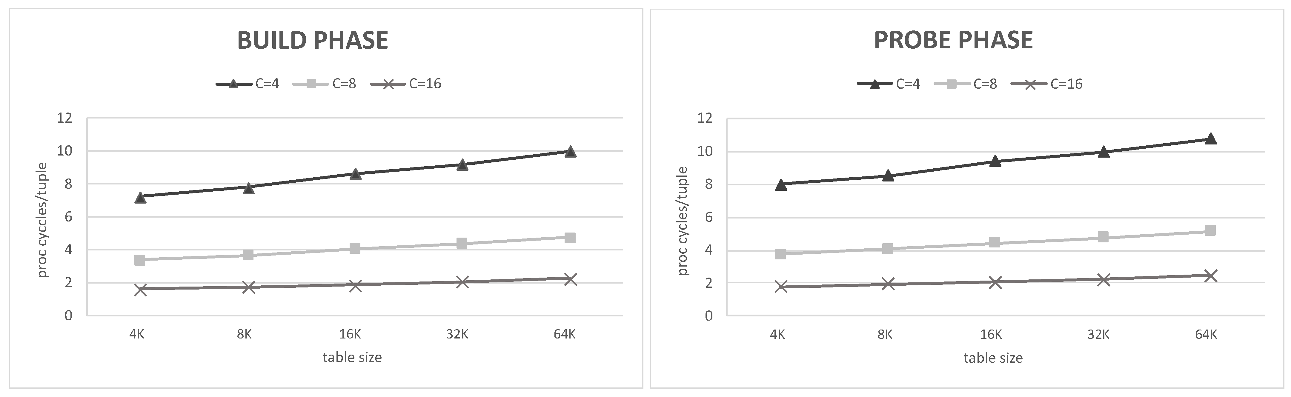
The average number of cycles and to process a tuple in the build phase and probe phase influenced the throughput. Thus, we examined and concerning different numbers of channels C and different table sizes l. Because tuples may not be perfectly distributed to different channels uniformly, we began to count when the first tuple streamed in and stopped counting when all of the tuples were stored in the BRAMs in different channels. We calculated using the total number of clock cycles of a join query minus .
Figure 6 shows our actual experimental and concerning C and l. The data used here corresponded to a match rate r = 1 to eliminate the influence of BF. A consistent result with Equation (1) was shown; i.e., that and were almost the same and adding channels sharply reduced both and . The growth rate of both and was reducdd with more channels.
FPGA utilization was estimated under different C values of 4,8 and 16, respectively. This was compared with the previous work listed in Table 1. The listed throughput was measured using a table size of K and match rate of . To ensure a fair comparison with previous studies, we used the metric of the throughput-to-power ratio. The result shows that our work has a higher throughput and is still more energy-efficient than previous works.
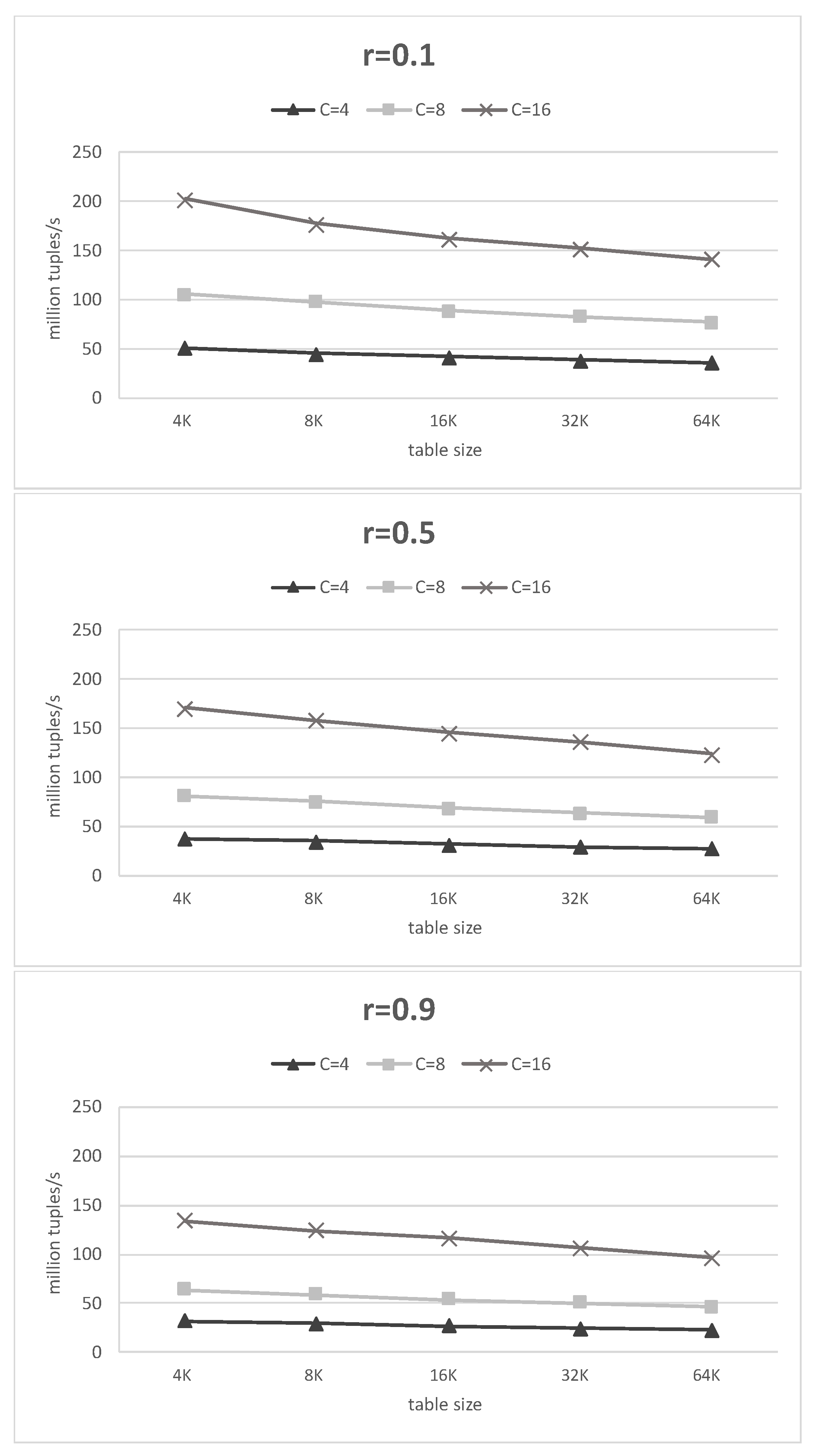
The reported throughput is an average throughput of the build phase and probe phase. Figure 7 shows the throughput for different numbers of channels, table sizes and match rates. We can see that the more channels we used and the lower the match rate of the table, the higher the throughput we could obtain. This means that, unlike previous work, the proposed architecture may have a higher throughput with a lower match rate. Moreover, the performance can be further improved by adding channels at the cost of using more resources.
6. Conclusions
This study proposed an FPGA accelerator architecture for join operations that can improve the performance of join queries in relational database systems. In our design, multiple address tables were adopted to reduce the average depth of the binary tree structure. A Bloom filter was used to reduce the search time. We analyzed the average clock cycles needed to process a tuple and the performance improvement using the Bloom filter. The experimental result was consistent with our analysis, showing that our design is more energy-efficient than previous work. Specifically, the proposed architecture achieved a throughput of 145.8 million tuples per second with a match rate of 50%.
Author Contributions
Conceptualization, B.H., M.X., S.L. and W.L.; Investigation, B.H.; Methodology, B.H. and M.X.; Validation, B.H. and S.L.; Writing—original draft, B.H.; Writing—review & editing, B.H. and W.L. All authors have read and agreed to the published version of the manuscript.
Funding
This research received no external funding.
Conflicts of Interest
The authors declare no conflict of interest.
References
- Shirazi, N.; Benyamin, D.; Luk, W.; Cheung, P.Y.K.; Guo, S. Quantitative Analysis of FPGA-Based Database Searching. J. VLSI Signal Process. Syst. 2001, 28, 85–96. [Google Scholar] [CrossRef]
- Kritikakis, C.; Chrysos, G.; Dollas, A.; Pnevmatikatos, D.N. An FPGA-Based High-Throughput Stream Join Architecture. In Proceedings of the 2016 26th International Conference on Field Programmable Logic and Applications (FPL), Lausanne, Switzerland, 29 August–2 September 2016; pp. 1–4. [Google Scholar] [CrossRef]
- Owaida, M.; Sidler, D.; Kara, K.; Alonso, G. Centaur: A Framework for Hybrid CPU-FPGA Databases. In Proceedings of the 2017 IEEE 25th Annual International Symposium on Field-Programmable Custom Computing Machines (FCCM), Napa, CA, USA, 30 April–2 May 2017; pp. 211–218. [Google Scholar] [CrossRef]
- Papaphilippou, P.; Pirk, H.; Luk, W. Accelerating the Merge Phase of Sort-Merge Join. In Proceedings of the 2019 29th International Conference on Field Programmable Logic and Applications (FPL), Barcelona, Spain, 8–12 September 2019; pp. 100–105. [Google Scholar] [CrossRef]
- Casper, J.; Olukotun, K. Hardware Acceleration of Database Operations. In Proceedings of the 2014 ACM/SIGDA International Symposium on Field-Programmable Gate Arrays (FPGA ’14); Association for Computing Machinery: New York, NY, USA, 2014; pp. 151–160. [Google Scholar] [CrossRef]
- Chen, R.; Prasanna, V.K. Accelerating Equi-Join on a CPU-FPGA Heterogeneous Platform. In Proceedings of the 2016 IEEE 24th Annual International Symposium on Field-Programmable Custom Computing Machines (FCCM), Washington, DC, USA, 1–3 May 2016; pp. 212–219. [Google Scholar] [CrossRef]
- Zhou, Z.; Yu, C.; Nutanong, S.; Cui, Y.; Fu, C.; Xue, C.J. A Hardware-Accelerated Solution for Hierarchical Index-Based Merge-Join. IEEE Trans. Knowl. Data Eng. 2019, 31, 91–104. [Google Scholar] [CrossRef]
- Werner, S.; Groppe, S.; Linnemann, V.; Pionteck, T. Hardware-Accelerated Join Processing in Large Semantic Web Databases with FPGAs. In Proceedings of the 2013 International Conference on High Performance Computing Simulation (HPCS), Helsinki, Finland, 1–5 July 2013; pp. 131–138. [Google Scholar] [CrossRef]
- Halstead, R.J.; Sukhwani, B.; Min, H.; Thoennes, M.; Dube, P.; Asaad, S.; Iyer, B. Accelerating Join Operation for Relational Databases with FPGAs. In Proceedings of the 2013 IEEE 21st Annual International Symposium on Field-Programmable Custom Computing Machines, Seattle, WA, USA, 28–30 April 2013; pp. 17–20. [Google Scholar] [CrossRef]
- Xue, M.T.; Xing, Q.J.; Feng, C.; Yu, F.; Ma, Z.G. FPGA-Accelerated Hash Join Operation for Relational Databases. IEEE Trans. Circuits Syst. II Express Briefs 2020, 67, 1919–1923. [Google Scholar] [CrossRef]
- Zhang, H.; Zhao, B.; Li, W.; Ma, Z.; Yu, F. Resource-Efficient Parallel Tree-Based Join Architecture on FPGA. IEEE Trans. Circuits Syst. II Express Briefs 2019, 66, 111–115. [Google Scholar] [CrossRef]
- Sedgewick, R.; Wayne, K. Algorithms; Addison-Wesley Professional: Boston, MA, USA, 2011. [Google Scholar]
Figure 1.
An example of an equi-join.

Figure 2.
Example of Bloom filter.

Figure 3.
An example of the binary tree model.

Figure 4.
The proposed overall architecture. The tuples of the input sequence are in the {id, key} format in both the build and probe phase. The tuples of the output sequence are in the {ida, idb, key} format.
Figure 4.
The proposed overall architecture. The tuples of the input sequence are in the {id, key} format in both the build and probe phase. The tuples of the output sequence are in the {ida, idb, key} format.

Figure 5.
State diagram of the FSMs used in the build phase and probe phase.

Figure 6.
The average number of cycles per tuple in build phase and probe phase.

Figure 7.
Throughput results under different conditions.


Table 1.
Comparison with previous works. Each work’s power consumption is estimated using Xilinx Power Estimator. The ratio is throughput-to-power.
Table 1.
Comparison with previous works. Each work’s power consumption is estimated using Xilinx Power Estimator. The ratio is throughput-to-power.
| Method | Platform | Frequency (MHz) | LUTs | Registers | BRAMs (KB) | Power (W) | Throughput (million-tuples/s) | Ratio |
|---|---|---|---|---|---|---|---|---|
| [8], AHJ | Xilinx Virtex-6 | 200 | 1200 | - | 135 | 0.402 | 1.8 | 4.5 |
| [9] | Altera Stratix IV | 200 | 14,862 | 13,170 | 597 | 1.983 | 18 | 9.1 |
| [11], T = 4 | Xilinx Zynq | 349 | 1706 | 2238 | 162 | 0.847 | 14.9 | 17.6 |
| [11], T = 8 | Xilinx Zynq | 261 | 3744 | 4842 | 162 | 0.807 | 28.9 | 35.8 |
| [11], T = 16 | Xilinx Zynq | 261 | 7820 | 10,050 | 180 | 1.144 | 62.4 | 54.5 |
| [6] | Xilinx Zynq | 100 | 42,609 | 27,838 | 468 | 1.406 | 86 | 61.2 |
| [10] | Xilinx Zynq | 280 | 3098 | 2572 | 261 | 1.035 | 83.83 | 81.0 |
| This work, C = 4 | Xilinx Zynq | 238 | 1730 | 2180 | 189 | 0.673 | 33.6 | 49.9 |
| This work, C = 8 | Xilinx Zynq | 233 | 3593 | 4353 | 189 | 0.775 | 70.0 | 90.3 |
| This work, C = 16 | Xilinx Zynq | 228 | 6818 | 8354 | 189 | 0.959 | 145.8 | 152.0 |
Publisher’s Note: MDPI stays neutral with regard to jurisdictional claims in published maps and institutional affiliations. |
© 2021 by the authors. Licensee MDPI, Basel, Switzerland. This article is an open access article distributed under the terms and conditions of the Creative Commons Attribution (CC BY) license (https://creativecommons.org/licenses/by/4.0/).
Share and Cite
MDPI and ACS Style
He, B.; Xue, M.; Liu, S.; Luo, W. Bloom Filter-Based Parallel Architecture for Accelerating Equi-Join Operation on FPGA. Electronics 2021, 10, 1778. https://0-doi-org.brum.beds.ac.uk/10.3390/electronics10151778
AMA Style
He B, Xue M, Liu S, Luo W. Bloom Filter-Based Parallel Architecture for Accelerating Equi-Join Operation on FPGA. Electronics. 2021; 10(15):1778. https://0-doi-org.brum.beds.ac.uk/10.3390/electronics10151778
Chicago/Turabian StyleHe, Binhao, Meiting Xue, Shubiao Liu, and Wei Luo. 2021. "Bloom Filter-Based Parallel Architecture for Accelerating Equi-Join Operation on FPGA" Electronics 10, no. 15: 1778. https://0-doi-org.brum.beds.ac.uk/10.3390/electronics10151778
Note that from the first issue of 2016, this journal uses article numbers instead of page numbers. See further details here.