
Efficient Holographic Focusing Metasurface


Center of Metamaterials and Integrated Plasmonics, Department of Electrical and Computer Engineering, Duke University, Durham, NC 27708, USA
*
Author to whom correspondence should be addressed.
Electronics 2021, 10(15), 1837; https://0-doi-org.brum.beds.ac.uk/10.3390/electronics10151837
Submission received: 12 June 2021
/
Revised: 15 July 2021
/
Accepted: 20 July 2021
/
Published: 30 July 2021
(This article belongs to the Special Issue Wireless Power/Data Transfer, Energy Harvesting System Design, Volume II)
Abstract
:We present the design and experimental demonstration of an efficient holographic metasurface aperture that focuses microwaves in the Fresnel zone. The proposed circular structure consists of two stacked plates with their periphery terminated in a conductive layer. Microwaves are injected into the bottom plate, which forms the feed layer, and are coupled to the top holographic metasurface layer via an annular ring. This coupling results in an inward traveling cylindrical wave in the top layer, which serves as the reference wave for a hologram. The radiating elements consist of a slot pair with their orientations designed to couple efficiently with the cylindrical reference wave while maintaining a linearly polarized focused beam. A general condition on the slot pairs radiated power is proposed to ensure low sidelobe level (SLL) and is validated with full-wave simulation. An aperture that is 20 cm in diameter, operates at 20 GHz in the K-band frequency, and forms a diffraction-limited focal spot at a distance of 10 cm is experimentally demonstrated. The proposed near-field focusing metasurface has high antenna efficiency and can find application as a compact source for Fresnel-zone wireless power transfer and remote sensing schemes.
1. Introduction
Near field focused antennas are of interest in the microwave and millimeter wave frequencies for a variety of applications such as remote sensing, medical targeting devices, internet of things and wireless power transfer [1,2,3,4,5,6,7,8,9,10,11,12,13]. They are referred to as near-field focusing structures since they concentrate electromagnetic fields to a spot in the Fresnel region, i.e., at distances , where D is the aperture dimension and is the wavelength. Their operation is based on forming an aperture field distribution that constructively interferes at a given focal spot located in the Fresnel region. Various methods have been proposed to realize such behavior. The common practice is to use antenna arrays with elements whose amplitudes and phases are selected to approximate the aperture distribution [10,11]. The required complex amplitude is usually realized via an intricately designed feed network or a phased array [8,12,14,15,16]. In the former case, the feeding network can become too complicated as the aperture size grows or the frequency of operation is increased. The latter case suffers from cost, high power consumption, and complications associated with phase shifters. Another method is to use the Fresnel zone plate (FZP) where promising results have been demonstrated, but the large form factor inevitable in such structures limits their use in most applications [17].
Leaky-wave (LW) and modulated-impedance surface antennas have also been proposed and experimentally demonstrated to generate desired focal spots [18,19,20,21,22,23,24,25,26,27,28,29]. Their operation is based on gradual perturbation of a guided mode to form converging leaky modes that interfere constructively at a focal spot. Realizing this condition usually requires a degree of cylindrical symmetry, which tends to result in a longitudinal electric field at the focal spot, a property that can complicate receiver design. In addition, a leaky-wave antenna’s ability to steer the focus is reliant on changing the driving frequency, another factor that may complicate the source and detector circuitry.
Metasurface holograms designed to interact with a guided wave are another hardware system suggested for near-field focusing applications [13,30,31]. These structures consist of an array of metamaterial elements forming a hologram that approximates the field distribution, which results in the desired focus. In this framework, the element distribution and orientation can be arbitrary and are not limited to configurations that generate converging leaky modes. As a result, metasurface holograms offer more freedom in designing focal spots with desired attributes. For example, in contrast to the leaky-wave structures of [20,27], metasurface holograms do not need to be cylindrically symmetric, allowing them to avoid undesired longitudinal components at the focal spot. Meanwhile, metasurface holograms offer the same practical advantages of leaky-wave antennas, i.e., they have low manufacturing costs and a planar form factor, making them a suitable candidate for applications related to beam forming and wavefront shaping [32,33,34,35,36,37].
Since the operation of a metasurface hologram requires the interaction of a guided wave with an arrangement of metamaterial elements, the guided wave inevitably attenuates, which can lead to severe deviation of the resulting pattern from the desired focal pattern (e.g., undesired large sidelobes). To combat this problem, previous holographic metasurface designs used a configuration commonly referred to as radial line slot array antenna (RLSA) [22,38,39,40,41,42,43,44,45,46,47,48,49,50,51]. The dual-layer RLSA design [38,39,40,41,42] uses a converging cylindrical guided wave. The field amplitude of a converging cylindrical wave increases as it travels along the waveguide towards the center. This increase in the field amplitude can be used to compensate for the decay of the field amplitude due to the radiation losses, resulting in a more uniform amplitude distribution on the aperture. This configuration has been widely used before to generate directive field patterns in the far field useful in satellite communication [39,40]. A table showing the different architectures from literature which are used in realizing a focused aperture along with their advantages and disadvantages is mentioned in comparison with the current manuscript is presented in Table 1. This table is essentially the visualization of the introduction of the manuscript.
In this work, we also use a double layer RLSA configuration to excite a hologram to focus on the Fresnel zone at 20 GHz which is in the K-band frequency regime (18–27 GHz). This is distinct from previous works that used RLSA structures to generate Bessel or Gaussian beams in the near field [28,29,50]. Here, we revisit the holographic design process of [30] and make two important modifications to address its shortcomings. First, inspired by the common practice in the literature, we replace the single slot with a slot pair to improve efficiency while ensuring desired polarization at the focal spot [43,51,52]. Next, we outline a simple intuitive method to compensate the field radiated by the slot pair by the converging field of the guided wave, demonstrating a mechanism to tailor the properties of the focal patterns. Both proposed modifications are demonstrated in full wave simulation and experiments. The simulated combined efficiency of the aperture is higher than previous works (≈48%) will the SLLs below dB. Side lobe level (SLL) which is defined as of the amplitude at the peak of the main lobe to the amplitude at the peak of a side lobe as mentioned in the literature [53].
2. Materials and Methods
2.1. Focusing Holographic Metasurface Design
We follow a similar design process as in [30] but with a few modifications. First, we design a phase hologram disregarding the amplitude variation on the surface of the hologram. Then we investigate mechanisms to tailor the amplitude profile at the surface of the hologram (and consequentially the focal spot characteristics) without modifying the phase hologram.
Design of the phase hologram starts by computing the field profile produced across the metasurface due to a virtual point source at the location of the desired focus. Considering the center of the aperture as the origin of the coordinate system, a point source generates a field profile on the aperture given by [30]:
where k is the wavenumber in freespace, is the desired focal point and C is a normalization constant.
The quantity A here is assumed to be unit-less and to represent the field variation across the aperture. We next design a hologram to generate such a field variation. To do that, we note the widths of the slots constituting the hologram are relatively small (compared to the free space wavelength). Thus, their electromagnetic response is well approximated by a magnetic dipole by means of the surface equivalence principle [54,55,56]. As a result, the slots couple primarily to the magnetic field of the guided wave, whose phase and amplitude variation are given by the Hankel function of the first kind (assuming convention):
where is the wavenumber within the waveguide, is the rotation angle in the transverse plane () of the aperture defined with respect to the x-axis and is the position of the discretized point on the aperture. For simplicity, we have considered as a unitless variable. This choice is justified as we are interested in designing a phase-only hologram. That is to say, we disregard the amplitude variation of A and . To form a focus, the guided wave inside the waveguide should excite metasurface elements such that they realize the phase profile given by A. This condition is met at locations where the product of the complex conjugate of A and yields a zero phase.
The (phase) hologram can then be realized by placing a radiating element at each position where the phase of U is zero. Practically, locations that satisfy this condition are too close to each other, preventing us from placing finite size metamaterial radiating elements. To accommodate this consideration we discretize the aperture and place radiating elements at locations where the phase of U in Equation (3) is less than radians (obtained empirically). It is important to note that in the above, we have assumed the radiating elements perturb neither the guided wave’s phase progression nor its magnitude. This condition can be approximately satisfied in practice by using radiating elements away from their resonances.
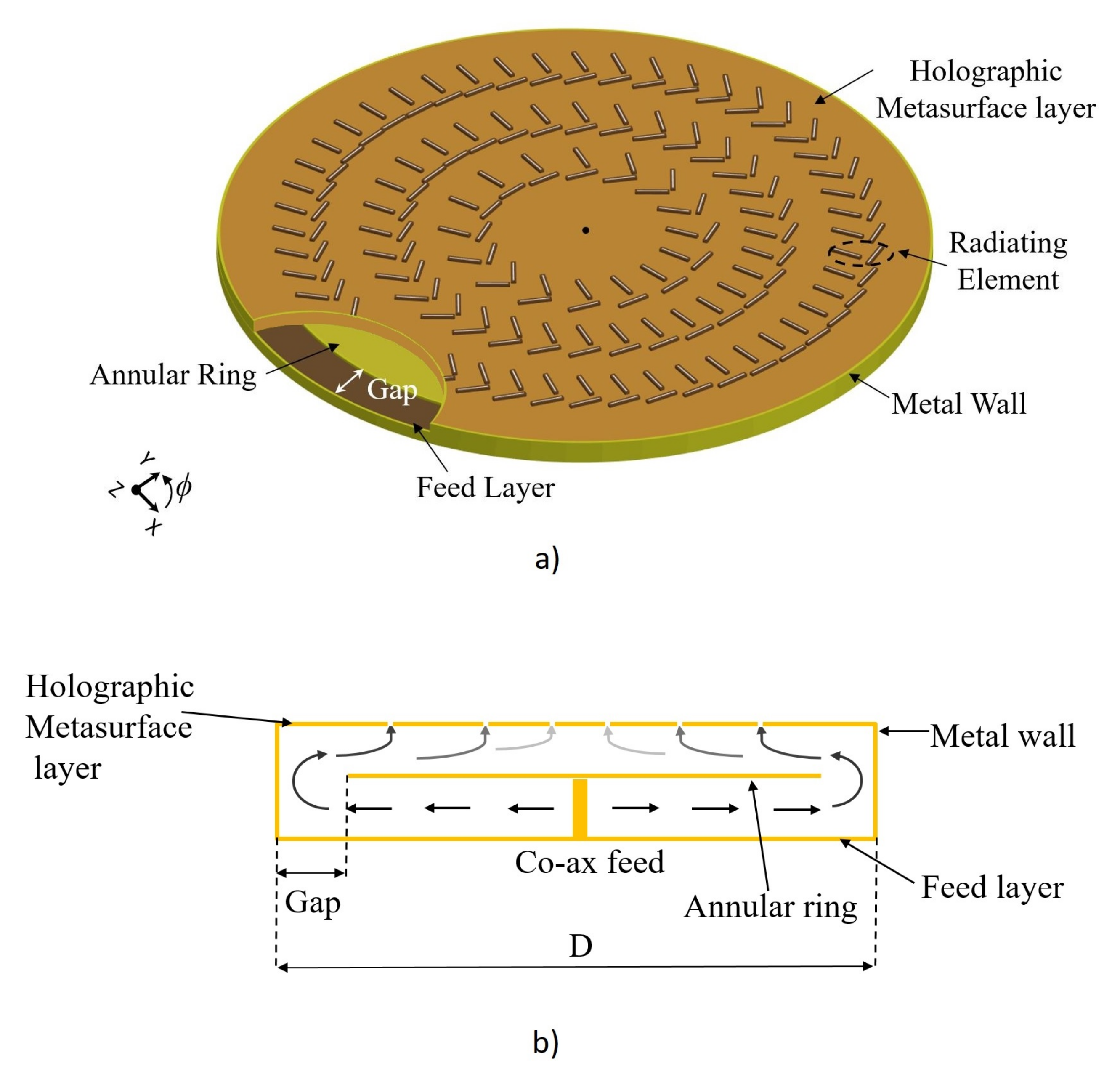
As discussed earlier, we use a double-layer metasurface configuration shown schematically in Figure 1. In this configuration, a coaxial connector produces an outward cylindrical wave in the bottom layer which is transformed into an inward traveling wave in the top layer by an annular ring. As a result, the reference wave for the focusing hologram is an inward traveling cylindrical wave given by the first order hankel function of the first kind. To simplify the design process, we consider substrates with thicknesses that are less than (where is the guided wavelength) in order to support only a single mode in each substrate.
In [30], single slots oriented parallel to each other and to the y-axis were used as the radiating elements. This choice guaranteed the electric field at the focal plane was linearly polarized along the x-direction. This arrangement, while simple in design, suffers from a practically important drawback: the radiation from the slots depends heavily on the angle between the slots and the magnetic field of the guided wave. This results in regions where the slots do not contribute to the focus. This resulted in reducing the effective area of the aperture, manifested as high sidelobes at the focal plane and low radiation efficiency [30]. To overcome these deficiencies, we employ the slot pair [51] as a single radiating element. A slot pair is defined as two slots arranged in a manner so that together they couple to the guided wave at all locations on the aperture while maintaining a single polarization. Later, we will examine the radiated power from each element and outline conditions to ensure low SLLs based on the elements’ amplitudes.
2.2. Amplitude Profile and Role of the Inward Traveling Wave
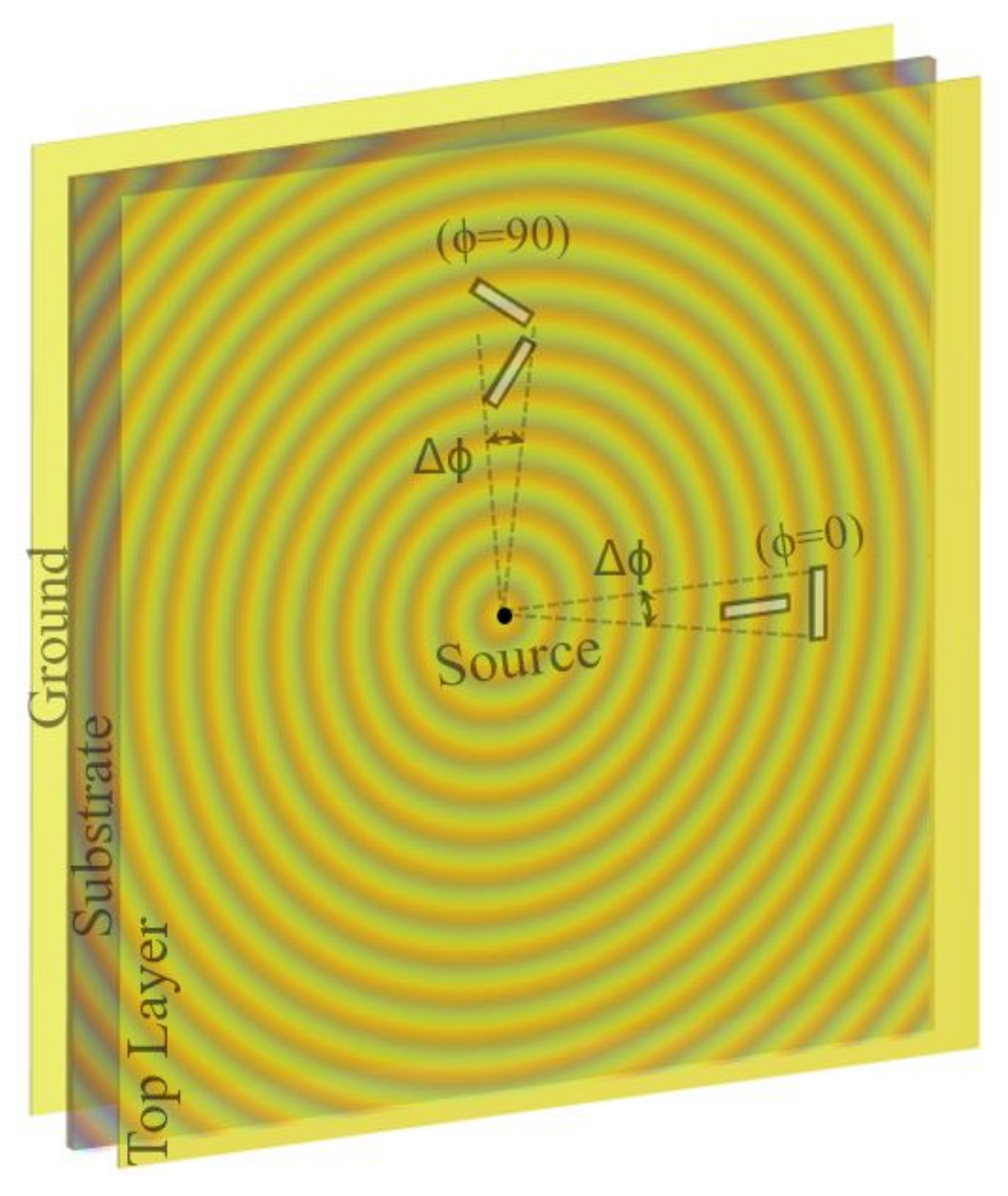
As discussed earlier, the primary reason behind using inward a traveling cylindrical wave is its ability to compensate for the loss of the guided wave due to radiation. In some previous works, it was suggested that this condition can only be satisfied in substrates with dielectric constant between to [51]. Here, we propose to use the coupling strength of the radiating element as a means to modify the amplitude profile without any limitation on the substrate choice or element distribution (which dictates the phase profile). We begin by examining the power radiated by a slot pair in a parallel plate waveguide using CST simulations, as shown in Figure 2. The parallel plate waveguide is excited by a cylindrical source (e.g., a coaxial connector) at the center and perfect matched layers terminate its periphery. This simulation allows us to examine the overall coupling of the slot pair (i.e., decay of the guided wave due to its radiation).
First, we confirm the proposition that the power radiated by a slot pair configuration is indeed linearly polarized. To this end, we have calculated the power radiated in both the co-polarization (co-pol) and cross-polarization (cross-pol) as a percentage of the incident power on the element at two different locations on the aperture ( and ) as shown in Figure 2. For this simulation, we have used a substrate with a dielectric constant and (similar to the one used later in experimental studies). The incident power on the slots pair is calculated by multiplying the accepted power by the coaxial connector, , with the angle subtending the element, , as denoted in Figure 2 (for more information, see Appendix B of [57]):
The radiated power in each polarization is computed by CST ( can be co-pol or cross pol). For comparison, we have done this study using both a single slot and a slot pair, results are shown in Figure 2.
SAs shown in Table 2, when the element is placed at , both the single slot and the slot pair radiate similar and sufficient power in the co-pol, while they both radiate minimal amount of power in the cross pol. However, when the radiating element is placed at , the coupling of the single slot is minimal since it is orthogonal to the exciting magnetic field. In contrast, the slot pair generates the desired co-pol radiation with the radiated power close to that observed when the element is at . The radiated power into the cross polarization from the slot pair is minimal in this location as well. It is worth noting that for all locations in between these two extreme cases, the power radiated by either elements is between the values reported in Table 2. It is important to note that similar results can be obtained for slots designed for substrates with dielectric constants out of 1.5–2.5 range. Those results are presented in Section 3.1.1 (dielectric constant of 4 which is out of the ranger of 1.5–2.5) where the design of a focusing metasurface aperture with low SLL using the condition in (6) is successfully presented.
Next, we examine the possibility to modify the amplitude profile across the hologram and consequently tailor the characteristics of the focus. Among various aspects of the focus, ensuring low SLLs is critical for focusing applications and we set our objective to realize low SLLs. High SLLs occur when the radiated fields closer to the edge are higher than the ones near the center. This happens when the increase in the field density of the inward traveling wave cannot compensate the decay due to radiation from slot pairs. Using the results in Table 2 as our guide, we can see the maximum of radiation losses happen when . We then define a design parameter that accounts for the percentage of the inward traveling wave that passes through a slot pair without being radiated. Mathematically, this parameter can be described as:
The values reported in Table 2 are essentially for different elements in percentage.
As the wave traverses from the outermost ring, located at r, and arrives at the second ring, located at , the power incident on the slot pair increases by due to the inward traveling wave—this is based on the assumption that r is large enough that we can use large argument approximation for the Hankel function describing the reference wave. To realize low SLLs, we need to ensure that the inward traveling wave compensates for the power decay due to radiation losses, i.e.,
In our design, is usually on the order of a guided wavelength (). It is worth noting that according to Table 2, we only need to compute this ratio for the element at , where the power radiated is strongest. Furthermore, if we guarantee the condition provided in (6) for the outermost elements, it automatically ensures it for all other elements located at inner rings. In this manner, we guarantee the aperture field distribution is relatively uniform, ensuring low SLLs. It is also worth emphasizing that (6) provides us with a design mechanism: for a given substrate (even if it is out of the range of 1.5 to 2.5) and phase profile, we can manipulate the slot’s lengths to ensure the desired amplitude profile. This proposal is verified in the next section by examining a substrate with a large dielectric constant.
3. Results
3.1. Full-Wave Simulation Results
3.1.1. High Dielectric Constant Substrate
First, we demonstrate that our proposed condition, (6), guarantees low SLLs. We design an aperture using a substrate with dielectric constant of 4. This value is out of the range of 1.5–2.5 suggested by [51]. We design this structure to operate at 20 GHz. Considering the limitations of simulation time, the aperture size (D) was chosen to be a modest 10 cm in diameter. The resonant frequency (≈23 GHz) of the slots was intentionally selected to be shifted from the operating frequency (20 GHz) so that the elements are weakly coupled to the guided mode. Highly resonant elements can perturb the guided wave, which would violate our design assumptions. The slot length and width corresponding to this resonant frequency are mm and mm, respectively. Using the design procedure outlined in Section 2 for a phase hologram, this structure is designed and simulated using CST. The resulting focal pattern is shown in Figure 3a. It should be emphasized that the apertures examined throughout this manuscript have relatively low Fresnel number which leads to a phenomenon called focal shift where the peak intensity is not at the intended focal plane. This phenomenon is well studied in the literature and an explanation is not repeated here [30,58,59,60,61].
While the focus for the designed aperture is evident in Figure 3, we can see high sidelobes. If we compute the ratio given by (6) for this structure it is , which is below 1 (see Table 3). This can be explained by noting the fact, as the substrate dielectric constant increases, the spacing between the rings, (), decreases. As a result, the compensation of the guided wave field density due to the convergence decreases.
To combat this issue, as proposed in the previous section, we need to design elements with lower coupling, i.e., higher . To do this, the slot length is varied until the desired level of is achieved and we meet the condition of (6). The new slot length is mm (which is resonant at around 24 GHz). The exact values for the design ratio is presented in Table 3. This slot length is then used to implement the holographic aperture. The simulated focal pattern generated by this design using CST is also shown in Figure 3, clearly exhibiting lower SLLs compared to the case where the design condition (6) was not satisfied. The lower limit in the cross range plots shown are set to (corresponding to dB) to further highlight the low SLLs. The results in Figure 3 clearly verify the importance of the condition given by (6) in designing the focusing holographic metasurface.
As mentioned earlier in the paper, having a fairly uniform field distribution on the aperture will alleviate the side lobe levels at the focal plane. Figure 4 shows the 1-D plot of the normalized electric field value along the horizontal axis (x-axis) which is indicated by the white line. The electric field values at the elements are obtained from CST simulations and later normalized to its maximum value as shown in the figure. The fairly uniform field values are evident for the case satisfying the condition in Equation (6), while the design where the elements are not satisfying the power condition show high variations. The field distributions for the case satisfying the power condition can be further improved by fine tuning the radiating elements to achieve a SLL lower than reported in Table 3 using more advanced modeling of the slots (for example using coupled dipole model [55,56]) and is the topic of our future investigations.
3.2. Low-Loss Substrate
In the previous subsection, we used a substrate with high dielectric constant to demonstrate the importance of our proposed design condition in realizing low SLLs. In this subsection, we design the aperture using substrates that are practically available. In doing so, we also illustrate the utility of the proposed slot pair in increasing antenna efficiency. Toward this goal, we first design an aperture similar to that of [30]. All the parameters, such as focal length, 10 cm, diameter, 10 cm, and operating frequency, 20 GHz, are the same with the key difference being the use of a slot pair instead of a single slot [30]. Using the procedure outlined in Section 2, we have designed the aperture and simulated it using CST using a low loss Rogers 5880 substrate. The efficiency of the designed aperture with slot pairs as radiating elements, in comparison to the ones reported in [30], is listed in Table 4. In the designs used for Table 4 the reflection coefficient () has been kept below dB by running a parametric sweep of the size of the annular gap [30]. The combined efficiency reported in Table 4 is calculated by multiplying the antenna efficiency and the focal efficiency. The antenna efficiency obtained from CST (referred to as total efficiency in CST) simulations accounts for the impedance mismatch. The focal efficiency is defined as the ratio of the power concentrated at the focal spot (an area of 2.25 × 2.25 cm is considered) to the power at the entire focal plane.
Examining Table 4 it is evident that the proposed design using slot pairs exhibits much higher efficiency, while keeping the SLL low. While the tapered design of [30] also has a low SLL, it has a fairly low combined efficiency in contrast to the design presented here. This is due to the fact that the tapering in [30] was designed without taking into account the polarization of the converging feed wave, and some radiating elements were selected to have very low radiated power. By taking into account the converging feed wave, we have designed the aperture amplitude profile that guarantees low sidelobe level, while maintaining high overall antenna efficiency. In Table 4, we can also identify that the improvement achieved in overall efficiency is accomplished by using slot pairs and a lower loss substrate.
Among the substrates available to us, Rogers 5880 offers the lowest losses and since low losses are crucial for our ultimate goal of focusing and transfer of power. If a substrate which has a low loss and a high dielectric constant which is above 2.5, it would be still be possible to design a focusing metasurface with low SLL. As a result, we redesigned the aperture using a substrate that has lower losses, i.e., mm thick Rogers 5880 substrate with and . The radiating slots are selected to be resonant at 23 GHz, which for , results in slots with length and width of mm and mm, respectively. Using the procedure outlined in Section 2, this aperture was designed and simulated using CST. The simulated combined efficiency for this design is also reported in Table 4 where we can see that using a lower loss dielectric has further increased the combined efficiency.
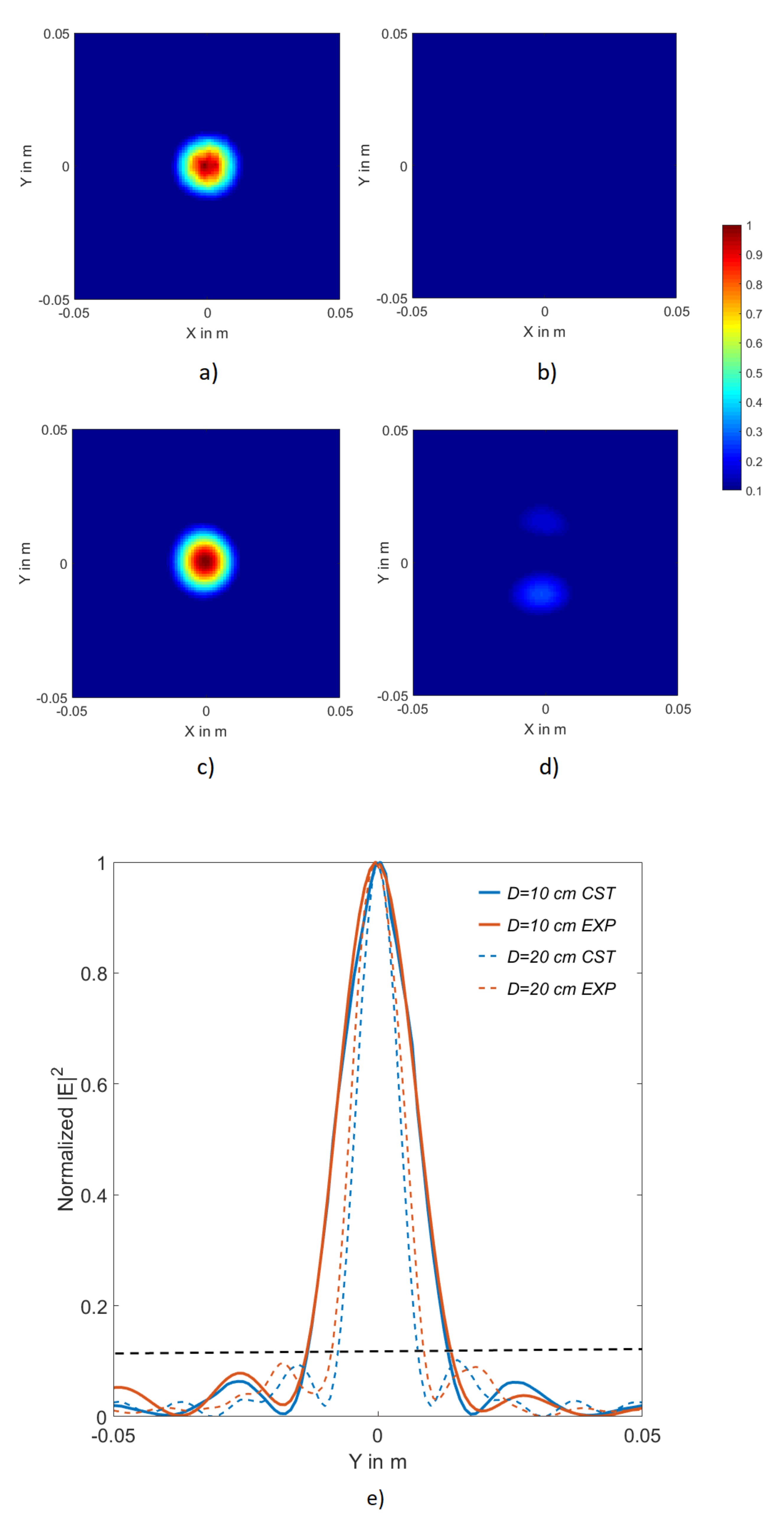
Next, we examine the simulated focal pattern, as shown in Figure 5a. A clear focal spot with low SLLs is evident. This is consistent with our predictions from Table 3 that such a slot pair satisfies our design condition for low SLLs (see (6)). It is also worth emphasizing that, as shown in Figure 5a, the designed aperture forms the focal spot with the desired polarization and the radiation into cross polarization is minimal.
3.3. Experimental Results
In this section, two different samples of the focused metasurface aperture are fabricated and experimentally examined. To fabricate each sample, the designed hologram was patterned onto the top layer of a double-sided copper-clad Roger 5880 substrate using a U3 LPKF laser milling system. The feed layer was also fabricated in a similar manner. The two waveguides were stacked on top of each other and copper tape was used to realize the cavity walls. The top, middle and the bottom layer of the sample with diameter 10 cm is shown in Figure 6a–c and another sample with diameter 20 cm is shown in Figure 6d.
First, we examine the aperture with D = 10 cm. The measured reflection coefficient, , of the focused aperture was below dB at the operating frequency. The fields generated at the focal plane are measured by performing a near-field scan of the aperture at a distance of 5 cm. The near field scan data were then propagated to the focal plane using a plane-to-plane propagator [62]. The experimental focal pattern computed in this manner is reported in Figure 5c, in comparison to the simulated one in Figure 5a—the two results exhibit close agreement. We have also measured the power radiated into the cross polarization, as shown in Figure 5d. Evidently, the aperture focused the power into the desired polarization. The slightly higher radiation into the cross polarization in the experimental results can be attributed to fabrication tolerances.
In Figure 5e, 1-D cross-range plots of the simulated and experimental focal spots are depicted. Excellent agreement between the two is observed, verifying the proposed design and operation. To highlight the low SLLs, a dashed line marks the dB level in Figure 5e.
Table 5 provides a comparison of the spot size values obtained from Gaussian optics [13], CST, and experiments. In our calculation using Gaussian Optics, we used the outer ring diameter as the aperture size (D). The points on the cross-range plot in Figure 5e are used for the calculations of the experimental spot size. Clearly, the experimentally measured values closely resemble the simulated ones, as well as the predicted values from Gaussian optics.
In most applications, there are harsh constraints on the size of the receiving aperture. To realize a smaller focal spot while also demonstrating the generality of our proposed design and operation, we have also designed a aperture to generate a focal spot at 10 cm. The cross-range plot of the focal spot generated by this aperture is also shown in Figure 5e (indicated by the dotted lines). We clearly see a smaller focal spot, while the SLL has stayed below the dB value. The focal spot examined in this paper is at a distance of 10 cm. Larger distances are desired in some applications. For such scenarios, we need to use larger physical apertures or higher frequencies (larger electrical size). However, full-wave simulations of such large structures with large focal distance may be prohibitively time and memory consuming. The close agreement presented in Figure 5e demonstrates that the proposed design procedure can be readily scaled.
4. Conclusions
This paper presented an efficient holographic metasurface to focus electromagnetic field when operating in the K-band frequency range. The functionality of the proposed aperture was verified with full-wave simulations and experiments. In this paper, carefully designed slot pairs were used as the radiating element for the metasurface, resulting in a considerable improvement in the combined efficiency of the aperture compared to the previously proposed design [30]. A simple condition to reduce the SLL in the focal plane was proposed and verified by CST simulations.
The radiating elements used in the current design have disadvantages in realizing a dynamic aperture. The phase introduced by the slots is constrained to a narrow set of values and hence the current design currently makes use of the phase associated with the guided mode propagation. However, when a metamaterial is accounted in designing the focused aperture along with the use of pin diodes makes the proposed architecture dynamic which is required for indoor application of wireless power transfer, remote sensing.
It should be noted that the design process proposed assumes a theory where the guided wave is unperturbed. However the entire focused aperture could be designed using the coupled dipole models where the physics of the aperture can be designed with higher precision. The physics include mutual interactions between the radiating elements which have been shown to be crucial in correlation to the radiation patterns [55,56]. Such rigorous models can be carefully considered in designing apertures with lower sidelobe levels and higher antenna efficiency. The focused aperture can find application in the field of wireless power transfer and remote sensing schemes.
Author Contributions
Conceptualization, V.R.G., T.S. and M.F.I.; methodology, V.R.G. and M.F.I.; software, V.R.G.; validation, V.R.G.; formal analysis, V.R.G. and M.F.I.; investigation, V.R.G.; resources M.F.I. and D.R.S.; data curation, V.R.G.; writing—original draft preparation, V.R.G.; writing—review and editing, V.R.G., M.F.I., T.S. and D.R.S.; visualization, V.R.G.; supervision, M.F.I. and D.R.S.; project administration M.F.I.; funding acquisition, D.R.S. All authors have read and agreed to the published version of the manuscript.
Funding
This work was supported by the Air Force Office of Scientific Research under Grants FA9550-12-1-0491 and FA9550-18-1-018.
Conflicts of Interest
The authors declare no conflict of interest. The funders had no role in the design of the study; in the collection, analyses, or interpretation of data; in the writing of the manuscript, or in the decision to publish the results.
References
- Tofigh, F.; Nourinia, J.; Azarmanesh, M.; Khazaei, K.M. Near-field focused array microstrip planar antenna for medical applications. IEEE Antennas Wirel. Propag. Lett. 2014, 13, 951–954. [Google Scholar] [CrossRef]
- Bogosanovic, M.; Williamson, A.G. Microstrip antenna array with a beam focused in the near-field zone for application in noncontact microwave industrial inspection. IEEE Trans. Instrum. Meas. 2007, 56, 2186–2195. [Google Scholar] [CrossRef]
- Stephan, K.; Mead, J.; Pozar, D.; Wang, L.; Pearce, J. A near field focused microstrip array for a radiometric temperature sensor. IEEE Trans. Antennas Propag. 2007, 55, 1199–1203. [Google Scholar] [CrossRef]
- Loane, J.; Lee, S.-W. Gain optimization of a near-field focusing array for hyperthermia applications. IEEE Trans. Microw. Theory Tech. 1989, 37, 1629–1635. [Google Scholar] [CrossRef]
- Ho, J.S.; Yeh, A.J.; Neofytou, E.; Kim, S.; Tanabe, Y.; Patlolla, B.; Beygui, R.E.; Poon, A.S. Wireless power transfer to deep-tissue microimplants. Proc. Natl. Acad. Sci. USA 2014, 111, 7974–7979. [Google Scholar] [CrossRef] [Green Version]
- Kim, S.; Ho, J.S.; Poon, A.S. Midfield wireless powering of subwavelength autonomous devices. Phys. Rev. Lett. 2013, 110, 203905. [Google Scholar] [CrossRef] [Green Version]
- Agrawal, D.R.; Tanabe, Y.; Weng, D.; Ma, A.; Hsu, S.; Liao, S.-Y.; Zhen, Z.; Zhu, Z.-Y.; Sun, C.; Dong, Z.; et al. Conformal phased surfaces for wireless powering of bioelectronic microdevices. Nat. Biomed. Eng. 2017, 1, 0043. [Google Scholar] [CrossRef]
- Buffi, A.; Nepa, P.; Manara, G. Design criteria for near-field-focused planar arrays. IEEE Antennas Propag. Mag. 2012, 54, 40–50. [Google Scholar] [CrossRef]
- Borgiotti, G.V. Maximum power transfer between two planar apertures in the fresnel zone. IEEE Trans. Antennas Propag. 1966, 14, 158–163. [Google Scholar] [CrossRef]
- Shan, L.; Geyi, W. Optimal design of focused antenna arrays. IEEE Trans. Antennas Propag. 2014, 62, 5565–5571. [Google Scholar] [CrossRef]
- Massa, A.; Oliveri, G.; Viani, F.; Rocca, P. Array designs for long-distance wireless power transmission: State-of-the-art and innovative solutions. Proc. IEEE 2013, 101, 1464–1481. [Google Scholar] [CrossRef] [Green Version]
- Gowda, V.R.; Yurduseven, O.; Lipworth, G.; Zupan, T.; Reynolds, M.S.; Smith, D.R. Wireless power transfer in the radiative near field. IEEE Antennas Wirel. Propag. Lett. 2016, 15, 1865–1868. [Google Scholar] [CrossRef]
- Smith, D.R.; Gowda, V.R.; Yurduseven, O.; Larouche, S.; Lipworth, G.; Urzhumov, Y.; Reynolds, M.S. An analysis of beamed wireless power transfer in the fresnel zone using a dynamic, metasurface aperture. J. Appl. Phys. 2017, 121, 014901. [Google Scholar] [CrossRef]
- Siragusa, R.; Lemaître-Auger, P.; Tedjini, S. Tunable near-field focused circular phase-array antenna for 5.8-ghz rfid applications. IEEE Antennas Wirel. Propag. Lett. 2011, 10, 33–36. [Google Scholar] [CrossRef]
- Khang, S.-T.; Lee, D.-J.; Hwang, I.-J.; Yeo, T.-D.; Yu, J.-W. Microwave power transfer with optimal number of rectenna arrays for midrange applications. IEEE Antennas Wirel. Propag. Lett. 2018, 17, 155–159. [Google Scholar] [CrossRef]
- Karimkashi, S.; Kishk, A.A. Focused microstrip array antenna using a dolph-chebyshev near-field design. IEEE Trans. Antennas Propag. 2009, 57, 3813–3820. [Google Scholar] [CrossRef]
- Karimkashi, S.; Kishk, A.A. Focusing properties of fresnel zone plate lens antennas in the near-field region. IEEE Trans. Antennas Propag. 2011, 59, 1481–1487. [Google Scholar] [CrossRef]
- Gomez-Tornero, J.L.; Quesada-Pereira, F.; Alvarez-Melcon, A.; Goussetis, G.; Weily, A.R.; Guo, Y.J. Frequency steerable two dimensional focusing using rectilinear leaky-wave lenses. IEEE Trans. Antennas Propag. 2011, 59, 407–415. [Google Scholar] [CrossRef]
- Grbic, A.; Merlin, R.; Thomas, E.M.; Imani, M.F. Near-field plates: Metamaterial surfaces/arrays for subwavelength focusing and probing. Proc. IEEE 2011, 99, 1806–1815. [Google Scholar] [CrossRef]
- Blanco, D.; Gómez-Tornero, J.L.; Rajo-Iglesias, E.; Llombart, N. Radially polarized annular-slot leaky-wave antenna for three-dimensional near-field microwave focusing. IEEE Antennas Wirel. Propag. Lett. 2014, 13, 583–586. [Google Scholar] [CrossRef]
- Blanco, D.; Gomez-Tornero, J.L.; Rajo-Iglesias, E.; Llombart, N. Holographic surface leaky-wave lenses with circularly-polarized focused near-fields part ii: Experiments and description of frequency steering of focal length. IEEE Trans. Antennas Propag. 2013, 61, 3486–3494. [Google Scholar] [CrossRef]
- Ettorre, M.; Casaletti, M.; Valerio, G.; Sauleau, R.; Le Coq, L.; Pavone, S.C.; Albani, M. On the near-field shaping and focusing capability of a radial line slot array. IEEE Trans Antennas Propag. 2014, 62, 1991–1999. [Google Scholar] [CrossRef] [Green Version]
- Ettorre, M.; Pavone, S.C.; Casaletti, M.; Albani, M. Experimental validation of bessel beam generation using an inward hankel aperture distribution. IEEE Trans. Antennas Propag. 2015, 63, 2539–2544. [Google Scholar] [CrossRef] [Green Version]
- Imani, M.F.; Grbic, A. A unidirectional subwavelength focusing near-field plate. J. Appl. Phys. 2014, 115, 044904. [Google Scholar] [CrossRef]
- Imani, M.F.; Grbic, A. Unidirectional wireless power transfer using near-field plates. J. Appl. Phys. 2015, 117, 184903. [Google Scholar] [CrossRef]
- Iliopoulos, I.; Casaletti, M.; Sauleau, R.; Pouliguen, P.; Potier, P.; Ettorre, M. 3-d shaping of a focused aperture in the near field. IEEE Trans. Antennas Propag. 2016, 64, 5262–5271. [Google Scholar] [CrossRef]
- Fuscaldo, W.; Comite, D.; Boesso, A.; Baccarelli, P.; Burghignoli, P.; Galli, A. Focusing leaky waves: A class of electromagnetic localized waves with complex spectra. Phys. Rev. Appl. 2018, 9, 054005. [Google Scholar] [CrossRef]
- Salem, M.A.; Kamel, A.H.; Niver, E. Microwave bessel beams generation using guided modes. IEEE Trans. Antennas Propag. 2011, 59, 2241–2247. [Google Scholar] [CrossRef]
- Ettorre, M.; Pavone, S.C.; Casaletti, M.; Albani, M.; Mazzinghi, A.; Freni, A. Near-field focusing by non-diffracting bessel beams. In Aperture Antennas for Millimeter and Sub-Millimeter Wave Applications; Springer: Cham, Switzerland, 2018; pp. 243–288. [Google Scholar]
- Gowda, V.R.; Imani, M.F.; Sleasman, T.; Yurduseven, O.; Smith, D.R. Focusing microwaves in the fresnel zone with a cavity-backed holographic metasurface. IEEE Access 2018, 6, 12815–12824. [Google Scholar] [CrossRef]
- Yu, S.; Liu, H.; Li, L. Design of near-field focused metasurface for high efficient wireless power transfer with multi-focus characteristics. IEEE Trans. Ind. Electron. 2018, 66, 3993–4002. [Google Scholar] [CrossRef]
- Holloway, C.L.; Kuester, E.F.; Gordon, J.A.; O’Hara, J.; Booth, J.; Smith, D.R. An overview of the theory and applications of metasurfaces: The two-dimensional equivalents of metamaterials. IEEE Antennas Propag. Mag. 2012, 54, 10–35. [Google Scholar] [CrossRef]
- Maci, S.; Minatti, G.; Casaletti, M.; Bosiljevac, M. Metasurfing: Addressing waves on impenetrable metasurfaces. IEEE Antennas Wirel. Propag. Lett. 2011, 10, 1499–1502. [Google Scholar] [CrossRef]
- Johnson, M.C.; Brunton, S.L.; Kundtz, N.B.; Kutz, J.N. Sidelobe canceling for reconfigurable holographic metamaterial antenna. IEEE Trans. Antennas Propag. 2015, 63, 1881–1886. [Google Scholar] [CrossRef] [Green Version]
- Smith, D.R.; Yurduseven, O.; Mancera, L.P.; Bowen, P.; Kundtz, N.B. Analysis of a waveguide-fed metasurface antenna. Phys. Rev. Appl. 2017, 8, 054048. [Google Scholar] [CrossRef] [Green Version]
- Nasari, H.; Dupré, M.; Kanté, B. Efficient design of random metasurfaces. Opt. Lett. 2018, 43, 5829–5832. [Google Scholar] [CrossRef]
- Imani, M.F.; Sleasman, T.; Smith, D.R. Two-dimensional dynamic metasurface apertures for computational microwave imaging. IEEE Antennas Wirel. Propag. Lett. 2018, 17, 2299–2303. [Google Scholar] [CrossRef]
- Ando, M.; Sakurai, K.; Goto, N.; Arimura, K.; Ito, Y. A radial line slot antenna for 12 ghz satellite tv reception. IEEE Trans. Antennas Propag. 1985, 33, 1347–1353. [Google Scholar] [CrossRef]
- Ando, M.; Numata, T.; Takada, J.-I.; Goto, N. A linearly polarized radial line slot antenna. IEEE Trans. Antennas Propag. 1988, 36, 1675–1680. [Google Scholar] [CrossRef]
- Imran, M.; Tharek, A. Radial line slot antenna development for outdoor point to point application at 5.8 ghz band. In Proceedings of the RF and Microwave Conference (IEEE Cat. No.04EX924), Selangor, Malaysia, 5–6 October 2004; pp. 103–105. [Google Scholar]
- Akiyama, A.; Yamamoto, T.; Ando, M.; Goto, N.; Takeda, E. Design of radial line slot antennas for millimeter wave wireless lan. In Proceedings of the IEEE Antennas and Propagation Society International Symposium 1997. Digest, Montreal, QC, Canada, 13–18 July 1997; pp. 2516–2519. [Google Scholar]
- Yamamoto, T.; Chien, N.T.; Ando, M.; Goto, N.; Hirayama, M.; Ohmi, T. Design of radial line slot antennas at 8.3 ghz for large area uniform plasma generation. Jpn. J. Appl. Phys. 1999, 38, 2082. [Google Scholar] [CrossRef]
- Takahashi, M.; Takada, J.-I.; Ando, M.; Goto, N. A slot design for uniform aperture field distribution in single-layered radial line slot antennas. IEEE Trans. Antennas Propag. 1991, 39, 954–959. [Google Scholar] [CrossRef]
- Xu, X.; Mori, D.; Mazzinghi, A.; Freni, A.; Hirokawa, J.; Ando, M.; Araki, K. A 60-ghz rlsa fed by butler matrix carrying three oam modes. In Proceedings of the IEEE International Symposium on Antennas and Propagation & USNC/URSI National Radio Science Meeting, San Diego, CA, USA, 9–14 July 2017; pp. 1445–1446. [Google Scholar]
- Mazzinghi, A.; Balma, M.; Devona, D.; Guarnieri, G.; Mauriello, G.; Albani, M.; Freni, A. Large depth of field pseudo-Bessel beam generation with a RLSA antenna. IEEE Trans. Antennas Propag. 2014, 62, 3911–3919. [Google Scholar] [CrossRef]
- Albani, M.; Mazzinghi, A.; Freni, A. Automatic design of cp-rlsa antennas. IEEE Trans. Antennas Propag. 2012, 60, 5538–5547. [Google Scholar] [CrossRef]
- Herranz-Herruzo, J.I.; Valero-Nogueira, A.; Ferrando-Bataller, M. Optimization technique for linearly polarized radial-line slot-array antennas using the multiple sweep method of moments. IEEE Trans. Antennas Propag. 2004, 52, 1015–1023. [Google Scholar] [CrossRef]
- Herranz, J.I.; Valero-Nogueira, A.; Vico, F.; Rodrigo, V.M. Optimization of beam-tilted linearly polarized radial-line slot-array antennas. IEEE Antennas Wirel. Propag. Lett. 2010, 9, 1165–1168. [Google Scholar] [CrossRef]
- Ueda, H.; Hirokawa, J.; Ando, M.; Albani, M. A coaxial feeder with two pairs of parasitic pins for realizing rotationally symmetric aperture illumination in spiral array radial line slot antennas. IEICE Trans. Commun. 2010, 93, 2554–2561. [Google Scholar] [CrossRef]
- Mazzinghi, A.; Albani, M.; Freni, A. Near field focusing for security applications: Design and optimization of rlsa antennas. In Proceedings of the IEEE-APS Topical Conference on Antennas and Propagation in Wireless Communications (APWC), Palm Beach, Aruba, 3–9 August 2014; pp. 742–745. [Google Scholar]
- Davis, P.W.; Bialkowski, M.E. Linearly polarized radial-line slot-array antennas with improved return-loss performance. IEEE Antennas Propag. Mag. 1999, 41, 52–61. [Google Scholar] [CrossRef]
- Bray, M. A spiral radial line slot array antenna with metallic standoffs for deep space missions. In Proceedings of the IEEE International Symposium on Antennas and Propagation & USNC/URSI National Radio Science Meeting, San Diego, CA, USA, 9–14 July 2017; pp. 621–622. [Google Scholar]
- Balanis, C.A. Antenna Theory: Analysis and Design; John Wiley & Sons: Hoboken, NJ, USA, 2015. [Google Scholar]
- Balanis, C.A. Advanced Engineering Electromagnetics; John Wiley & Sons: Hoboken, NJ, USA, 1999. [Google Scholar]
- Pulido-Mancera, L.M.; Zvolensky, T.; Imani, M.F.; Bowen, P.T.; Valayil, M.; Smith, D.R. Discrete dipole approximation applied to highly directive slotted waveguide antennas. IEEE Antennas Wirel. Propag. Lett. 2016, 15, 1823–1826. [Google Scholar] [CrossRef]
- Pulido-Mancera, L.; Bowen, P.T.; Imani, M.F.; Kundtz, N.; Smith, D. Polarizability extraction of complementary metamaterial elements in waveguides for aperture modeling. Phys. Rev. B 2017, 96, 235402. [Google Scholar] [CrossRef] [Green Version]
- Imani, M.F.; Sleasman, T.; Gollub, J.N.; Smith, D.R. Analytical modeling of printed metasurface cavities for computational imaging. J. Appl. Phys. 2016, 120, 144903. [Google Scholar] [CrossRef]
- Li, Y.; Wolf, E. Focal shift in focused truncated gaussian beams. Opt. Commun. 1982, 42, 151–156. [Google Scholar] [CrossRef]
- Martínez-Corral, M.; Climent, V. Focal switch: A new effect in low-fresnel-number systems. Appl. Opt. 1996, 35, 24–27. [Google Scholar] [CrossRef] [PubMed] [Green Version]
- Sherman, J. Properties of focused apertures in the fresnel region. IRE Trans. Antennas Propag. 1962, 10, 399–408. [Google Scholar] [CrossRef]
- Saeidi, C.; van der Weide, D. A figure of merit for focusing metasurfaces. Appl. Phys. Lett. 2015, 106, 113110. [Google Scholar] [CrossRef]
- Yaghjian, A. An overview of near-field antenna measurements. IEEE Trans. Antennas Propag. 1986, 34, 30–45. [Google Scholar] [CrossRef] [Green Version]
Figure 1.
(a) An illustration of the proposed holographic metasurface architecture. (b) Cross-sectional view of the holographic metasurface.
Figure 1.
(a) An illustration of the proposed holographic metasurface architecture. (b) Cross-sectional view of the holographic metasurface.

Figure 2.
Simulation configuration used to calculate the power radiated by different elements at two distinct locations of and (Slot pair considered for illustration). The phase of the guided wave () is also depicted.
Figure 2.
Simulation configuration used to calculate the power radiated by different elements at two distinct locations of and (Slot pair considered for illustration). The phase of the guided wave () is also depicted.

Figure 3.
Normalized focal patterns generated in CST simulation by an aperture with an substrate. (a) SLL condition given by (6) not satisfied. (b) SLL condition given by (6) satisfied.

Figure 4.
Normalized electric field strength values along the center line (white) on the aperture plane for before (orange) and after (blue) satisfying the power condition in Equation (6).
Figure 4.
Normalized electric field strength values along the center line (white) on the aperture plane for before (orange) and after (blue) satisfying the power condition in Equation (6).

Figure 5.
Normalized focal 2D and 1D patterns of the focused aperture at (0 cm, 0 cm, 10 cm). Simulated (a) Co-Pol and (b) Cross Pol. Experimental (c) Co-Pol and (d) Cross Pol. (e) 1-D cross-range plot of the simulated and measured normalized electric field intensity magnitude at the focal plane for 10 cm aperture (bold) and 20 cm aperture (dash).

Figure 6.
Experimental results: (a) Top layer (b) Middle layer (c) bottom layer of a focusing metasurface aperture with diameter of 10 cm (d) assembled fabricated focusing metasurface aperture with diameter 20 cm.
Figure 6.
Experimental results: (a) Top layer (b) Middle layer (c) bottom layer of a focusing metasurface aperture with diameter of 10 cm (d) assembled fabricated focusing metasurface aperture with diameter 20 cm.


Table 1.
Advantages and disadvantages of different architectures used for Focused apertures.
| Phased Array [8,12] | FZP [16,17] | LW Antennas [18,20] | RLSA [38,39,40,41,42,51] | Current Manuscript | |
|---|---|---|---|---|---|
| Advantages | * Fabrication easy * Near perfect beam forming with low SLL | * Easy to design * High Gain | * Fabrication easy * Planar | * Easy to design * Planar * Directive * Less weight | * Planar Low cost * Fabrication easy * Simple feed * Less weight |
| Disadvantages | * Complex feed networks * High cost * Power hungry | * Large form factor * Mechanical motion required for a dynamic aperture | * Focus changes with frequency * Longitudinal component of focus complicates receiver design | * Spiral feed complicates dynamic aperture design | * Slots used as radiating elements (hard to design dynamic aperture) |
Table 2.
Power radiated in Co-Pol and Cross-Pol, reported as percentage of incident Power on the corresponding element. The results are for element implemented on a Rogers 5880 substrate , such as the one used in Section 3.3.
Table 2.
Power radiated in Co-Pol and Cross-Pol, reported as percentage of incident Power on the corresponding element. The results are for element implemented on a Rogers 5880 substrate , such as the one used in Section 3.3.
| Co-Pol | Cross-Pol | Co-Pol | Cross-Pol | |
|---|---|---|---|---|
| Single Slot | ||||
| Slot Pair | ||||
Table 3.
Design parameters pertaining to SLLs condition, (6), for different substrates.
Table 3.
Design parameters pertaining to SLLs condition, (6), for different substrates.
| (Case 1) | (Case 2) | ||
|---|---|---|---|
| Slot length (mm) |
Table 4.
Simulated efficiencies (antenna, focal and combined), SLL and for different focused Apertures.
Table 4.
Simulated efficiencies (antenna, focal and combined), SLL and for different focused Apertures.
| Uniform [30] | Tapered [30] | Uniform | Uniform | |
|---|---|---|---|---|
| (Single Slot) | (Single Slot) | (Slot Pair) | (Slot Pair) | |
| (%) | ||||
| (%) | ||||
| (%) | ||||
| SLL (dB) |
Table 5.
Spot Size calculated using Gaussian optics formulation, CST simulations, and experiments.
| Gaussian Optics | CST | Experiments | |
|---|---|---|---|
| cm | cm | cm | cm |
| cm | cm | cm | cm |
Publisher’s Note: MDPI stays neutral with regard to jurisdictional claims in published maps and institutional affiliations. |
© 2021 by the authors. Licensee MDPI, Basel, Switzerland. This article is an open access article distributed under the terms and conditions of the Creative Commons Attribution (CC BY) license (https://creativecommons.org/licenses/by/4.0/).
Share and Cite
MDPI and ACS Style
Gowda, V.R.; Imani, M.F.; Sleasman, T.; Smith, D.R. Efficient Holographic Focusing Metasurface. Electronics 2021, 10, 1837. https://0-doi-org.brum.beds.ac.uk/10.3390/electronics10151837
AMA Style
Gowda VR, Imani MF, Sleasman T, Smith DR. Efficient Holographic Focusing Metasurface. Electronics. 2021; 10(15):1837. https://0-doi-org.brum.beds.ac.uk/10.3390/electronics10151837
Chicago/Turabian StyleGowda, Vinay R., Mohammadreza F. Imani, Timothy Sleasman, and David R. Smith. 2021. "Efficient Holographic Focusing Metasurface" Electronics 10, no. 15: 1837. https://0-doi-org.brum.beds.ac.uk/10.3390/electronics10151837
Note that from the first issue of 2016, this journal uses article numbers instead of page numbers. See further details here.