
A Secure Link-Layer Connectivity Platform for Multi-Site NFV Services
by
 , , , , and
Ivan Vidal
1,* ,
,
Borja Nogales
1,
Diego Lopez
2,
Juan Rodríguez
3,
Francisco Valera
1 and
Arturo Azcorra
1,4 1
Department of Telematic Engineering, Universidad Carlos III de Madrid, Avda. Universidad, 30, 28911 Leganés, Spain
2
Telefónica I+D, Distrito Telefonica, Edificio Sur 3, Ronda de la Comunicación, s/n, 28050 Madrid, Spain
3
DriveNets, 28001 Madrid, Spain
4
IMDEA Networks Institute, Avda. del Mar Mediterráneo 22, 28918 Leganés, Spain
*
Author to whom correspondence should be addressed.
Electronics 2021, 10(15), 1868; https://0-doi-org.brum.beds.ac.uk/10.3390/electronics10151868
Submission received: 25 June 2021
/
Revised: 28 July 2021
/
Accepted: 29 July 2021
/
Published: 3 August 2021
(This article belongs to the Special Issue Novel Cloud-Based Service/Application Platforms and Ecosystems)
Abstract
:Network Functions Virtualization (NFV) is a key technology for network automation and has been instrumental to materialize the disruptive view of 5G and beyond mobile networks. In particular, 5G embraces NFV to support the automated and agile provision of telecommunication and vertical services as a composition of versatile virtualized components, referred to as Virtual Network Functions (VNFs). It provides a high degree of flexibility in placing these components on distributed NFV infrastructures (e.g., at the network edge, close to end users). Still, this flexibility creates new challenges in terms of VNF connectivity. To address these challenges, we introduce a novel secure link-layer connectivity platform, L2S. Our solution can automatically be deployed and configured as a regular multi-site NFV service, providing the abstraction of a layer-2 switch that offers link-layer connectivity to VNFs deployed on remote NFV sites. Inter-site communications are effectively protected using existing security solutions and protocols, such as IP security (IPsec). We have developed a functional prototype of L2S using open-source software technologies. Our evaluation results indicate that this prototype can perform IP tunneling and cryptographic operations at Gb/s data rates. Finally, we have validated L2S using a multi-site NFV ecosystem at the Telefonica Open Network Innovation Centre (5TONIC), using our solution to support a multicast-based IP television service.
1. Introduction
Undoubtedly, the development of next-generation mobile networks, and in particular the recently available 5th generation, or 5G, has revolutionized the landscape of broadband wireless access connectivity and mobile communication services. On the one hand, 5G significantly increases the performance of user communications at a large scale, in terms of bandwidth, latency, resiliency, and availability. On the other hand, the development of 5G has involved key vertical industries and stakeholders from the early design phases, promoting not only technological but also business innovation. This has led to an unprecedented evolution of public and private mobile networks, fostered by the groundbreaking vision of an extremely flexible communications infrastructure, capable of: (a) integrating multiple and geographically distributed compute, storage, and network resources, owned by diverse telecommunication operators, infrastructure providers, and other 5G stakeholders; and (b) accommodating highly heterogeneous and changing service demands and use cases from different vertical sectors (e.g., automotive, manufacturing, public safety, smart cities, etc.).
At the heart of 5G, softwarization plays a fundamental role [1], supporting the replacement of traditional specialized hardware equipment by versatile software components. In this respect, 5G adopts the European Telecommunications Standards Institute (ETSI) Network Functions Virtualization (NFV) [2]. ETSI NFV provides a reference architectural framework to automate the management and orchestration procedures of telecommunication and vertical services. These services are built as a composition of network functions, provisioned as software appliances running on virtual representations of hardware equipment (e.g., virtual machines or virtualization containers). This way, NFV enables the automated deployment of 5G services as connected graphs of virtual network functions, or VNFs. From a management perspective, NFV technologies alleviate the dependency of service provisioning on specialized hardware, as multiple VNFs can be executed on more generic virtualization-capable server computers with diverse capacities. Still, VNFs can take advantage of specific hardware features if they are available, e.g., encryption acceleration, allocation of physical CPU cores to applications, provision of direct access to network interface cards, etc. The virtualization of network functions and their automated management help reducing capital and operating expenditures in the provision of 5G services. In addition, the use of standard interfaces opens the market of virtual network functions to new vendors and software developers, favoring the availability of a wider and potentially open catalogue of network functions and added-value NFV services.
It is worth highlighting that virtualization implies a high degree of flexibility to place network functions at different locations, provided that there are sufficient computing, storage and networking resources to support their proper operation. This creates new collaboration and business opportunities for telecommunication operators, infrastructure providers, service providers, and other 5G stakeholders, which may result in the deployment of telecommunication and/or vertical services across multiple sites hosting NFV infrastructures.
Nevertheless, this flexibility regarding VNF placement opens new challenges in terms of their connectivity. Ideally, the multi-site nature of an NFV ecosystem should be opaque to the stakeholders requesting a service deployment, as it should be provisioned in functional terms, independently of whether the instance of the service has been deployed at a single NFV site or several of them. However, whereas the connectivity of VNFs at a single NFV infrastructure can easily be supported with the creation of virtual local links, this is problematic in a multi-site NFV ecosystem. This is because NFV sites may be geographically distributed and interconnected through untrusted network domains owned by multiple Internet service providers that in most cases, must remain oblivious to NFV operations. Moreover, sites may belong to different stakeholders and be subject to distinct management and orchestration policies, enforced by a variety of mechanisms.
For these reasons, inter-site communications in distributed NFV ecosystems have commonly relied on existing layer-3 inter-site routing mechanisms (i.e., Internet routing) and/or on the use of overlay network technologies, such as Virtual Private Networks (VPNs). We want to highlight that this approach has satisfactorily been used in different research projects funded by the European Union, with the goal of implementing distributed 5G testing facilities across Europe, fostering extensive trials and demonstration with 5G technologies that involve vertical industries and key stakeholders. In particular, the 5GINFIRE project built an experimentation ecosystem with nine NFV testing facilities, spanning Europe and Brazil [3]. In this ecosystem, data-plane communications among VNFs deployed at different sites were supported through layer-3 routing and a VPN-based overlay network [4]. Following a similar approach, the 5G-VINNI project leverages layer-3 routing and VPN functionalities to create dedicated logical networks that enable the interconnection of VNFs running on a set of eight 5G facilities [5]. The 5G-EVE project defines a specific functional entity (the Data-Plane Network Gateway) that is deployed on each of the eight 5G facilities involved in the project [6]. These data-plane gateways provide secure data connectivity among the different sites, using IP tunnels (based on IP security, IPsec [7], or Generic Routing Encapsulation, GRE [8]) and layer-3 routing. This way, the 5G-EVE project supports layer-3 connectivity among remote VNFs.
Although this approach has proven to be effective to enable secure layer-3 connectivity among distant NFV sites, we want to observe that it still presents non-negligible limitations to support data communications among VNFs deployed at those sites, considering: (a) the bounded capacity of layer-3 routing mechanisms to guarantee the isolation among multi-site NFV services; (b) the potential need for undesirable day-2 configurations for the VNFs themselves, making the multi-site nature of the NFV ecosystem not oblivious to tenants; and (c) the potential requirement to configure additional forwarding state on the underlying network infrastructures that support inter-site and inter-VNF connectivity. In this context, this paper presents the following scientific contributions:
- It identifies and analyzes the main challenges of existing approaches to support inter-site data communications in NFV ecosystems, considering layer-3 and layer-2 models for inter-site communications.
- To address these challenges, the paper presents L2S, a connectivity platform that supports secure link-layer communications for multi-site NFV services. From a conceptual perspective, L2S provides the abstraction of a VLAN-capable layer-2 switch that spans multiple NFV sites. VNFs deployed on different sites can be attached to the same VLAN of the switch and be provided with link-layer connectivity with other remote VNFs. L2S protects data communications among NFV sites using existing security solutions, e.g., IPsec. Moreover, the platform can be deployed on multiple NFV sites as a regular multi-site network service. Hence, the solution does not require the installation and management of additional network equipment at those sites.
- We have developed a completely functional prototype of our solution, demonstrating its potential of innovation using standard protocols and state-of-the-art open-source technologies.
- We have validated the practical feasibility of our solution at the 5G Telefonica Open Network Innovation Centre (5TONIC) [9], using it to support a realistic multi-site IP television service.
The rest of this article is structured as follows. Section 2 provides a technical background on the ETSI NFV reference architecture, and discusses the existing models to support data communications among VNFs deployed at different NFV sites. Section 3 details the conceptual design of the L2S platform, covering deployment, configuration, and operational aspects. We present a prototype implementation of our solution in Section 4, along with the results of a performance evaluation and a functional validation. Section 5 concludes the paper and summarizes our future research lines.
2. Background on Multi-Site VNF Communications
2.1. ETSI Network Functions Virtualization
The genesis of Network Functions Virtualization (NFV) took place at the end of 2012, when several leading network operators and service providers published a whitepaper introducing this innovative technology, outlining its potential benefits and identifying its main challenges [10]. As previously mentioned, NFV aims at supporting the creation of more dynamic and service-aware networks, to flexibly entail the increasing demands foreseen for upcoming services in the new generation of communication networks (i.e., the 5G). To this purpose, NFV intends to mitigate the heavy reliance of current network functions on highly specialized hardware, abstracting those functionalities by means of virtualization techniques.
Based on this introductory collaborative work, the European Telecommunications Standards Institute (ETSI) founded the Network Functions Virtualization Industry Specification Group (NFV ISG). This group was chartered to lead the work of addressing the technical challenges for NFV realization. Since its inception to the present day, the ETSI NFV ISG has incorporated a wide variety of network stakeholders, from operators to manufacturers, including information technology and cloud players, with the objective of developing and consolidating normative specifications and informative studies that allow the implementation and evolution of NFV. In this context, within the baseline specifications, the ETSI NFV ISG defined an architectural framework for NFV [11], which provides a blueprint for NFV implementation by delineating the different constituents of the architecture, and outlining the interfaces that underpin interoperability. This architectural framework encompasses three main components that are described next.
The first component comprises the virtual network functions (VNFs), which represent a software implementation of traditional network functions. VNFs leverage virtualization techniques, so network functionality can be provided without depending on dedicated hardware appliances. In NFV, an end-to-end network service is composed by a set of interconnected VNFs. The set of resources in terms of computing, storage, and networking that builds up the environment in which VNFs run, leads to the second main component of the architectural framework, which is referred to as the NFV infrastructure (NFVI). The NFVI not only encompasses commodity hardware that supports the execution of VNFs (i.e., non-proprietary, industry standard server computers and other heterogeneous appliances with different capacities), but also a virtualization layer, which abstracts and logically partitions the physical resources into virtual resources. These can be allocated to VNFs, ensuring that the VNF lifecycle is strictly independent of the underlying hardware platforms. In addition, this pool of resources offered by the NFVI to accommodate the instantiation of VNFs can be distributed into several locations, or NFVI points of presence (NFVI-PoPs).
The third component, the NFV Management and Orchestration (MANO), addresses the virtualization-specific management operations required in the NFV framework to support the decoupling of network functions from the hardware layer, enabling the execution of VNFs. To that end, the MANO component comprises three interacting entities: (1) the Virtualized Infrastructure Manager (VIM), which is in charge of handling the hardware and virtualized resources provided by the NFVI to accommodate VNFs; (2) the VNF Manager (VNFM) covers the lifecycle management of VNFs, which implies operations related to their instantiation, configuration, increase and/or decrease of the allocated resources, and termination; and (3) the NFV Orchestrator (NFVO), responsible for coordinating the resource allocation, and for managing the interconnection of the VNFs to compose end-to-end network services, in collaboration with the VIM and VNFM entities.
Any real-world network deployment implies strong requirements in terms of topology (a network must connect given nodes in a graph) and pervasiveness (the graph must cover a wide number of physical locations), and these requirements translate into the need for deployments that are far from the current highly centralized practices common in the cloud infrastructures that constitute the inspiration of the NFV proposal [12]. Moreover, different segments in the network architecture (fixed or mobile access, core, optical transport, etc.) impose diverse requirements on the underlying infrastructure and their orchestration policies. Finally, if we add the organizational aspects, requiring the cooperation among different entities to provide most services, we have that multi-site [4], and even multi-MANO [13], solutions are essential for the provision of any network service intended to support end-user requirements.
As a final remark, it is noteworthy the significant impact that the ETSI NFV architectural framework is causing within the telecommunications community where it has been widely embraced. In particular, a significant effort has focused on providing functional implementations of the ETSI NFV framework, aiming at accelerating, enriching, and sustaining the development and adoption of this technology [14]. On the other hand, these initiatives have also allowed NFV to become a key player in the development of novel concepts arising from 5G networks such as network slicing [15]. Moreover, the ETSI NFV reference framework has been adopted by 3GPP in the realization of technical specifications and standards regarding 5G mobile networks and beyond [16].
2.2. Description of the Reference Scenario
We begin our discussion on models to support multi-site communications among VNFs using the reference scenario schematized in Figure 1. In this scenario, two network services (NS1 and NS2) are to be deployed over a set of separated NFV infrastructures, maintained at sites A, B and C. The top part of the picture reflects the allocation of VNFs to each site and the VNF forwarding graph for each network service, i.e., the specification of the network connectivity among VNFs to build a network service. VNFs of a specific network service can be assigned to different sites as instructed by the tenant of the NFV ecosystem requesting their deployment, or as a consequence of service-level agreements established by NFV infrastructure providers. In this example, sites A, B, and C must deploy the mechanisms needed to support the point-to-point link between VNF1b and VNF1c, as well as the multi-point link that interconnects VNF2b, VNF2c, and VNF2d.
The reference scenario assumes that each site maintains an NFVI under the control of a VIM. The NFV infrastructures of sites A and C belong to a single orchestration domain, where an NFVO coordinates the lifecycle management of the VNFs deployed at both sites, including the allocation of NFVI computing, network, and storage resources to them through the VIMs. In our reference scenario, we assume that the NFVI of site B belongs to a separate orchestration domain. Hence, the deployment of VNFs at this site is handled by another MANO platform. For simplicity, our discussion does not cover inter-domain orchestration aspects. Although specific control mechanisms are needed to support the deployment of a multi-site network service across distinct orchestration domains, this section focuses on identifying the advantages and the limitations of the different approaches to support data-plane communications among remote VNFs.
2.3. Layer-3 Inter-Site Communications
A first approach to support data communications among the VNFs of the same network service located at different sites is to rely on layer-3 routing functionalities [4,5,6]. Following this approach, inter-site VNF communications would be realized based on information located at the IP header of each packet and the routing decisions taken by the network routers that interconnect the sites where VNFs are deployed. A reference scenario for layer-3 inter-site communications is shown at the bottom part of Figure 1.
In a layer-3 communications approach, a VNF whose communication peer is located at a remote site (for instance, VNF1b in Figure 1) is generally provided with network-layer connectivity towards an edge router, which in turn offers layer-3 access towards other edge routers across, or on top of, other networks (e.g., the Internet). This network-layer connectivity can be realized in different ways. As an example, a site administrator may configure a set of VLANs on its local network infrastructure to interconnect the NFVI with the edge router. The administrator can then use the VIM to pre-create virtual links on the NFVI, supporting the attachment of VNFs to those VLANs. With this configuration, a VNF requiring network connectivity with a remote VNF is simply allocated to a VLAN, being attached upon instantiation to the virtual link on the NFVI that offers access to that VLAN. This way, the VNF and the edge router are effectively connected on the same VLAN, and the latter can act as the next IP hop of the VNF towards external networks. Traffic originated at this VNF can then be delivered to the edge router over the VLAN, and then routed towards the remote site, for example, through a chain of network routers, maybe even owned by different Internet service providers, or via transport services emulating a L3 environment, such as an MPLS-based layer-3 VPN. At the remote site, its edge router shares a VLAN with the destination VNF (or, alternatively, with a VNF that serves as the next hop towards the destination VNF). When the edge router receives the data traffic, it can route it towards its final destination. In the reverse direction, traffic is delivered following an analogous approach.
This inter-site communication model is completely functional, taking advantage of the scalability and resiliency properties inherent to IP routing on the site-to-site network paths. Still, our experience suggests that a layer-3 approach presents some limitations with regards to NFV multi-site connectivity that are described next:
- (1)
- There is no strict isolation among multi-site network services. As a matter of fact, we can observe in the picture that VNF1b and VNF2b, which belong to different network services, are both connected to edge router A. This inevitably means that both VNFs are automatically interconnected at layer-3 and could potentially reach each other, raising security concerns.One alternative to address this issue is to use Virtual Routing and Forwarding (VRF) instances at edge routers. VRF technology enables the coexistence and use of multiple routing tables on a network router. However, their use creates a new challenge related to the automated deployment and configuration of these instances in multi-site environments, making their use in our NFV reference scenario impractical in large-scale multi-service production environments.Another direct method to address this limitation could be to define specific filtering rules at the edge router, to prevent cross data traffic among different virtual links of the NFVI (and, consequently, among different network services deployed at the site). Although this approach can help in providing a certain degree of confinement among network services at a single site, it may be impractical to isolate inter-site data traffic. Going back to our example from Figure 1, edge router A should not only be configured to avoid data traffic flowing from the virtual link allocated to NS2 onto the virtual link of NS1. It should also be provided with filtering rules to prevent VNF2c and VNF2d from sending traffic towards VNF1b. These rules must necessarily be specified in terms of the IP addresses of the VNFs deployed at remote sites which may be problematic from a management perspective (e.g., to only allow the traffic addressed to VNF1b that is originated either at VNF1c or VNF1d). These addresses should be communicated among sites, hindering the automated deployment of isolated multi-site services. Moreover, the filtering rule set would have to be dynamically updated at the edge routers of every site upon the deployment, modification, and termination of multi-site network services.
- (2)
- The multi-site nature of the NFV ecosystem is not oblivious to tenants. In our reference example, the VNF forwarding graph of NS1, specified by the tenant requesting the service deployment in the corresponding network service descriptor, indicates that VNF1b and VNF1c should be directly interconnected at the link-layer. Nevertheless, in a layer-3 communications approach, traffic between both VNFs is forwarded by a chain of network routers. This necessarily means that the tenant needs to verify the network configuration of the VNFs after their deployment, to guarantee the functionality of the network service. Assuming that VNF1b and VNF1c provide network routing functionalities within NS1, VNF1c would be the next hop of VNF1b to reach VNF1d. However, to provide the expected service, the routing table of VNF1b must have an entry towards VNF1d using edge router A as next hop. Hence, the route set at VNF1b (and VNF1c) must be accordingly updated by the user as part of day-2 configuration.On the other hand, the network service may require VNF1b and VNF1c to share a LAN segment or a point-to-point link for their proper operation (e.g., because they might need to exchange local multicast traffic or execute specific routing functions [17]). In that case, the tenant may have to configure a tunneling scheme (for instance, VXLAN [18] or GRE [8]) to support link-layer communications between both VNFs over the layer-3 network interconnecting sites A and B.We want to note that these day-2 configuration operations are generally undesirable, as they specifically require the intervention of the service tenant to set up a functional network service. Ideally, the multi-site nature of the NFV ecosystem should be concealed from the end user, who should be provided with a functional deployment of the network service honoring the VNF forwarding graph (that is, as if the network service were deployed on a single site).
- (3)
- Providing layer-3 inter-site communications among VNFs may require specific forwarding state to be set up at intermediate routers. As an example, to make VNF1d reachable from VNF1a and VNF1b, the routing table of edge router B must be updated, to include an entry pointing out to VNF1d via VNF1c. To this purpose, either VNF1c runs a dynamic routing protocol supported by the edge router, and uses it to advertise a route to the LAN segment of VNF1d; or a static route is configured at the edge router by the site administrator. As another example, if multicast traffic is to be transmitted within a multi-site network service, a layer-3 communications approach would require multicast forwarding state to be created in the routers interconnecting the sites. However, multicast traffic may be prohibited by the policy rules of the sites and/or the Internet service providers involved in the inter-site communications.
- (4)
- Use of Network Address Translation (NAT) functionalities. As VNFs will typically communicate using IP addresses from private address spaces, the realization of these communications among NFV sites (that is, across the Internet) may require the use of NAT functionalities at the edge routers and/or the establishment of VPN-based overlay networks among the NFV sites. Although this may not necessarily be a limiting factor from a performance perspective, it increases the complexity of the network configuration at each site, being this an aspect that needs careful consideration when designing an effective layer-3 inter-site communications model.
2.4. Layer-2 Inter-Site Communications
The capability to provide layer-2 mechanisms to interconnect VNFs, at any level (intra- or inter-site) is an extremely beneficial asset for NFV providers. On the one hand, per-service layer-2 communications addresses the concerns described above for the layer-3 approach (e.g., isolation). On the other hand, developers are normally used to implement and validate their applications in their own local environments. This usually implies that connectivity is achieved using a simple switching function (physical or virtual), and also that all the VNFs share the same IP addressing space. It would be simpler for them to export their applications if NFV providers offered an equivalent communications environment. In fact, benefits resemble those that originated the creation of layer-2 end-to-end connectivity services to offer layer-2 VPN services for enterprises years ago [19].
In layer-2 scenarios, communication is based on the information located at the Ethernet header, mainly MAC addresses that need to be learnt by the different switches participating in the communication path, and on switching/bridging mechanisms. As for layer-3 communications, such path may be direct (e.g., a dark fiber communicating two switches at different sites) or can be provided by any of the different transport services that are normally supported by current routers (i.e., layer-2 VPNs [20]). The latter type of solutions permits in fact traversing third-party networks (e.g., the Internet).
In the layer-2 communications approach, the VNF whose communication peer is at a remote site is typically provided with a VLAN (non-VLAN layer-2 forwarding is of course also possible, but there would be no isolation, incurring in the same issues as the layer-3 mechanisms above). That VLAN, or VLANs, instead of terminating at the edge router, are extended to the remote edge router (e.g., bridging), which in turn extends them to its local VNFs. Edge routers no longer act as IP next hops; on the contrary, all VNFs of a multi-site service share the same VLAN and the same IP address space, and have link-layer visibility. In our reference example shown in Figure 1, VNF1b and VNF1c would be attached to the same VLAN, which would be provided by the administrators of sites A and B, and by the transport providers that maintain the network path between both sites (in this case, edge routers A and B would provide bridging functionalities).
In layer-2 connectivity services, the learning procedures of the involved MAC addresses are exactly equivalent to those that happen on a single switch, which implies a certain level of complexity. Other notable problems that may occur are the traffic storms, caused by BUM (Broadcast, Unknown Unicast or Multicast) traffic, the appearance of loops, which demand the use of spanning-tree-like protocols, and the limited scalability that due to these factors (and others) can be achieved, to name just a few. Conversely, benefits of layer-2 multi-site communications include the support of any type of layer-3 communication, even broadcast/multicast, the capability of running any layer-3 protocol transparently to the connectivity provider, the lack of routing interaction with the edge routers, or the already mentioned resemblance with simple local scenarios (i.e., those formed by a single switch) [19].
Having said this, it is worth mentioning that it is still not trivial to offer inter-site layer-2 connectivity services on the edge routers of NFV sites. Two reasons can be cited as the most relevant, as detailed in the following:
- (1)
- Scalability at the edge routers themselves. It is a well-known fact that providing layer-2 services in a massive way demands a huge number of resources at the involved edge nodes. If all inter-site VNF connectivity services were to be provided at layer-2, and considering the amount of potentially interconnected VNFs, current implementations would just not scale. The size of MAC tables, and thus their capacity to store the MAC addresses of new VNFs, is orders of magnitude lower than that of IP tables, for example.
- (2)
- Provisioning at the edge router. Although it has been commented that layer-2 communications could be based on switches and dark fibers, from a practical point of view that type of solution is simply not affordable. Multi-site communications at layer-2 always imply the use of provisioned connectivity services, i.e., layer-2 VPNs, each of them having to be configured at each of the involved nodes.This strong configuration effort tends to be solved via automated provisioning systems. However, as of today, the degree of automation that has been achieved in NFV sites to provide connectivity via VXLAN [18], for example, has not been achieved in WANs for the provisioning of layer-2 VPN services. It must be noted that networks interconnecting NFV sites are normally multi-service networks, not green field isolated scenarios, so evolution with regards to provisioning systems must always be aligned with the rest of the services that such networks are offering. For example, layer-2 VPNs supporting multi-site NFV scenarios may coexist in the same router with layer-2 VPNs providing high-grade connectivity services for big enterprises, such as banks. That certainly slows down the adoption of such new provisioning systems, to avoid potential impacts in operational services, and despite multiple initiatives which are working on automating these procedures. For example, the MUST working group at the Telecom Infra Project (TIP) [21] works to accelerate the adoption of the Software Defined Networking (SDN) paradigm, which would potentially enable the replacement of slow provisioning systems (weeks) with newer SDN controllers (minutes). Other approaches include the definition of a WAN Infrastructure Manager (WIM) [22] at ETSI NFV. However, to the best of our knowledge there are no mature implementations of WIM modules that could be used to support large-scale provisioning scenarios among multiple NFV sites.
3. Description of the L2S Platform
3.1. Conceptual Design
After reviewing the advantages and limitations of existing approaches to support data communications in multi-site NFV ecosystems, this section presents the design of L2S, a platform to enable secure link-layer communications among NFV sites. In our solution, we consider an NFV ecosystem where several sites can be used to automatically deploy network services. To keep our discussion concrete, we assume that each site maintains an NFV infrastructure, although the L2S platform can also support scenarios where inter-site communications involve multiple NFVIs at a single site. NFV sites may be owned by different infrastructure providers. Consequently, several MANO platforms may be involved in the lifecycle management of network services.
The conceptual design of the L2S platform is outlined in Figure 2. The platform provides the abstraction of a layer-2 switch, supporting link-layer connectivity among VNFs deployed on different NFVIs. This layer-2 switch operates as a multi-site network service, with an L2S VNF on every NFVI. Therefore, the deployment of the L2S platform does not require the installation of additional network equipment at the NFV sites. Instead, it can be automatically provisioned as any other network service over the NFV infrastructures, using their corresponding MANO platforms (deployment and configuration aspects are covered in next subsections).
The layer-2 switch implemented by the L2S platform presents several access ports at each NFV infrastructure, which can be assigned to different VLANs. In the example of Figure 2, the switch has 6 ports. Ports 1, 3, and 6 are assigned to a VLAN (with identifier 101), whereas ports 2, 4 and 5 belong to another VLAN (identified as 102). Upon the deployment of NS1, VNF1b and VNF1c are connected to ports 1 and 3 of the layer-2 switch. That way, both VNFs are connected to the same VLAN, being able to directly exchange MAC frames through the L2S platform. In this specific example, port 6 remains available for subsequent use, e.g., to instantiate new VNFs or migrate existing VNFs of the network service to site C. VNF1a and VNF1d only need connectivity towards VNFs on the same NFVI. Hence the L2S platform is not needed to support their data communications (these communications are enabled through virtual links provided by the VIMs of their respective NFVIs). Analogously, VNF2b, VNF2c, and VNF2d are interconnected at layer-2 through a separate VLAN of the L2S platform. Internally, an L2S VNF encapsulates the MAC frames that receives on each of its access ports into an IP tunnel, which delivers this traffic to every other L2S VNF that has an access port in the same VLAN. These IP tunnels can be implemented existing standard protocols, such as VXLAN [18] (the solution chosen in our implementation of the L2S platform) or GRE [8].
L2S VNFs behave as aggregation points for VNF traffic entering and leaving NFV infrastructures. Consequently, they represent an appropriate location to enforce security policies and protect inter-site VNF communications. The design of L2S relies on existing security solutions to protect the information transmitted within IP tunnels among L2S VNFs, and provide guarantees on confidentiality, integrity, authentication, and non-repudiation. Security solutions could be used at different layers of the TCP/IP protocol stack, e.g., IPsec [7] (the technology used in our implementation), MACsec [23], or layer-2/layer-3 VPNs [20,24]. This way, inter-site VNF communications are securely provisioned across any potentially untrusted Internet service provider networks that interconnect the NFV sites. We want to highlight that L2S has specifically been designed to provide secure layer-2 connectivity among remote VNFs. Given that our solution is deployed as a composition of VNFs on distributed NFV infrastructures, the security of the L2S platform itself relies on the security policies and mechanisms of the MANO systems involved in the platform deployment. Therefore, the security properties of L2S can only be studied within a wider context of security in NFV environments. This study is out of the scope of this paper.
3.2. Deployment and Configuration Aspects
Regarding the deployment of the L2S platform, we assume that each site supports external communications following a layer-3 approach (i.e., VNFs can gain access to external networks via an edge router at every site). In addition, a number of virtual links exist at each NFVI (they can be pre-created using the VIM that manages the NFVI resources). These virtual links will be used to support the inter-site communications of the VNFs running on the NFVIs. The deployment of the L2S platform as a multi-site network service results in the instantiation and configuration of an L2S VNF at every NFVI. Upon instantiation, each L2S VNF is connected to the virtual links pre-created at its NFVI, as well as to a virtual link providing connectivity towards an edge router of the site.
Following the ETSI NFV standards [25], each L2S VNF will automatically be configured through the VNF Manager (VNFM) associated with it. This configuration includes the assignment of access ports to VLANs at the VNF, as well as the creation of IP tunnels towards other L2S VNFs. We want to observe that the specific day-1 configurations to be done on each L2S VNFs will depend on service-level agreements established by infrastructure providers. These agreements will determine the configuration parameters for any L2S VNFs, including VLAN identifiers, network addresses allocated to IP tunnel endpoints, and cryptographic keys to initialize the security mechanisms that will protect IP tunnels. In addition, providers may make unilateral agreements with other providers to configure specific VLANs for the sole purpose of their inter-site communications. These VLANs would be enabled on the layer-2 switch provided by the L2S platform, resulting in the configuration of different VLANs at each L2S VNF.
3.3. Layer-2 Connectivity for Multi-Site Network Services
Once a functional instantiation of the L2S platform is available on a set of NFVIs, it can be used to support data communications among VNFs deployed on them. In our example of Figure 2, NS2 requires layer-2 connectivity between VNF2b, VNF2c, and VNF2d, being these VNFs deployed at different sites. To realize this connectivity and preserve the VNF forwarding graph, NS2 is assigned a VLAN from the L2S platform (VLAN 102 in our example). This VLAN must be selected in advance by the infrastructure providers involved in the deployment, considering the set of available VLANs that they share for their inter-site communications. Upon the deployment of NS2, VNF2b is attached to the pre-created virtual link that provides connectivity to access port 2 of the L2S platform. This virtual link should be indicated to the MANO platform of site A, as a deployment parameter for VNF2b. Analogously, VNF2c and VNF2d are connected to ports 4 and 5 of the layer-2 switch, through the respective virtual links at sites B and C. At this point, VNF2b, VNF2c, and VNF2d will be interconnected at layer-2 by the L2S platform. A similar procedure would be followed to deploy NS1, with VLAN 101 allocated by the layer-2 switch.
The L2S platform guarantees a strict isolation among multi-site network services. In our example, VNF1b is not reachable by VNF2b, VNF2c, or VNF2d. This is because the latter are connected to VLAN 102 of the layer-2 switch, and traffic entering an access port of VLAN 102 can only be addressed towards other access ports on the same VLAN. On the other hand, VNFs of the same network service can be interconnected at the link-layer, independently of the site where they are actually deployed. This way, our solution preserves the VNF forwarding graph in multi-site network services, which avoids additional day-2 configurations on the VNFs by end users, e.g., to use specific edge routers as next hops in their routing tables. Last but not least, the deployment of functional multi-site network services does not require per-service forwarding state at the intermediate routers that interconnect NFV sites. Inter-site traffic is always transmitted within IP tunnels that are established among L2S VNFs. Hence, the IP addresses that VNFs use for data communications (even IP multicast and anycast addresses) are not visible to intermediate network routers, which only observe IP data packets originated and terminated at L2S VNFs (i.e., the IP tunnel endpoints). Consequently, to realize inter-site communications, intermediate routers only need forwarding state to reach the L2S VNFs, and not the VNFs of the multi-site network services that are to be deployed.
Therefore, the L2S platform enables layer-2 communications among the VNFs of a multi-site network service. Still, inter-site data communications take place at layer-3, using IP tunnels that terminate at L2S VNFs. This way, our solution provides the scalability and resilience of a layer-3 inter-site communication approach, while addressing its limitations.
4. Implementation and Validation
4.1. Implementation of the L2S VNF
As suggested by our conceptual design, one distinctive property of the L2S platform is its potential for innovation using existing technologies and protocols. To verify this property, we have prototyped a functional L2S VNF using standard Internet protocols and open-source technologies.
The implementation of the L2S VNF is outlined in Figure 3. This component is based on Open vSwitch, an open-source, programmable, production-quality virtual switch. As commented in the previous section, our solution assumes that several virtual links are pre-created at each NFVI for the purposes of inter-site communications. Upon instantiation, an L2S VNF is provisioned with several virtual interfaces, each one attached to one of these virtual links. In addition, an Open vSwitch instance is created on the VNF. Every interface of the L2S VNF that connects to a pre-created virtual link is then added as an access port to the Open vSwitch instance and assigned to a VLAN. For each VLAN, a Linux VXLAN interface is also created and attached to the Open vSwitch instance. This interface behaves as a VXLAN tunnel endpoint [18], implementing an IP tunnel towards every other L2S VNF that has an access port on the same VLAN. Traffic encapsulated within every IP tunnel is protected through IPsec transport mode. To this purpose, our implementation uses strongSwan, an open-source IPsec implementation for Linux.
The L2S VNF has been prototyped in a virtual machine with Linux Ubuntu 16.04.5 LTS, with 1 vCPU of processing, 1 GB RAM, and 20 GB of storage. A bash script on the virtual machine supports the automated configuration of the L2S VNF, including: (1) the creation of the Open vSwitch instance on the virtual machine; (2) the configuration of the VLANs and the VXLAN interfaces; and (3) the establishment of IPsec security associations to protect IP tunnels. The bash script works with a configuration file, containing the parameters that are needed to adapt the L2S VNF to different deployment scenarios. These parameters include VLAN and VXLAN identifiers, IP addresses of other L2S VNFs (that is, IP tunnel endpoints), and cryptographic keys to initialize IPsec procedures. Configuration parameters would be provided to the MANO system involved in the deployment of an L2S VNFs, which would then use them along with the bash script to instantiate the VNF.
4.2. Performance Evaluation
To gain a better understanding of the performance aspects of our solution, we have conducted several practical experiments. In particular, we deployed a network service consisting of two communication endpoints (see Figure 4). Each of them was connected to an instance of an L2S VNF, which was in turn attached to an edge router. Both edge routers were provided with a back-to-back connection. The communication endpoints and the edge routers were prototyped as Linux virtual machines (Ubuntu 16.04.5 LTS). Regarding the L2S VNFs, we used the implementation described in Section 4.1. The network service has been deployed as a set of interconnected virtual machines on a single server computer with sufficient resources, to preserve the results of our performance evaluation from external interference. After the deployment, the L2S VNFs were configured to connect both communication endpoints to the same VLAN. This way, both endpoints were interconnected at layer-2 through the L2S platform, being their data traffic transmitted within an IPsec-protected VXLAN tunnel between the L2S VNFs.
4.2.1. Practical Experiments and Results
In our experiments, we considered different configuration options for the L2S VNFs, aiming at evaluating the impact on performance of security mechanisms and the available CPU resources. For each configuration under test, we used the iPerf tool to measure the maximum average throughput between the communication endpoints, repeating each throughput measurement 40 times to calculate the corresponding average value.
Figure 5 collects the results obtained from the different configurations of the L2S VNFs. In a first experiment, we disabled the security mechanisms at the L2S VNFs. This way, data traffic was exchanged unprotected between communication endpoints, using the VXLAN tunnel established between the L2S VNFs. Using 1 virtual CPU at each L2S VNF results in a maximum average throughput of 1.13 Gb/s. This value is determined by the overhead of VXLAN tunneling operations (our preliminary tests indicate a baseline throughput higher than 15 Gb/s if VXLAN and IPsec procedures are disabled). In a second experiment, we enabled IPsec transport mode at both L2S VNFs. This caused a noticeable reduction of the achievable throughput, with an average value of 556.67 Mb/s.
The use of VXLAN interfaces reduces the MTU on L2S VLANs to 1450 bytes. This is due to VXLAN tunneling procedures, which encapsulate the MAC frames received from the communication endpoints into IP packets, appending an additional overhead to the MAC frames in the form of outer headers [18]. These packets can then be forwarded out the Ethernet interface of the L2S VNF towards the edge router, which presents a MTU of 1500 bytes (i.e., the default Ethernet MTU). Hence, VXLAN interfaces support a reduced MTU value of 1450 bytes. As each VXLAN interface is connected to an access port of its corresponding L2S VNF through the Open vSwitch software, the MTU of all the access ports of an L2S VNF will be 1450 bytes. Consequently, this will be the MTU of any virtual link that is available for inter-site endpoint communications.
We want to note that using IPsec causes fragmentation of data packets at L2S VNFs. As commented, a communication endpoint will generate IP packets with a size of 1450 bytes. However, after appending the IPsec protocol overhead to VXLAN encapsulated packets, these packets will exceed the MTU of the outgoing interface at the L2S VNFs, i.e., 1500 bytes. The Ethernet interface of the L2S VNF will split each data packet produced by IPsec into two fragments, which will be delivered to the other VXLAN tunnel endpoint, i.e., the other L2S VNF. These fragments will need to be reassembled at the receiving VXLAN tunnel endpoint. This process of fragmentation and reassembly requires computation at the L2S VNFs [26], causing a negative impact on performance. An alternative to address this well-known issue is to fragment IP packets before they are encapsulated [27], configuring an appropriate MTU value in the upstream data path, such that: (1) fragmentation happens before IPsec processes; and (2) the VXLAN and IPsec protocol overheads do not make IP fragments exceed the MTU of the outgoing link at the L2S VNFs. This presents the additional benefit that reassembly operations are not needed at the L2S VNFs (i.e., the VXLAN tunnel endpoints). Instead, they will be performed by the destination of the fragmented packets (the communication endpoints in our experiments). In our solution, this can be done by simply decreasing the MTU on the L2S VLANs to account for the IPsec protocol overhead. To this purpose, in a third experiment, we have set this MTU value to 1400 bytes. With this, we observed a maximum average throughput of 616.5 Mb/s, i.e., an increase of approximately 10.7% with respect to the case where the MTU was 1450 bytes and fragmentation and reassembly was performed at the L2S VNFs.
If the security mechanisms of IPsec are disabled, increasing the number of virtual CPUs on the L2S VNFs does not result in a positive impact on the achievable throughput. This indicates that VXLAN encapsulation and decapsulation processes cannot benefit from the parallelization offered by multiple virtual CPUs (as a matter of fact, the overhead of coordination among virtual CPUs translates into a slightly downward trend in throughput). When IPsec security mechanisms are enabled, we can observe an increase of performance with the number of virtual CPUs allocated to L2S VNFs. This is most noticeable with an MTU value of 1400 bytes on the L2S VLANs, as this value avoids the execution of fragmentation and reassembly procedures by L2S VNFs. In this case, using two CPUs increases the maximum average throughput to 902.55 Mb/s, i.e., an increment of approximately 46.4% with respect to the use of a single virtual CPU. As the number of virtual CPUs increases, the achievable throughput converges to the value that can be obtained when IPsec mechanisms are disabled (with 4 virtual CPUs, the former is approximately 91.3% of the latter).
4.2.2. Parallelization of L2S Operations
The results of our practical experiments suggest that L2S operations can be parallelized, taking advantage of the availability of multiple virtual processors. In the following, we present a methodology to gain a better understanding of the extent at which L2S can exploit parallelism. This methodology is based on the Amdahl’s law [28], which is formulated as indicated in Equation (1).
Let f be the fraction of a program or task that can be parallelized (1 − f represents the fraction of the task that cannot exploit parallelism and needs to be executed sequentially). Let p be the number of processors (e.g., CPUs) that are available in a system to support the parallel execution of the fraction f of the task. Then, represents an upper bound for the speedup in the execution time of a task when using p processors, compared to the case where the task is executed on a single processor (i.e., sequentially).
In our experiments, one of the communication endpoints acts as a TCP traffic source, sending at the maximum transmission rate that is supported by the L2S platform (this is the transmission rate that will be achieved by TCP congestion control mechanisms). Let b be an arbitrarily large number of bits produced by the traffic source. denotes the maximum average throughput that be achieved when L2S VNFs are allocated p virtual CPUs. Considering that both L2S VNFs will require equivalent computation in executing VXLAN and IPsec related processes, represents the maximum average throughput offered by each L2S VNF to the communication endpoints. In this situation, the time required to process an equivalent workload of b bits at any of our L2S VNFs can be approximated as:
Using Equation (2), we can calculate the achievable speedup, , in processing a workload of b bits when using p virtual CPUs at each L2S VNF instead of a single CPU. The achievable speedup can be expressed as the relation between and , which exhibits no dependency on b:
Let us consider that the task of processing an arbitrarily large sequence of b bits at the L2S VNFs has a fraction f of operations that can be parallelized. Assuming that these operations can always exploit the p virtual CPUs that are available at the L2S VNFs, then the value given by Equation (3) will approximate the upper bound for the speedup determined by Amdahl’s law (see Equation (1)). Under these assumptions, we can combine Equation (1) and Equation (3) to formulate the following expression:
From Equation (4), we can derive the fraction of the task that can be parallelized when processing an arbitrarily large sequence of b bits at the L2S VNFs:
This equation will be valid for any number of p virtual CPUs, providing that all of them are used to execute the fraction f of operations that can be parallelized. In the case of L2S VNFs, this condition will most probably be satisfied when 2 virtual CPUs are used, i.e., . For higher values of p, parallel operations might not always exploit all the available CPUs. In this case, Equation (5) will provide an underestimation of the actual fraction f of operations that can run in parallel.
Going back to our experimentation results, in case that IPsec security mechanisms are enabled in the L2S VNFs and the MTU of the L2S VLANs is set to 1400 bytes (the MTU value that avoids fragmentation and reassembly procedures at the L2S VNFs), Equation (5) indicates that approximately 63.4% of all the operations on the L2S VNFs can be parallelized. With an MTU of 1450 bytes, the computation and delays induced by fragmentation and reassembly reduce this fraction to 34.2%. We want to note that these results represent a first approximation to evaluate the support of parallel operations in L2S. An extension of the methodology described in this section is subject to further study, to consider aspects related to the virtual nature of the CPUs, as well as to the load of the server computers that host L2S VNFs. For the sake of reference, Table 1 summarizes the parameters and results of our calculations.
4.2.3. Operational and Scalability Considerations
Our proof-of-concept implementation of the L2S platform supports the provision of functional VLANs to multi-site NFV services. According to the aforementioned experimental results, with the allocation of 1 virtual CPU at each L2S VNF, these VLANs can operate at 100 Mb/s data rates. L2S operations can exploit multiple CPUs, increasing the achievable throughput on an L2S VLAN. This is most noticeable if fragmentation and reassembly of IP packets are not performed by L2S VNFs, which can be guaranteed with the configuration of an appropriate MTU value on the interfaces of the communication endpoints connected to the L2S VLANs. In that case, our prototype implementation can provide data rates up to 1 Gb/s. In a real scenario, the configuration of specific MTU values on endpoint interfaces can be automated using centralized management mechanisms, such as specific DHCP servers provided by the NFV infrastructures, management clients based on protocols such as NETCONF [29], virtualization initialization scripts, etc. These centralized mechanisms are under the control of a VIM, which can be provisioned with the MTU values to be used on the pre-created virtual links that communication endpoints can use to connect to L2S VNFs (see Figure 3). This way, appropriate MTU values can be assigned to communication endpoints in a coordinated way.
We want to note that the previous performance evaluation provides reference indicators for the achievable throughput on a single L2S VLAN that interconnects two sites. A decrease on the maximum average throughput per L2S VLAN could be observed as the number of active VLANs increases (i.e., the VLANs actually being used). A similar situation can be expected as the average number of sites per VLAN augments. To adapt to varying traffic demands and support the scalable operation of the L2S platform, the underlying virtual nature of the platform can be exploited by increasing the allocation of resources at each L2S VNF (i.e., vertical scaling), particularly virtual CPUs; and creating multiple instances of the L2S VNF at any given NFVI (i.e., horizontal scaling), segregating the space of L2S VLANs into the different instances.
4.3. Functional Validation
To validate the functionality of the L2S platform, we considered a realistic use case, where an IP television (IPTV) service is to be provided to a set of subscribers at their residential environments. The IPTV service has a head end, which receives the video signals from different TV content providers, and processes them to produce the compressed video formats that will be delivered to IPTV subscribers. Following a common approach for large-scale IPTV services, the head end transmits the video content of the TV channels to a set of video-serving offices. Each service office can then distribute the content to IPTV subscribers on a specific local area (e.g., a municipality). The IPTV service resorts to IP multicast technologies, to support the efficient distribution of video content from the head end to IPTV subscribers.
4.3.1. Description of the Validation Scenario
We have realized this use case, deploying the validation scenario illustrated in Figure 6. In this scenario, the IPTV head end is represented by an IPTV server and a multicast router, both provisioned as VNFs. The IPTV server (VNFa1) handles several TV channels. Each channel is assigned to a multicast host group, being its corresponding video content transmitted from the IPTV server to a specific IP multicast address. The multicast router (VNFa2) receives the multicast traffic of the TV channels and distributes it towards two distant video-serving offices. Each of these offices is in turn represented by a multicast router (VNFb and VNFc, respectively). To support an end-to-end network path in our validation, each of these multicast routers present a link towards an IPTV subscriber equipment. In a realistic scenario, this link would typically be provided through a home gateway and an optical line termination, considering that the user has a fiber-based Internet access. Given that the L2S platform is not involved in the provision of the link towards the IPTV subscriber, our validation scenario represents one of the subscriber equipment as a virtual machine connected to its corresponding video service office through a virtual link. The other IPTV client device will be provided by a laptop, enabling the real-time visualization of TV channels.
4.3.2. Provision and Configuration of NFV Sites
The realization of the scenario shown in Figure 6 requires three independent NFV sites, to host the functions of the IPTV head end and the two video-serving offices. To deploy this target scenario, we have used a multi-site NFV ecosystem that is available at the 5G Telefonica Open Network Innovation Centre (5TONIC) [9]. The ecosystem includes a production-quality MANO software stack, based on the ETSI-hosted Open-Source MANO (OSM) project, along with two independent NFVIs, each under the control of an OpenStack VIM (this NFV ecosystem is described in [30]). In addition, we have created a third NFVI, setting up a new OpenStack controller and a set of portable mini-ITX computers as compute nodes. This NFVI has been connected to the Internet through a fiber-optic access provided by a commercial Internet service provider. Following the methodology presented in [31], we have integrated this portable NFVI into the multi-site NFV ecosystem, making use of the VPN service offered by the 5TONIC laboratory. This way, all the aforementioned NFVIs were interconnected at layer-3, by means of the 5TONIC routing infrastructure and the VPN service.
With this, our validation scenario presents three independent sites. The first two sites (identified as A, B in Figure 6) are hosted within 5TONIC, whereas a site with a portable NFVI (site C) is available from an external location. In addition, a virtual link in the form of a VLAN has been pre-created at each of the NFVIs (VL1, VL2 and VL3) in Figure 6), making use of their corresponding OpenStack VIMs. These virtual links will be used to support inter-site communications among VNFs of the IPTV service. Following our previous analysis, we set the MTU of these virtual links to 1400 bytes to avoid fragmentation and reassembly processes at the L2S VNFs. An additional virtual link has been pre-created as a VLAN in sites B and C (VL4 and VL5 in Figure 6, respectively), to support the connectivity of an IPTV subscriber equipment. In site C, this equipment has been represented by a laptop, which has been connected to the pre-created VLAN through an Ethernet Port of a mini-ITX computer. The IPTV subscriber equipment of site B has been represented as a virtual machine.
4.3.3. Implementation of the IPTV Service Functions
We have prototyped the different components of the IPTV service. In particular, all the VNFs have been implemented using Linux virtual machines (Ubuntu 16.04.5 LTS). The multicast router VNFs have been built using an implementation of Protocol Independent Multicast—Sparse Mode (PIM-SM) [32], i.e., the Linux pimd multicast routing daemon. The IPTV server VNF is based on the VLC media player, which can be used to stream a video content to a specific multicast host group. The laptop and the virtual machine representing the IPTV subscriber equipment also use the VLC tool to consume the multicast video streams. In this respect, VLC implements the Internet Group Management Protocol (IGMP) [33], which can be used to join and leave any multicast host group corresponding to a TV channel.
4.3.4. Deployment of L2S and IPTV Services
After creating the NFV descriptors for all the components shown in Figure 6, we took the last steps to realize our validation scenario. In a first phase, we used the 5TONIC MANO platform to deploy the L2S platform, resulting in the creation and configuration of an L2S VNF on each NFVI. These VNFs provided the abstraction of a layer-2 switch with an access port on the head end and on each of the video-serving offices (conforming the VLAN identified as 102 in our example).
In a second phase, we instructed the MANO platform to deploy the IPTV service, following the VNF placement policies indicated in Figure 6. This way, the head end was created on site A, whereas sites B and C were used to host the functions of the video service offices. Every multicast router VNF was attached to an access port of the L2S platform, through the virtual links pre-created at the NFVIs (VL1, VL2 and VL3). Finally, all the VNFs of the IPTV service have been configured through Ansible playbooks, which can be provided to the OSM software stack within their corresponding NFV descriptors. Configuration operations include setting up IP unicast addresses and network routes on every VNF, as well as the configuration and activation of the pimd routing daemon in the multicast routing functions.
4.3.5. Validation Results
After the successful deployment of the IPTV service, the multicast routing functions (VNFa2, VNFb, and VNFc) started exchanging PIM-SM protocol messages through the L2S platform. These routing functions were effectively connected at layer 2 as expected as if they were on the same local area network, despite being placed at different NFVI sites.
The IPTV server (VNFa1) was configured to start the transmission of the video corresponding to a TV channel. To emulate a realistic TV channel stream, the server transmitted the content of a high-definition video file. The video was streamed to a specific multicast host group, represented by the IP multicast address 239.0.0.10. Figure 7b shows the transmission rate of the video content, measured at the multicast router of the head end (VNFa2).
Approximately ten seconds after the video transmission is started, the virtual machine acting as the IPTV subscriber equipment at site B executed the VLC tool, joining the multicast host group corresponding to the TV channel (the virtual machine was already active when the IPTV service was deployed). This caused the transmission of IGMP messages by the IPTV subscriber on the virtual link that connects it with the multicast router of site B (VNFb), to report its membership to the host group. In addition, the execution of the VLC tool resulted in the exchange of PIM-SM messages by the multicast router VNFs across the L2S platform. This created state in the multicast router VNFs, supporting the dissemination of the multicast video traffic from VNFa1 to VNFb. The latter forwarded the received video traffic onto the virtual link towards the IPTV subscriber equipment of site B, where it was consumed.
Figure 7a exhibits the throughput of IGMP traffic received and transmitted by the multicast router of site B (VNFb) on the link towards the IPTV subscriber equipment, for the whole duration of the validation process. It also shows the throughput of the PIM-SM traffic observed by that multicast router. The picture reflects the periodic nature of IGMP and PIM-SM traffic, which is needed to maintain the multicast state at the different entities of the IPTV service. Figure 7c shows the throughput of the video traffic delivered on the link to the IPTV subscriber equipment of site B, measured at the interface of VNFb on that link.
The IPTV subscriber equipment of site C tuned in to the IPTV channel 30 seconds after beginning the video transmission, starting the VLC tool. This resulted in the corresponding execution of IGMP and PIM-SM procedures, and the consequent delivery of the solicited video on the virtual link towards the IPTV subscriber equipment of site C. Figure 7d represents the throughput of the received video, measured at the interface of VNFc towards the IPTV subscriber equipment.
We want to highlight that our platform enabled the exchange of inter-site multicast traffic among VNFs, even though multicast routing was currently disabled at the edge routers of our NFVIs (note that whereas multicast routing could be enabled within 5TONIC premises, this feature is not available over the commercial fiber-optic Internet access of the portable NFVI). The distribution of video content within the IPTV service proceeded as expected. The video was played out normally at the laptop acting as the IPTV subscriber equipment at site C, with no skipped or freezing video frames. The throughput of the received video streams (represented in Figure 7c,d for sites B and C, respectively) closely matched the rate at which the video was transmitted from the IPTV server (shown in Figure 7b). For reference, the throughput graphs also indicate the average bitrate of the high-definition video file used in the validation. To guarantee proper timing synchronization in the throughput figures, the clocks of the three multicast router VNFs were synchronized using chrony, an open-source implementation of the Network Time Protocol (NTP) [34]. End-to-end delays are not noticeable in the throughput measurements, given the low round-trip times that exist between sites (2.861 ms between sites A and B, and 10.589 ms between sites A and C).
5. Conclusions
In this paper, we have presented L2S, a platform to support secure link-layer connectivity for virtual functions in multi-site NFV ecosystems. The platform can be deployed and managed as any other virtual service running on the NFV environment, leveraging pre-created virtual links to support the multi-site communications of other NFV services. From a conceptual perspective, L2S provides the abstraction of a layer-2 switch, presenting a set of access ports at every NFV site. These access ports can flexibly be assigned to different VLANs, and be used to provision link-layer connectivity to VNFs running at different sites. L2S uses protected IP tunnels to deliver each VLAN traffic among NFV sites. This way, the platform leverages the scalability and resilience properties of a layer-3 communication model, while preserves the isolated operation of multi-site NFV services using different VLANs.
In addition, we have developed a functional prototype of the platform using Open vSwitch, Linux VXLAN interfaces, and the strongSwan IPsec solution. The throughput measurements obtained with this prototype benefit from the allocation of multiple CPUs to L2S platform components. This is particularly noticeable when the MTU value of the L2S VLANs is chosen in such a way that fragmentation and reassembly procedures are avoided at the L2S platform. We have validated the functional behavior of L2S on a multi-site NFV ecosystem that is available at the 5TONIC laboratory. To this purpose, we have deployed an IPTV service on three independent sites of the 5TONIC NFV ecosystem (one of these sites has been made available at an external location, using the 5TONIC VPN service). In our validation scenario, the L2S platform supported the appropriate operation of the IPTV service, enabling the multicast-based distribution of video content among the three NFV sites.
Our future work will focus on the automation aspects of the L2S platform, to dynamically accommodate the communication requirements of NFV infrastructure providers, and to consider the current ETSI NFV work on PaaS (Platform as a Service) models for L2S management and orchestration. In particular, we consider the development of day-2 configuration mechanisms for the L2S VNFs. These mechanisms will be integrated into the management and orchestration procedures of a multi-site NFV ecosystem, enabling the creation of L2S VLANs as they are required, to support the multi-site data communications of new NFV services.
Author Contributions
Conceptualization, I.V. and D.L.; methodology, I.V., F.V. and J.R.; software, I.V. and B.N.; validation, I.V. and B.N.; formal analysis, I.V. and F.V.; investigation, I.V., B.N., D.L., J.R., F.V. and A.A.; resources, D.L., A.A., F.V.; data curation, I.V., B.N. and F.V.; writing—original draft preparation, I.V., J.R., D.L. and B.N.; writing—review and editing, I.V., F.V., D.L., J.R., B.N. and A.A.; visualization, I.V., B.N. and F.V.; supervision, I.V. and D.L.; project administration, D.L., F.V. and A.A.; funding acquisition, D.L., F.V. and A.A. All authors have read and agreed to the published version of the manuscript.
Funding
This article has partially been supported by the European H2020 FISHY Project (grant agreement 952644), and the TRUE5G project funded by the Spanish National Research Agency (PID2019-108713RB-C52/AEI/10.13039/501100011033).
Conflicts of Interest
The authors declare no conflict of interest. The funders had no role in the design of the study; in the collection, analyses, or interpretation of data; in the writing of the manuscript, or in the decision to publish the results.
Abbreviations
The following abbreviations are used in this manuscript:
| 5G | 5th generation |
| ETSI | European Telecommunications Standards Institute |
| IGMP | Internet Group Management Protocol |
| IPTV | Internet Protocol television |
| ISG | Industry Specification Group |
| MANO | Management and Orchestration |
| NAT | Network Address Translation |
| NTP | Network Time Protocol |
| NFV | Network Functions Virtualization |
| NFVI | Network Functions Virtualization Infrastructure |
| NFVI-PoP | Network Functions Virtualization Infrastructure-Point of Presence |
| NFVO | Network Functions Virtualization Orchestrator |
| OSM | Open-Source Management and Orchestration |
| PaaS | Platform as a Service |
| PIM-SM | Protocol Independent Multicast—Sparse Mode |
| SDN | Software Defined Networking |
| VIM | Virtualized Infrastructure Manager |
| VRF | Virtual Routing and Forwarding |
| VNF | Virtual Network Function |
| VNFM | Virtual Network Function Manager |
| VLAN | Virtual Local Area Network |
| VPN | Virtual Private Network |
| WIM | Wide area network Infrastructure Manager |
References
- Condoluci, M.; Mahmoodi, T. Softwarization and virtualization in 5G mobile networks: Benefits, trends and challenges. Comput. Netw. 2018, 146, 65–84. [Google Scholar] [CrossRef] [Green Version]
- Mijumbi, R.; Serrat, J.; Gorricho, J.; Bouten, N.; De Turck, F.; Boutaba, R. Network Function Virtualization: State-of-the-Art and Research Challenges. IEEE Commun. Surv. Tutor. 2016, 18, 236–262. [Google Scholar] [CrossRef] [Green Version]
- Martinez, J.R.; Lopez, D.R.; Tranoris, C.; Vidal Fernández, I.; Gavras, A. Experimentation over Distributed 5G NFV-Based Environments. 5GinFIRE Whitepaper. 2019. Available online: https://zenodo.org/record/3568721#.YQkVdUC-tPY (accessed on 10 December 2019). [CrossRef]
- Nogales, B.; Vidal, I.; Lopez, D.R.; Rodriguez, J.; Garcia-Reinoso, J.; Azcorra, A. Design and deployment of an open management and orchestration platform for multi-site nfv experimentation. IEEE Commun. Mag. 2019, 57, 20–27. [Google Scholar] [CrossRef]
- Mahmood, K.; Grønsund, P.; Gavras, A.; Weiss, M.B.; Warren, D.; Tranoris, C.; Cattoni, A.F.; Muschamp, P. Design of 5G End-to-End Facility for Performance Evaluation and Use Case Trials. In Proceedings of the 2019 IEEE 2nd 5G World Forum (5GWF), Dresden, Germany, 30 September–2 October 2019; pp. 341–346. [Google Scholar] [CrossRef]
- Gupta, M.; Legouable, R.; Rosello, M.M.; Cecchi, M.; Alonso, J.R.; Lorenzo, M.; Kosmatos, E.; Boldi, M.R.; Carrozzo, G. The 5G EVE End-to-End 5G Facility for Extensive Trials. In Proceedings of the 2019 IEEE International Conference on Communications Workshops (ICC Workshops), Shanghai, China, 20–24 May 2019; pp. 1–5. [Google Scholar] [CrossRef] [Green Version]
- Frankel, S.; Krishnan, S. IP Security (IPsec) and Internet Key Exchange (IKE) Document Roadmap. Internet Engineering Task Force. RFC 6071. February 2011. Available online: https://www.rfc-editor.org/info/rfc6071 (accessed on 10 February 2021). [CrossRef] [Green Version]
- Li, T.; Farinacci, D.; Hanks, S.P.; Meyer, D.; Traina, P.S. Generic Routing Encapsulation (GRE). Internet Engineering Task Force. RFC 2784. March 2000. Available online: https://0-dl-acm-org.brum.beds.ac.uk/doi/book/10.17487/RFC2784 (accessed on 10 February 2021). [CrossRef]
- 5TONIC. The 5G Telefonica Open Network Innovation Centre. Available online: https://www.5tonic.org (accessed on 10 February 2021).
- Chiosi, M.; Clarke, D.; Willis, P.; Reid, A.; Feger, J.; Bugenhagen, M.; Khan, W.; Fargano, M.; Cui, C.; Deng, H.; et al. Network Functions Virtualisation: An Introduction, Benefits, Enablers, Challenges and Call for Action; European Telecommunications Standards Institute: Sophia Antipolis, France, 2012. [Google Scholar]
- Network Functions Virtualization (NFV); Architectural Framework; European Telecommunications Standards Institute: Sophia Antipolis, France, 2014.
- Yousaf, F.Z.; Sciancalepore, V.; Liebsch, M.; Costa-Perez, X. MANOaaS: A Multi-Tenant NFV MANO for 5G Network Slices. IEEE Commun. Mag. 2019, 57, 103–109. [Google Scholar] [CrossRef] [Green Version]
- Baggio, G.; Francescon, A.; Fedrizzi, R. Multi-Domain Service Orchestration with X-MANO. In Proceedings of the 2017 IEEE Conference on Network Softwarization (NetSoft), Bologna, Italy, 3–7 July 2017; pp. 1–2. [Google Scholar] [CrossRef]
- Zhang, T.; Qiu, H.; Linguaglossa, L.; Cerroni, W.; Giaccone, P. NFV Platforms: Taxonomy, Design Choices and Future Challenges. IEEE Trans. Netw. Serv. Manag. 2021, 18, 30–48. [Google Scholar] [CrossRef]
- Ordonez-Lucena, J.; Ameigeiras, P.; Lopez, D.; Ramos-Munoz, J.J.; Lorca, J.; Folgueira, J. Network slicing for 5G with SDN/NFV: Concepts, architectures, and challenges. IEEE Commun. Mag. 2017, 55, 80–87. [Google Scholar] [CrossRef] [Green Version]
- Standard 3GPP TS 28.500, Version 16.0.0. In Management Concept, Architecture and Requirements for Mobile Networks that Include Virtualized Network Functions; Standard 3rd Generation Partnership Project Technical Specification; 3GPP: Sophia-Antipolis, France, 2020.
- Cuffaro, G.; Paganelli, F.; Cappanera, P. Tenant-Side Management of Service Function Chaining: Architecture, Implementation and Experiment on a Future Internet Testbed. In Proceedings of the 2019 IEEE Conference on Network Softwarization (NetSoft), Paris, France, 24–28 June 2019; pp. 124–132. [Google Scholar] [CrossRef]
- Mahalingam, M.; Dutt, D.; Duda, K.; Agarwal, P.; Kreeger, L.; Sridhar, T.; Bursell, M.; Wright, C. Virtual eXtensible Local Area Network (VXLAN): A Framework for Overlaying Virtualized Layer 2 Networks over Layer 3 Networks. Internet Engineering Task Force. RFC 7348. August 2014. Available online: https://www.rfc-editor.org/info/rfc7348 (accessed on 10 February 2021). [CrossRef] [Green Version]
- Minei, I.; Lucek, J. MPLS-Enabled Applications: Emerging Developments and New Technologies, 3rd ed.; John Wiley & Sons, Ltd.: Hoboken, NJ, USA, 2011. [Google Scholar] [CrossRef]
- Rosen, E.C.; Andersson, L. Framework for Layer 2 Virtual Private Networks. (L2VPNs) Internet Engineering Task Force. RFC 4664. September 2006. Available online: https://www.rfc-editor.org/info/rfc4664 (accessed on 10 February 2021). [CrossRef] [Green Version]
- TIP. The Telecom Infra Project. Available online: https://telecominfraproject.com (accessed on 30 March 2021).
- Network Functions Virtualisation (NFV); Management and Orchestration; European Telecommunications Standards Institute (ETSI): Sophia Antipolis, France, 2014.
- IEEE Standard for Local and Metropolitan Area Networks-Media Access Control (MAC) Security. In IEEE Std 802.1AE-2018 (Revision of IEEE Std 802.1AE-2006); Institute of Electrical and Electronics Engineers: Piscataway, NJ, USA, 2018; pp. 1–239. [CrossRef]
- Nadeau, T.; Gonguet, A.; Mghazli, Y.E.; Boucadair, M.; Chan, K.H. Framework for Layer 3 Virtual Private Networks (L3VPN) Operations and Management. Internet Engineering Task Force. RFC 4176. October 2005. Available online: https://www.rfc-editor.org/info/rfc4176 (accessed on 10 February 2021). [CrossRef] [Green Version]
- Network Functions Virtualisation (NFV) Release 2; Management and Orchestration; Architectural Framework Specification; European Telecommunications Standards Institute (ETSI): Sophia Antipolis, France, 2021.
- Savola, P. MTU and Fragmentation Issues with In-the-Network Tunneling. Internet Engineering Task Force. RFC 4459. April 2006. Available online: https://www.rfc-editor.org/info/rfc4459 (accessed on 10 February 2021). [CrossRef] [Green Version]
- Configuring IPSec VPN Fragmentation and MTU. 2009. Available online: https://www.cisco.com/c/en/us/td/docs/interfaces_modules/sxervices_modules/vspa/configuration/guide/ivmsw_book/ivmvpnb.html (accessed on 27 February 2021).
- Amdahl, G.M. Validity of the Single Processor Approach to Achieving Large Scale Computing Capabilities. Reprinted from the AFIPS Conference Proceedings, Vol. 30 (Atlantic City, N.J., Apr. 18–20), AFIPS Press, Reston, Va., 1967, pp. 483–485, when Dr. Amdahl was at International Business Machines Corporation, Sunnyvale, California. IEEE Solid-State Circuits Soc. Newsl. 2007, 12, 19–20. [Google Scholar] [CrossRef]
- Enns, R.; Björklund, M.; Bierman, A.; Schönwälder, J. Network Configuration Protocol (NETCONF). Internet Engineering Task Force. RFC 6241. June 2011. Available online: https://www.rfc-editor.org/info/rfc6241 (accessed on 10 February 2021). [CrossRef] [Green Version]
- Vidal, I.; Nogales, B.; Valera, F.; Gonzalez, L.F.; Sanchez-Aguero, V.; Jacob, E.; Cervelló-Pastor, C. A Multi-Site NFV Testbed for Experimentation with SUAV-Based 5G Vertical Services. IEEE Access 2020, 8, 111522–111535. [Google Scholar] [CrossRef]
- Nogales, B.; Gonzalez, L.F.; Vidal, I.; Valera, F.; Garcia-Reinoso, J.; Lopez, D.R.; Rodríguez, J.; Gonzalez, N.; Berberana, I.; Azcorra, A. Integration of 5G Experimentation Infrastructures into a Multi-Site NFV Ecosystem. J. Vis. Exp. JoVE 2021, 168, e61946. [Google Scholar] [CrossRef]
- Fenner, B.; Handley, M.J.; Holbrook, H.; Kouvelas, I.; Parekh, R.; Zhang, Z.J.; Zheng, L. Protocol Independent Multicast—Sparse Mode (PIM-SM): Protocol Specification (Revised). Internet Engineering Task Force. RFC 7761. March 2016. Available online: https://www.rfc-editor.org/info/rfc7761 (accessed on 10 February 2021). [CrossRef]
- Cain, B.; Deering, D.S.E.; Fenner, B.; Kouvelas, I.; Thyagarajan, A. Internet Group Management Protocol, Version 3. Internet Engineering Task Force. RFC 3376. October 2002. Available online: https://www.rfc-editor.org/info/rfc3376 (accessed on 10 February 2021). [CrossRef] [Green Version]
- Martin, J.; Burbank, J.; Kasch, W.; Mills, P.D.L. Network Time Protocol Version 4: Protocol and Algorithms Specification. Internet Engineering Task Force. RFC 5905. June 2010. Available online: https://www.rfc-editor.org/info/rfc5905 (accessed on 10 February 2021). [CrossRef]
Short Biography of Authors
 | Ivan Vidal received the Ph.D. in Telematics Engineering In 2008 from the University Carlos III of Madrid, where he is currently working as visiting professor. His research interests include 5G networks, Unmanned aerial vehicles (UAVs), network security, and multimedia networking. He has been involved in several international and national research projects, including the H2020 5GINFIRE and 5GCity, and has published more than 60 scientific papers in several conferences and international journals. |
 | Borja Nogales is currently a Ph.D. candidate at University Carlos III of Madrid. He was involved in the European research project 5GINFIRE and in the national project 5GCity. His research interests include Network Functions Virtualization (NFV), 5G networking, and Unmanned aerial vehicles (UAVs). |
 | Diego Lopez joined Telefonica I+D in 2011 as a Senior Technology Expert, and is currently in charge of the Technology Exploration activities within the GCTIO Unit. Before joining Telefónica he worked in the academic sector, researching on network services, and was appointed member of the High-Level Expert Group on Scientific Data Infrastructures by the European Commission. Diego is currently focused on applied research in network infrastructures, with a special emphasis on virtualization, data-driven management, new architectures, and security. Diego chairs the ETSI ISG PDL and the NOC of ETSI NFV. |
 | Juan Rodríguez received his Telecommunications Engineering degree from the Polytechnic University of Madrid (UPM), Spain. From 2004 to 2020 he worked for Telefónica I+D, focused on IP and Transport Networks Evolution and Virtualization. He is co-author of 15+ conference papers or publications, and has experience in European Programs like CELTIC, FP6/FP7 and H2020. He joined Drivenets in March 2021. |
 | Francisco Valera received the Telecommunication Engineering degree from the Technical University of Madrid (UPM), in 1998, and the Ph.D. degree in telecommunications from the University Carlos III de Madrid (UC3M), in 2002. He is currently a Tenured Associate Professor and the Head of the Telematics Engineering Department with UC3M. He has published over 80 articles in the field of advanced communications in magazines and conferences. |
 | Arturo Azcorra received his M.Sc. degree in Telecommunications from UPM in 1986 and his PhD 1989. In 1993, he obtained an MBA with honors. He is IEEE Senior Member and ACM SIGCOMM Member. He has been visiting researcher at MIT and UC Berkeley. He has participated in 49 research projects since the first Framework Programme of the EU. Dr. Azcorra has been the project coordinator of 5GTRANSFORMER, 5G-Crosshaul, CARMEN, CONTENT and E-NEXT. More information: http://en.wikipedia.org/wiki/Arturo_Azcorra |
Figure 1.
Reference Scenario for Inter-Site Communications.

Figure 2.
Conceptual design of the L2S platform.

Figure 3.
Implementation of the L2S VNF.

Figure 4.
Performance evaluation scenario.

Figure 5.
Performance of the L2S platform implementation.

Figure 6.
Overview of the validation scenario.

Figure 7.
Operation of the IPTV service.


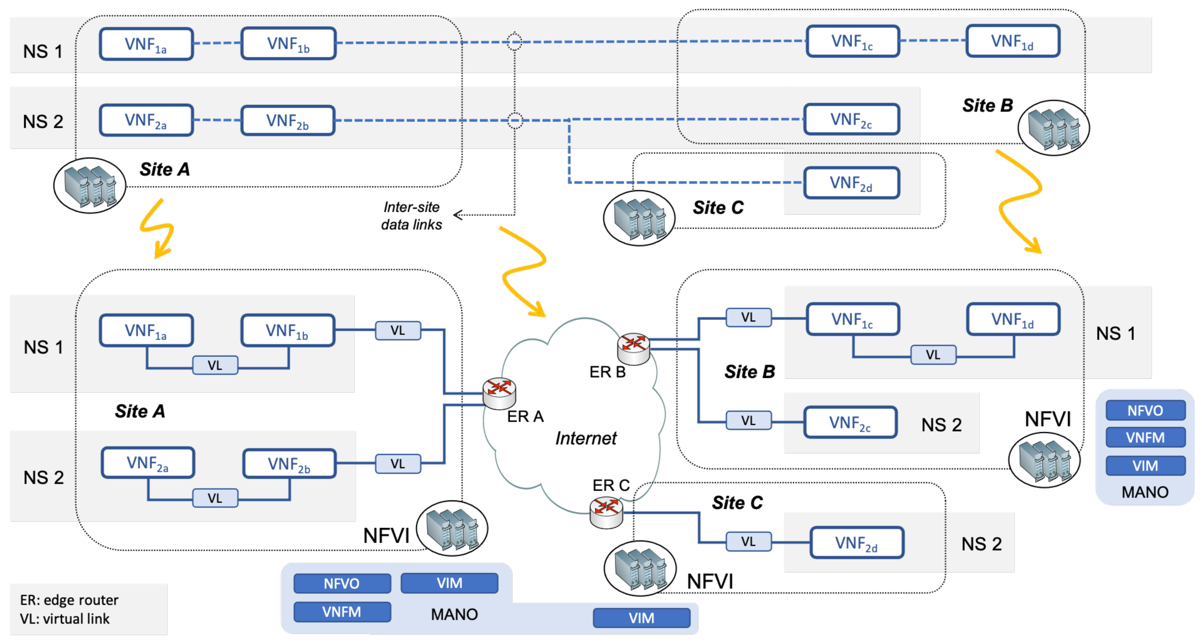
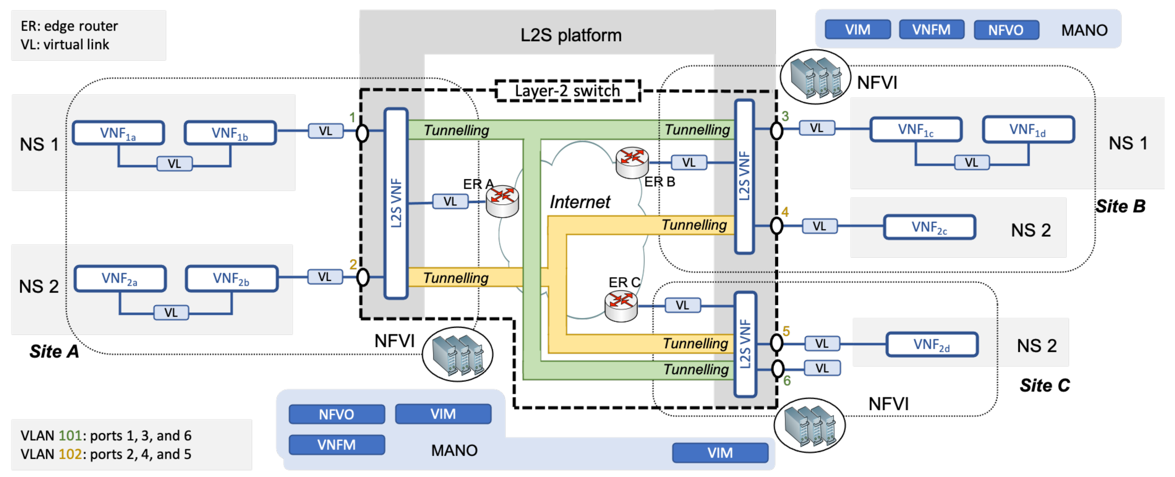
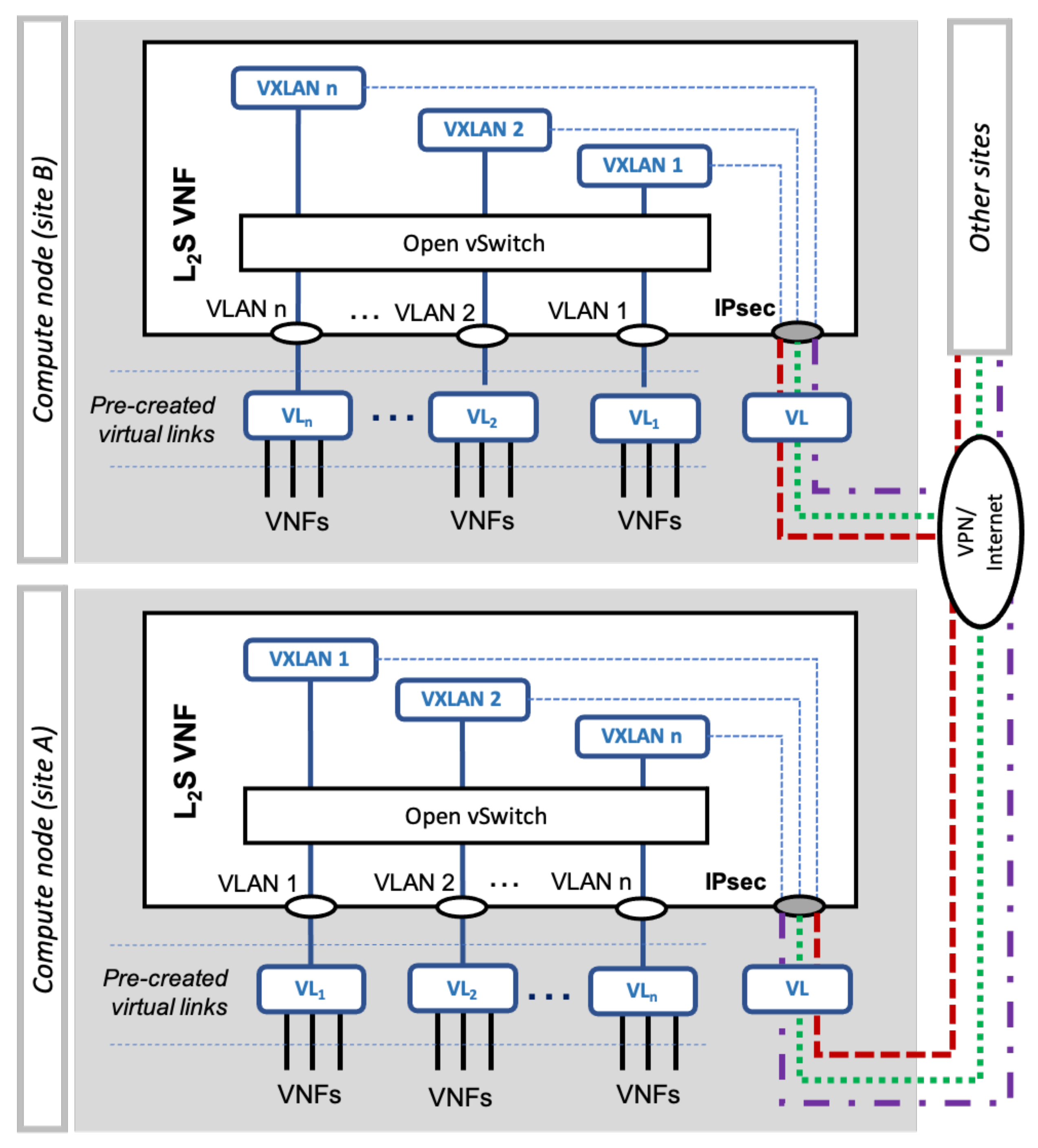
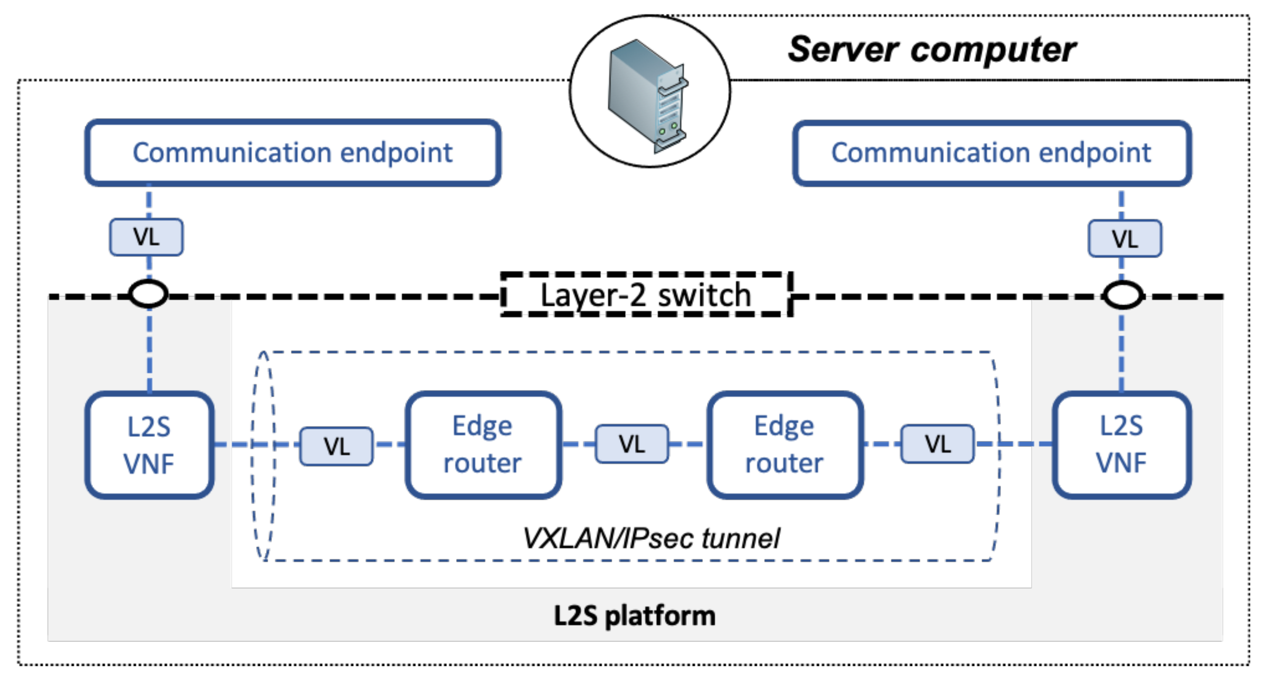
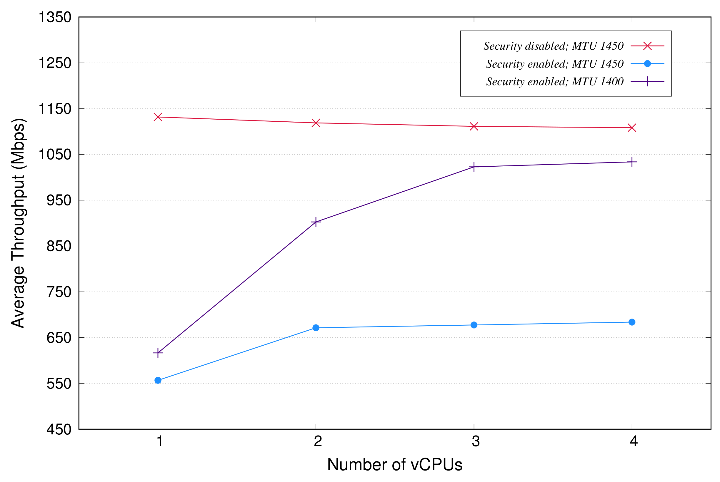
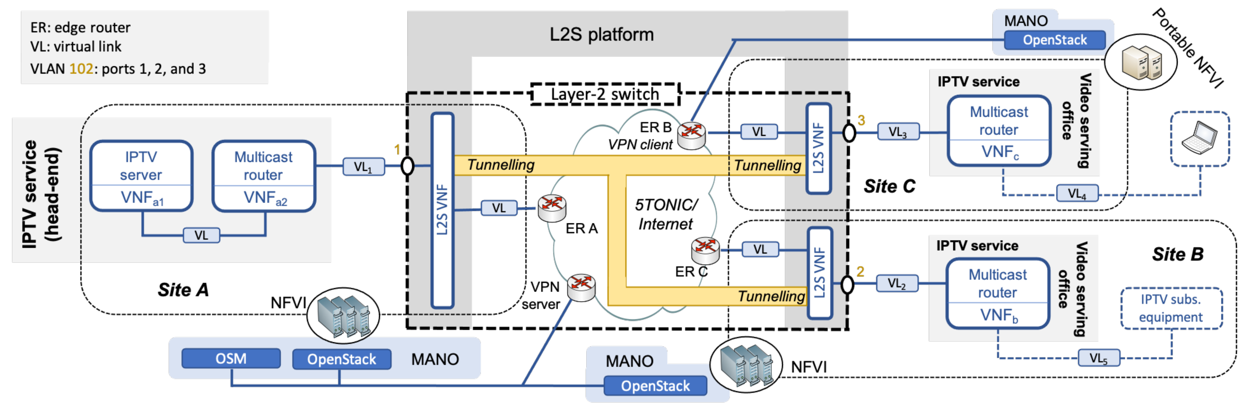
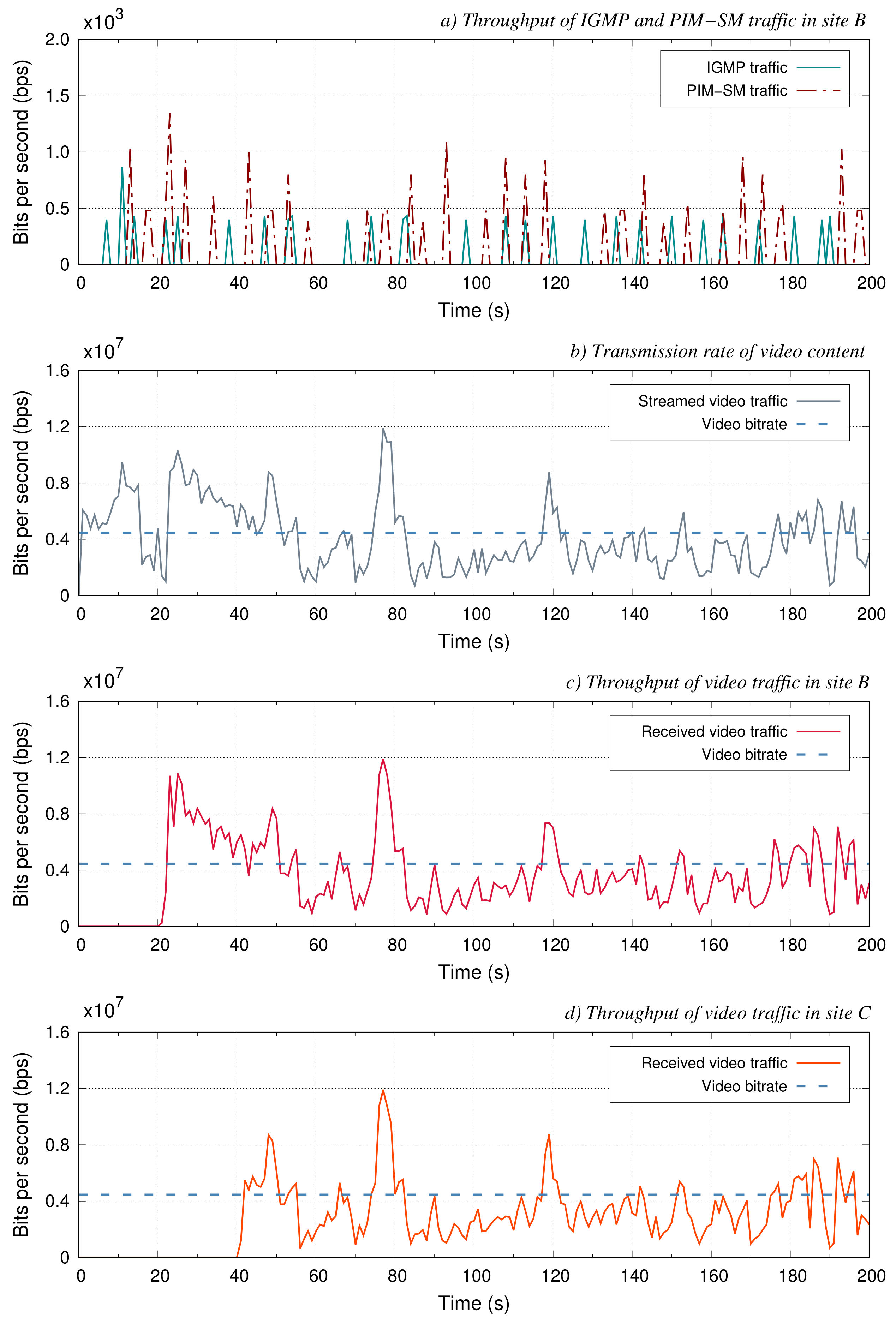
Table 1.
Parallelizable fraction of L2S operations.
| Scenario | p | Th(1) | Th(p) | f |
|---|---|---|---|---|
| IPsec, MTU 1400 | 2 | 616.50 Mb/s | 902.55 Mb/s | 0.634 |
| IPsec, MTU 1450 | 2 | 556.67 Mb/s | 671.50 Mb/s | 0.342 |
Publisher’s Note: MDPI stays neutral with regard to jurisdictional claims in published maps and institutional affiliations. |
© 2021 by the authors. Licensee MDPI, Basel, Switzerland. This article is an open access article distributed under the terms and conditions of the Creative Commons Attribution (CC BY) license (https://creativecommons.org/licenses/by/4.0/).
Share and Cite
MDPI and ACS Style
Vidal, I.; Nogales, B.; Lopez, D.; Rodríguez, J.; Valera, F.; Azcorra, A. A Secure Link-Layer Connectivity Platform for Multi-Site NFV Services. Electronics 2021, 10, 1868. https://0-doi-org.brum.beds.ac.uk/10.3390/electronics10151868
AMA Style
Vidal I, Nogales B, Lopez D, Rodríguez J, Valera F, Azcorra A. A Secure Link-Layer Connectivity Platform for Multi-Site NFV Services. Electronics. 2021; 10(15):1868. https://0-doi-org.brum.beds.ac.uk/10.3390/electronics10151868
Chicago/Turabian StyleVidal, Ivan, Borja Nogales, Diego Lopez, Juan Rodríguez, Francisco Valera, and Arturo Azcorra. 2021. "A Secure Link-Layer Connectivity Platform for Multi-Site NFV Services" Electronics 10, no. 15: 1868. https://0-doi-org.brum.beds.ac.uk/10.3390/electronics10151868
Note that from the first issue of 2016, this journal uses article numbers instead of page numbers. See further details here.