A Horn Antenna Covered with a 3D-Printed Metasurface for Gain Enhancement
by
 , ,
, ,
Sujan Shrestha
1,* ,
,
Affan A. Baba
1 ,
,
Syed Muzahir Abbas
1,2, 
Mohsen Asadnia
1 and
Raheel M. Hashmi
1 1
Faculty of Science and Engineering, School of Engineering, Macquarie University, Macquarie Park, NSW 2109, Australia
2
BENELEC, Botany, NSW 2019, Australia
*
Author to whom correspondence should be addressed.
Electronics 2021, 10(2), 119; https://0-doi-org.brum.beds.ac.uk/10.3390/electronics10020119
Submission received: 16 November 2020
/
Revised: 28 December 2020
/
Accepted: 5 January 2021
/
Published: 8 January 2021
(This article belongs to the Special Issue Innovative Antenna Technologies and Applications)
Abstract
:A simple metasurface integrated with horn antenna exhibiting wide bandwidth, covering full Ku-band using 3D printing is presented. It consists of a 3D-printed horn and a 3D-printed phase transformation surface placed at the horn aperture. Considering the non-uniform wavefront of 3D printed horn, the proposed 3D-printed phase transformation surface is configured by unit cells, consisting of a cube in the centre which is supported by perpendicular cylindrical rods from its sides. Placement of proposed surface helps to improve the field over the horn aperture, resulting in lower phase variations. Both simulated and measured results show good radiation characteristics with lower side lobe levels in both E- and H-planes. Additionally, there is an overall increment in directivity with peak measured directivity up to 24.8 dBi and improvement in aperture efficiency of about 35% to 72% in the frequency range from 10–18 GHz. The total weight of the proposed antenna is about 345.37 g, which is significantly light weight. Moreover, it is a low cost and raid manufacturing solution using 3D printing technology.
1. Introduction
Additive manufacturing technology, also known as three dimensional (3D) technique, has attracted attention recently because of its eco-friendliness, flexibility to realize complex structure, low power consuming, and low body mass, which are associated with economical benefits. Thus, because of its cost effectiveness, 3D printing is growing in popularity [1,2,3,4,5]. Particularly for complicated structures, where the methods of fabrication are difficult, 3D printing is expected to be promising method [6]. Furthermore, 3D printing is applied in fabricating various microwave components [7], transmit array structures [8,9], and lens antenna [10,11]. However, transmit array and lens antennas, which depend on the ratio of focal distance from source to diameter of aperture, are particularly larger in dimension. Additionally, many studies have been carried out to enhance the performance of Transmit array in terms of bandwidth, particularly by using multiple layers of superstrate as observed in [11,12], where transmission amplitude and phase are managed. Considering this aspect, to eliminate conductor loss caused by metallic patterns, the proposed 3D-printed structure is used to simplify the unit cell design and improve the directivity and aperture efficiency. In order to achieve high transmission bandwidth, a horn antenna is used and this has been traditionally manufactured by the computer numerical control method, which is costly and geometrically complicated. Moreover, the dielectric flat perforated lens is proposed in [13], which shows the improved directivity of conical horn antennas. Similarly, a wideband nature for horn antenna is studied in [14], where an ultrathin metasurface lens with wide flare angle is used. However, the proposed 3D-printed prototype has rapidly manufacturable 3D geometrical shape, is light in weight and has less flare angle. In microwave horn antenna manufacturing, there is a need for light weight, low cost, and high performance. Horn antenna is growing in popularity for the transmission and reception of electromagnetic wave particularly in conjunction with waveguide feed for radio astronomy, satellite tracking which is used in application at ultra-high and microwave frequency ranges [15]. Numerous studies have been carried in this arena to enhance the performance of feed horns, particularly with the use of 3D printing technology [16,17,18,19,20] and an interesting technique is the development of metamaterial, which shows desirable electromagnetic properties that are not easily observed in nature. For instance, the metamaterial-based method is applied to decrease the side lobe label of the rectangular horn antenna [21] by coating the interior E-plane walls with high surface impedance metasurfaces. Interestingly, square metal patch and ring are used to design multilayer non uniform metasurfaces [22] which shows high gain and beam controlling capability. Similarly, the metasurface lens designed with array of split ring resonator on FR4 [23] shows the improved radiation pattern at the main lobe. Additionally, to study the narrow band characteristic of resonant cavity antenna, 3D printing technology is used which improves the characteristic of feed antenna in terms of directivity, gain and side lobe level [24,25]. It is interesting to note whether the 3D-printed structure will be suitable to operate in the case of a wide band feed source. In order to further investigate these aspects, in this paper, we proposed the structure above the 3D-printed horn antenna which shows wide bandwidth in operation. We have investigated and studied the bandwidth behaviour of a 3D-printed prototype over the entire Ku-band. The novelty of the proposed transmit array is to improve the bandwidth with the use of 3D-printed structure. The proposed antenna system shows high gain, broad bandwidth, light weight and is inexpensive to manufacture, which eventually decreases the number of conductor layers. To validate the wideband nature of proposed antenna prototype, we have designed a 3D-printed horn, which is light in weight and low in cost compared to the standard Ku-band horn. Fused Deposition Modeling (FDM) is used for printing a horn with 100% infill ratio. Furthermore, the manufactured horn is copper plated along its internal and external surfaces. Similarly, the proposed structure above the feed horn is manufactured by the Multijet Printing (MJP) method which offers high design freedom and higher accuracy, and produces parts with good and consistent mechanical properties.
We have considered the aperture size of around 4 × 4 with 12 GHz as an operating frequency. This paper aims to enhance the bandwidth of source antenna which ultimately shows improved radiation directivity, realized gain and aperture efficiency. The remainder of the manuscript is presented in four sections. Consideration of unit cell and its placement in the respective aperture position is discussed in Section 2. Section 3 presents the transformed phase distribution for different frequencies at quarter wavelength distance above the structure. Furthermore, fabrication techniques along with comparison between measurement and simulation results of radiation characteristics are shown in Section 4. Finally, Section 5 presents the concluding remarks.
2. Analysis of Unit Cell
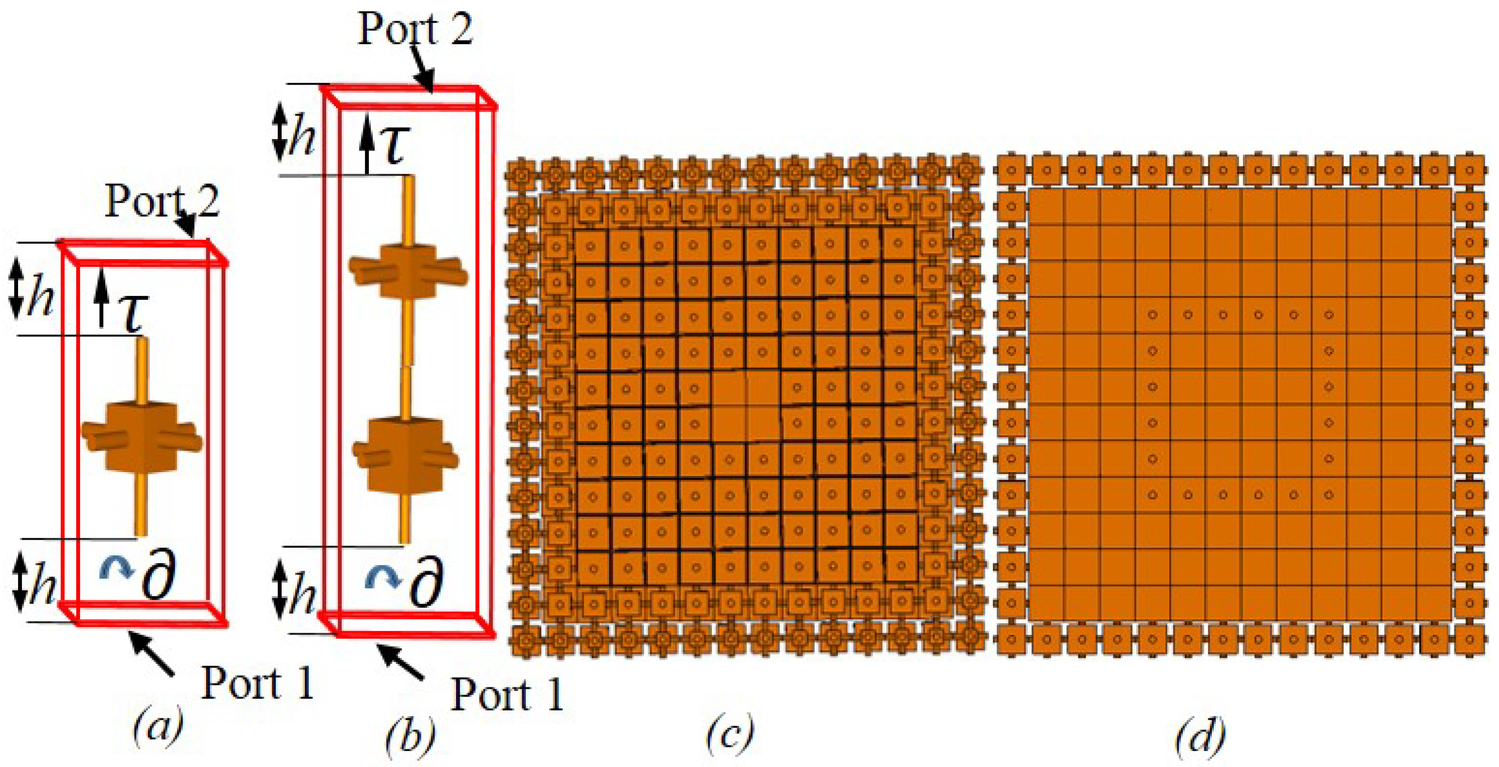
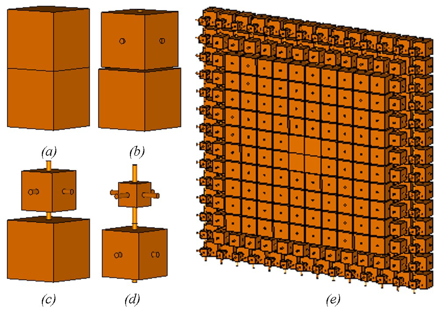
In order to support the performance of design concept, we have chosen a cube as a unit cell with permittivity of 2.8 and loss tangent value of 0.124. Three perpendicular cylindrical rods of length 7.5 mm (0.3) with diameter of 0.026 hold a cube whose size varies from 0.5 mm to 7.5 mm. We have considered 12 GHz as a design frequency. Variation of cube size is shown in Figure 1a,b, resulting in the change of transmission magnitude and phase. The single layer of cube size shows the phase variation of about 80° with transmission values () greater than 0.9. Similarly, the double layers of the cubes generate phase variation of about 160° whose transmission values () are more than 0.8. The database is generated based on the single and double layer of the cubes which is used for the placement of defined cube size in /2 and distance above the aperture of the horn feed. The standard rectangular horn has an aperture of mm × mm, so we have considered a 4 × 4 designed structure above the horn whose top and bottom views are also shown in Figure 1c,d, respectively. This figure depicts the relative cubes distribution throughout the aperture area. The cube sizes at the edge are relatively small due to the requirement of less phase variation as compared to the phase requirement across the center of the aperture.
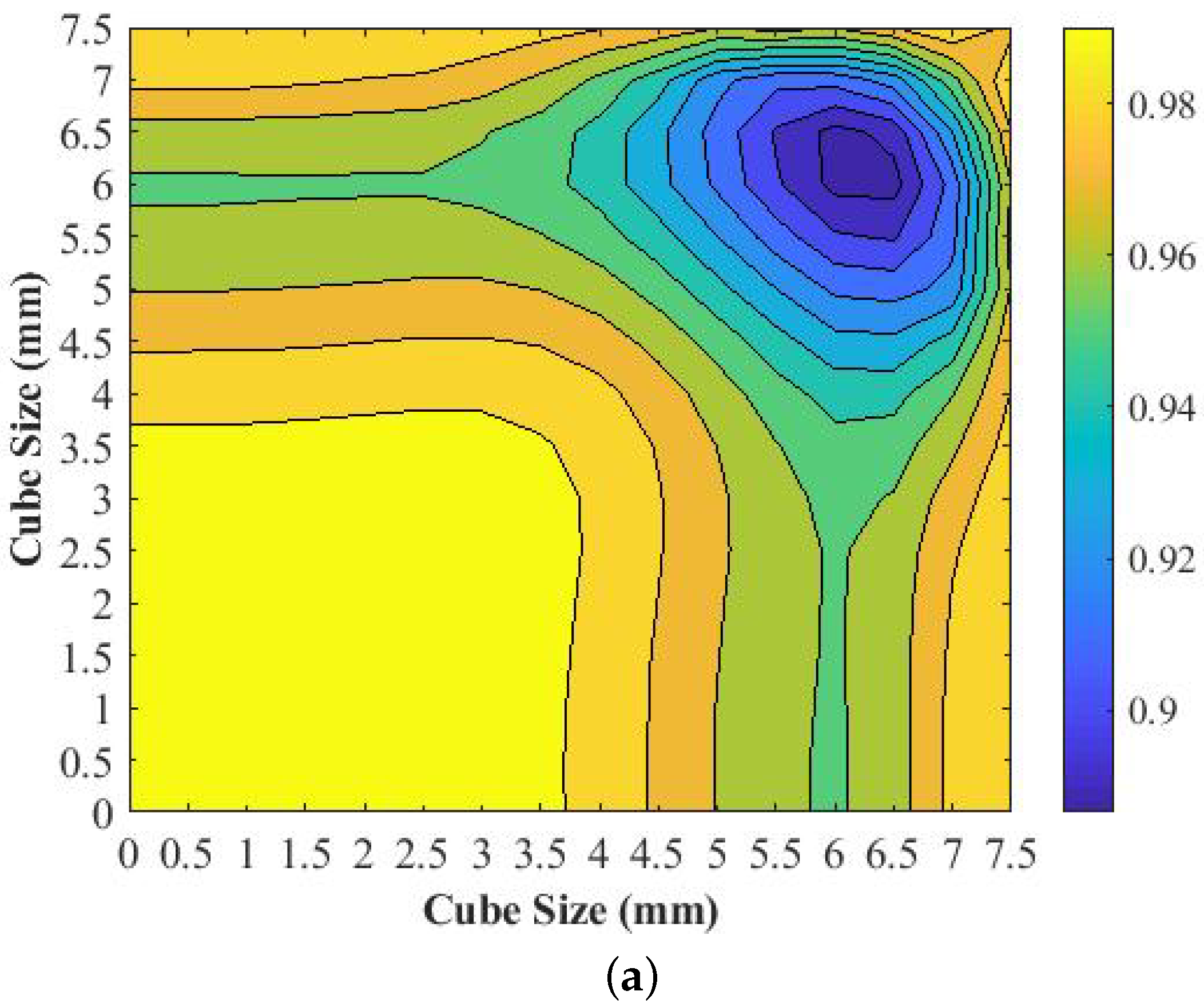
Figure 2a,b illustrate transmission magnitude and phase deviations against the cube size variations. As shown in Figure 2a, the transmission magnitude is more close to unity which is about 0.98 for cube sizes that are below 3.5 mm for both the top and bottom two layers of the cubes which decreases to 0.9 as the cube sizes approach their maximum values of 7.5 mm. Interestingly, the phase deviation as depicted in Figure 2b, is higher for cube sizes below 5 mm, which is about 160° to 140°. In contrast, these values are decreased to below 40° for higher cube sizes above 7 mm.
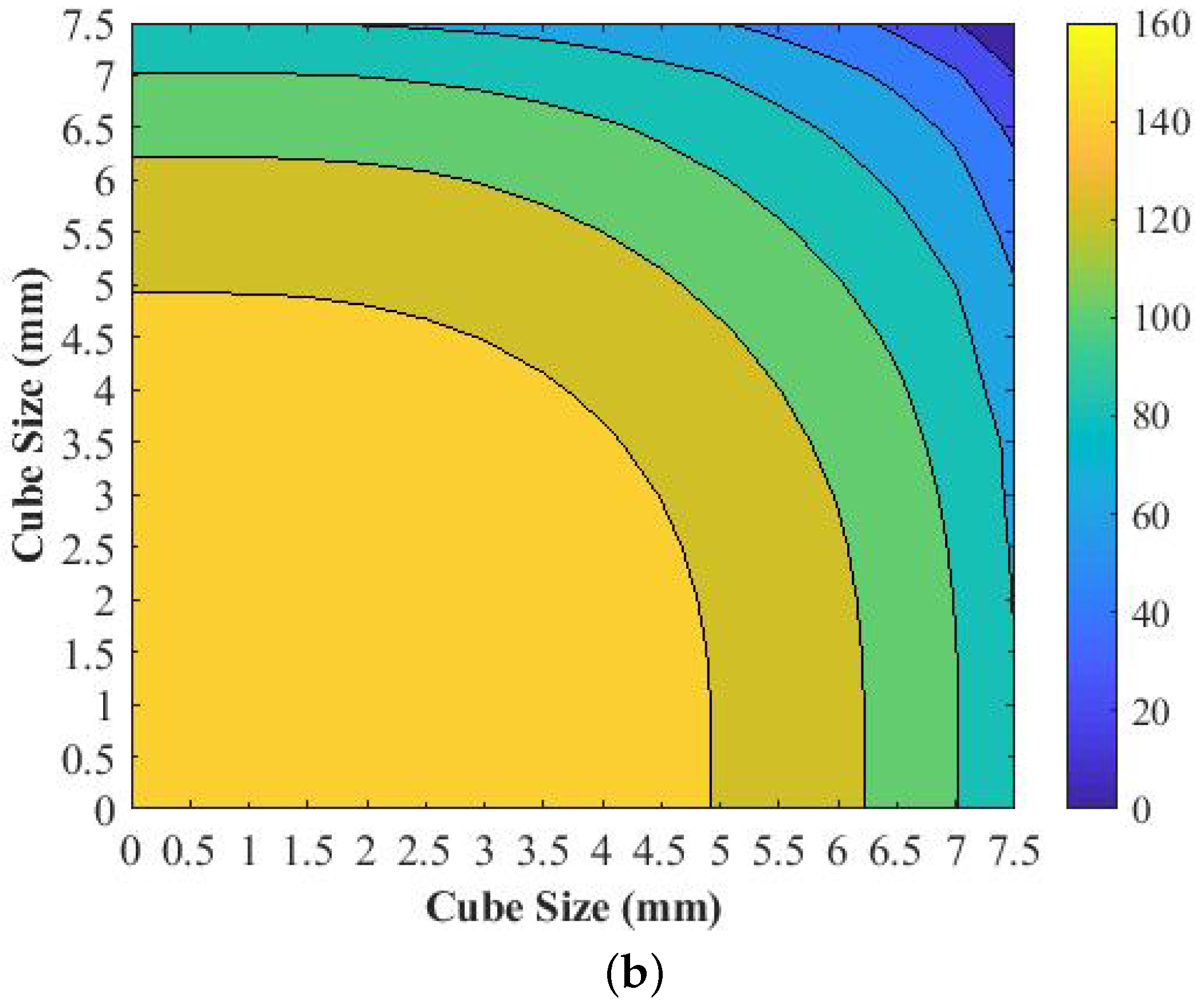
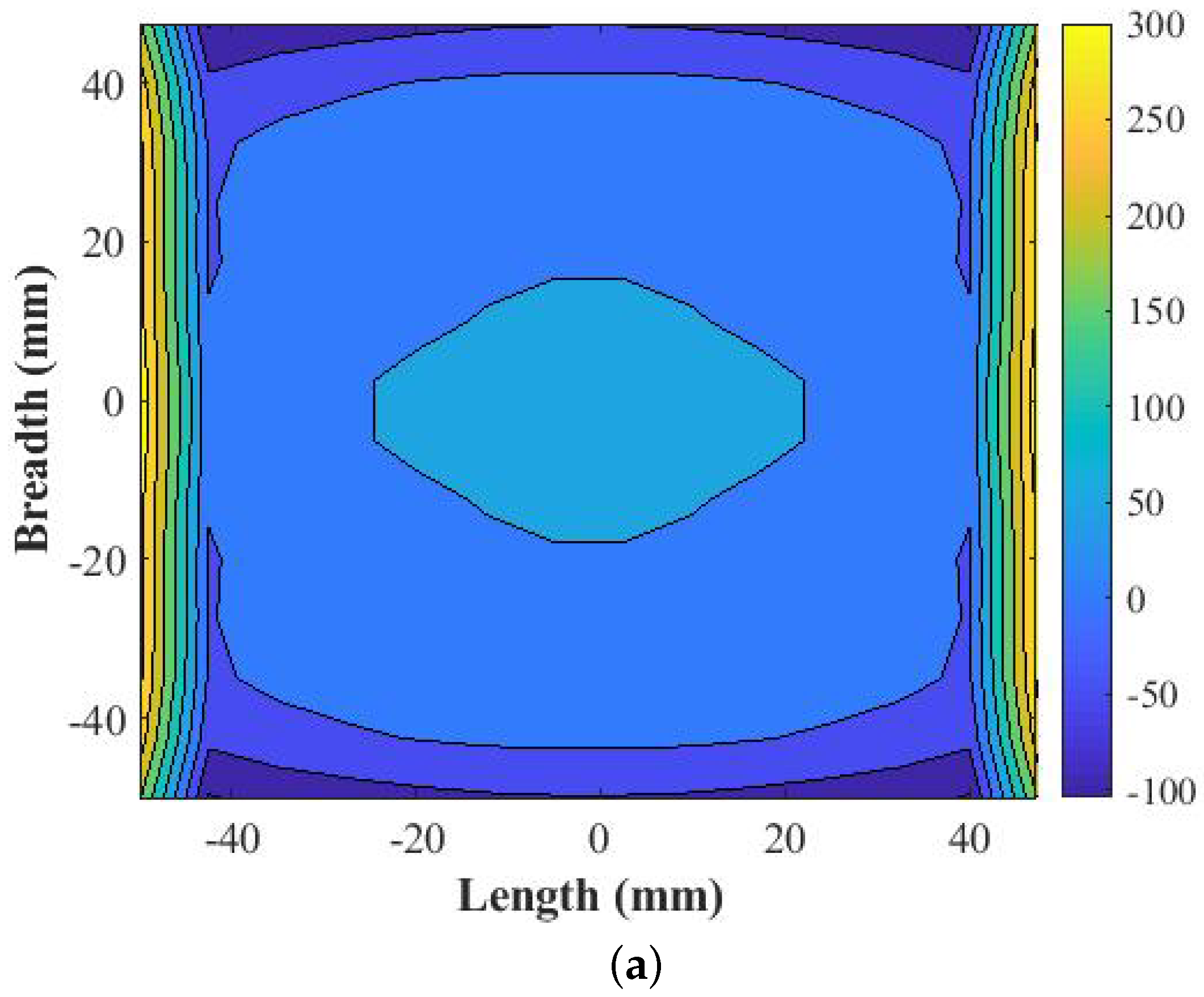
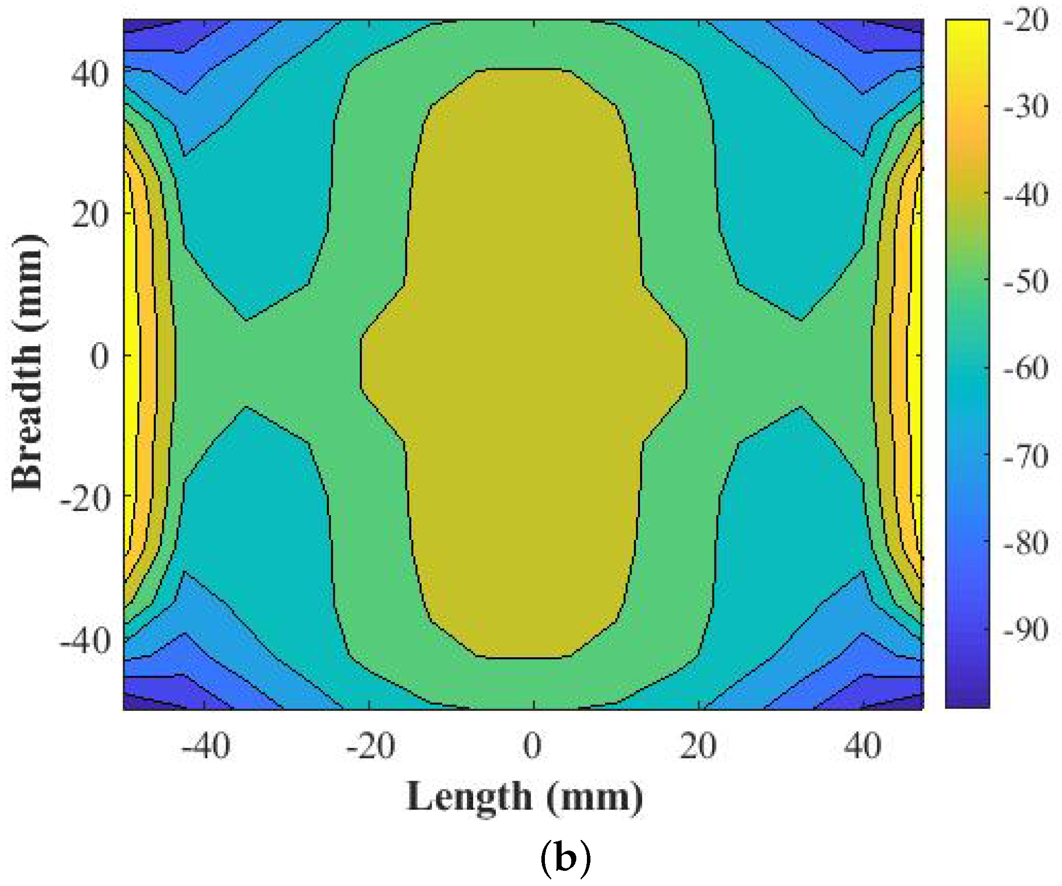
The phase distribution above the horn in /2 is shown in Figure 3a based upon which relative cube sizes are determined. As shown, the phase distribution towards the end of aperture is relatively high, about 300°. In contrast, the phase variation towards the center of the horn is less than 50°. In order to arrange two layer cubes distribution and to generated proposed 3D-printed structure, the aperture distance is maintained at 3.75 mm, 11.25 mm, 18.75 mm, 26.25 mm, 33.75 mm, 41.25 mm, and 48.75 mm from the center and the negative sign shows respective position in opposite direction. When the proposed 3D-printed structure is kept at /2 distance above the aperture of the horn, we have obtained the phase deviation as shown in Figure 3b. Thus, in those aperture positions based upon the phase variation, we have selected respectively two layers of cubes with maximum transmission magnitude values. Hence, the generated proposed 3D-printed structure of two layers of cubes has sufficiently corrected the phase to below 40°.
The synthesized unit cell sizes for cube size inside each unit cell is shown in Figure 4a–d. The identical four two-layer cubes, where the upper and lower cubes are of 7.5 mm in dimension, are placed at a distance of 3.75 mm along the aperture, as shown in Figure 4a. The required phase deviation is less in the center which requires cubes of higher sizes, as noted from the generated database of transmission magnitude and phase values. Similarly, the identical two layers of cubes where the upper and lower cubes are of 7 mm and 7.5 mm respectively, placed at 11.25 mm, 18.75 mm, 26.25 mm, and 33.75 mm from the center of aperture are highlighted in Figure 4b. There are 192 quantities. As the phase variation is relatively high towards the end of the aperture, the cube sizes start decreasing. Along the aperture, at 41.25 mm from the center, the two layers of cubes where the upper and lower layers have cubes of dimension 5 mm and 7.5 mm respectively are shown in Figure 4c that have 88 quantities. Finally, at the end of the aperture, 48.75 mm from the center, where the phase requirement is relatively high, the cube sizes in the two layers of cube distribution are observed to be smaller in dimension, namely 3 mm and 6 mm, respectively, along the upper and lower layers, as depicted in Figure 4d. They have 104 quantities. The overall structure of the array with its perspective view is depicted in Figure 4e. We have chosen the correct size of each cube from the database maintained from the variation of each cube values of two layers with the analysis performed in a two port network. The adopted synthesis of algorithms to determine the correct size of each cube are shown in the steps below.
Step 1: Determine the phase distribution in /2 distance from the horn aperture.
Step 2: Note the phase value from the center of the aperture at 3.75 mm, 11.25 mm, 18.75 mm, 26.25 mm, 33.75 mm, 41.25 mm, and 48.75 mm. Normalize the noted phase values.
Step 3: Check from the database the required phase value and pick the corresponding cube sizes that maintain the higher transmission magnitude.
Step 4: Place the respective cubes at 3.75 mm, 11.25 mm, 18.75 mm, 26.25 mm, 33.75 mm, 41.25 mm, and 48.75 mm from the center of the aperture for each round.
Thus, the 3D-printed transmits array structure is generated.
3. Phase Transformation
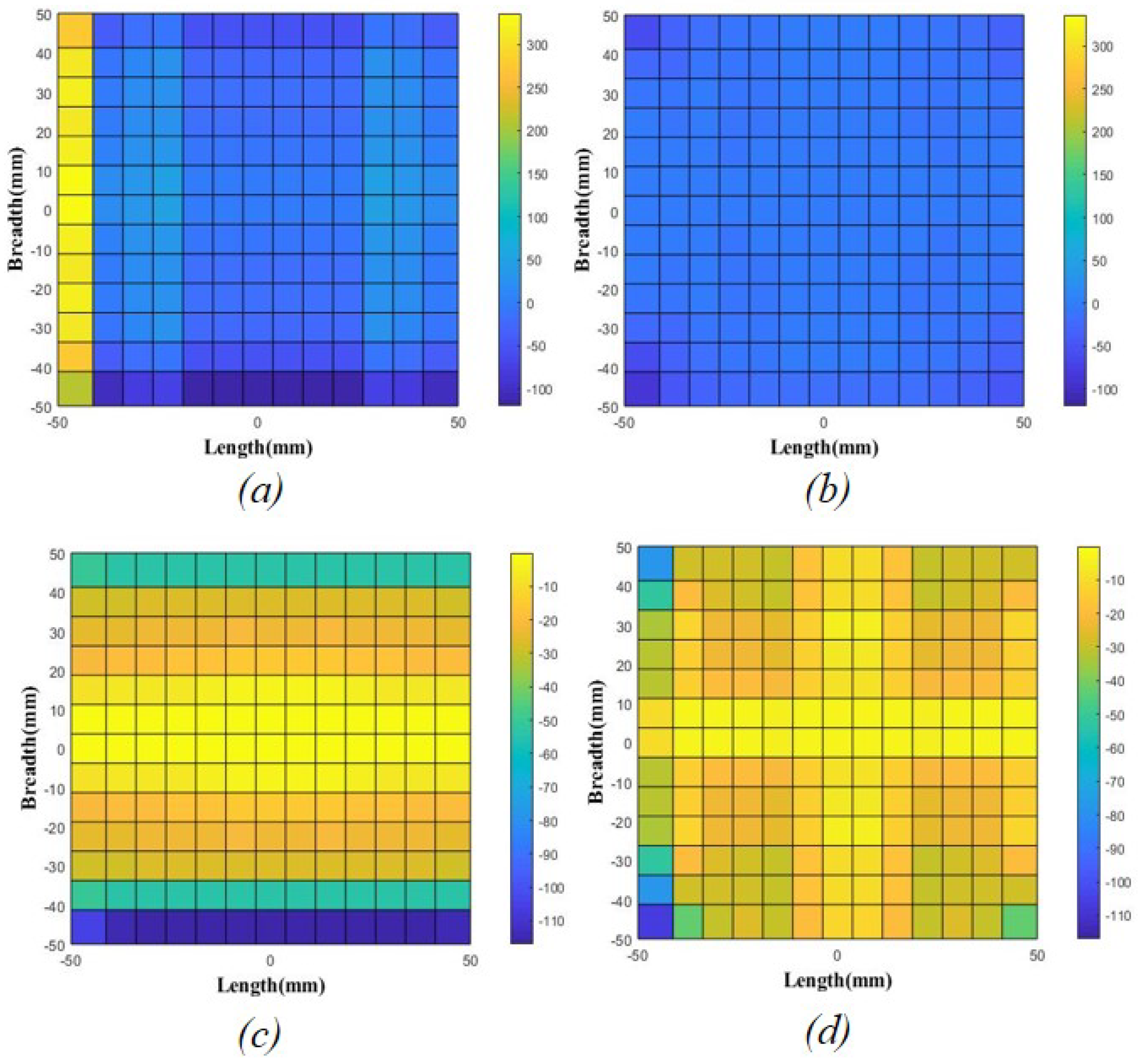
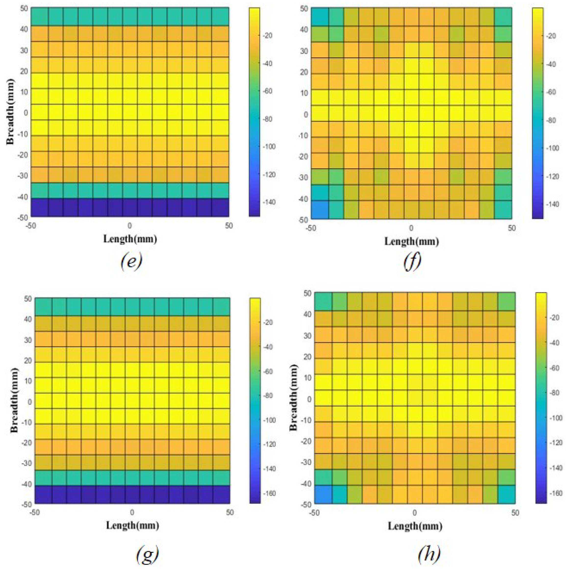
It is interesting to note the transformed phase variation above the designed structure as it is kept above the horn feed. We have considered phase variation along the E-plane where the variation in phase of 161.41°, 160.99°, 204.28°, 232.31° are noted only for horn feed in 12, 13, 15 and 17.5 GHz respectively, which are decreased to 30.22°, 18.69°, 39.59°, 29.96° after the placement of the designed structure, as shown in Figure 5.
4. Fabrication and Measurement Results
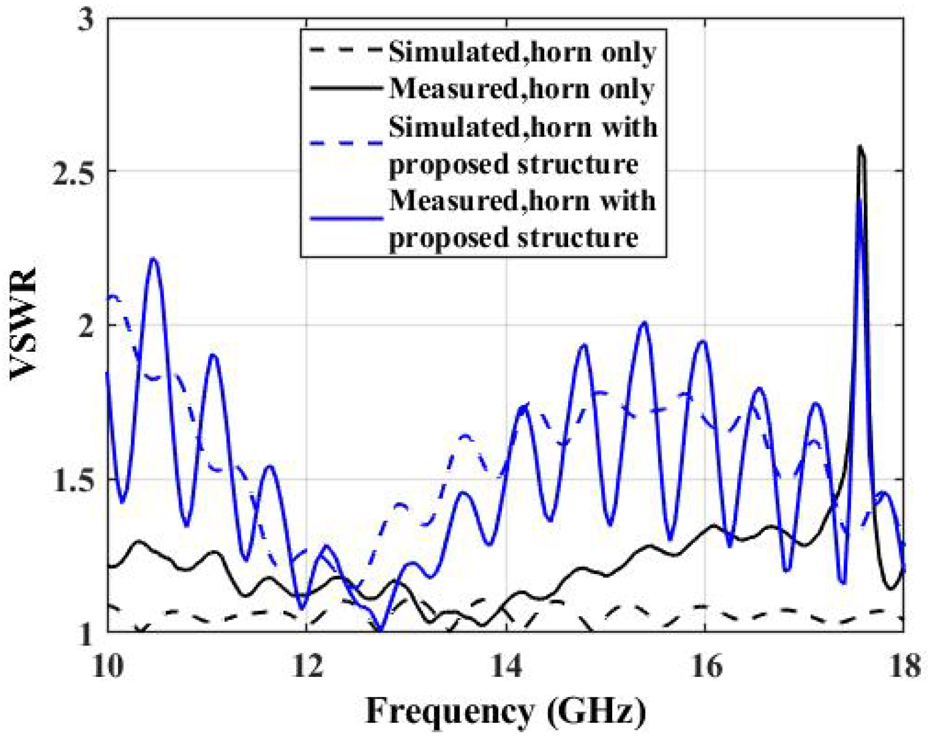
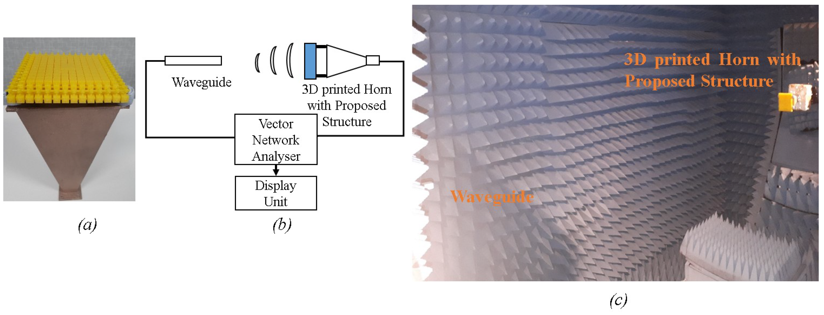
For the validation of the proposed concept, we have fabricated the structure with MJP method from Stratasys J750 3D printer which prints the part that features Digital ABS Plus. This material shows a dielectric constant, of about 2.8 and loss tangent of about 0.124, as tested from dielectric probe and Nicolson-Ross-Weir (NRW) methods. Similarly, Acrylonitrile Butadiene Styrene (ABS) is used for 3D printing of the horn part from an Omni3D printer with 100% infill value which is later copper plated in the inside and outside layers. We have used a WR-75 waveguide feed horn as a feeding source below the proposed prototype. The fabricated 3D-printed horn and proposed prototype possesses compact size with light weight of about 121 g and 140 g respectively. This makes the total antenna weight of about 345.37 g including the weight of WR-75 waveguide, which is 84.37 g. This shows that the 3D-printed horn weight is far less then WR-75 Standard Gain Horn, which weighs 1.81 kg. Figure 6 shows the matching of the antenna prototype where voltage standing wave ratio (VSWR), measured using HP8720D vector network analyzer for the 3D-printed horn, is below 1.25 except in the case of higher frequencies above 17.5 GHz. Similarly, the simulated and measured horn with proposed structure indicates VSWR which is below 2, except in the case of higher frequencies above 17.5 GHz. This is due to the limitation in aperture dimension of the horn as well as the feed waveguide operational frequency boundary [26]. The matching is shown in the VSWR plot in Figure 6, where the transmit array feed by horn achieves good matching which is obtained by maintaining the suitable distance from feed source to the transmit array elements. The whole 3D-printed structure is obtained by the arrangement of two layers of cubes that act as a unit cell, where the matching is maintained by tuning the distance from the horn aperture. Furthermore, Figure 7 shows the fabricated prototype and measurement setup in NSI-700S-50 spherical near the field measurement system at the Australian Antenna Measurement Facility. The measurement results thus obtained are compared to the computed values. We have performed full-wave simulations that were carried out by using commercial software CST Microwave studio.
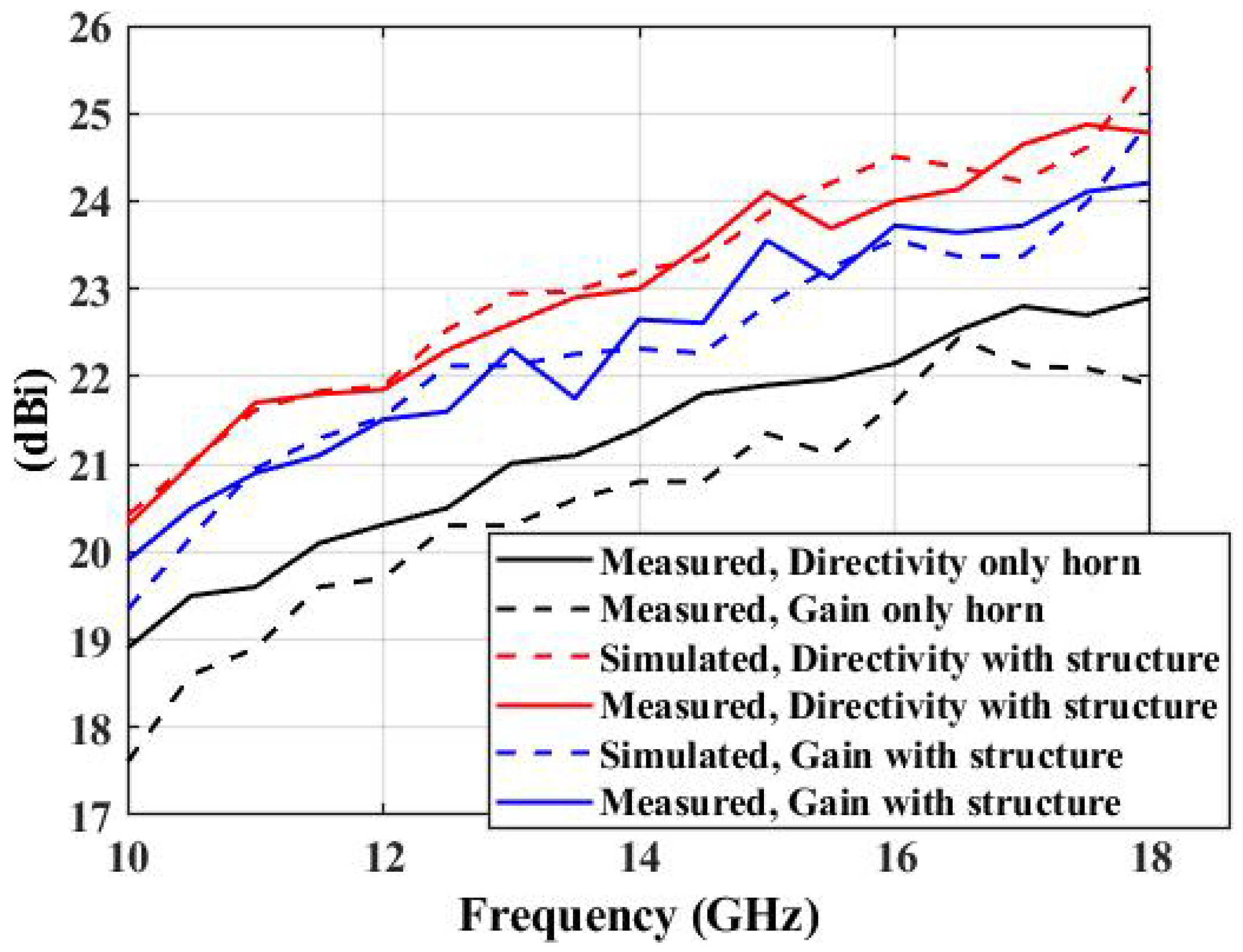
Similarly, simulated and measured directivity and gain with and without the antenna prototype above the feed horn is shown in Figure 8. This figure revealed that the proposed prototype shows better directivity and gain from 10 to 18 GHz with some slight deviation towards the higher frequency range, particularly above 17.5 GHz. This deviation might resulted from the higher cross polarization values above 17.5 GHz. A similar pattern is observed without the proposed prototype above the 3D-printed horn where directivity and gain trends are quite well matched.
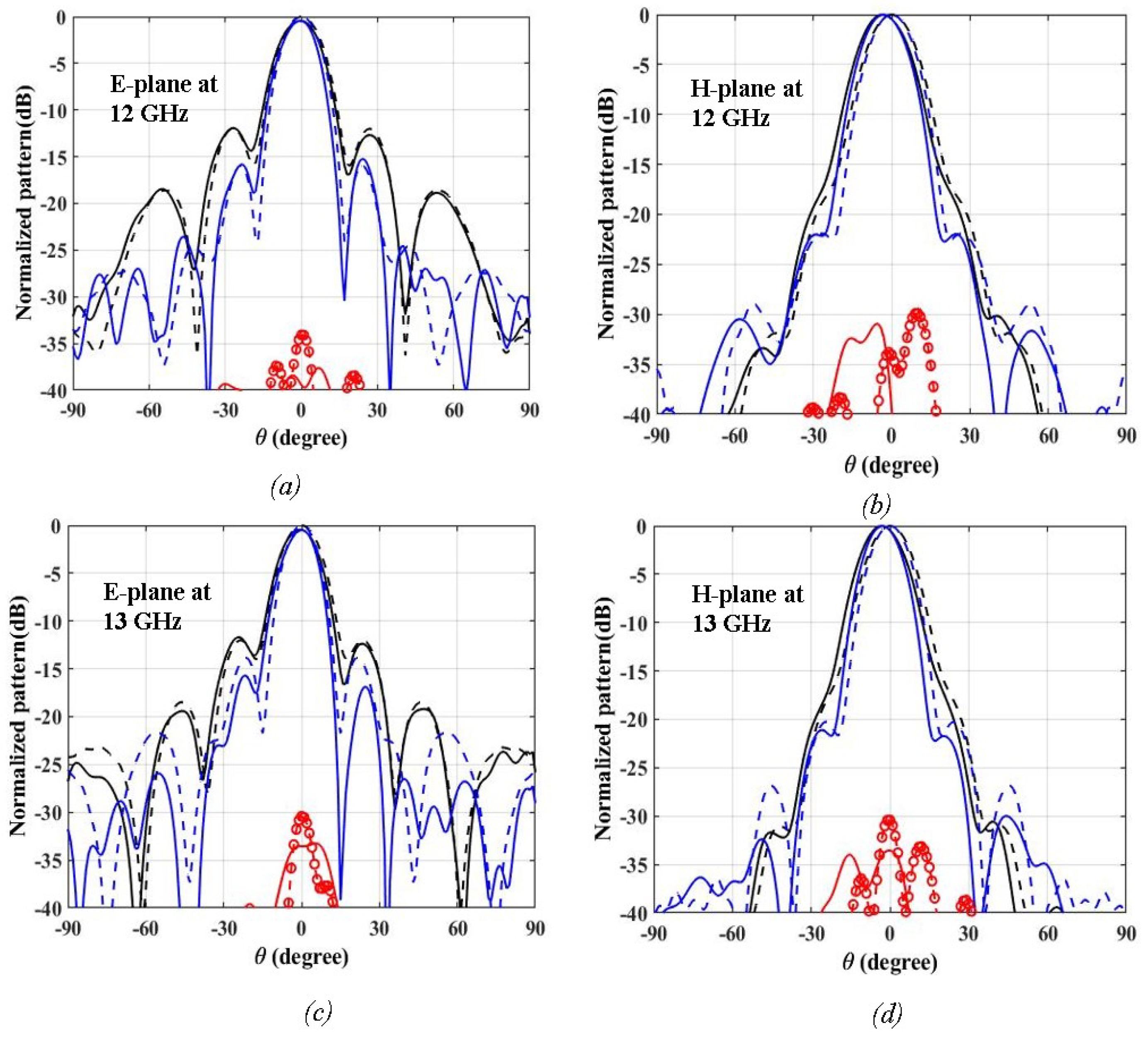
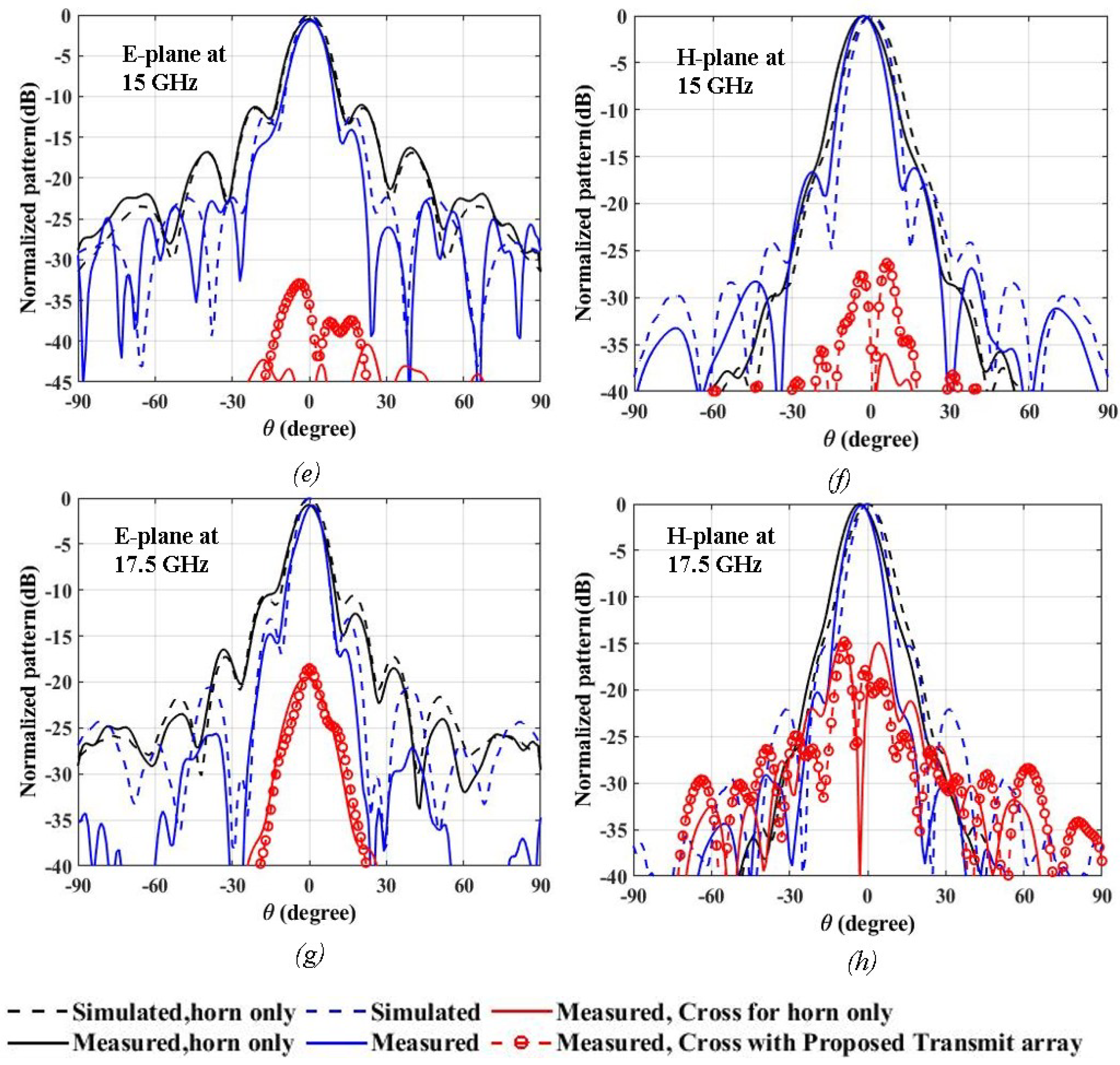
The measured and computed normalized radiation patterns along with cross polarization values are depicted in Figure 9a–h. Simulated and measured radiation patterns are well matched as depicted in Figure 9a–f for 12, 13 and 15 GHz respectively with lower cross polarization values below −25 dB for E- and H-planes. Particularly, distortion in radiation patterns are observed from 17.5 GHz where the cross polarization values started to be higher which is about −15 dB, as shown in Figure 9g,h. This indicates the capability of proposed prototype antenna for wideband operation, particularly from 10 to 15 GHz with some distortion for higher frequencies above 15 GHz. As the proposed prototype is kept above the feed horn source, the first side lobe level along E- plane is about 3 dB less than the E-plane of the horn source only. The horn source only shows a first side lobe level of about −11.98, −12.02, −11.42, −10.59 dB as compared to the −15.94, −13.84, −12.08, and −13.11 dB, which are obtained after placement of proposed prototype in 12, 13, 15, and 17.5 GHz respectively.
Interestingly, Table 1 depicts the improved realized Gain (G), aperture efficiency (Ae) and Side lobe level (SLL) with improved bandwidth of the proposed prototype as compared to previously proposed horn antennas. As noticed, from 10 GHz to 18 GHz, the realized gain of the antenna is improved to about 19.9 to 24.8 dBi with aperture efficiency in the range from 95% to 142% along with side lobe level from −16 to −40 dB. Similarly, bandwidth is comparatively higher at 66.67%.
5. Conclusions
In conclusion, we have presented a lightweight and enhanced antenna prototype that could be applied for wideband operations. The multijet printing process is used to fabricate the proposed prototype by using casting wax materials layer by layer. This proposed structure consisting of a 3D-printed horn and 3D-printed phase transformation surface exhibits improved radiation characteristics, in particular directivity, realized gain, and aperture efficiency, throughout the operational frequency bands and lower side lobe levels. The measured results validated the simulated trends, confirming the wideband operation of the proposed prototype. Moreover, it is significantly light weight (345.37 g) and can be made using radip 3D printing technology for use in communication systems where there is the need for wide bandwidth with reasonable high gain.
Author Contributions
All authors equally contributed for developing methodology, performance analysis and drafting the manuscript. All authors have read and agreed to the published version of the manuscript.
Funding
This work was supported in part by the Australian Research Council (ARC) and in part by the Macquarie University International Research Excellence Scholarship (iMQRES).
Acknowledgments
We want to extend thankfulness to CSIRO, Marsfield, NSW, Australia and Macquarie University for providing support for measurement of antenna prototype.
Conflicts of Interest
The authors declare no conflict of interest.
References
- Honari, M.M.; Mirzavand, R.; Aslanzadeh, S.; Saghlatoon, H.; Mousavi, P. Wideband Printed TM 01 to TE 11 Mode Converters. IEEE Access 2019, 7, 35438–35448. [Google Scholar] [CrossRef]
- Alkaraki, S.; Andy, A.S.; Gao, Y.; Tong, K.F.; Ying, Z.; Donnan, R.; Parini, C. Compact and Low-Cost 3-D Printed Antennas Metalized Using Spray-Coating Technology for 5G mm-Wave Communication Systems. IEEE Antennas Wirel. Propag. Lett. 2018, 17, 2051–2055. [Google Scholar] [CrossRef]
- Liang, M.; Ng, W.R.; Chang, K.; Gbele, K.; Gehm, M.E.; Xin, H. A 3-D Luneburg lens antenna fabricated by polymer jetting rapid prototyping. IEEE Trans. Antennas Propag. 2014, 62, 1799–1807. [Google Scholar] [CrossRef]
- Chieh, J.C.S.; Dick, B.; Loui, S.; Rockway, J.D. Development of a Ku-band corrugated conical horn using 3-D print technology. IEEE Antennas Wirel. Propag. Lett. 2014, 13, 201–204. [Google Scholar] [CrossRef]
- Du, G.; Liang, M.; Sabory-Garcia, R.A.; Liu, C.; Xin, H. 3-D printing implementation of an X-band Eaton lens for beam deflection. IEEE Antennas Wirel. Propag. Lett. 2016, 15, 1487–1490. [Google Scholar] [CrossRef]
- Ghazali, M.I.M.; Karuppuswami, S.; Kaur, A.; Chahal, P. 3-D printed air substrates for the design and fabrication of RF components. IEEE Trans. Compon. Packag. Manuf. Technol. 2017, 7, 982–989. [Google Scholar] [CrossRef]
- Laplanche, E.; Feuray, W.; Sence, J.; Perigaud, A.; Tantot, O.; Delhote, N.; Menudier, C.; Arnaud, E.; Thevenot, M.; Monédière, T.; et al. Additive manufacturing of low cost and efficient proof of concepts for microwave passive components. IET Microw. Antennas Propag. 2017, 11, 1997–2004. [Google Scholar] [CrossRef]
- Massaccesi, A.; Pirinoli, P.; Bertana, V.; Scordo, G.; Marasso, S.L.; Cocuzza, M.; Dassano, G. 3D-printable dielectric transmitarray with enhanced bandwidth at millimeter-waves. IEEE Access 2018, 6, 46407–46418. [Google Scholar] [CrossRef]
- Matos, S.A.; Teixeira, J.P.; Costa, J.R.; Fernandes, C.A.; Nachabe, N.; Luxey, C.; Titz, D.; Gianesello, F.; Del Rio, C.; Arboleya, A.; et al. 3D-Printed transmit-array antenna for broadband backhaul 5G links at V band. IEEE Antennas Wirel. Propag. Lett. 2020, 19, 977–981. [Google Scholar] [CrossRef]
- Saghlatoon, H.; Honari, M.M.; Aslanzadeh, S.; Mirzavand, R. Electrically-small Luneburg lens for antenna gain enhancement using new 3D printing filling technique. AEU Int. J. Electron. Commun. 2020, 124, 153352. [Google Scholar] [CrossRef]
- Zhang, B.; Guo, Y.X.; Guo, Q.; Wu, L.; Ng, K.B.; Wong, H.; Zhou, Y.; Huang, K. Dielectric and metallic jointly 3D-printed mmWave hyperbolic lens antenna. IET Microw. Antennas Propag. 2019, 13, 1934–1939. [Google Scholar] [CrossRef]
- Ryan, C.G.M.; Chaharmir, M.; Shaker, J.; Bray, J.; Antar, Y.; Ittipiboon, A. A wideband transmitarray using dual-resonant double square rings. IEEE Trans. Antennas Propag. 2010, 58, 1486–1493. [Google Scholar] [CrossRef]
- Al-Nuaimi, M.K.T.; Hong, W.; Zhang, Y. Design of High-Directivity Compact-Size Conical Horn Lens Antenna. IEEE Antennas Wirel. Propag. Lett. 2014, 13, 467–470. [Google Scholar] [CrossRef]
- Liu, K.; Ge, Y.; Lin, C. A Compact Wideband High-Gain Metasurface-Lens-Corrected Conical Horn Antenna. IEEE Antennas Wirel. Propag. Lett. 2019, 18, 457–461. [Google Scholar] [CrossRef]
- Constantine, A. Balanis: Antenna Theory and Design; John Wileys & Sons: Hoboken, NJ, USA, 2005. [Google Scholar]
- Molaei, A.; Bisulco, A.; Tirado, L.; Zhu, A.; Cachay, D.; Dagheyan, A.G.; Martinez-Lorenzo, J. 3D-Printed e-Band compressive horn antenna for high-sensing-capacity imaging applications. IEEE Antennas Wirel. Propag. Lett. 2018, 17, 1639–1642. [Google Scholar] [CrossRef]
- Addamo, G.; Peverini, O.A.; Calignano, F.; Manfredi, D.; Paonessa, F.; Virone, G.; Dassano, G. 3D printing of high-performance feed horns from ku-to v-Bands. IEEE Antennas Wirel. Propag. Lett. 2018, 17, 2036–2040. [Google Scholar] [CrossRef]
- Zhang, S.; Cadman, D.; Vardaxoglou, J.Y.C. Additively manufactured profiled conical horn antenna with dielectric loading. IEEE Antennas Wirel. Propag. Lett. 2018, 17, 2128–2132. [Google Scholar] [CrossRef] [Green Version]
- Carkaci, M.E.; Secmen, M. The prototype of a wideband ku-band conical corrugated horn antenna with 3-D printing technology. Adv. Electromagn. 2019, 8, 39–47. [Google Scholar] [CrossRef]
- Chuma, E.L.; Iano, Y.; Roger, L.L.B.; Scroccaro, M.; Frazatto, F.; Manera, L.T. Performance analysis of x band horn antennas using additive manufacturing method coated with different techniques. J. Microw. Optoelectron. Electromagn. Appl. 2019, 18, 263–269. [Google Scholar] [CrossRef]
- Moradi, A.; Mohajeri, F. Side lobe level reduction and gain enhancement of a pyramidal horn antenna in the presence of metasurfaces. IET Microwaves Antennas Propag. 2017, 12, 295–301. [Google Scholar] [CrossRef]
- Han, J.; Li, L.; Zhang, T.; Xi, R. Control and improvement of antenna gain by using multilayer non-uniform metasurfaces. EPJ Appl. Metamater. 2019, 6, 4. [Google Scholar] [CrossRef]
- Manikandan, R.; Rao, P.; Jawahar, P. Gain enhancement of horn antenna using meta surface lens. Adv. Electromagn. 2018, 7, 27–33. [Google Scholar] [CrossRef]
- Yu, Y.H.; Wu, W.; Zong, Z.Y.; Fang, D.G. Awire-metamaterial-loaded resonant cavity antenna using 3D printing technology. IEEE Antennas Wirel. Propag. Lett. 2018, 17, 2119–2122. [Google Scholar] [CrossRef]
- Hayat, T.; Afzal, M.U.; Lalbakhsh, A.; Esselle, K.P. 3D printed phase-rectifying transparent superstrate for resonant-cavity antenna. IEEE Antennas Wirel. Propag. Lett. 2019, 18, 1400–1404. [Google Scholar] [CrossRef]
- Baba, A.A.; Hashmi, R.M.; Esselle, K.P.; Weily, A.R. Compact high-gain antenna with simple all-dielectric partially reflecting surface. IEEE Trans. Antennas Propag. 2018, 66, 4343–4348. [Google Scholar] [CrossRef]
Figure 1.
(a) One layer cube arrangement (b) Two layer cube arrangement (c) Top view (d) Bottom view of the designed structure.
Figure 1.
(a) One layer cube arrangement (b) Two layer cube arrangement (c) Top view (d) Bottom view of the designed structure.

Figure 2.
Variation of (a) Transmission Magnitude distribution against cube sizes (b) Transmission Phase deviation against cube sizes.
Figure 2.
Variation of (a) Transmission Magnitude distribution against cube sizes (b) Transmission Phase deviation against cube sizes.


Figure 3.
(a) Phase distribution without Proposed Transmit array structure of only horn feed. (b) Phase distribution above Proposed Transmit array structure.
Figure 3.
(a) Phase distribution without Proposed Transmit array structure of only horn feed. (b) Phase distribution above Proposed Transmit array structure.


Figure 4.
(a) Unit Cell in center of aperture (b) Unit Cell in 11.25 mm, 18.75 mm, 26.25 mm and 33.75 mm from the center of the aperture (c) Unit Cell in 41.25 mm from the center of the aperture (d) Unit Cell in 48.75 mm from the center of the aperture (e) Prospective view of the proposed transmit array designed structure.

Figure 5.
Near field phase distribution (a,c,e,g) 3D-printed Horn antenna (b,d,f,h) Variation in phase after the placement of proposed structure at 12, 13, 15, and 17.5 GHz respectively.
Figure 5.
Near field phase distribution (a,c,e,g) 3D-printed Horn antenna (b,d,f,h) Variation in phase after the placement of proposed structure at 12, 13, 15, and 17.5 GHz respectively.


Figure 6.
Simulated and measured voltage standing wave ratio (VSWR) of the horn and prototype antenna.
Figure 6.
Simulated and measured voltage standing wave ratio (VSWR) of the horn and prototype antenna.

Figure 7.
Fabricated and measurement set up (a) Fabricated prototype kept above 3D-printed horn source (b) Measurement set up of proposed antenna prototype. (c) Testing setup performed in measurement chamber.
Figure 7.
Fabricated and measurement set up (a) Fabricated prototype kept above 3D-printed horn source (b) Measurement set up of proposed antenna prototype. (c) Testing setup performed in measurement chamber.

Figure 8.
Simulated and measured directivity and gain without and with antenna prototype.

Figure 9.
Figures (a–h) shows measured and simulated radiation patterns in 12, 13, 15 and 17.5 GHz respectively.
Figure 9.
Figures (a–h) shows measured and simulated radiation patterns in 12, 13, 15 and 17.5 GHz respectively.


Table 1.
Comparison of proposed antenna against the available antenna prototypes.
| References | Dimension (mm × mm × mm) | Peak Gain (dBi) | Operating Frequency Range (GHz) | Aperture Efficiency (%) | Bandwidth (%) | Range of Gain (dBi) | Side Lobe Level (dBi) | Weight (gm) | Fabrication Type |
|---|---|---|---|---|---|---|---|---|---|
| Proposed | 100 × 100 × 252.5 (4 × 4 × 10.1) | 25 | 10 to 18 | 35 to 75 | 66.67 | 17.8 to 23.4 | −16 to −40 | 345.37 | Multijet 3D printing and copper plating on ABS printed horn |
| [2] | 20.34 × 11.26 × 6.54 (1.9 × 1.05 × 0.61) | 12.5 | 28 to 30 | 70 | 8.8 | 8 to 12.5 | −12 | 1.35 | Vero Clear Polyethylene and metal spray |
| [4] | 13.04 × 6.34 | 19.6 | 10 to 18 | n/a | 57.14 | 6.23 to 18.98 | n/a | n/a | ABS with aerosol paint |
| [8] | 156 × 156 × 13.5 (15.6 × 15.6 × 1.35) | 30.7 | 27.5 to 34 | 38.6 | 21.5 | 29.75 to 30.75 | −22.6 | n/a | Polyjet Technology |
| [9] | 156 × 156 × 9.7 (16 × 16 × 1.94) | 30 | 57 to 66 | 42 | 15 | 30.2 to 31.5 | n/a | n/a | Fused Deposition Technique |
| [10] | 10.46 | 20.5 | 8 to 12 | 59.26 | 40 | 19 to 21 | −15 | 373 | Nylon 6 filament |
| [15] | 11.67 × 7.4 | 21 | 9 to 15 | 46 to 75 | 33.33 | 16 to 20 | −19 to −22 | 200 | PLA and Copper Plating |
| [18] | 110 × 90 × 135 (5.5 × 4.5 × 6.75) | 20 | 13 to 18 | n/a | 40 | 20.3 to 21.5 | −14 to −29 | n/a | Metal |
Publisher’s Note: MDPI stays neutral with regard to jurisdictional claims in published maps and institutional affiliations. |
© 2021 by the authors. Licensee MDPI, Basel, Switzerland. This article is an open access article distributed under the terms and conditions of the Creative Commons Attribution (CC BY) license (http://creativecommons.org/licenses/by/4.0/).
Share and Cite
MDPI and ACS Style
Shrestha, S.; Baba, A.A.; Abbas, S.M.; Asadnia, M.; Hashmi, R.M. A Horn Antenna Covered with a 3D-Printed Metasurface for Gain Enhancement. Electronics 2021, 10, 119. https://0-doi-org.brum.beds.ac.uk/10.3390/electronics10020119
AMA Style
Shrestha S, Baba AA, Abbas SM, Asadnia M, Hashmi RM. A Horn Antenna Covered with a 3D-Printed Metasurface for Gain Enhancement. Electronics. 2021; 10(2):119. https://0-doi-org.brum.beds.ac.uk/10.3390/electronics10020119
Chicago/Turabian StyleShrestha, Sujan, Affan A. Baba, Syed Muzahir Abbas, Mohsen Asadnia, and Raheel M. Hashmi. 2021. "A Horn Antenna Covered with a 3D-Printed Metasurface for Gain Enhancement" Electronics 10, no. 2: 119. https://0-doi-org.brum.beds.ac.uk/10.3390/electronics10020119
Note that from the first issue of 2016, this journal uses article numbers instead of page numbers. See further details here.