1. Introduction
Nowadays, more than ever, electrical grids are in an incessant evolution caused by the increasing dissemination of new technologies, which are forcing the changing of a centralized to a decentralized paradigm targeting sustainable and smarter electrical grids [
1,
2]. In particular, the continuous integration of distributed energy resources, accomplished by energy storage systems, and the predictable widespread introduction of electric mobility are contributing to revolutionizing the electrical grids [
3]. In fact, such technologies are assuming further preponderance as fundamental enablers toward the sustainability of smart grids since, progressively, they are distributed presented and forcing the active involvement of smart homes inside smart grids, as well as driving the embracing of new requirements of flexibility and power electronics technologies aiming power management [
4]. Regarding in particular electric mobility, the impact and contextualization in different scenarios are extensively considered as a hot topic of investigation [
5,
6], which is also valid for proposing new valences for energy markets, including power management, efficiency and support of ancillary services [
7]. Furthermore, the adoption of strategic cooperation with renewables is notorious as a preeminent feature toward more sustainable smart grids and to reduce the power requirements from the power grid [
8]. Concerning this particular research topic, the harmonious interaction between electric mobility and renewables in smart grids is presented in [
9], innovative algorithms for microgrids, combining the uncertainties of such technologies is presented in [
10], and intelligent charging strategies are presented in [
11]. Nevertheless, although the importance of such compliant controllability, when evaluating the perception of power electronics, it is easily recognized that each technology has its own interface with the power grid [
12], implying high-cost and global low-efficiency solutions. Therefore, aiming to attenuate power losses, unified topologies are seen as promising solutions [
13], but only in the perspective of combining such technologies through a common link. Such unification presents a set of advantages, but cannot neglect power quality since it is a fundamental pillar for smart homes and consequently also for smart grids [
14]. Summarizing, it is recognized that power electronics is the central basis in the perspective of supporting the evolution and modernization of power grids [
15].
In this context, thanks to solid-state power electronics and since some technologies are natively DC, novel challenges and opportunities are announced. Consequently, a debate of AC versus DC is more than ever-present, comprising smart homes as a fundamental part for boosting the applicability of DC grids in smart grids. The discussion of AC versus DC is not new [
16], where, mainly due to the transformers for facilitating changing voltage levels, the AC grids gained preponderance to define the actual power grids. Nevertheless, after some large decades, taking into account the DC nature of some technologies, the DC grids are gained more preponderance [
17], where electric mobility, renewables and energy storage have absolutely contributed to the opportunity of shifting for hybrid AC/DC grids. Additionally, to achieve controllability of demand-side, optimization of power production from renewables, and peak shaving paradigms, load shift systems are also fundamental, enabling the management of energy prices throughout the day and, consequently, attenuating peak demand [
18]. Control methodologies for DC grids are proposed in [
19,
20], which ones can be implemented for smart homes, mainly in the perspective of controlling each smart home as a microgrid. Analyses about power converters for DC grids are presented in [
21,
22], the power quality issues in hybrid AC/DC grids are given in [
23], and, moreover, there are widespread reviews about organizations of control and topologies, such as those introduced in [
24,
25]. Aiming to implement DC grids, AC/DC power electronics converters are required, where typically a two-stage bidirectional structure is necessary based on a front-end converter (i.e., an AC/DC to interface the power grid) and on a back-end (i.e., a DC/DC to interface the DC grid).
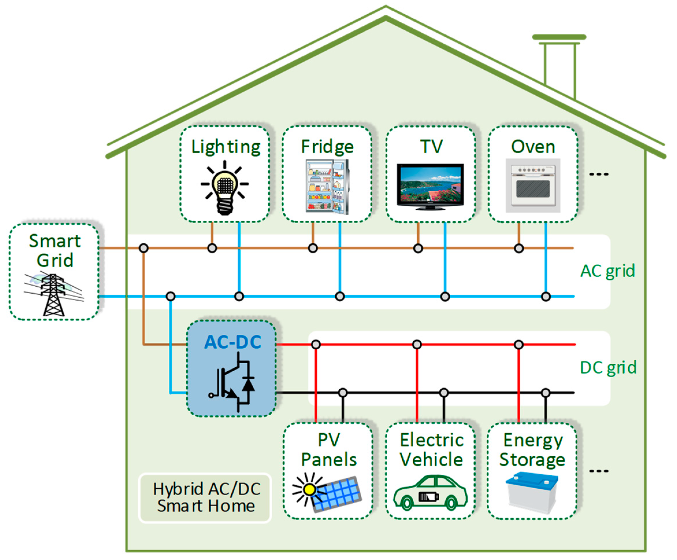
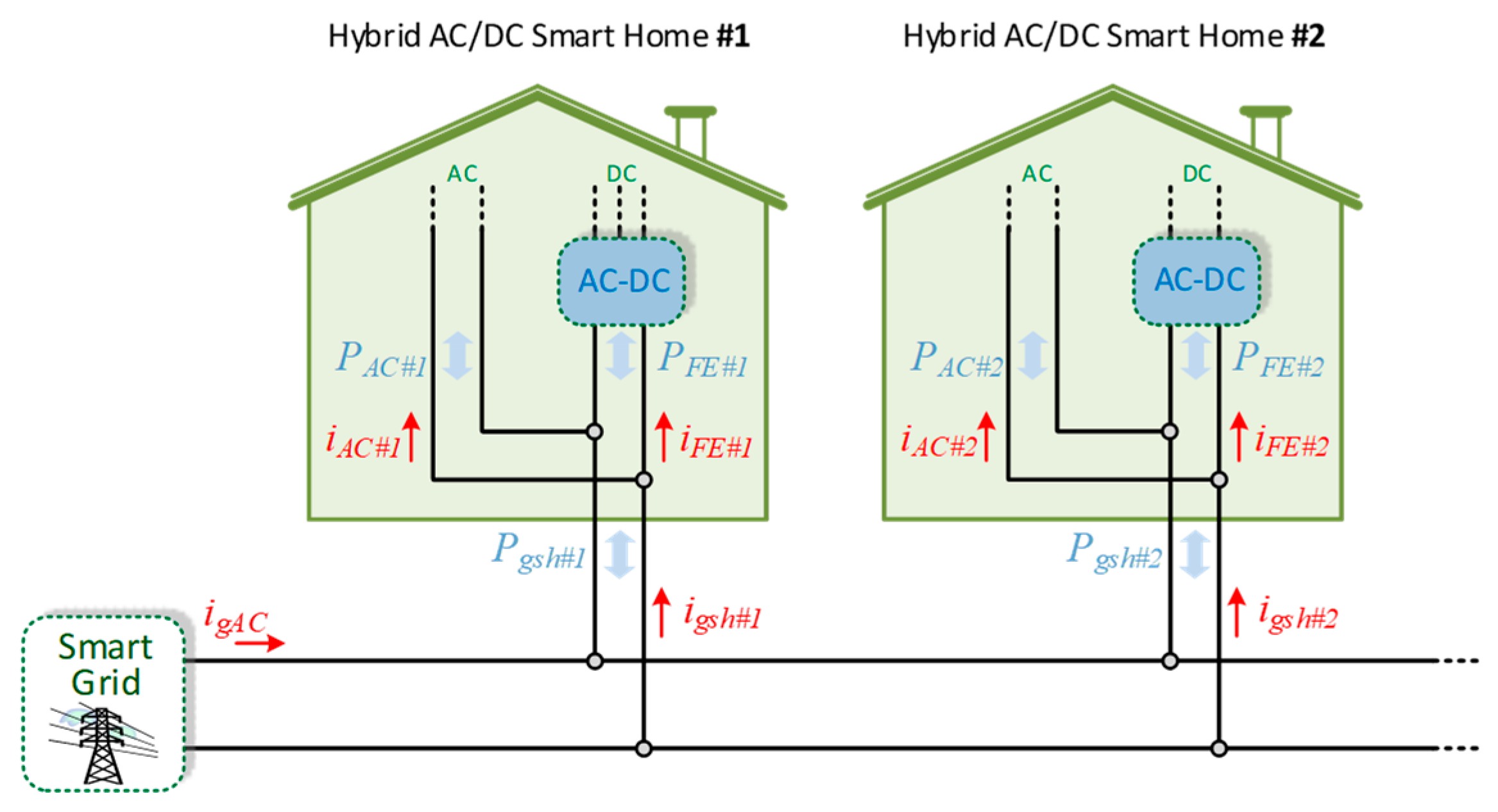
In this context, the focus of this paper is directly associated with the front-end AC/DC converter used in the power grid interface and in its innovative functionalities in hybrid AC/DC smart homes. Moreover, since each front-end AC/DC converter in each smart home can have multiple functionalities, much more than a simple interface with the electrical grid, it is possible to establish cooperative power management among a set of front-end AC/DC converters in different smart homes, offering particular attention to the contextualization with smart grids. As an example,
Figure 1 depicts a front-end AC/DC converter in a hybrid AC/DC smart home. As shown in
Figure 1, the AC loads are comprehended by lighting, fridge, TV, and oven. Nevertheless, other loads could also be considered as the air conditioners. On the other hand, at the DC grid are connected the PV panels, the electric vehicle, and the energy storage. Summarizing, as main innovative contributions of this paper, it can be emphasized: (a) Innovative and collaborative control algorithms for independent power converters (but with collaborative operations) for distinct operation modes, and respective contextualization and analysis in both smart homes and smart grids, of independent front-end AC/DC converters in hybrid AC/DC smart homes (i.e., each hybrid AC/DC smart home has a specific front-end AC/DC converter in terms of topology, but controlled with collaborative control algorithms), both for the smart homes and smart grids (e.g., permitting the operation with bidirectional active power, or producing capacitive or inductive reactive power for compensating the reactive power due to some electrical appliances in the AC grid of the smart home or smart grid, or producing specific harmonics of current aiming to compensate power quality problems due to electrical appliances with nonlinear behavior linked in the smart home and in the smart grid, or combining all of these possibilities in the same mode, i.e., operation with active power, reactive power and current harmonics); (b) Analysis of front-end AC/DC converters as a viable solution to establish unipolar or bipolar DC grids within the smart homes, highlighting the advantages and disadvantages, although the unipolar or bipolar type is only related with the DC grid, meaning that the proposed operation modes on the power grid side are always valid and are independent of the DC grid unipolar or bipolar type; (c) The digital control algorithms are implemented considering the possibilities to offer new operation modes in terms of perspectives for the smart homes within smart grids, and such innovative digital control algorithms can be implemented in both the traditional full-bridge and in a multilevel converter (or other topology), as experimentally validated in the paper, therefore, it is important to highlight that the digital control algorithms can be implemented in a power converter independently of the model and characteristics of switching devices and diodes; (d) Experimental validation of the proposed control algorithms for the front-end AC/DC converters (each one for distinct hybrid AC/DC smart homes and considering a traditional full-bridge and a multilevel power converter), operating at the same time, in the context of different smart homes (aiming to emulate a possible scenario of application in smart homes) and during the operation in the distinctive modes aligned with hybrid AC/DC grids, showing flexibility of operation with sinusoidal currents, as well as with distorted currents (for selective current harmonic compensation individually or in both smart homes), aiming to compensate power quality problems caused in the smart homes or smart grids (due to the linked electrical appliances with linear and nonlinear behavior). After this introduction, the front-end AC/DC converters are presented and described in
Section 2, including the main principle of operation of each topology (full-bridge and multilevel). The current control algorithm and the power theory strategies are presented in
Section 3. The experimental validation regarding the diverse operation modes is presented in
Section 4, which several experimental results with the developed laboratory prototypes. Finally, conclusions are given in
Section 5.
2. Hybrid AC/DC Smart Homes
As aforementioned, DC grids have gained more popularity, including at-home level, mainly due to: (i) Renewables production from PV panels is in DC; (ii) Energy storage from batteries is in DC; (iii) Instead of most of the electrical appliances are connected with AC grids, their internal circuits have DC supply; (iv) EVs connected with AC grids, and their internal circuits presenting DC supply; (v) There are smaller voltage drops; (vi) The power stages are reduced, leading to increase efficiency; (vii) Attenuation of power quality problems. Succinct, it is commonly predictable that hybrid AC/DC grids are grown and seen as the feasible solution in the perspective of smart homes framed in smart grids [
26,
27,
28]. In fact, several areas have been the subject of investigation: power electronics to interface DC homes are presented in [
29]; a comparison among nonlinear loads in ac and dc grids is presented in [
30]. Notwithstanding the unquestionable applicability of DC grids, imperative points requisite further attention in order to be overcome, including as pertinent points the protection and standards [
31,
32]. Taking into account this topic, European Union has announced some documentation, mainly regarding the legislation of voltage values [
33]. In this context, several works are ongoing for hybrid AC/DC grids applied to ancillary services [
34], power-flow control within the unified and sequential models [
35], advanced hierarchical control [
36], management and regulation strategies [
37], innovative schemes concerning generation [
38], and voltage levels when comparing AC with DC grids [
39].
2.1. Unipolar and Bipolar DC Grids
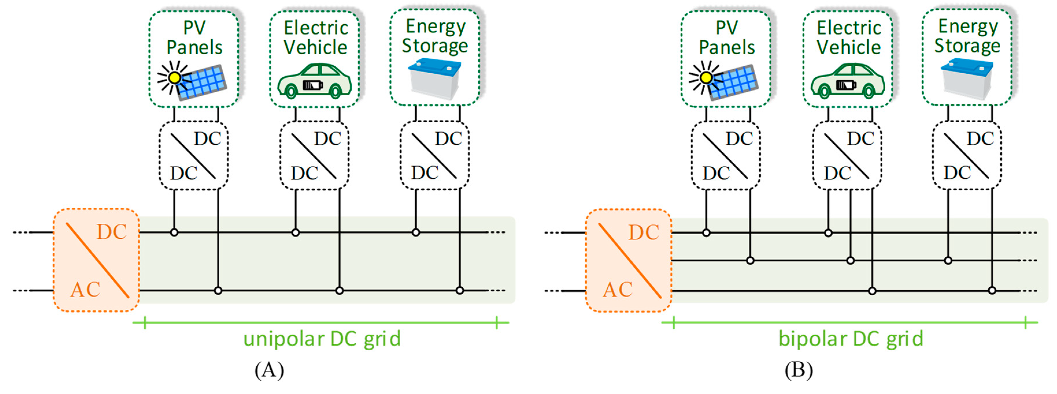
Regarding the structure of DC grids, two main configurations can be implemented: unipolar and bipolar [
34,
35]. With the objective to highlight the differences between them, an example of each one was introduced in
Figure 2. The unipolar is categorized by a two-wire configuration, thus it imposes a single DC voltage level, as shown in
Figure 2A. On the other hand, the bipolar is categorized by a three-wire configuration, resulting in two DC voltage levels. Based on a simple comparative analysis, the unipolar has less complexity in terms of design due to the lower number of wires, as well as less complexity in terms of control since it is based on a single voltage level. On the contrary, the bipolar requires an additional wire and the complexity is higher, nevertheless, it presents more flexibility, e.g., it is conceivable to interface technologies with distinct voltage levels. Furthermore, among other advantages, it should be highlighted the possibility to improve efficiency, resilience, and fault-tolerance. An assessment of promising technologies associated with bipolar structures is presented in [
40]. Despite such advantages, bipolar structures have an additional problem, which is related to the voltages unbalances due to the linked technologies and bidirectional operation. In the example illustrated in
Figure 2B, it is verified that some technologies are linked with two-wires and others with three-wires.
2.2. Structures of Hybrid AC/DC Grids
When the analysis is carried out in terms of structures of hybrid AC/DC grids, two main groups are recognized: coupled and decoupled. In the coupled, the AC grid of the hybrid AC/DC grid is linked to the main AC grid through a transformer (ensuring low-frequency isolation) with the DC grid established by an AC/DC converter. For the coupled AC configuration, two distinct approaches can be considered: (i) A DC grid with isolation from the main AC grid and with the hybrid AC/DC grid totally isolated (isolation provide in low-frequency); (ii) The isolation is provided in low-frequency for the AC grid and the DC grid is formed directly from the main AC grid, therefore, the hybrid AC/DC grid is partially isolated. On the other hand, the decoupled grid does not have low-frequency transformers on the AC side. Instead of it, such configuration has power converters on the AC side. By comparing both groups, it is common sense that the decoupled has higher costs mainly due to the AC/DC converter used in the interface among the main AC grid and the DC grid. Furthermore, one may note that solid-state transformers (SSTs) in the decoupled configuration are of paramount importance, guaranteeing isolation, constituting as the feasible substitute of low-frequency transformers. The decoupled configuration can also be divided into two approaches: (i) The hybrid AC/DC isolated from the main AC grid, where the front-end converter provides galvanic isolation; (ii) The hybrid AC/DC is partially isolated, where the front-end converter provides galvanic isolation only to the AC grid.
4. Digital Control Algorithms
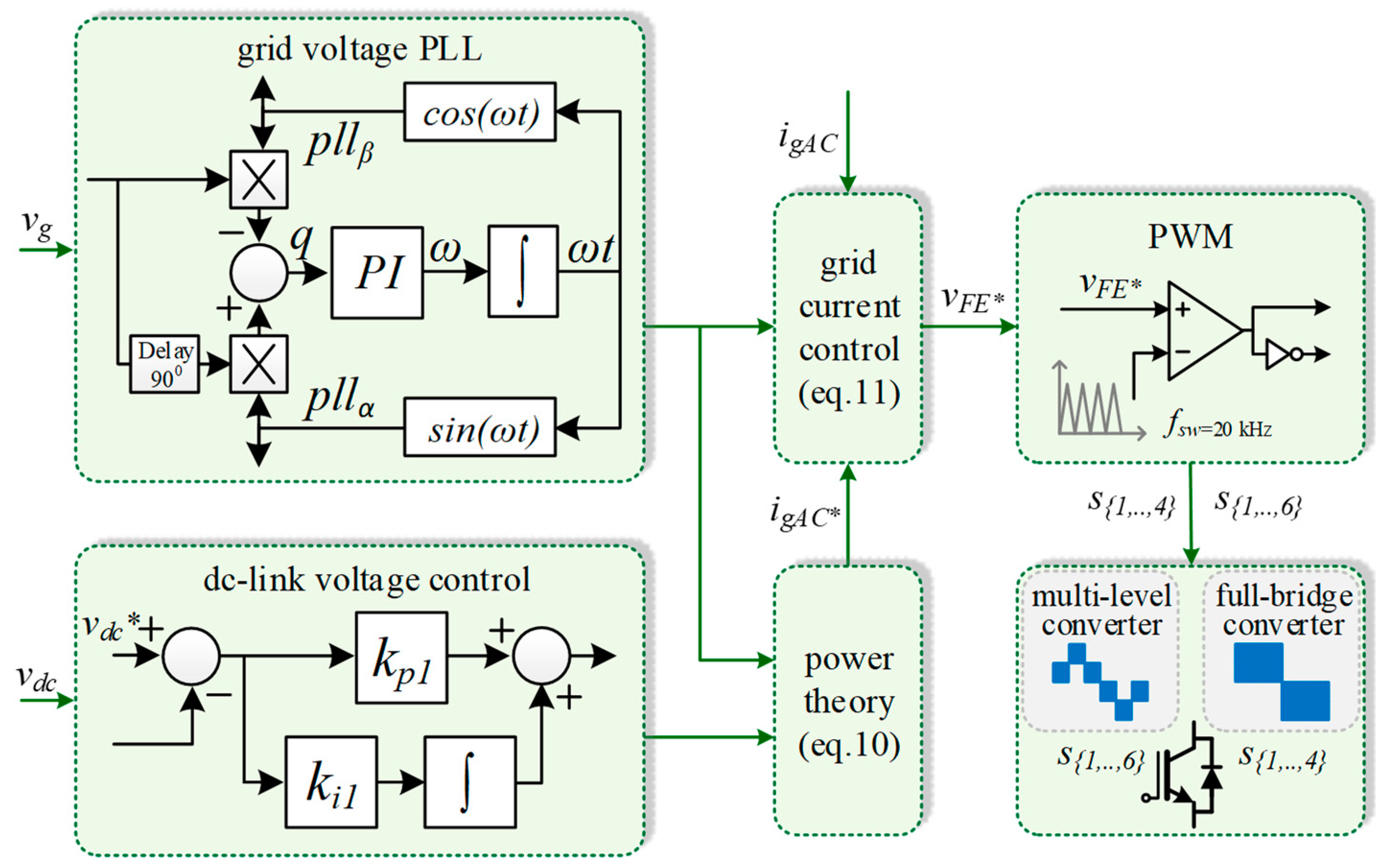
This section presents the control algorithms for the front-end AC/DC converters. From the point of view of the main AC grid, it presents as principle of operation: (i) Sinusoidal current and in phase or phase opposition with the voltage, when the converter operates only with active power; (ii) Sinusoidal current with voltage lag, when the converter operates with active and reactive power, or only with reactive power; (iii) Current with harmonic content, either in-phase or counter-phase with the voltage, when the converter is used to compensate for power quality problems. On the other hand, from the point of view of the DC side, the converter presents a voltage controller (in both power converters, the DC-link voltages are controlled by PI algorithms and
Figure 4. shows the implementation of such PI) to balance the dc-link voltages.
The operation of the front-end AC/DC converters just regarding active power is very similar: operation with a sinusoidal current in phase or phase opposition. Depending on the voltage waveform, two approaches can be considered in terms of control: (i) The current waveform can be adjusted to maintain a constant power from the power grid; (ii) The current waveform can be sinusoidal to guarantee high levels of power quality. Since the second option is the most beneficial from the power grid point of view in terms of operation with a sinusoidal current, a PLL must be used. The PLL is the initial algorithm executed by the digital system. In the scope of this paper, the implemented synchronizing algorithm is related to the three-phase algorithm [
41], but with the necessary adaptations to single-phase systems [
42]. When this PLL is synchronized, it is possible to obtain direct and quadrature components regarding the fundamental voltage of the power grid. Such signals are used for the subsequent control algorithms. The reference current (
igAC*) as a function of the active power is defined by:
where the term
pDC corresponds to the power on the DC side, meaning that it can assume positive or negative values, according to the position of the current sensor, which is reflected in a grid current in phase or phase opposition. The amplitude of the reference of current (
igAC*) is also influenced by the RMS (
VgAC) square value of the grid voltage, and by the instantaneous value of the grid voltage obtained from the PLL (
vgACPLLs), i.e., it can be controlled for consuming or producing active power and its amplitude is dynamically modified according to the variations of the grid voltage. In fact, the power on the DC side is composed of two distinct parcels, namely: the power for regulating both DC-link voltages (
pDClink); and the power effectively exchanged with the technologies connected to the bipolar DC grid (
pgDC). Therefore, the power on the DC side can be expressed as:
By analyzing Equations (1) and (2), one may see the DC-link voltage oscillation directly reflected in the reference of current, resulting in a non-sinusoidal reference waveform. This problem can be easily solved through a low-pass filter to attenuate the effect of the dc-link oscillation. As a consequence, instead of the DC-link presenting such oscillation, it is not reflected in the grid current. The control equation during the operation with active power is defined by:
This is the normal operation of the front-end AC/DC converters used to interface DC grids. However, the same structure of power hardware can be used for other purposes, especially, when it is connected to an electrical installation where are also presented AC loads directly connected to the power grid, as in the case of hybrid AC/DC smart homes. In such a case, the front-end AC/DC converter can be controlled, e.g., to compensate for the reactive power of the electrical installation. Moreover, it can produce a controlled reactive power (capacitive or even inductive) for the smart grid, i.e., independently of the power consumption/production of the smart home. Therefore, Equation (3) is not adequate since a signal in quadrature is necessary to adjust the phase angle between the reference of current and the voltage. Therefore, a parcel that includes the value of the reactive power and such quadrature signal (obtained from a PLL,
vgACPLLc) must be considered, resulting in the reference current defined by:
Analyzing Equation (4), distinct situations can be verified based on the operation of the front-end AC/DC converter: (i) Operation only to regulate the DC-link voltage of the DC-grid with active and reactive power equal to zero; (ii) Operation to regulate the DC-link voltage and only with active power to the DC-grid; (iii) Operation to regulate the DC-link voltage and only with reactive power to the AC-grid; (iv) Operation to regulate the DC-link voltage and with active power to the DC-grid and reactive power to the AC-grid, i.e., the front-end AC/DC converter operates in the PQ four quadrants. It should be noted that the reactive power is only exchanged on the AC side, such that DC-grid operation is not compromised. As abovementioned, the reference of reactive power can be defined based on the reactive power consumption of the AC grid on the smart home (e.g., the front-end AC/DC converter produces capacitive reactive power to compensate the inductive reactive power of the loads connected to the AC-grid of the smart home) or can be defined by the smart grid (in this case, the front-end AC/DC converter provides a service to the smart grid). Additionally, both situations can be combined, i.e., the front-end AC/DC converter can produce, at the same time, reactive power for both smart home and grid. This situation can occur, and it is only restricted by the power hardware. Moreover, the front-end AC/DC converter can also be controlled to produce harmonic currents for the smart home. In this case, instead of the reference current being distorted, the AC-side current of the hybrid AC/DC grid becomes sinusoidal. To implement it, the instantaneous values of the total current in the smart home (sum of the AC-load currents) are necessary. To define the reference-current component to harmonic compensation a strategy to determine the fundamental component of the load current based on the average value of the active power was considered. This reference-current component is determined as follows:
As can be seen, the harmonic compensation current (
igACh*) is dependent on the RMS value on the grid voltage and its instantaneous value. By combining Equation (4) and Equation (5), the final reference of current for the front-end AC/DC converter, contemplating all the possibilities of operation both for the AC grid and DC grid, is defined by:
In the perspective of digital implementation, Equation (7) can be is established throughout a complete sampling period [
k,
k + 1] according to:
where the average value
pea (i.e., the load active power) is established according to:
with
fg corresponding to the grid voltage frequency and
fs to the sampling frequency. On the other hand, the digital implementation of the RMS square value is established according to:
As abovementioned, a relevant contribution, in terms of operation of the front-end AC/DC converters, is the possibility to contribute to producing selected current harmonics in the context of smart grids. Such possibility can be totally independent of the operation in terms of active and reactive power (i.e., the operation on the AC-grid and DC-grid). Considering a real scenario of a set of smart homes in a smart grid, each smart home can be individually controlled to produce a specific current harmonic (e.g., a smart home operates with a third current harmonic and another smart home operates with a fifth current harmonic). Considering this relevant contribution in the perspective of having the front-end AC/DC converters of hybrid AC/DC smart homes operating for smart grids, the reference current must also consider such an opportunity. Therefore, the final equation that defines the reference of current is defined by:
where
H defines the harmonic amplitude and
ih[
k] the harmonic order obtained from a PLL. This final equation is then used in a current control strategy with a fixed switching frequency to provide the gate pulse pattern in each sampling period [
k,
k + 1]. Examining the front-end AC-DC converter in the point of view of the power grid, the relation among voltages and currents is defined by:
where the voltage
vFE is compared with a triangular carrier to define the PWM pattern for the switching devices.
Figure 4 shows the simplified block diagram of the control system based on the detailed control equations, where it is possible to visualize the sequence of control: the power theory and the current control do not consider the use of auxiliary signals synchronized with the fundamental positive-sequence component of the grid voltage; there is a control to keep the DC-link voltages regulated, independently of the operation mode; the power theory used to define the current reference according to the different possible operation modes (e.g., selective harmonic compensations and reactive power production); the grid current control according to its reference; the PWM modulation.
5. Experimental Validation
As previously mentioned, conventional front-end AC/DC converters are conditioned for producing sinusoidal currents in phase with the fundamental positive-sequence component of the grid voltages once distorted currents contribute to increasing power quality problems. In addition, distorted currents may lead to distorted voltages, contributing to the increment of harmonic power. On the other hand, the converter can also produce sinusoidal currents in counter-phase with the fundamental positive-sequence component of the grid voltages, forcing a flow of energy from DC-link to the AC grid. The analysis in terms of waveform is the same in both situations. For the experimental validation two hybrid AC/DC smart homes, one based on a multi-level converter and the other corresponding to a single-phase full-bridge converter, connected to the same smart grid, were considered. The validation was performed with the proposed cooperative operation of both AC/DC converters, in different test cases, connected to hybrid AC/DC smart homes, as well as in the context of smart grid proving ancillary services as a contribution to compensate power quality problems. Those features represent the main contribution of this paper.
Figure 5 shows the structure considered for the experimental validation, including two hybrid AC/DC smart homes (the developed prototypes were considered for the AC/DC power converters represented in
Figure 6). It is important to note that the unipolar or bipolar type is only related to the DC grid, meaning that the operation modes validated are always valid and independent of the DC grid unipolar or bipolar type. In the real implementation, two different setups, developed by the authors, were considered and this figure with the representation of smart homes is to contextualize the work and to demonstrate a real scenario of the application.
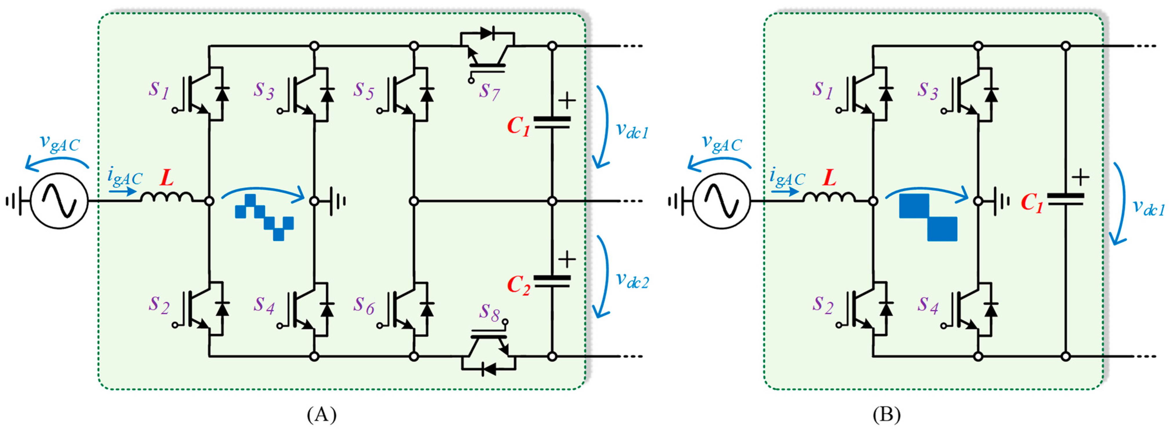
Figure 6 presents the front-end AC/DC converters for implementing aiming to emulate the two smart homes (
Figure 6A for the prototype with the multi-level AC/DC converter and
Figure 6B for the prototype with the full-bridge AC/DC converter). Both front-end AC/DC converters were used in the validation and at the same time to ensure the cooperative operation. It is important to highlight that the digital control algorithms can be implemented in a power converter independently of the model and characteristics of switching devices. In terms of implementation of both laboratory prototypes, the digital control algorithms were programed directly in the DSP TMS320F28335 (in low-level through the IDE code composer studio), were considered IGBTs with model FGA25N120ANTD, were considered IGBT Drivers with model HCPL3120, were considered coupling filters with the value of 5 mH/16 A and DC-link capacitors with a value of 820 μF/400 V, and were considered current sensors with model LTSR 15-NP and voltage sensors with model LV 25-P. As mentioned, the digital control algorithms were programmed in the DSP, where an RS232 interface with a computer was also implemented to define setpoints of operation, therefore, allowing to emulate setpoints received from a smart grid (e.g., in terms of operation with reactive power and current harmonics). Additionally, such an interface also permits receiving relevant data from the power converters.
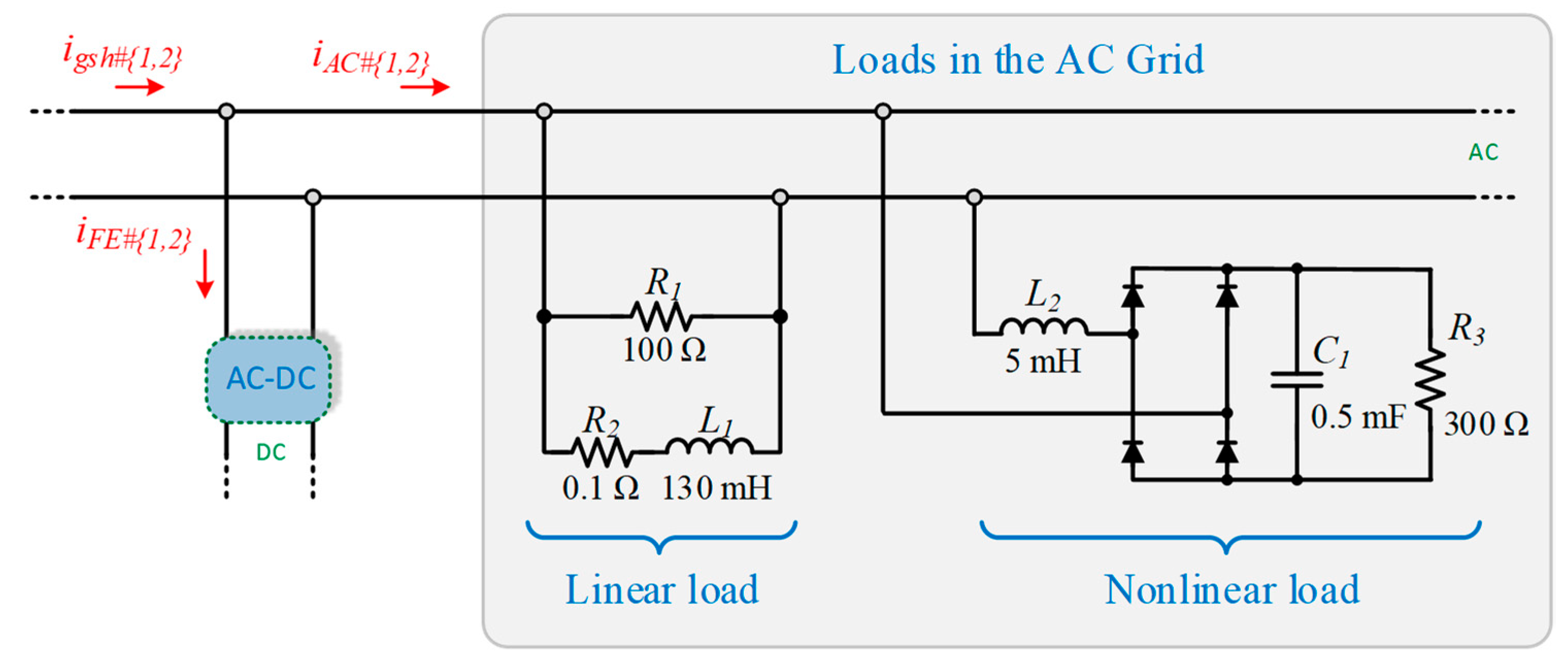
Figure 7 shows the implanted linear and nonlinear loads in the experimental prototype connected to the AC grid. Thus, the load currents present harmonic distortion and are out-of-phase in comparison to the grid voltages (i.e., operation with reactive power and currents with harmonic content).
A first experimental validation was performed considering just a single smart home.
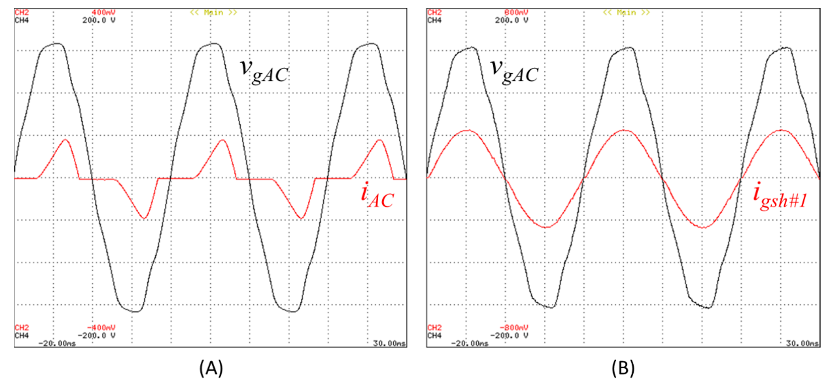
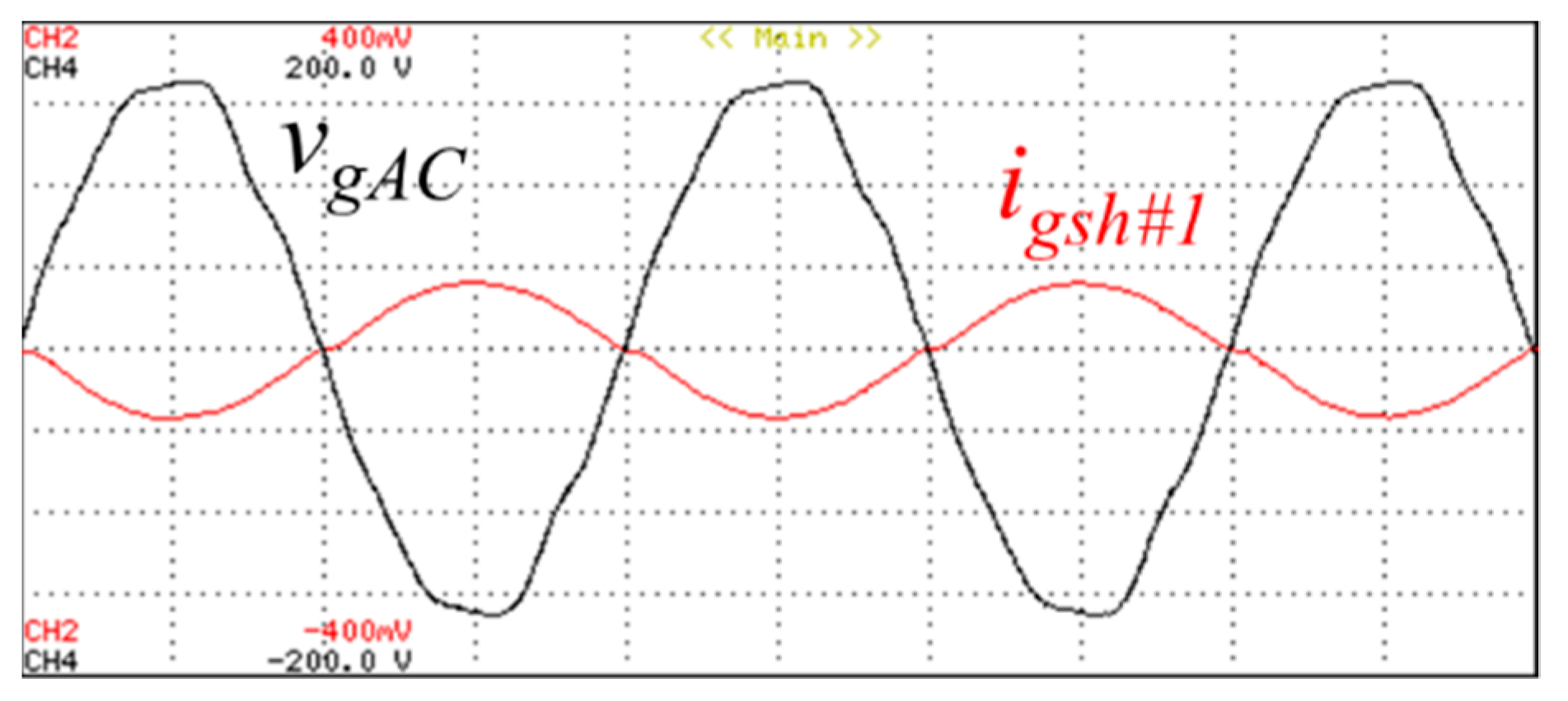
Figure 8 shows the main results when the front-end AC/DC converter is controlled for demanding an energy flow from de AC-grid to the DC-link and, moreover, compensating the distorted currents drawn from the nonlinear loads connected in the hybrid AC/DC smart home, i.e., connected to the internal AC grid. These results are aligned with the contributions of this paper, permitting to compensate power quality problems caused by the nonlinear loads.
Figure 8A shows the AC-grid main voltage (
vgAC) and the consumed current just in the AC grid of the hybrid AC/DC grid (
iAC), i.e., the smart home-drawn current. As verified,
iAC is highly distorted, which can accentuate, if not compensated, power quality problems in the AC grid. On the other hand,
Figure 8B shows the same voltage and the total current consumed by the hybrid AC/DC smart home (
igsh#1). In this case, additionally, to absorb active power for the DC grid, the front-end AC/DC converter is also controlled for compensating the current of the internal AC grid, resulting in a sinusoidal current. These results permit verification of the benefits for the smart grid, where the whole smart home presents a sinusoidal current consumption and unitary power factor (the power quality problems, from the smart grid point of view, are eliminated). Regarding the results of
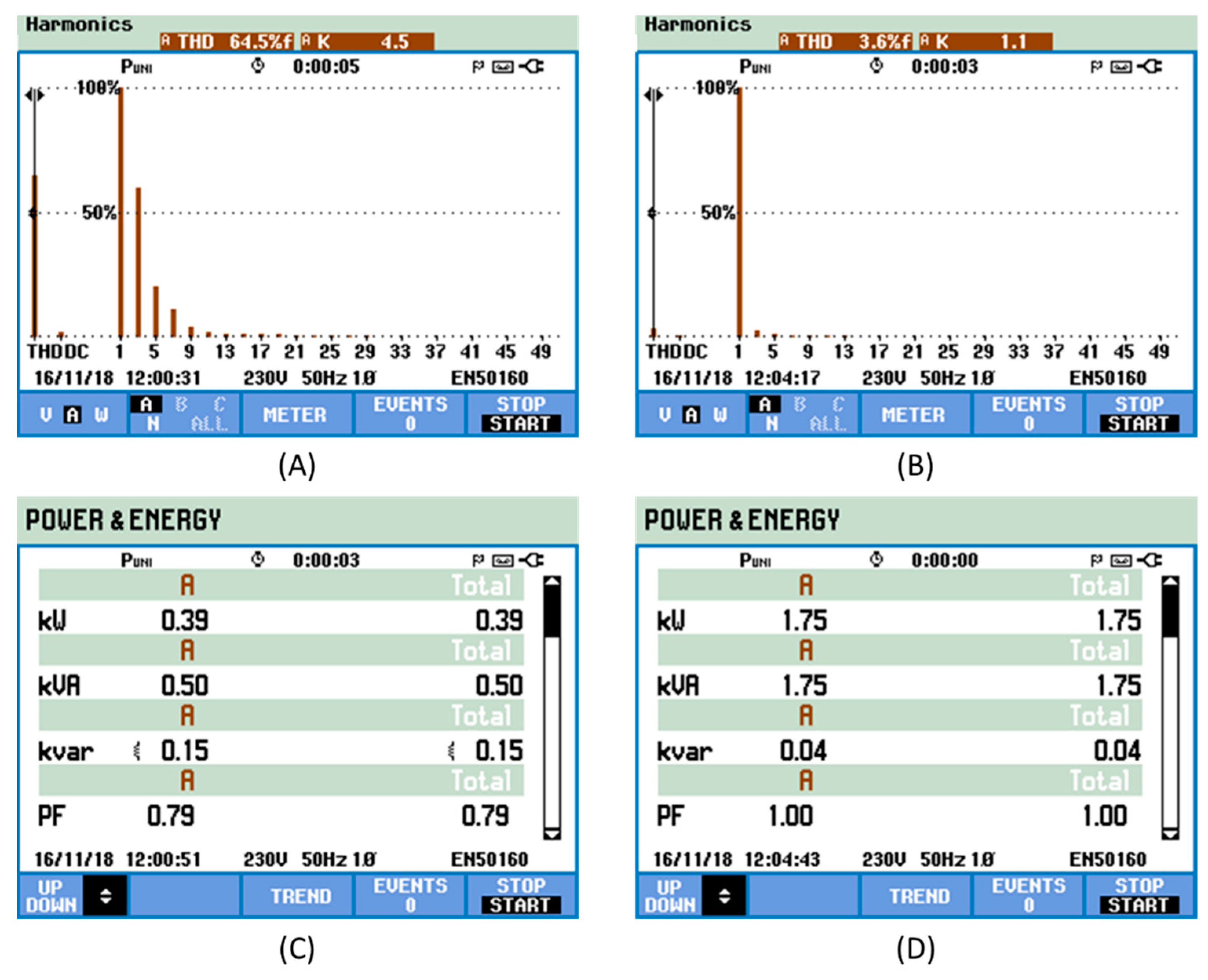
Figure 8,
Figure 9 shows the consumed powers, the power factor and the harmonic spectrum, respectively, for the cases reported in
Figure 8.
Figure 10 shows experimental results regarding the voltage (
vgAC) and the current of the AC grid of smart home #1 (
iACsh#1) on the main AC grid when the front-end AC/DC converter is injecting energy into the power grid. As it is possible to visualize, the voltage presents a distortion, but the current is sinusoidal and in phase opposition with the voltage, meaning that the power grid is receiving energy from the front-end AC/DC converter, which is acting as a grid-tied inverter (with current control feedback).
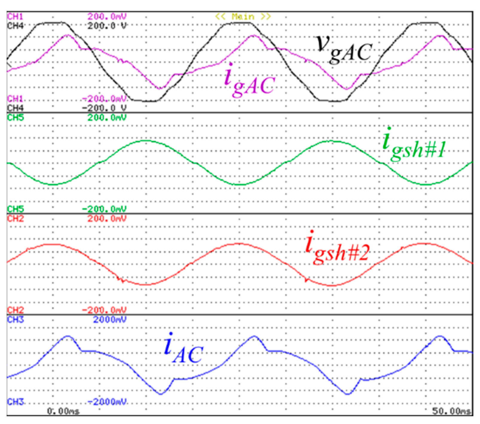
Figure 11 shows an example of the front-end AC/DC converter operation within hybrid AC/DC smart homes, which comprehends the AC voltage (
vgAC), the AC current (
iAC), the consumed current by each front-end AC/DC converter of each smart home (
igsh#1 and
igsh#2) and the AC current of smart home #1 (
iACsh#1). As can be observed, the AC main current (
igAC) is distorted due to the operation of the AC grid of smart home #1. In this case, one may note both front-end AC/DC converters of both smart homes operating simultaneously and drawing sinusoidal currents, with the smart home #1 converter producing active power, while smart home #2 converter is absorbing active power. As shown, these results validate an important contribution, where each smart home operates with a sinusoidal current from the smart grid point of view. Moreover, these results also validate the operation in bidirectional mode. Moreover, both converters are operating with the same active power magnitude, meaning that the current in the main AC grid corresponds to the current in the AC grid of smart home #1 (in this case, a distorted current).
As aforementioned, one of the main contributions that the front-end AC/DC converters can offer, additionally to operating from the perspective of smart homes, is the combined operation with several smart homes, establishing an added value for smart grids. Thus, in addition to a bidirectional operation with active power, e.g., each front-end AC/DC converter can produce controlled reactive power and/or current harmonics.
Figure 11 depicts the experimental results of both AC/DC converters operating simultaneously. Furthermore, there are in the experimental setup two smart homes, each one with a front-end AC/DC converter. Based on the experimental results, one may see the control of the consumed reactive power and harmonic currents, according to the smart grid needs. These features demonstrate the relevance of this paper.
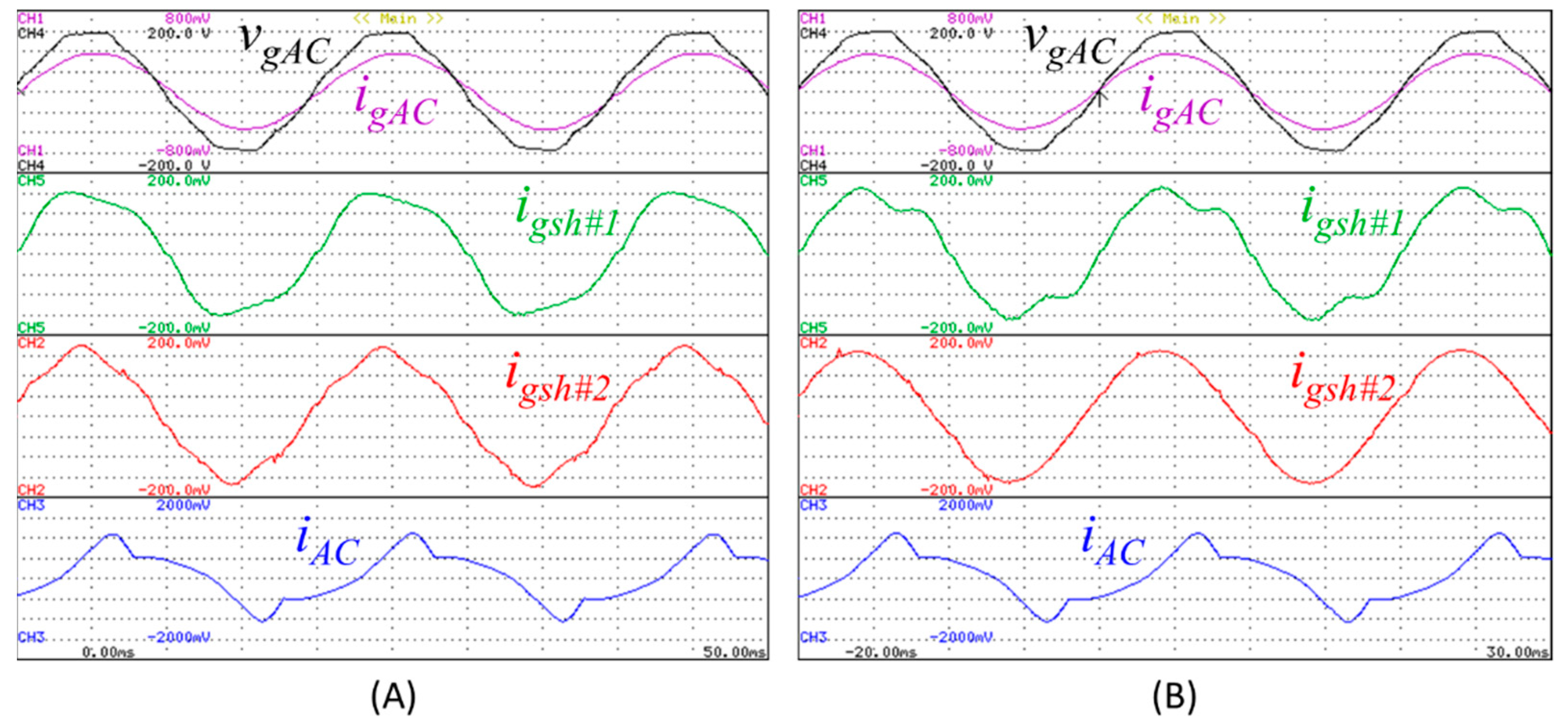
Figure 12 shows the experimental results of the AC grid voltage (
vgAC), the total AC grid current (
igAC), the consumed current by each front-end AC/DC converter of each smart home (
igsh#1 and
igsh#2) and the AC grid current of smart home #1 (
iACsh#1), which, as can be seen, presents harmonic distortion and reactive power consumption. These results were obtained to validate the proposed operation modes, where the two AC/DC converters are operating simultaneously to mitigate power quality problems. Furthermore,
vgAC,
igAC, and
iACsh#1 are exactly the same in both cases (
Figure 12A,B), differing only by the current of each front-end AC/DC converter of each smart home operates. Regarding the result shown in
Figure 12A, in the case of smart home #1, the front-end AC/DC converter is controlled to compensate for the third-order harmonic current. On the other hand, in the case of smart home #2, the front-end AC/DC converter is controlled to compensate for the fifth-order harmonic current. In the first situation, as it can be seen, the total AC grid current becomes sinusoidal, with a phase delay in relation to the grid voltage since the reactive power was not compensated. Regarding the result shown in
Figure 12B, in the case of smart home #1, the front-end AC/DC converter is controlled to compensate for the third and fifth-order harmonic currents. On the other hand, the front-end AC/DC converter of smart home#2 is controlled to compensate for the reactive power. In this second situation, as it can be seen, due to the proposed operation mode, the total current of the main AC grid becomes sinusoidal and the reactive power is compensated (i.e., the power factor becomes unitary), despite the consumption of non-sinusoidal current due to the AC grid in smart home #1. It is also noteworthy that the active power consumption by the converters, due to the DC grid is not compromised due to the operation to compensate for power quality problems on the AC side, which is an important feature.


 ,
, 


