
Electric Motors for Variable-Speed Drive of Lock Valves


1
Electrical Engineering Department, Novosibirsk State Technical University, 630073 Novosibirsk, Russia
2
Department of Technology and Communication Systems, Seifullin Kazakh Agrotechnical University, Nur-Sultan 010011, Kazakhstan
*
Author to whom correspondence should be addressed.
Electronics 2021, 10(21), 2727; https://0-doi-org.brum.beds.ac.uk/10.3390/electronics10212727
Submission received: 11 October 2021
/
Revised: 1 November 2021
/
Accepted: 5 November 2021
/
Published: 8 November 2021
(This article belongs to the Special Issue Advanced Technologies in Energy-Efficient Convertors)
Abstract
:Improving the operational reliability of nuclear power plants, combined heat and power plants (CHP), as well as oil and gas pipelines is a priority task in the development of a variable-speed drive for lock valves used at these facilities. This paper analyzes the technical requirements for such devices: the motor has been selected, its electrical equilibrium and moment equations have been obtained; recommendations for the selection of the kinematic drive scheme have been formulated. Based on the theoretical data obtained, a prototype has been developed, manufactured, and tested.
1. Introduction
A developing, designing, and producing adjustable lock valve plays an important role in ensuring human life. Thus, the annual global demand for valves of only one type, high-pressure steam with setup diameters from 20 mm to 350 mm used at nuclear power facilities and heat and power plants, amounts to tens million pieces per year, and the cost of some samples can exceed USD 50,000.
Various researchers have dealt with the design problems of new electrical machines with an increased starting torque. Work [1] presents a modified method of the predicted torque control of induction machines. This method allows for the reducing of the torque ripple at the moment of starting a highly loaded AC electric motor. The modified predictive torque control results in a more stable starting behavior of the electric motor in relation to torque ripple control methods compared to conventional direct torque control. Field control (FOC) and direct torque control (DTC) methods are reported to be the two most commonly used control methods for induction machine (IM) drives operating under severe starting conditions. However, the data for the methods are already technically outdated enough [2,3]. DTC and FOC methods associated with the direct self-control of the starting torque were introduced into the industry at the end of the 1980s [4,5,6]. Commercial use in manufacturing lock valve drives was developed in the mid-1990s [7]. The presented methods did not completely ensure the stable operation of the electric motor in the low-speed range, and did not allow us to get rid of the torque ripples at the start completely. There are also known methods of variable load control and space-vector modulation (SVM), which provide a more stable operation for an AC motor at low speed, as discussed in [8]. Improvements to the DTC method can be found in [9], but even all of the improvements do not allow for the efficient control of the lock valve drive without the use of a gearbox. In parallel with the methods considered above, model predictive control (MPC) methods based on the use of power electronics were developed. They are considered in works [10,11,12,13,14]. There are various options for MPC implementation, such as, for example, the finite control set model predictive control (FCS-MPC) used for motor start control, though requires the significant computational power of the control system due to the fact that it is necessary to calculate the weighting factors for all possible transients. Many researchers have improved this method with a combination of modern control methods to increase MPC reliability [15,16,17]. It also provides information of the empirical procedure for obtaining suitable weighting factors [18]. Through the direct use of the considered methods, it is impossible to control the drive without a gear valve, since, at the start, it is possible that the stem will be stationary due to the slagging of the cone. In this situation, the current protection must be triggered in order to prevent the failure of the electric motor. The value of the phase current should change in a small range in all the operating modes of the electric drive, from idle to short circuit. It is also desirable to remove the current and thermal protection from the electric circuit of the drive and to not introduce into the control system a time limit for working out a given movement. This requires a different drive control principle and a completely different design. Thus, in [19], there is the information of induction drives that have a strongly nonlinear characteristic. It also presents the results of research carried out on a 50 HP asynchronous motor driven by a three-phase inverter, which provides high-quality speed and torque control. The IM torque control, IM-using FOC has been considered quite often in past studies. In [20], various methods of slip control are presented for different modes of starting an electric motor at different loads. There is also information on the adaptive control of the sliding mode [21]. Work [17] proposes simplified models for the convenient fixation of the transient processes of an AC electric motor, which can be used in the design of induction machines, but this model is rather simplified and has lost its relevance at the present time [22]. There are studies presented in [23] related to duty cycle modulation, direct torque control, and brushless machines with double feed. For a brushless double feed machine (BDFM), traditional direct torque control (DTC) has many problems such as a large output torque ripple and undefined inverter switching frequency. The presented control method has several advantages over traditional direct torque control while reducing the ripple flux linkage. There are also proposed measures to optimize direct torque control. The SVM-DTC algorithm [3] can effectively reduce the torque ripple, but it requires large calculations and additional parameters, which cannot be used for lock valves due to the increased cost of the control system. There is some information of the methods of monitoring the magnetic fields of permanent magnet synchronous machines using a Texas Instruments F28343 200 MHz microcontroller [24]. There are similar works related to the regulation of electric machines with permanent magnets, which provide an algorithm for finding the optimal current vector [25], analytical solutions [26], and the search for methods to minimize losses [27,28]. In addition, work on tuning PID controllers for electric drive control systems, as well as control methods with an observer, have been previously considered [29,30]. There are research results in the aspect close to this work, where the reversible dependence of the speed and the time of an asynchronous machine at start-up without load and with load were considered, based on the induction parameters. An equivalent circuit of the machine and a description of the torque equation method was presented. Analytical expressions of the speed dependence on the time of an asynchronous machine with a direct start have been considered. The process of starting an electric motor with a large starting torque is a rather serious scientific and practical problem [31,32,33]. IM starting methods are based on the use of soft starters [34] or by shunting the stator and rotor windings, which are quite outdated [35], as well as on the use of power electronic devices [36]. In work [37], the calculation of the permanent magnet synchronous machine parameters, taking into account characteristics of the load, is presented.
The following is a list of the main requirements that must be taken into account when designing drives for lock valves [38]:
- A high degree of protection from the environment. As a rule, motors and control systems are designed with protection no less than IP54 (closed, protected design allowing the presence of water jets at any point on the outer surface of a technical object);
- Significant excess of the maximum torque at start, in comparison with the nominal value with free movement of the stem. Therefore, examining a high-pressure steam valve with a setup diameter of 20 mm, it was found that in the nominal mode, the torque of 5–10 Nm is required (depending on the equipment wear), and when the “slagged” stem is torn off in the closed state, the torque increases to 80 Nm;
- Low speed of the drive output shaft at the level of 10–20 rpm, which should exclude the possibility of hydrodynamic shock. Therefore, in drives that do not provide for speed variation and operating in the “start-stop” mode, it is necessary to use gearboxes with a large gear ratio. Traditionally, in such valves, asynchronous motors are most often used. They are designed for an output shaft speed of 1000 rpm and 1500 rpm. Therefore, for them, the minimum value of the reduction factor is 50 units, and this is a rather complex and expensive technical object;
- There are practically no requirements regarding the limitations of the dimensions and weight of the electric actuator of lock valves;
- Difficult access to many objects of the lock valves. This feature is most significantly manifested in heating plants, as well as in the areas of oil and gas pipelines remote from settlements;
- High reliability of protection of motor windings from overheating and maximum permissible currents.
An analysis of the above-mentioned data inevitably leads to the need to solve the problem in which two mutually exclusive requirements are laid: the first one is taking into account the peculiarities of operation. It is necessary to simplify the control system as much as possible, since the elements of power electronics are most susceptible to the effect of the environment and are the “weak link” of the entire drive. The second requirement considers that, if you design an induction drive that does not include the possibility of speed regulation, then, in the starting mode, the current in the windings will increase by 5–8 times. This means that, if within a short time interval the torque on the shaft does not decrease to the nominal value, the current protection must be triggered. In such a situation, when there is not enough time to start the movement of the stem, there is a need for a repeated (or multiple) switching on of the drive, and, in extreme cases, the use of human physical strength [39,40,41].
Thus, the ideal solution to this problem is the use a motor in the drive with the following characteristics:
- When connected to an industrial network of alternating current 50 Hz (or 60 Hz), the shaft rotation frequency will be 10–120 rpm, which will either get rid of the gearbox in the drive kinematic diagram, or eliminate the problem of developing a complex mechanical transmission;
- The value of the specific moment (the ratio of the moment to the mass of the drive) is comparable to that of a drive containing an asynchronous motor and a gearbox [42];
- There are no moving contacts due to the presence of a collector, slip rings, etc. This condition is most significant when it comes to the explosion-proof version of the drive;
- The value of the phase current varies in a small range for all modes of operation, from no-load to short-circuit. If this condition is met, then it becomes possible to remove the current and thermal protection from the drive and not to introduce into the control system a time limit for the specified movement.
This set of requirements is most satisfied by inductor motors with electromagnetic speed reduction (MER).
Therefore, in the presence of winding of an armature with the number of pole pairs , in an unregulated operating mode, and powered from an industrial network of 50 Hz, MER provide the output shaft speed rpm, and due to good dynamics, are able to reach a synchronous speed with a maximum torque. This feature makes it possible to simplify the control system to the limit, for example, to build a drive using an industrial network and finite elements, which ensures the closing (opening) of the valve with practically no power electronic elements.
Also important is the absence of moving contacts (brushes, slip rings, etc.) in the construction of the machine. This greatly simplifies the protection from the environment. Note: if there is a limitation on heat losses, then only synchronous motors with high-coercive magnets on the rotor can be compared with DER in terms of weight and dimensions. Asynchronous machines have similar parameters (weight and dimensions at a fixed torque value) that are 5–6 times worse. However, the most important advantage of motors with electromagnetic speed reduction is their ability to operate for a long time in modes close to a short circuit, which in some cases makes it possible to completely eliminate overcurrent protection even with natural cooling. All these features are clearly demonstrated in [43], where the characteristics of the serial 23PP motor from SAGEM and DER-0.7, developed and manufactured by one of the authors of the article, are compared. The electrical losses in the armature windings of these machines do not exceed 3.4 W. In this case, the motors create a torque of 0.5 Nm and 0.7 Nm, respectively. For example, if the same torque is generated by an induction motor (IM) at a rotational speed close to 1500 rpm, then its net power will be in watts. Analyzing these values may highlight how it is difficult to imagine an asynchronous micromachine, the efficiency of which would be at a level of 0.97. Let us show that, with the same dimensions and electromagnetic loads, the MER has serious advantages over synchronous motors with permanent magnets on the rotor.
For example, if we take an inductor machine with a distributed winding on the stator and a ring magnet on the rotor, then the excitation field for it will be determined as
where is the constant component of magnetic induction due to the flow of magnets; is the coefficient of the magnetic conductivity of the air gap pulsation; is the number of rotor teeth; is the number of periods of changing magnetic conductivity equal to the number of pole pairs ; is the angle along the inner surface of the stator; is the angle of rotation of the rotor; is the angular frequency of rotation. In the linear formulation of the problem, substituting (1) into the energy equation and differentiating the result by the angle of rotation of the rotor, we obtain the expression for the electromagnetic moment
Here: is the stator inner diameter and active length; is the initial value of the angle of rotation of the rotor. The number of rotor teeth and the number of pole pairs in an inductor machine with axial excitation, having an electromagnetic speed reduction, is related by the ratio:
Then, the ratio of the maximum moments of an inductor machine with an axial flux and a classical synchronous machine with permanent magnets on the rotor with unchanged dimensions, electrical losses, the number of pole pairs and the current density will be equal to:
which is in complete agreement with earlier estimates, for example, in [44,45].
Now let us compare the capabilities of two inductor machines with excitation from ring permanent magnets, provided that one of the machines has a distributed winding on the stator, and the other one has a winding with a toothed pitch [46]. To simplify the analysis, we represent the excitation field and MMF in the form of idealized discrete Rademacher functions, as it was done in [44]. If we do not touch upon the design features of the magnetic system and assume that the fundamental harmonic of the field is the same as in the previously considered cases, then:
Here, is the number of elementary teeth located on the inner surface of the large teeth, in the grooves between which the winding is laid; is the difference between the maximum possible and accepted in the design of the value.
Using the previously obtained expressions [47], we find the ratio of the moments of an inductor motor with a distributed winding on the rotor and a synchronous machine with permanent magnets on the rotor:
where , based on the recommendations for selecting the geometry of the notched-groove zone, takes values from three to six. Thus, in the linear formulation of the problem, the torque of the inductor motor is 4.6–6 times higher than that of a synchronous machine with magnets. This gives grounds to assert that the proposed engine has solid technical advantages over other types of electrical machines and can be considered as the basic option when designing a lock valve drive with a coaxial planetary gear.
2. Mathematical Model
The most famous representative of electric machines with an axial flow is a two-phase stepper motor with electromagnetic speed reduction, made according to. The motor contains a toothed two-pack rotor and a stator. An annular magnet is located between the packages of the rotor and produces a unipolar magnetic flux within each half of the machine. There are eight large teeth on the stator, on the inner surface of which there are elementary teeth with a toothed division close to or equal to the tooth division on the rotor. The coils belonging to phase A are placed on large stator teeth, the geometric angle between which is 90 degrees. The other four teeth with coils belong to phase B.
If positive voltage is applied to phase A, then under two diametrically located large teeth, the unipolar field is enhanced, and under large teeth that are offset by the angle of 90 degrees, it is weakened. With an appropriate selection of the number of elementary teeth on the stator and rotor and , the rotating part of the electric machine is magnetically an elliptical ferromagnetic blank. Such a “rotor” will always strive to take such a position when the minimum air gap is in the area where the magnetic field is maximum. When the voltage polarity on phase A changes, the “rotor” will rotate 90 electrical degrees or by . The development of intermediate positions that are multiple to is carried out by disconnecting phase A from the power source and the corresponding switching in phase B.
In the considered design, several negative factors can be distinguished:
- To develop a large unipolar flux, it is necessary to increase to the limit the ratio of the bore diameter to the inner diameter of the rotor. Otherwise, it is necessary to reduce the length of each stator (rotor) package or to develop a multi-package structure. However, such a step entails a relative increase in the non-working zones (between packets) and, as a consequence, a decrease in the specific moment;
- To close the unipolar flux along the stator, a massive ferromagnetic housing is required to eliminate this negative factor, the French company SAGEM makes the stator packages not lined but limits the maximum rotational speed to 18–20 rpm;
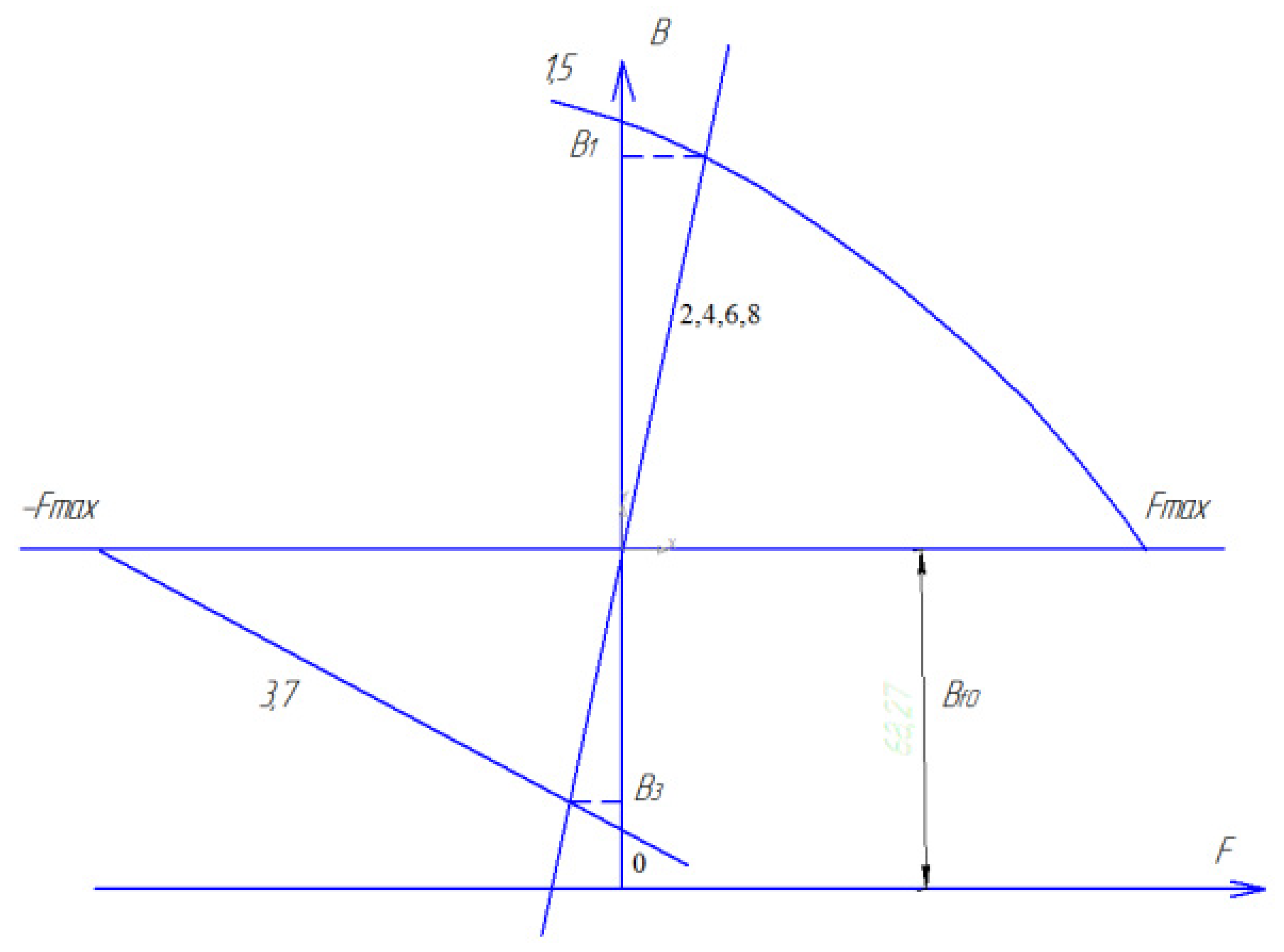
- With a small cross-section of the groove, it is impossible to develop an armature flux of the required magnitude, since it closes along a long path (a quarter of the circumference) with high magnetic resistance. Additional decrease is due to the branching of magnetic field lines in the area where there are no currents (2, 4, 6, 8; Figure 1), which is clearly demonstrated by the problem in the graphic-analytical calculation of the field.
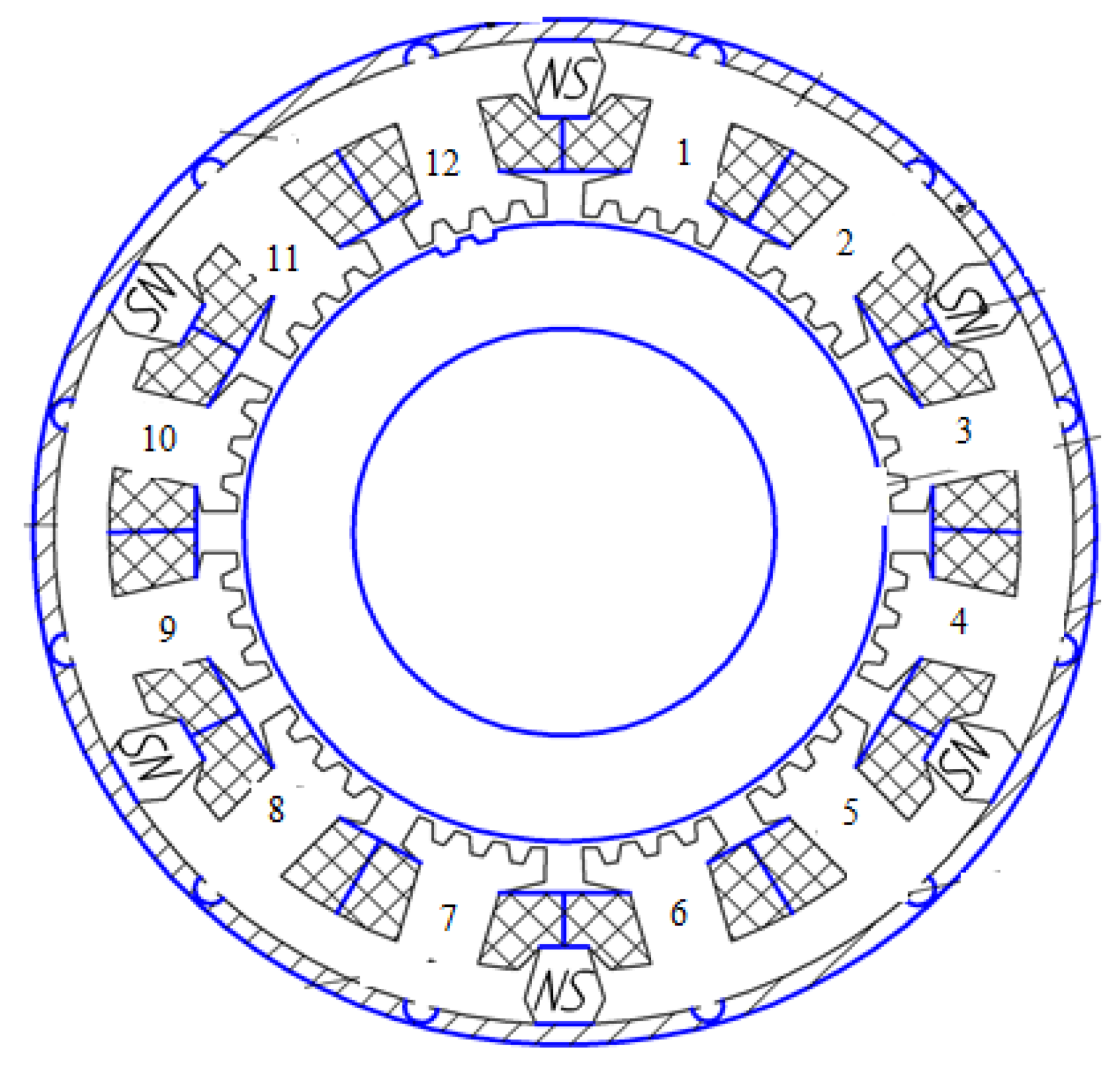
To eliminate the indicated drawbacks in the motor for the drive of lock valves, it is necessary to: (a) Place permanent magnets that develop a radial flow on the stator; (b) Combine the coils belonging to the same phase on magnetically isolated segments. The set tasks are fully solved in the design of the electric motor made according to [48] (see Figure 2). Here, the stator package is divided into 2 mk (k = 1, 2, 3, … is an integer) of segments, each of which has large teeth with coils belonging to the same phase. The coils are in aiding connection in order to mutually reinforce each other’s magnetic fluxes. Permanent magnets are located between the segments developing a radial field of excitation of the same polarity within the segment. Thus, if one coil amplifies, the other weakens the resulting field.
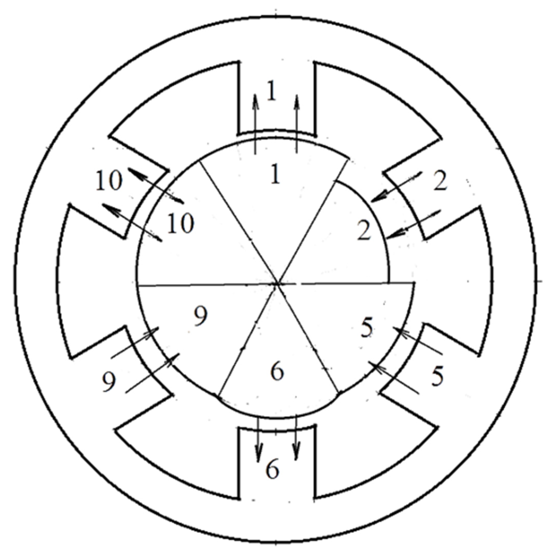
In contrast to the two-phase analogue considered above, here, due to the magnetic isolation of the segments, the armature field is weakened only due to the scattering fluxes and, as calculations show, it turns out to be 10–15% greater than the field under the large teeth 1, 5 (Figure 3). Another positive feature of the motor is that the excitation flow and the armature flow are closed in different parts by a yoke and come together only in the “right places”: the air gap and the large tooth. For example, the excitation flux from the top magnet in Figure 4 closes along large teeth 1, 12, and the areas with a yoke between them, and the anchor flow closes only along large teeth 1, 2, and the areas with a yoke between them. This allows for the minimizing of the height of the rotor yoke and for the designing of the motor with a large internal bore in the shaft required for the valve stem to pass.
It is also important that there is no unipolar flux (magnetic circuit) in the machine under consideration, which greatly simplifies the design of the motor. We also note the main feature of the proposed technical solution: the absence of a rotating magnetic field, which at first glance contradicts the fundamental provisions of the general theory of electrical machines. This “paradox” is explained as follows. Let us select in the motor large teeth (segments), within which the field of excitation has the same direction: 1, 2-phase A; 5, 6-phase C; 9, 10-phase B. Suppose that, with a fixed position of the rotor, magnetic conductivity of the air gap within each large tooth is determined as shown in Figure 3 and is provided with a different distance between adjacent elementary teeth located on different large teeth. In this case, it can be assumed that within each large tooth, “its own rotor” rotates with the frequency. It presents a ferromagnetic segment located with the eccentricity relative to the stator and having “its own initial phase”. If we mentally cut such a machine into six parts and rearrange its individual fragments accordingly, the mathematical analogue of a real motor appears as shown in Figure 4.
3. Control Algorithm
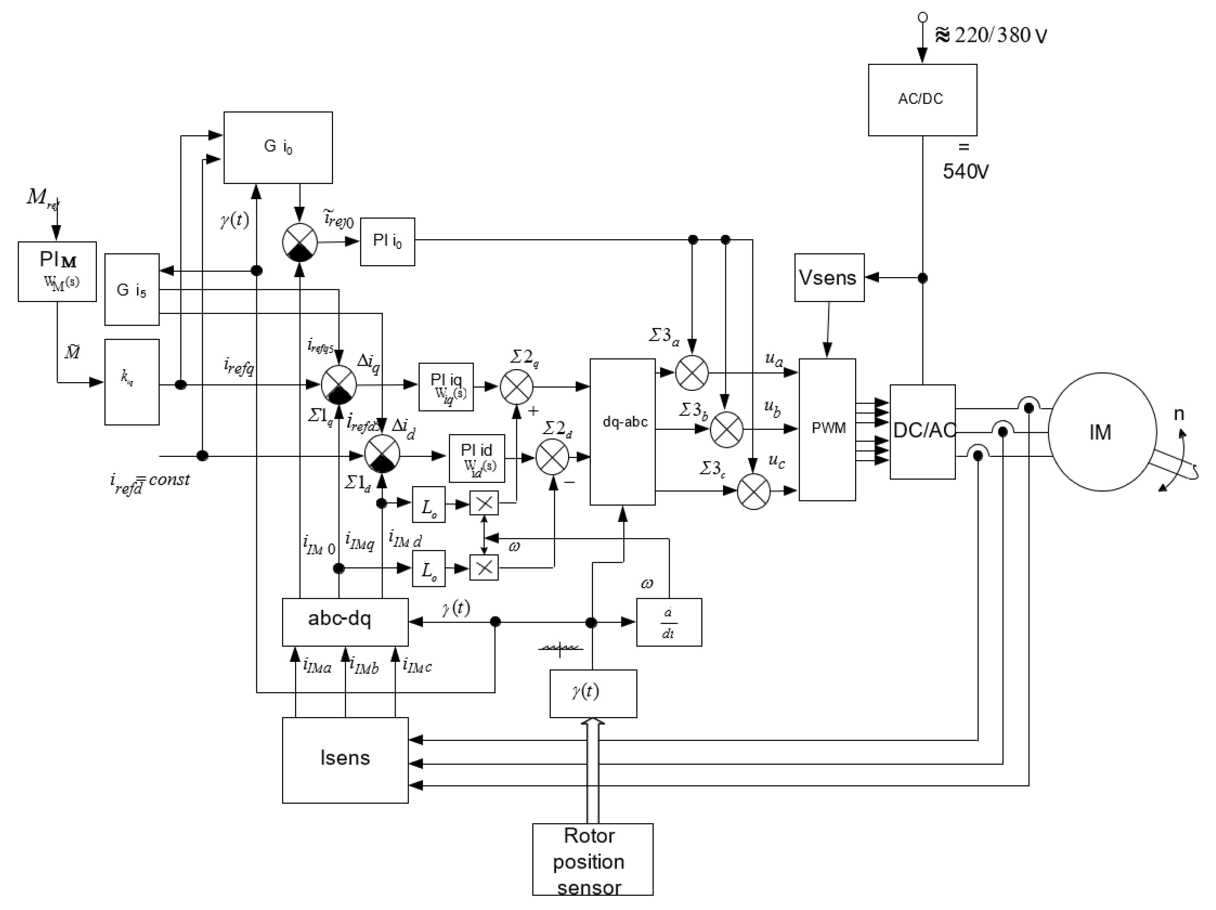
Figure 5 shows a possible algorithm of controlling an electric drive using a voltage inverter (VI), in which the torque of the electric motor operating at maximum speed is regulated. The algorithm is based on the ideas of work [45].
To ensure the required ratio between the fundamental and higher time harmonics of the current, negative feedbacks on the motor currents are used. In this case, in the rotating coordinate system, a signal is set by the first and fifth harmonics, and the assignment for the 5th harmonic is determined by the ratio
where , are signals for setting the orthogonal current components in the first harmonic; is the instantaneous value of the phase of the VI output voltage that is set using the rotor position sensor (RPS).
The shape of the assignment total signals along the orthogonal axes is shown in Figure 6.
Here
The signals of the third harmonic form a zero sequence and are therefore formed in the “A-B-C” axes according to the relation
where .
To obtain astatic regulation of the fundamental harmonic of the electric motor currents, PI controllers are used with transfer characteristics of the form:
The transfer characteristic itself in the torque control channel (TR) in the general case has the form
In order to ensure the dependence of the orthogonal components of the electric motor current on the magnitude of the torque, the and links were introduced. The nature of the dependence of these coefficients on the magnitude of the moment is shown in Figure 5.
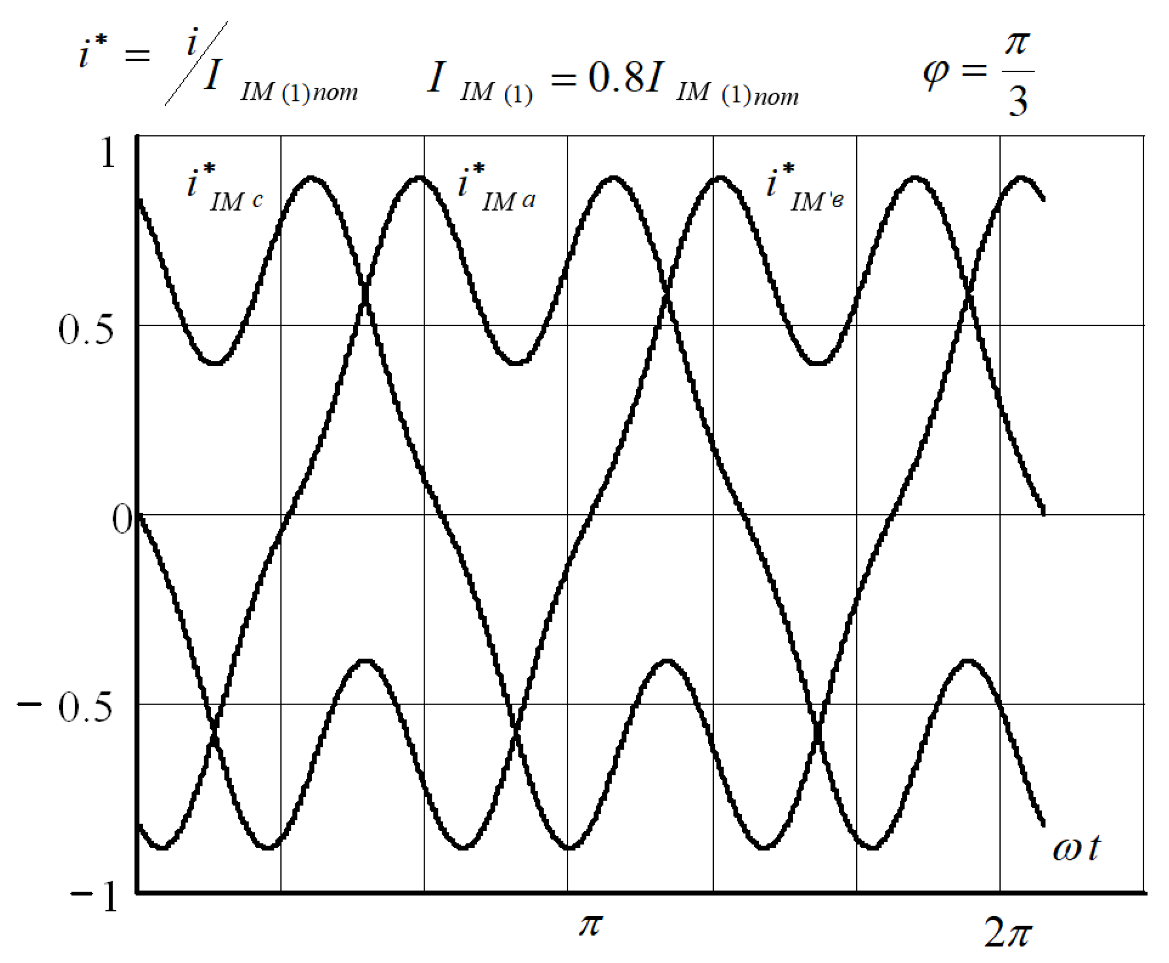
As a result of using the proposed algorithms, the shape of the resulting current in the motor phases has a form close to that shown in Figure 7.
The forced formation of the third and fifth time harmonics, alongside the organization of a no-current pause near the point of transition of the function i*IMa through zero (about 60 degrees), made it possible at the same current amplitude to increase the torque by 27% with a simultaneous decrease in losses by 18%.
4. Analysis
The equations for own and mutual inductances for the mathematical model (Figure 4) are similar to those derived earlier in [47].
To derive the equations of stress and moment, we will use the modified Rademacher functions, the basic concepts of which, as well as the methods of calculating inductances with their help, are set forth in [49]. After carrying out the necessary mathematical operations, the expressions for own and mutual (with respect to the “excitation winding”) inductances will be obtained in the following form:
Here: m = 3, 5, 7, … is the number of phases; k = 1, 2, 3, … is a positive integer.
Having performed transformations using the method of symmetric components and assuming for the steady-state mode of operation that the operator p is equal to zero, and , we obtain:
Equations (13) and (14) are derived for the case when instead of permanent magnets, a winding with the number of turns develops a radial excitation flux. If the machine uses magnets, then flux linkage is considered as .
5. Results
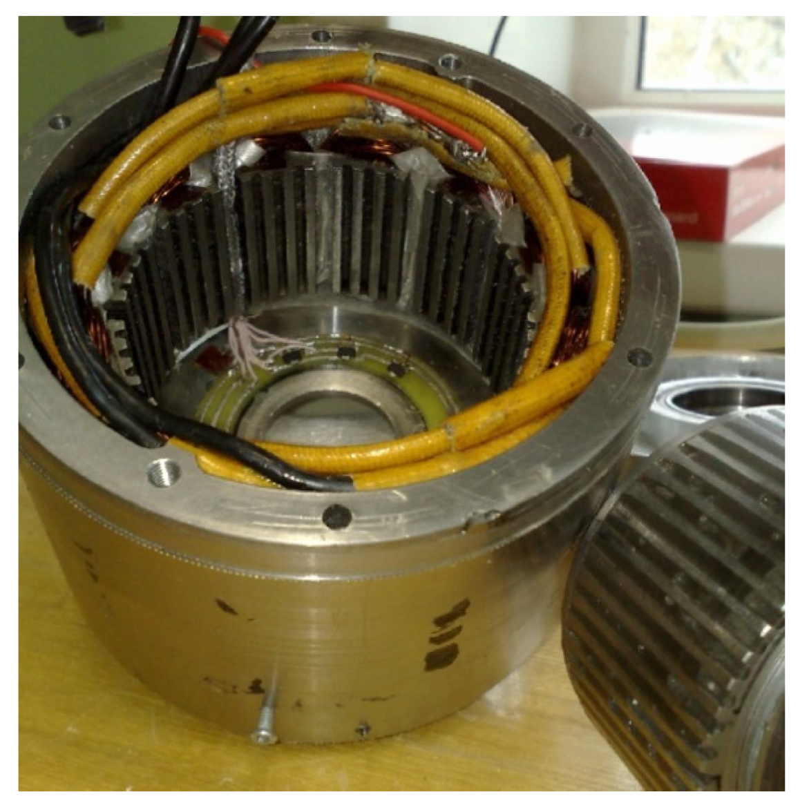
The above studies made it possible to design and to manufacture a high-torque inductor-type electric motor intended for operation as part of shut-off valves (Figure 8). The function was proposed as the optimality criterion in the calculation, where P is the electrical losses in the windings, and the constraints are the dimensions of the electric machine.
This study can be developed in the direction of simplifying the circuit, which will provide a minimum number of elements. This leads to the use of the maximum torque, and the solution is to bring the control system with a circuit on the limit switches.
Below there are the main parameters of the electric mechanism that includes an inductor motor and a planetary mechanical transmission, obtained in the course of experimental research:
- Rated torque-32 Nm;
- Maximum torque-64 Nm;
- Nominal electrical losses-35 W;
- Maximum electrical losses at start-up-350 W;
- Maximum power consumption-600 W;
- Rated frequency of rotation of the output shaft of the engine-60 rpm;
- Maximum rotational speed of the engine output shaft-130 rpm;
- Outside length of the electric mechanism-100 mm;
- The outer diameter of the electric mechanism-126 mm;
- Gear ratio-4.95;
- Total weight-4.3 kg.
In the experiment, the frequency-current method of motor control using 3, 5 harmonics was used. With this method, it was possible to achieve an increase in torque of 20%. To protect the prototype, the IP 54 protection class was used, since an experiment was carried out.
The maximum divergence between the experimental and calculated data is less than 7%. The largest calculation error was recorded when the value of the maximum torque was determined.
Author Contributions
Conceptualization, D.K. and N.U.; methodology, D.K.; validation, A.V.U.; formal analysis, N.U.; resources, A.V.U.; writing—original draft preparation, D.K. and A.M.; writing—review and editing, A.V.U. and A.M.; supervision, D.K.; project administration, D.K. All authors have read and agreed to the published version of the manuscript.
Funding
This research was funded by grant of the Russian Federation President according to the research project No. MK-2204.2020.8.
Data Availability Statement
The data presented in this study are available on request from the corresponding author. The data are not publicly available due to privacy issues.
Conflicts of Interest
The authors declare no conflict of interest.
References
- Krušelja, D.; Sumina, D. Modified predictive torque control method of induction machines for torque ripple reduction. Automatika 2019, 60, 227–238. [Google Scholar] [CrossRef]
- Nash, J.N. Direct torque control, induction motor vector control without an encoder. IEEE Trans. Ind. Appl. 1997, 33, 333–341. [Google Scholar] [CrossRef]
- Casadei, D.; Profumo, F.; Serra, G. FOC and DTC: Two viable schemes for induction motors torque control. IEEE Trans. Power Electron. 2002, 17, 779–787. [Google Scholar] [CrossRef] [Green Version]
- Depenbrock, M. Direkte Selbstregelung (DSR) für hochdynamische Drehfeldantriebe mit Stromrichter-speisung. Etz-Archiv 1985, 7, 211–218. [Google Scholar]
- Depenbrock, M. Direct self-control (DSC) of inverterfed induction machine. IEEE Trans. Power Electron. 1988, 3, 420–429. [Google Scholar] [CrossRef]
- Takahashi, I.; Noguchi, T. A new quick-response and high-efficiency control strategy of an induction motor. IEEE Trans. Ind. Appl. 1986, IA-22, 820–827. [Google Scholar] [CrossRef]
- Tiitinen, P.; Pohjalainen, P.; Lalu, J. The next generation motor control method: Direct torque control (DTC). Eur. Power Electr. Drives J. 1995, 5, 14–18. [Google Scholar]
- Sutikno, T.; Idris, N.R.N. A review of direct torque control of induction motors for sustainable reliability and energy efficient drives. Renew. Sustain. Energy Rev. 2014, 32, 548–558. [Google Scholar] [CrossRef]
- Kumar, R.H.; Iqbal, A.; Lenin, N.C. Review of recent advancements of direct torque control in induction motor drives—A decade of progress. IET Power Electron. 2018, 11, 1–15. [Google Scholar] [CrossRef]
- Cortes, P.; Kaztnierkowski, M.P.; Kennel, R.M.; Quevedo, D.E.; Rodriguez, J. Predictive control in power electronics and drives. IEEE Trans. Ind. Electron. 2008, 55, 4312–4324. [Google Scholar] [CrossRef]
- Kouro, S.; Cortes, P.; Vargas, R.; Ammann, U.; Rodriguez, J. Model predictive control—a simple and powerful method to control power converters. IEEE Trans. Ind. Electron. 2009, 56, 1826–1838. [Google Scholar] [CrossRef]
- Bariša, T.; Ileš, Š.; Sumina, D.; Matuško, J. Model predictive direct current control of a permanent magnet synchronous generator based on Flexible Lyapunov function considering converter dead time. IEEE Trans. Ind. Appl. 2018, 54, 2899–2912. [Google Scholar] [CrossRef]
- Kuoro, S.; Perez, M.; Rodríguez, J.; Llor, A.; Young, H. Model predictive control: MPC’s Role in the Evolution of power electronics. IEEE Ind. Electron. Mag. 2015, 9, 8–21. [Google Scholar] [CrossRef]
- Vazquez, S.; Rodriguez, J.; Rivera, M.; Franquelo, L.G.; Norambuena, M. Model predictive control for power converters and drives: Advances and Trends. IEEE Trans. Ind. Electron. 2017, 64, 935–947. [Google Scholar] [CrossRef] [Green Version]
- Wang, F.; Davari, S.A.; Chen, Z.; Zhang, Z.; Khaburi, D.A.; Rodrieguez, J.; Kennel, R. Finite control set model predictive control of induction machine with a robust adaptive observer. IEEE Trans. Ind. Electron. 2017, 64, 2631–2641. [Google Scholar] [CrossRef]
- Zhang, Y.; Yang, H. Two-vector-based model predictive torque control without weighting factors for induction motor drives. IEEE Trans. Power Electron. 2016, 31, 381–1390. [Google Scholar] [CrossRef]
- Nikzad, M.R.; Asaei, B.; Ahmadi, S.O. Discrete dutycycle-control method for direct torque control of induction motor drives with model predictive solution. IEEE Trans. Power Electron. 2018, 33, 2317–2329. [Google Scholar] [CrossRef]
- Cortés, P.; Kuoro, S.; La Rocca, B.; Vargas, R.; Rodríguez, J.; Leon, J.I.; Vazquez, S.; Franquelo, L.G. Guidelines for weighting factors adjustment in finite state model predictive control of power converters and drives. In Proceedings of the IEEE Conference Industrial Technology, Gippsland, Australia, 10–13 February 2009; pp. 1–7. [Google Scholar]
- Sabir, A.; Ibrir, S. Induction motor speed control using reduced-order model. Automatika 2018, 59, 274–285. [Google Scholar] [CrossRef]
- Fekih, A.; Chowdhury, F.N. On nonlinear control of induction motors: Comparison of two approaches. In Proceedings of the 2004 American Control Conference, Boston, MA, USA, 30 June–2 July 2004; IEEE: Piscataway, NJ, USA, 2004; Volume 1, pp. 1135–1140. [Google Scholar]
- Barambones, O.; Alkorta, P. Vector control for induction motor drives based on adaptive variable structure control algorithm. Asian J. Control 2010, 12, 640–649. [Google Scholar] [CrossRef]
- Retière, N.; Foggia, A.; Roye, D.; Mannevy, P. Deep-bar induction motor model for large transient analysis under saturated conditions. In Proceedings of the 1997 IEEE International Electric Machines and Drives Conference Record, Milwaukee, WI, USA, 18–21 May 1997; IEEE: Piscataway, NJ, USA, 1997. [Google Scholar]
- Binga, L.; Shib, L.; Teng, L. Duty ratio modulation direct torque control of brushless doubly-fed machines. Automatika 2017, 58, 479–486. [Google Scholar] [CrossRef] [Green Version]
- Jerčić, T.; Ileš, Š.; Žarko, D. Constrained field-oriented control of permanent magnet synchronous machine with field-weakening utilizing a reference governor. Automatika 2017, 58, 439–449. [Google Scholar] [CrossRef] [Green Version]
- Lee, J.; Nam, K.; Choi, S.; Kwon, S. A lookup table based loss minimizing control for FCEV permanent magnet synchronous motors. In Proceedings of the Vehicle Power and Propulsion Conference, Arlington, TX, USA, 9–12 September 2007; VPPC 2007. IEEE: Piscataway, NJ, USA, 2007; pp. 175–179. [Google Scholar]
- Jung, S.Y.; Hong, J.; Nam, K. Current minimizing torque control of the IPMSM using Ferrari’s method. IEEE Trans. Power Electron. 2013, 28, 5603–5617. [Google Scholar] [CrossRef]
- Cao, M. Online loss minimization control of IPMSM for electric scooters. In Proceedings of the Power Electronics Conference (IPEC), 2010 International, Sapporo, Japan, 21–24 June 2010; IEEE: Piscataway, NJ, USA, 2010; pp. 1388–1392. [Google Scholar]
- Uddin, M.N.; Zou, H.; Azevedo, F. Online loss-minimization-based adaptive flux observer for direct torque and flux control of PMSM drive. IEEE Trans. Ind. Appl. 2016, 52, 425–431. [Google Scholar] [CrossRef]
- Qi, Z.; Shi, Q.; Zhang, H. Tuning of Digital PID Controllers Using Particle Swarm Optimization Algorithm for a CAN-Based DC Motor Subject to Stochastic Delays. IEEE Trans. Ind. Electron. 2019, 67, 5637–5646. [Google Scholar] [CrossRef]
- Chen, J.; Shuai, Z.; Zhang, H.; Zhao, W. Path Following Control of Autonomous Four-Wheel-Independent-Drive Electric Vehicles via Second-Order Sliding Mode and Nonlinear Disturbance Observer Techniques. IEEE Trans. Ind. Electron. 2020, 68, 2460–2469. [Google Scholar] [CrossRef]
- Ćalasan, P. An invertible dependence of the speed and time of the induction machine during no-load direct start-up. Automatika 2019, 61, 141–149. [Google Scholar] [CrossRef] [Green Version]
- Aree, P. Precise analytical formula for starting time calculation of medium- and high-voltage induction motors under conventional starter methods. Electr. Eng. 2018, 100, 1195–1203. [Google Scholar] [CrossRef]
- Calasan, M. Analytical solution for no-load induction machine speed calculation during direct start-up. Int. Trans. Electr. Energy Syst. 2019, 29, e2777. [Google Scholar] [CrossRef]
- Solveson, M.G.; Mirafzal, B.; Demerdash, N.A.O. Soft-started induction motor modeling and heating issues for different starting profiles using a flux linkage ABC frame of reference. IEEE Trans. Ind. Appl. 2006, 42, 973–982. [Google Scholar] [CrossRef]
- Badr, M.A.; Abdel-Halim, M.A.; Alolah, A.I. A nonconven-tional method for fast starting of three phase wound-rotor induction motors. IEEE Trans. Energy Convers. 1996, 11, 701–707. [Google Scholar] [CrossRef]
- Pillay, K.; Nour, M.; Yang, K.H.; Harun, D.D.; Haw, L.K. Assessment and comparison of conventional motor starters and modern power electronic drives for induction motor starting characteristics. IEEE Symp. Ind. Electron. Appl. 2009, 2, 584–589. [Google Scholar]
- Čeřovský, Z.; Lev, M. Permanent Magnet Synchronous Machine Parameters Identification for Load Characteristics Calculation. Automatika 2015, 56, 217–225. [Google Scholar] [CrossRef] [Green Version]
- Chekhov, R.F. Official Site of the Closed Joint Stock Company Energomash. Available online: www.zavodchzem.ru (accessed on 21 September 2021).
- Calabrese, D.; Tricarico, G.; Brescia, E.; Cascella, G.L.; Monopoli, V.G.; Cupertino, F. Variable Structure Control of a Small Ducted Wind Turbine in the Whole Wind Speed Range Using a Luenberger Observer. Energies 2020, 13, 4647. [Google Scholar] [CrossRef]
- Brescia, E.; Palmieri, M.; Cascella, G.L.; Cupertino, F. Optimal Tooth Tips Design for Cogging Torque Suppression of Permanent Magnet Machines with a Segmented Stator Core. In Proceedings of the 2020 International Conference on Electrical Machines (ICEM), Gothenburg, Sweden, 23–26 August 2020; pp. 1930–1936. [Google Scholar] [CrossRef]
- Brescia, E.; Costantino, D.; Massenio, P.R.; Monopoli, V.G.; Cupertino, F.; Cascella, G.L. A Design Method for the Cogging Torque Minimization of Permanent Magnet Machines with a Segmented Stator Core Based on ANN Surrogate Models. Energies 2021, 14, 1880. [Google Scholar] [CrossRef]
- Antonov, A.S.; Artamonov, B.A.; Korobkov, B.M. Planetary Gears//Tank.-M.: Military Publishing, 1954; pp. 422–607. Available online: https://www.preprints.org/manuscript/202110.0189/download/final_file (accessed on 21 September 2021).
- Kaluzhskii, D.L.; Makarov, D.V.; Mekhtiev, A.D. Inductor Motor with Axial Excitation Flux. In Proceedings of the 17th International Conference of Young Specialists on Micro/Nanotechnologies and Electron Devices (EDM-2016), Erlagol, Russia, 30 June–4 July 2016; pp. 503–506. [Google Scholar]
- Veselovsky, O.N.; Kalushski, D.L. Equations of Electrical Equilibrium and Torque of Synchronous and Asynchronous Motors with Discretely Distributed Windings. Electricity 2000, 5, 31–36. Available online: https://www.elibrary.ru/item.asp?id=34917727 (accessed on 21 September 2021).
- Kalushski, D.L.; Strizhkov, A.M.; Galimzyanov, A.T. Comparative Analysis of High-Torque Engines. On Sat. Scientific. Works of the City of Yekaterinburg, FGAOU VPO UrFu Named after B, N. Yeltsin 2011; 329p. Available online: http://www.rudocs.exdat.com/docs/index-49797.html (accessed on 21 September 2021).
- A.C. No. 1481875 USSR. Synchronous Electric Motor/Zhulovyan, V.V.; Geraskina, N.M.; Kalushski, D.L.; Novikov, P.A.; Markov, Y.u.L.; Kutuzov, E.I. Bul. No. 19, 1989. Available online: https://patents.su/3-1481875-sinkhronnyjj-ehlektrodvigatel.html (accessed on 21 September 2021).
- Kalushski, D.L.; Strizhkov, A.M.; Kharitonov, S.A. Equations of Electrical Equilibrium and Torque of a Reactive Inductor Motor. Electricity 2010, 5, 43–48. Available online: https://www.elibrary.ru/item.asp?id=13519707 (accessed on 21 September 2021).
- Permanent Magnet Synchronous Inductor Motor/Kalushski, D.L.; Shepherds, V.V.; Ponds, N.M. Utility Model Patent No. 125414 Dated 05.06.12. Available online: https://new.fips.ru/Archive/PAT/2013FULL/2013.02.27/DOC/RUNWU1/000/000/000/125/414/DOCUMENT.PDF (accessed on 21 September 2021).
- Kalushski, D.L.; Strizhkov, A.M.; Galimzyanov, A.T. Equations of Electrical Equilibrium and Torque of a Two-Phase Inductor Motor. Electricity 2010, 8, 59–63. Available online: https://www.elibrary.ru/item.asp?id=15056054 (accessed on 21 September 2021).
Figure 1.
Graphic-analytical calculation of the field.

Figure 2.
Electric motor design.

Figure 3.
Determination of the magnesium conductivity of the air gap with a fixed position of the rotor.
Figure 3.
Determination of the magnesium conductivity of the air gap with a fixed position of the rotor.

Figure 4.
Mathematical analogue of a real machine.

Figure 5.
Algorithm of controlling an electric drive using a voltage inverter (VI).

Figure 6.
The shape of the assignment total signals along the orthogonal axes.

Figure 7.
The shape of the resulting current in the motor phases.

Figure 8.
A high-torque inductor-type electric motor.

Publisher’s Note: MDPI stays neutral with regard to jurisdictional claims in published maps and institutional affiliations. |
© 2021 by the authors. Licensee MDPI, Basel, Switzerland. This article is an open access article distributed under the terms and conditions of the Creative Commons Attribution (CC BY) license (https://creativecommons.org/licenses/by/4.0/).
Share and Cite
MDPI and ACS Style
Udovichenko, A.V.; Kaluzhskij, D.; Uvarov, N.; Mekhtiyev, A. Electric Motors for Variable-Speed Drive of Lock Valves. Electronics 2021, 10, 2727. https://0-doi-org.brum.beds.ac.uk/10.3390/electronics10212727
AMA Style
Udovichenko AV, Kaluzhskij D, Uvarov N, Mekhtiyev A. Electric Motors for Variable-Speed Drive of Lock Valves. Electronics. 2021; 10(21):2727. https://0-doi-org.brum.beds.ac.uk/10.3390/electronics10212727
Chicago/Turabian StyleUdovichenko, Aleksey V., Dmitri Kaluzhskij, Nikita Uvarov, and Ali Mekhtiyev. 2021. "Electric Motors for Variable-Speed Drive of Lock Valves" Electronics 10, no. 21: 2727. https://0-doi-org.brum.beds.ac.uk/10.3390/electronics10212727
Note that from the first issue of 2016, this journal uses article numbers instead of page numbers. See further details here.