
On Coding and Decoding Reconfigurable Radiation Pattern Modulation Symbols


Computer, Electrical, and Mathematical Science and Engineering (CEMSE) Division, King Abdullah University of Science and Technology (KAUST), Thuwal 23955-6900, Saudi Arabia
*
Author to whom correspondence should be addressed.
Electronics 2021, 10(5), 614; https://0-doi-org.brum.beds.ac.uk/10.3390/electronics10050614
Submission received: 25 January 2021
/
Revised: 23 February 2021
/
Accepted: 28 February 2021
/
Published: 6 March 2021
(This article belongs to the Special Issue Innovative Technologies in Telecommunication)
Abstract
:In this paper, we propose the theoretical framework for a reconfigurable radiation pattern modulation (RRPM) scheme, which is reminiscent of the index modulation technique. In the proposed scheme, information is encoded using far-field radiation patterns generated by a set of programmable radiating elements. A considerable effort has been invested to allow for high transmission of the reconfigurable radiation pattern symbols; yet, the receiving system has received little attention and has always been considered ideal. Depending on the number of receivers and their respective positions, two variables are considered here for data transmission: the sampling resolution and the fraction of the covered space by the receiving antennas. Hence, we quantitatively investigate their effect on the bit-error-rate (BER) by making use of a limited number of measurements that approximate the behavior of the system under real-field conditions.
1. Introduction
We are in a time of instant communication. Users require ever-increasing speed, power, and availability. Communication systems have remained almost unchanged since the invention of the superheterodyne receiver [1] and the introduction of coding [2]. Artificial intelligence, remote surgeries, virtual reality, autonomous cars, the increased need for remote working due in particular to healthcare issues (e.g., the COVID-19 pandemic), and the internet of things (IoT) are among the avenues that revolutionize the technology of this century. Techniques such as enhanced multiple-input and multiple-output (MIMO) systems, millimeter-wave (mmWave), and controllable electromagnetic environments are proposed to be standardized in the coming years. While MIMO systems have become essential parts of almost all modern communication systems [3,4], there are scenarios where the number of used antennas cannot be massive. New modulation methodologies need to be implemented to minimize the number of components while maximizing the capacity of the communication system. The index modulation (IM) technique, which maximizes the amount of information that is extracted from the building blocks of the communication chain, is a strong candidate for the communication revolution due to its hardware simplicity [5,6,7]. IM has been investigated since the beginning of the millennium [8,9,10,11,12], attracting even more attention in recent years. This technique focuses on the states of the building blocks rather than the classical parameters from the signal, e.g., amplitude, phase, and/or frequency. IM schemes can alternate the ON and OFF states of the communication blocks to encode data; antennas, RF diodes, RF mirrors, signal powers, sub-carriers, modulation types, and loads are typical examples of communication blocks that can be used as IM [13,14,15,16]. In the same vein, one of the most promising types of IM schemes is reconfigurable radiation patterns modulation (RRPM) [17,18]; the information bits are encoded onto the radiation patterns of reconfigurable antenna arrays, programmable metasurfaces [19,20], or reconfigurable antennas [21,22]. Most of the current effort has focused on the device that emits the radiation patterns rather than measuring the emitted pattern.
In this work, we propose a methodology for characterizing RRPM systems under realistic conditions. In fact, in the current literature, radiation patterns from multiple sources (reconfigurable-antennas, metasurfaces) are measured using an anechoic chamber with a turntable surrounded by a high number of antennas that results in a high-resolution reconstruction of the transmitted symbols. In this paper, we assume a realistic scenario instead, with a limited number of receiving antennas that partially reconstruct the radiation symbols. For instance, one receiving antenna is needed for measuring a point in the far-field; a low density of receiving antennas will result in a sparse symbol reconstruction. Under these restrictions of direction and receiving antennas, the transmitted symbols must be optimized in order to reduce the probability of error. A methodology for selecting the radiation symbols with the minimum probability of error to be transmitted is developed for a realistic scenario. The symbols are transmitted over a noisy simulated channel with a minimal number of receiving antennas, positioned at specific fractions of the study domain (spherical coordinates). Afterward, the bit-error-rate (BER) is calculated and quantified for each case as the leading figure of merit.
The remainder of this paper is organized as follows: Section 2 gives the theoretical background of this work. Section 3 introduces the algorithm for smart radiation pattern symbol selection and details the BER Monte-Carlo simulations for different scenarios of measured radiation patterns. Section 4 gives a short discussion and some concluding remarks on the results obtained.
2. Materials and Methods
This section describes the implementation model of the proposed coding/decoding modulation using a reconfigurable radiation device.
2.1. Radiation Pattern Symbols
An antenna formed by multi-elements is known as an array. Antenna arrays are mostly used to direct radiated power towards the desired direction with a high gain. The number of elements, the geometrical configuration, current, amplitude, and phase will influence the behavior of the whole system. The discrete sources radiate individually, but the total radiation pattern is built up by the coherent addition of each element. The relative amplitude and phase of the excitation currents on each element will determine the behavior of the resulting field [23]. The array factor () is the far-field radiation intensity, and is obtained for an array of elements located at the position as
where is the direction (normal) unit vector to , is the complex excitation coefficient, is the added phase component, and is the wavenumber. The accounts for the variation of the power radiated as a function of and (components of in a spherical coordinate system). In the far-field, the radial component of the electric field is zero; receiving antennas have thus only the requirement of being further than where is the largest dimension of the antenna [19]. A reconfigurable antenna array is an antenna with a tunable [24,25,26,27]. Without loss of generality, a straightforward model of reconfigurable antennas is used in this work: a point source isotropic antenna with a tunable phase. For an isotropic antenna, the radiation intensity is constant in all directions. The only difference between each antenna element will be their relative position in the space and the added phase component.
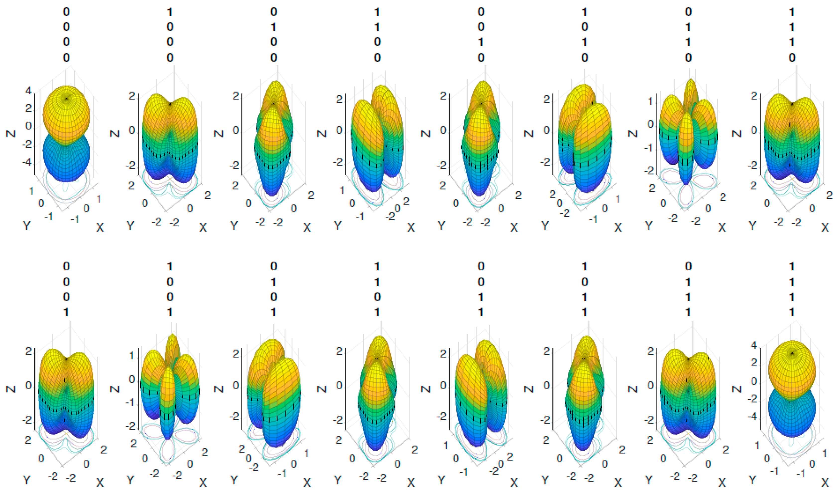
As a first case, four antennas are collocated at a wavelength-normalized () at the positions and (See Figure 1). Each antenna introduces a variable phase shift of or . Sixteen different combinations are obtained for this array. Considering the whole space, and measuring the radiated power gain (in spherical coordinates) at a considerable number of points, the sixteen combinations are shown in Figure 2. As shown in Figure 2, the radiation patterns have space symmetry for the upper and lower halves of the space; however, this is not the case for all radiation systems, which can be the case for complex reconfigurable arrays or metasurfaces. The purpose of an RRPM is to reconstruct the radiated symbols to decode information bits. Depending on the configuration of the receiver setup, the reconstruction of the radiation pattern may be affected. Two variables profoundly alter the measurement of the radiation symbols, i.e., the resolution used and the fraction of the space measured.
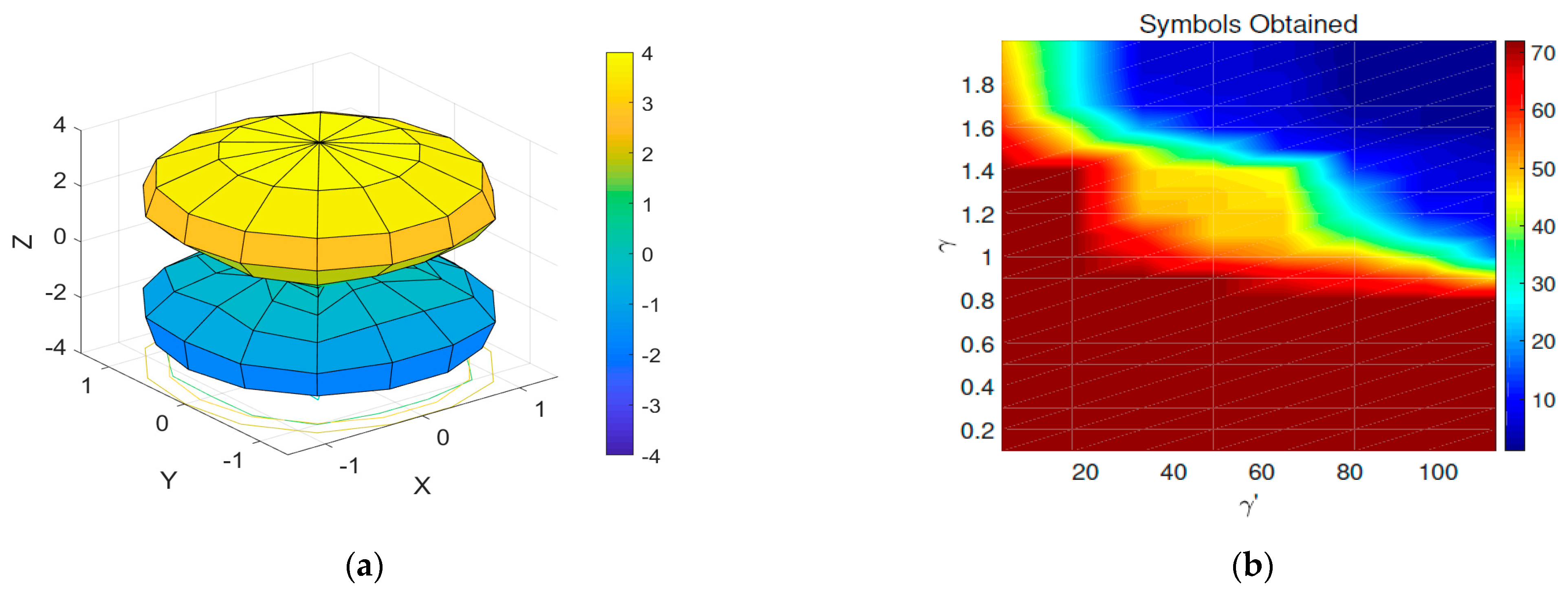
Resolution: The resolution takes into account the positions in and that will be measured. When , positions are measured in and positions are measured in , leading to a total of measurements. Under realistic circumstances, one static antenna will measure one point; a total number of antennas are thus required. A high resolution requires an excessive number of antennas. The degradation of the radiation pattern symbols due to a low resolution is depicted in Figure 3a.
Covered region: There are not many useful applications for this modulation scheme if the entire radiation pattern has to be measured. Under realistic conditions of operation, only certain parts of the total radiation pattern may be used to encode information. The radiated symbol will be measured partially in the direction of a user with a limited number of antennas.
2.2. Symbol Selection
As shown in Figure 2, the full spherical space is considered () with a high resolution () to reconstruct the radiation symbols. By inspection, only six out of the sixteen states from Figure 2 are unique. The level of uniqueness is quantified by the degree of linear independence or orthogonality between each pair of symbols. To quantify this, we consider a procedure to determine the linear independence of radiation pattern symbols according to the number of elements of the array, their position in the plane, and the phase shift each element introduces. The linear independence will be determined using the Euclidean distance between a pair of radiation patterns as a figure of merit. A higher distance will represent a higher level of independence, reducing the risk of error in a noisy channel. Each radiation pattern is a point in the Euclidean space, i.e., ; the Euclidean distance is then defined as
where and denote the array factors of the two considered radiation patterns. Communication systems are, in fact, noisy, and in this work, the simplest model accounting for noise is assumed, i.e., additive white Gaussian noise (AWGN) [28]. Rayleigh models are not considered in this case, under the assumption that the system is static. Selecting highly independent symbols reduces thus the probability of the symbol being corrupted by additive noise. For a set of total radiation patterns, we propose Algorithm 1 as a method for selecting the symbols with a higher level of independence.
| Algorithm 1: Defining orthogonality for reconfigurable radiation patterns. |
| Result: A set of orthogonal symbols that minimize the BER is defined. antennas array. is defined. between each radiation pattern pair is calculated. between symbols is chosen. First threshold (): for i = 1: RP do for do if then else end end end end for do then symbols can be transmitted. end end Remove redundant symbols if required. |
Two thresholds are used in Algorithm 1. The first threshold refers to the minimum distance between a pair of radiation patterns that can be considered large enough to avoid symbol corruption when noise is added. The second threshold refers to the number of times a symbol satisfies when the whole set is considered. The threshold selection represents the main parameter to determine the vulnerability of the communication scheme. Using and , the algorithm identifies four symbols like the ones that satisfy these two conditions. Increasing to 1.3 leads to a reduction of the information bits by half. More stringent thresholds result in fewer numbers of radiation patterns highly independent and less likely to be corrupted by noise. The most straightforward way to increase the number of symbols while having high thresholds is to increase the number of point source antennas. As an example, the system can be expanded to an eight-antenna configuration positioned in the wavelength-normalized XY-plane at Assuming the same phase conditions as in the previous case, and , the number of possible phase combinations for the eight antennas assuming that each one can be tuned independently is . As was the case before, not all the 256 sets of symbols will be unique. Considering a realistic resolution for measuring the radiation patterns in the whole spherical domain (), the number of orthogonal symbols is extracted for a variable The number of orthogonal symbols given when and are swept is depicted in Figure 3b; from the 256 combinations, 72 are unique. Increasing the threshold reduces the number of transmitted bits per period; however, the probability of error is diminished for noisy channels.
3. Results
In any digital communication scheme, the BER is the standard figure of merit for quantifying its performance. Different computational methods are used to calculate the BER, and the Monte-Carlo simulation is by far the most popular technique among these [29,30]. The Monte-Carlo simulation uses a deterministic approach to calculate the BER. The usual approach consists of producing pseudo-arbitrary bits, simulating the transmission and detection of these bits, and finally counting the number of mismatches in the output. The symbols are demodulated using a maximum-likelihood (ML) demodulation, and the number of mismatches between the input and output will be counted as errors. The BER is then
3.1. BER for AWGN Wireless Channel
Let us consider a communication system that is transmitting radiation pattern symbols over an AWGN channel. Let be an orthogonal radiation pattern symbol from the RP number of radiation patterns. During each period bits are transmitted. For each period, additive noise will be added to the transmitted signal, i.e.,
where is the radiation pattern with the noise added. Afterward, Algorithm 2 is used to decode the received into the demodulated radiation pattern. Whenever , an error will be counted.
| Algorithm 2: Maximum likelihood detector. |
| Result: ML demodulator for RRPM symbols. For a radiation pattern symbols set of length RP, for do . end . |
In this contribution, RRPM is an analog of the space-shift-keying spatial-modulation [31], where the only symbols transmitted are the radiation patterns. However, this methodology can also be applied for composite systems where an M-ary digitally modulated signal is used. A Monte-Carlo simulation with random binary bits using the four antennas array from Section 2 is made under different system conditions. A maximum number of errors is chosen, as stated in Ref. [30]. The effect of the resolution and the fraction of the space considered for the measurement is investigated.
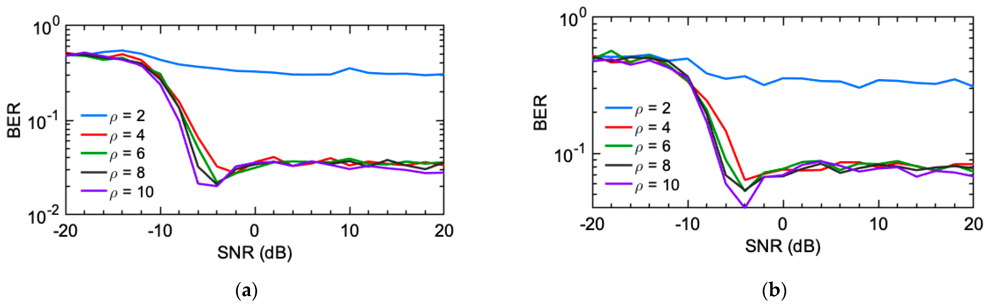
For a realistic characterization, a low resolution is required to simulate scenarios outside of an anechoic chamber. The resolutions considered for the simulation are . A resolution of 10 restricts the number of measured points to 100, which is still a relatively high number of antennas. Realistic approaches will use resolutions equal to 2 or 4. As a result of the low resolution in comparison to the area of measurement, the radiation patterns will not be precisely plotted when the considered measured spherical space is ample. Three different fractions of the space are evaluated: the typical total radiation space , the upper part , and a minimal fraction . The BER is simulated for a signal to noise ratio (SNR) sweep between −20 dB to 20 dB. For each resolution and fraction of the space measured, Algorithm 1 is used to select the symbols; a fixed and are used.
As is depicted in Figure 4, the resolution, space, and threshold restrictions in multiple orthogonal radiated symbols are shown. In Figure 4, the symbols obtained for and the three considered fractions of the space are shown. The spatial restrictions used for the case of Figure 4a resulted in four different radiation symbols (2 bits), while for the cases considered in Figure 4b,c, only a pair of symbols is obtained for each (1 bit). A proper selection of the resolution and the space considered can lead to a higher number of successfully transmitted bits, as is the case in Figure 4b, where measuring half the space is preferred in terms of the orthogonality between symbols.
The BER results are shown and contrasted in Figure 5. In the three fractions of the space considered, is preferred to operate perfectly under typical SNR values for wireless channels (). Higher resolutions are unnecessary, as can be seen in Figure 5 for the three cases (their effect is almost negligible for normal noise ranges). A resolution of four can be appropriately used if the total radiation space measurement is avoided. Figure 5b shows the best performance when a minimum resolution of two is considered; this is due to the higher Euclidean distance between symbols obtained compared to the other cases. When for Figure 5a,c, the BER results are equivalent. One may expect better performance when a small section of the space is measured with the same resolution as a vast section; however, the space limitation reduces the symbol diversity, lowering thus the distance between them. The proper selection of the resolution and the space measured need to be considered to improve the probability of error.
3.2. Channel Considerations
Simple slow fading and attenuation models can be immediately included in the model using the multiple techniques described in [32]. Figure 6 presents the effect of two channel effects shown for the case considered in Figure 5b. For an arbitrary shadow fading modeled as Gaussian normalized variable , the BER poorly performs as shown in Figure 5a. Even more, a rain attenuation factor can be easily included using, for example, the models given in [33,34]; assuming a 1.5 dB rain attenuation for a specific distance, geographical location, and rain rate, the BER is further deteriorated (Figure 6b). The system operates poorly if an obstruction or attenuation is added when only two symbols are considered, as in the previous case. The system relies entirely on a static collection of symbols, with a high or low degree of orthogonality between them; an obstacle can quickly deteriorate the orthogonality between them. A designer can either increase the symbols’ orthogonality or, preferably, use an adaptable methodology capable of dealing with the sudden changes in the wireless channel. Once the possible applications for this communication technique are given, specific models can be created to account for each of the different wireless channels’ particular difficulties.
4. Conclusions
IM is an elegant approach to maximizing the number of bits transmitted through a reconfigurable radiation pattern device. An IM-based methodology for selecting suitable reconfigurable radiation patterns for transmitting binary information is presented in this paper. Radiation pattern symbols are used directly to encode information bits. The radiation symbols transmitted are selected according to an algorithm that maximizes the orthogonality between each set of symbols, considering the BER as the leading figure of merit. The portion of covered space and the number of receiving antennas are considered as variables with a high impact on the BER. In this work, we evaluate the effect of the measurement conditions for the first time, giving a reference for the appropriate symbol selection. The impact of the position and density of receiving antennas has a direct effect on the BER depending on the number of bits to be transmitted. Increasing the number of measuring antennas is shown to lead to a lower error probability if a higher density of symbols is encoded, as can be seen in Figure 5. Depending on the orthogonality requirements for a system, the designer can quickly adapt Algorithm 1 to increase or decrease the number of symbols transmitted. The developed methodology can be applied in any kind of reconfigurable radiation device; however, further research has to be done in hybrid systems with reconfigurable antenna arrays and reconfigurable metasurfaces, including multipath propagation and various channel fading models for static and dynamic systems.
Author Contributions
H.B. initiated this project. Conceptualization: S.C., M.F. and L.Z. identified the theoretical constructs and the different elements that represented the phenomenon in academic terms. Validation: S.C. and M.F. conducted the verification and validation such that the system complied with the requirements and specifications according to the intended purpose. Formal Analysis: S.C., M.F., L.Z., H.B., A.M.E. and K.N.S. developed the required theoretical analysis. Resources and funding: K.N.S., H.B. and A.M.E. obtained technological, financial and economic resources. Writing, initial-draft preparations: SC and MF edited the first deliverable draft of the manuscript. Writing, review and editing: M.F., H.B., K.N.S., A.M.E. and L.Z. re-edited the paper and performed proofreading. Supervision: M.F., H.B., A.M.E. and K.N.S. supervised the technical and scientific-quality assurance of the study. All authors have read and agreed to the published version of the manuscript.
Funding
This research received no external funding.
Acknowledgments
The authors are thankful for the technological support of the Computer, Electrical, and Mathematical Science and Engineering (CEMSE) Division of King Abdullah University of Science and Technology (KAUST), Thuwal, Saudi Arabia.
Conflicts of Interest
The authors declare no conflict of interest.
References
- Maas, S. Armstrong and the Superheterodyne: A Historical Look at the Mixer. IEEE Microw. Mag. 2013, 14, 34–39. [Google Scholar] [CrossRef]
- Shannon, C.E. A Mathematical Theory of Communication. Bell Syst. Tech. J. 1948, 27, 379–423. [Google Scholar] [CrossRef] [Green Version]
- Renzo, M.D.; Haas, H.; Ghrayeb, A.; Sugiura, S.; Hanzo, L. Spatial Modulation for Generalized MIMO: Challenges, Opportunities, and Implementation. Proc. IEEE 2014, 102, 56–103. [Google Scholar] [CrossRef]
- Chen, Z.; Sohrabi, F.; Yu, W. Multi-Cell Sparse Activity Detection for Massive Random Access: Massive MIMO Versus Cooperative MIMO. IEEE Trans. Wirel. Commun. 2019, 18, 4060–4074. [Google Scholar] [CrossRef] [Green Version]
- Lai, Y.; Ciou, Y.; Wu, J. Index Modulation Multiple Access. In Proceedings of the 2018 IEEE 29th Annual International Symposium on Personal, Indoor and Mobile Radio Communications (PIMRC), Bologna, Italy, 9–12 September 2018; pp. 1–5. [Google Scholar]
- Basar, E. Index Modulation Techniques for 5G Wireless Networks. IEEE Commun. Mag. 2016, 54, 168–175. [Google Scholar] [CrossRef] [Green Version]
- Basar, E.; Wen, M.; Mesleh, R.; Di Renzo, M.; Xiao, Y.; Haas, H. Index Modulation Techniques for Next-Generation Wireless Networks. IEEE Access 2017, 5, 16693–16746. [Google Scholar] [CrossRef]
- Mesleh, R.Y.; Haas, H.; Sinanovic, S.; Ahn, C.W.; Yun, S. Spatial Modulation. IEEE Trans. Veh. Technol. 2008, 57, 2228–2241. [Google Scholar] [CrossRef]
- Cong, L.; Li, K.; Kot, A.C. On Decision-Feedback Detection of Differential Space-Time Modulation in Continuous Fading. IEEE Trans. Commun. 2004, 52, 1613–1617. [Google Scholar] [CrossRef]
- Alrabadi, O.N.; Kalis, A.; Papadias, C.B.; Prasad, R. Aerial Modulation for High Order PSK Transmission Schemes. In Proceedings of the 2009 1st International Conference on Wireless Communication, Vehicular Technology, Information Theory and Aerospace Electronic Systems Technology, Aalborg, Denmark, 17–20 May 2009; pp. 823–826. [Google Scholar]
- Peel, C.B.; Swindlehurst, A.L. Effective SNR for Space-Time Modulation over a Time-Varying Rician Channel. IEEE Trans. Commun. 2004, 52, 17–23. [Google Scholar] [CrossRef]
- Li, Y.; Xia, X.-G. Constellation Mapping for Space-Time Matrix Modulation with Iterative Demodulation/Decoding. IEEE Trans. Commun. 2005, 53, 764–768. [Google Scholar] [CrossRef]
- Naresh, Y.; Chockalingam, A. On Media-Based Modulation Using RF Mirrors. IEEE Trans. Veh. Technol. 2017, 66, 4967–4983. [Google Scholar] [CrossRef] [Green Version]
- Başar, E.; Panayirci, E.; Uysal, M.; Haas, H. Generalized LED Index Modulation Optical OFDM for MIMO Visible Light Communications Systems. In Proceedings of the 2016 IEEE International Conference on Communications (ICC), Kuala Lumpur, Malaysia, 22–27 May 2016; pp. 1–5. [Google Scholar]
- Zhang, X.; Bie, H.; Ye, Q.; Lei, C.; Tang, X. Dual-Mode Index Modulation Aided OFDM with Constellation Power Allocation and Low-Complexity Detector Design. IEEE Access 2017, 5, 23871–23880. [Google Scholar] [CrossRef]
- Bouida, Z.; El-Sallabi, H.; Ghrayeb, A.; Qaraqe, K.A. Reconfigurable Antenna-Based Space-Shift Keying (SSK) for MIMO Rician Channels. IEEE Trans. Wirel. Commun. 2016, 15, 446–457. [Google Scholar] [CrossRef]
- Gong, S.; Lu, X.; Hoang, D.T.; Niyato, D.; Shu, L.; Kim, D.I.; Liang, Y.-C. Towards Smart Radio Environment for Wireless Communications via Intelligent Reflecting Surfaces: A Comprehensive Survey. arXiv 2019, arXiv:191207794. [Google Scholar]
- Viet, D.N.; Di Renzo, M.; Basavarajappa, V.; Exposito, B.B.; Basterrechea, J.; Phan-Huy, D.-T. Spatial Modulation Based on Reconfigurable Antennas: Performance Evaluation by Using the Prototype of a Reconfigurable Antenna. arXiv 2019, arXiv:190101752. [Google Scholar]
- Cui, T.J.; Liu, S.; Bai, G.D.; Ma, Q. Direct Transmission of Digital Message via Programmable Coding Metasurface. Research 2019, 2019, 584509. [Google Scholar] [CrossRef] [Green Version]
- Basar, E.; Di Renzo, M.; de Rosny, J.; Debbah, M.; Alouini, M.-S.; Zhang, R. Wireless Communications Through Reconfigurable Intelligent Surfaces. arXiv 2019, arXiv:190609490. [Google Scholar] [CrossRef]
- Kokar, Y.; Rachedi, K.; Ourir, A.; de Rosny, J.; Phan-Huy, D.-T.; Prévotet, J.-C.; Hélard, M. Demo Abstract: Spatial Modulation Based Transmission Using a Reconfigurable Antenna. In Proceedings of the IEEE INFOCOM 2019—IEEE Conference on Computer Communications Workshops (INFOCOM WKSHPS), Paris, France, 29 April–2 May 2019; pp. 985–986. [Google Scholar]
- Ourir, A.; Rachedi, K.; Phan-Huy, D.-T.; Leray, C.; de Rosny, J. Compact Reconfigurable Antenna with Radiation Pattern Diversity for Spatial Modulation. In Proceedings of the 2017 11th European Conference on Antennas and Propagation (EUCAP), Paris, France, 19–24 March 2017; pp. 3038–3043. [Google Scholar]
- Balanis, C.A. Antenna Theory: Analysis and Design; Wiley: Hoboken, NJ, USA, 2016. [Google Scholar]
- Jo, E.; Kim, D.; Hur, J.; Kim, D.; Kim, C.; Choi, Y.; Cho, Y.; Kim, C.H.; Park, B.H.; Hyun, S. A Frequency Reconfigurable Slot Dipole Antenna Using Surface PIN Diodes. In Proceedings of the 2017 International Symposium on Antennas and Propagation (ISAP), Phuket, Thailand, 30 October–2 November 2017; pp. 1–2. [Google Scholar]
- Thao, H.T.P.; Son, T.V.; Doai, N.V.; Duc, N.T.; Yem, V.V. A Novel Frequency Reconfigurable Monopole Antenna Using PIN Diode for WLAN/WIMAX Applications. In Proceedings of the 2015 International Conference on Communications, Management and Telecommunications (ComManTel), Da Nang, Vietnam, 28–30 December 2015; pp. 167–171. [Google Scholar]
- CAI, X.; WANG, A.; MA, N.; LENG, W. Novel Radiation Pattern Reconfigurable Antenna with Six Beam Choices. J. China Univ. Posts Telecommun. 2012, 19, 123–128. [Google Scholar] [CrossRef]
- Ali Esmail, B.; Majid, H.A.; Zainal Abidin, Z.; Haimi Dahlan, S.; Himdi, M.; Dewan, R.; Rahim, M.K.A.; Al-Fadhali, N. Reconfigurable Radiation Pattern of Planar Antenna Using Metamaterial for 5G Applications. Materials 2020, 13, 582. [Google Scholar] [CrossRef] [Green Version]
- Proakis, J.G. Digital Communications; McGraw-Hill Series in Electrical and Computer Engineering: Communications and Signal Processing; McGraw-Hill: New York, NY, USA, 2001; ISBN 978-0-07-118183-9. [Google Scholar]
- Renzo, M.D.; Haas, H. Bit Error Probability of SM-MIMO Over Generalized Fading Channels. IEEE Trans. Veh. Technol. 2012, 61, 1124–1144. [Google Scholar] [CrossRef] [Green Version]
- Mazzeo, B.; Rice, M. On Monte-Carlo Simulation of the Bit Error Rate. In Proceedings of the 2011 IEEE International Conference on Communications (ICC), Kyoto, Japan, 5–9 June 2011; pp. 1–5. [Google Scholar]
- Som, P.; Chockalingam, A. Spatial Modulation and Space Shift Keying in Single Carrier Communication. In Proceedings of the 2012 IEEE 23rd International Symposium on Personal, Indoor and Mobile Radio Communications—(PIMRC), Sydney, Australia, 9–12 September 2012; pp. 1962–1967. [Google Scholar]
- Rappaport, T.S. Wireless Communications: Principles and Practice; Prentice Hall: Upper Saddle River, NJ, USA, 2002; ISBN 978-0-13-042232-3. [Google Scholar]
- Raina, M.; Uppal, G. Frequency Dependence of Rain Attenuation Measurements at Microwave Frequencies. IEEE Trans. Antennas Propag. 1984, 32, 185–187. [Google Scholar] [CrossRef]
- Kestwal, M.C.; Joshi, S.; Garia, L.S. Prediction of Rain Attenuation and Impact of Rain in Wave Propagation at Microwave Frequency for Tropical Region (Uttarakhand, India). Int. J. Microw. Sci. Technol. 2014, 2014, 1–6. [Google Scholar] [CrossRef] [Green Version]
Figure 1.
Two by two reconfigurable antenna array in a wavelength-normalized XY-plane.

Figure 2.
Radiation patterns for four antennas located at: , , and with and

Figure 3.
Measuring and coding information bits into radiation patterns. (a) Degraded radiation pattern gain (dBi) reconstruction assuming a limited resolution for symbol 00,000 shown in Figure 2. (b) Orthogonal symbols for an eight-antenna system with versus the parameters and
Figure 3.
Measuring and coding information bits into radiation patterns. (a) Degraded radiation pattern gain (dBi) reconstruction assuming a limited resolution for symbol 00,000 shown in Figure 2. (b) Orthogonal symbols for an eight-antenna system with versus the parameters and

Figure 4.
Optimal symbols for and for the considered space (a) (b) , and (c) .

Figure 5.
Bit-error-rate (BER): (a) (b) . (c) .

Figure 6.
BER (: (a) slow-fading. (b) slow-fading and 1.5 dB of rain attenuation.

Publisher’s Note: MDPI stays neutral with regard to jurisdictional claims in published maps and institutional affiliations. |
© 2021 by the authors. Licensee MDPI, Basel, Switzerland. This article is an open access article distributed under the terms and conditions of the Creative Commons Attribution (CC BY) license (http://creativecommons.org/licenses/by/4.0/).
Share and Cite
MDPI and ACS Style
Celis, S.; Farhat, M.; Zhang, L.; Bagci, H.; Eltawil, A.M.; Salama, K.N. On Coding and Decoding Reconfigurable Radiation Pattern Modulation Symbols. Electronics 2021, 10, 614. https://0-doi-org.brum.beds.ac.uk/10.3390/electronics10050614
AMA Style
Celis S, Farhat M, Zhang L, Bagci H, Eltawil AM, Salama KN. On Coding and Decoding Reconfigurable Radiation Pattern Modulation Symbols. Electronics. 2021; 10(5):614. https://0-doi-org.brum.beds.ac.uk/10.3390/electronics10050614
Chicago/Turabian StyleCelis, Sebastian, Mohamed Farhat, Li Zhang, Hakan Bagci, Ahmed M. Eltawil, and Khaled N. Salama. 2021. "On Coding and Decoding Reconfigurable Radiation Pattern Modulation Symbols" Electronics 10, no. 5: 614. https://0-doi-org.brum.beds.ac.uk/10.3390/electronics10050614
Note that from the first issue of 2016, this journal uses article numbers instead of page numbers. See further details here.