
Distributed Hierarchical Control for Islanded Microgrids Based on Adjustable Power Consensus


School of Information Engineering, Nanchang University, Nanchang 330031, China
*
Author to whom correspondence should be addressed.
Electronics 2022, 11(3), 324; https://0-doi-org.brum.beds.ac.uk/10.3390/electronics11030324
Submission received: 21 December 2021
/
Revised: 14 January 2022
/
Accepted: 18 January 2022
/
Published: 20 January 2022
(This article belongs to the Special Issue Power Electronics Applications in Microgrid and Distributed Generation)
Abstract
:For the problem of power allocation in microgrid hierarchical control, a distributed hierarchical control strategy based on consensus algorithm is proposed. When the load suddenly increases, due to the different adjustable power of different distributed generators (DGs), overcharging and discharging of DGs will result if the increased load is not redistributed. The distributed hierarchical control strategy proposed in this paper defines the proportion between the local increased load and the local adjustable power as the response ratio. With the objective of ensuring that the frequency and voltage of the microgrid can be restored to their rated value, the response ratios of DGs are adjusted by applying the consensus algorithm. Further, the microgrid realizes the reasonable operation of the microgrid by dynamically distributing the increased load in real time. Finally, the feasibility and effectiveness of the proposed strategy is verified by analyzing the stability of the system and building a microgrid simulation model in the Matlab/Simulink simulation platform.
1. Introduction
With the consumption of non-renewable energy and environmental pollution, the global energy crisis is becoming more and more severe [1], and the efficient use of new energy sources has become the trend of social development [2]. Microgrids can make the penetration of renewable energy in the large grid increase, and also improve the power quality and reliability of power supply [3]. Microgrids are mainly composed of distributed generators, energy storage devices, loads, etc., and usually have two working modes: grid-connected and islanding operation. The stable operation of microgrids requires effective and rational control technology, so researchers have paid close attention to this area [4].
In the development of the power system, two control schemes, distributed and centralized, were proposed [5]. Centralized control requires each DG to exchange information with the central controller, the central controller issues commands, and the local control receives the information to be able to make actions, each DG only needs to communicate with the central controller, while no communication is required between the neighbors of the DG [6]. Distributed control requires only local information to be obtained via sparse communication between neighbors for calculation and analysis, and DGs make decisions based on the calculation results to optimize and control the entire grid. Centralized control is prone to face problems such as large computation, single point of failure, and poor scalability, compared to distributed control which has better economy and robustness [7], and has been intensively studied by many scholars recently.
The choice of control structure is important for the stable operation of microgrids, and nowadays, the control and optimization of the grid is mainly achieved by means of hierarchical control [8]. Microgrids are usually divided into three levels of control structure, primary control, secondary control, and tertiary control. Generally, they have different control objectives and timescales. Droop control, as primary control, regulates the frequency and voltage of the microgrid by the obtained power information, but droop control is a differential control and usually requires the introduction of secondary control to eliminate errors [9]. In contrast, tertiary control mainly provides global control of the system to optimize the microgrid and achieve a rational operation of the microgrid.
Traditionally, secondary control is implemented through a central controller [10]. However, with the development of multi-agent systems (MAS), Ref. [11] treats each DG separately as a multi-agent and [12] implements the secondary control of the microgrid through distributed algorithms. The secondary control is mainly implemented by distributed cooperative control for voltage/frequency recovery [13], power sharing [14], and unbalanced voltage compensation [15]. Moreover, the conflict between voltage regulation and reactive power sharing is described in [16], and a distributed average proportional controller is proposed to reduce the voltage deviation and achieve accurate reactive power sharing by adjusting the relative size of the control gain. Furthermore, Ref. [17] proposed an islanded microgrid reactive power sharing method based on consensus control and adaptive virtual impedance control and dynamic consensus to recover the reduced output voltage of each DG due to droop control and increased virtual impedance when addressing the mismatch in reactive power sharing caused by line mismatch. After that, various improvement methods have also been proposed for distributed control of microgrids, including nonlinearity [18], model predictive control [19], and optimal control [20].
However, the global control of the microgrid can not be achieved solely by the secondary control, and the tertiary control is often employed. In a number of articles, different algorithms for tertiary control are used in various scenarios. A data-driven framework based on point estimate method and support vector machine is claimed to model the uncertainty effects in microgrids [21]. In order to deal with the uncertainty in microgrids, Ref. [22] proposes an intelligent method based on fuzzy cloud theory, and Ref. [23] proposes a near optimal solution search method based on reinforcement learning. Furthermore, for energy management, Ref. [24] presented a machine learning based renewable energy management method, and Ref. [25] investigated an appropriate distributed-based energy management framework. Although, most literatures focus on one control level and do not include primary control, secondary control, and tertiary control in one framework [26]. Ref. [27] designed a distributed real-time multi-objective control strategy to achieve the compromise between the economic optimality and voltage distribution. To achieve multiple objectives in different timescales, the agent-based control framework was built in [26]. Despite this, these works do not account for the conflict between voltage regulation and reactive power sharing caused by line impedance mismatches. With these explanations, the main contributions of this paper are summarized as follows:
- Introducing intermediate voltage control in the secondary control to compromise the conflicts between voltage regulation and reactive power sharing caused by line impedance mismatch and integrating the primary, secondary and tertiary control of the microgrid in one framework.
- Introducing response ratio in the tertiary control to coordinate the rational operation of the microgrid. The leader-following consensus algorithm makes the response ratio of different DGs consistent, which can greatly save communication cost and improve the robustness of the system.
- By dynamically responding to the changes of load to make real-time power distribution in tertiary control, it can not only meet the stability of system frequency and voltage but also realize the accurate distribution of active power and reactive power under the premise of being able to attain the control target.
2. Consensus Algorithm
With the development of MAS, which provides theoretical support for the development of distributed system of microgrid, each DG in the microgrid can be treated as a multi-agent, and each DG cannot access the entire information, but can exchange information with its neighbors. A MAS theory with a leader is used to maintain the voltage and frequency of DGs at the rated value. The leader is a single individual, which can be either virtual or real. All the agents will approach the state of the leader and eventually reach the same state as the leader.
The communication structure within the network of MAS can be represented by graph , where the agents can be considered as nodes of the graph, and the communication lines connecting two nodes can be considered as edges of the graph. The graph can be represented by , where is the set of agents, is the set of edges, and the relationship between neighboring agent is represented by the adjacency matrix . denotes the communication weight between each agent, if there is communication between agent and agent , then , otherwise . denotes the set of the neighbors of the agent . For a MAS with a leader, a diagonal matrix (navigator matrix) is also defined, if there is communication between agent and leader, then , otherwise . The consensus algorithm with leader is generally used to solve two problems, the first one is the consensus problem between neighboring agents and the other one is the tracking problem between agents and leader. The control laws shown in (1) are generally used to solve these two problems:
where is the element in the adjacency matrix, is the element in the leader matrix, and is the state of the leader. When the communication topology graph of the MAS contains a directed spanning tree, the system will reach its final stability, so that each agent will reach the same state as the leader. The leader can be a given value predetermined in advance or a dynamically changing reference value.
3. Hierarchical Control Strategy Based on Adjustable Power Consensus
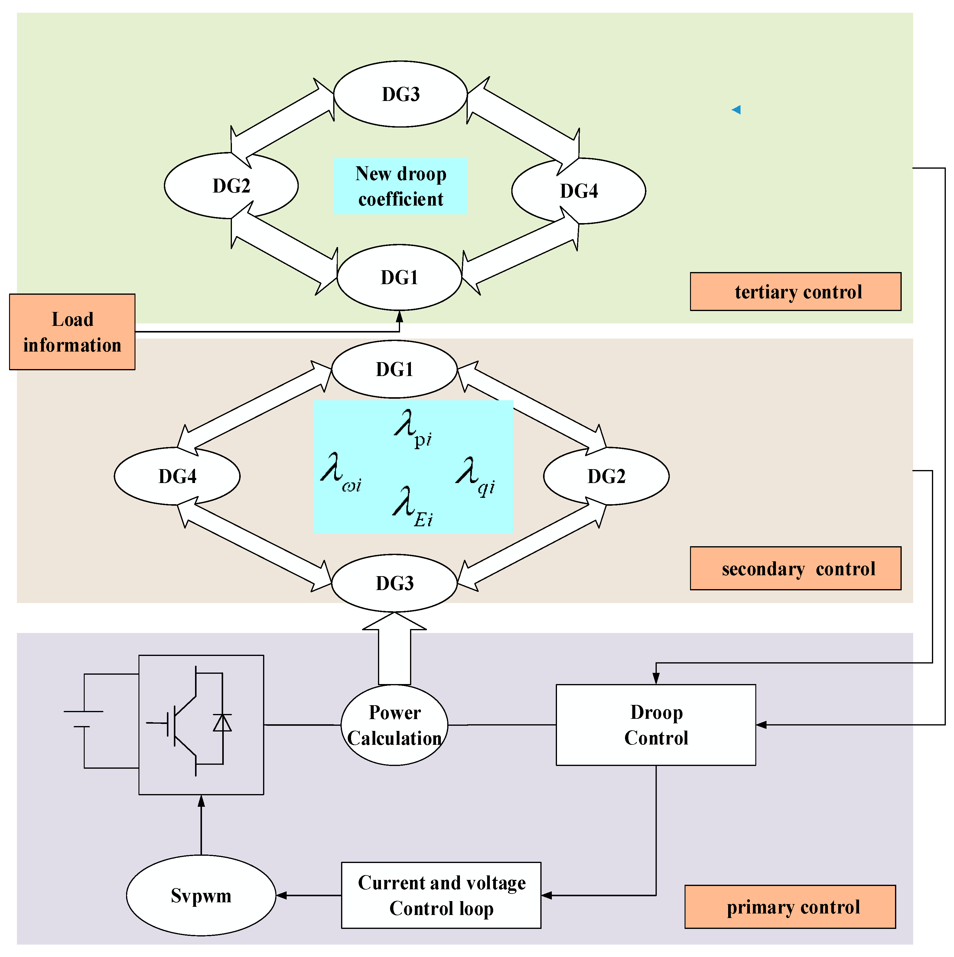
Traditional centralized control has been hard to meet the needs of microgrid systems with increasingly complex structures and large data volumes due to the increasing scale of microgrid. With the continuous development of multi-intelligent body systems, people start to use distributed control based on multi-intelligent body systems to solve problems that cannot be easily handled in centralized control, such as large data scale, many targets, and “plug-and-play”. In order to realize the overall control of microgrid, this paper proposes a hierarchical distributed control strategy based on the consensus algorithm of multi-intelligent body system with the premise of ensuring the reasonable output of each DG. The control structure is shown in Figure 1.
In order to coordinate the microgrid, the control strategy is divided into three layers. The primary control is the droop control, which regulates the output power of the inverter according to the droop curve. The second control is the deviation regulation layer. Firstly, the voltage and frequency compensation values are calculated by the leader-following consensus algorithm to maintain the stability of the voltage and frequency of the microgrid system, and then the power compensation values are calculated by the common consensus algorithm to realize the accurate power distribution according to the droop coefficient. The tertiary control is the dynamic power distribution layer, and the new droop coefficient is obtained by the leader-following consensus algorithm to make the adjustable power of DGs achieve consensus.
3.1. Primary Control
Droop control is to regulate the active and reactive power output of the inverter by changing the frequency and voltage of the inverter output by simulating the droop external characteristics of the synchronous generator. The control equation of droop control is shown in (2). Where , is the rated frequency and voltage of the inverter, , is the droop coefficient of active power and reactive power, , , , is the frequency, voltage, active power and reactive power output of the th inverter, respectively, and , are the rated active power and reactive power of the th inverter.
3.2. Deviation Control Based on Consensus Algorithm
- (1)
- Frequency—Active power
In the conventional droop control, it can be derived from Equation (2) that when the active power is not the rated value, it makes the frequency of the inverter deviate. Therefore, in the secondary control of the microgrid, the first control objective is to achieve frequency recovery. However, during the recovery of the frequency, since the compensation value of each DG will be different every time, which leads to differences in the transient frequency of each node. The differences can destroy the active power distribution achieved in the primary control based on the droop coefficient. In order to keep the original active power distribution constant, i.e., to keep Equation (3) valid, the second control target of secondary control, power distribution, is introduced.
In order to achieve both frequency recovery and active power distribution at the same time, the following control scheme is used. the secondary control equation of P-W is shown below
where is the variable reference frequency factor.
where is the frequency compensation factor and is the active power compensation factor.
Equation (6) not only achieves frequency consensus among different agents through the communication network, but also completes the tracking of the virtual leader frequency. Equation (7) is used to synchronize each DG by the agent consensus algorithm to compensate for the active power distribution mismatch caused by the different values of transient frequency compensation. Where is the communication weight factor, is the drafting gain, and when the node is the drafting point, , otherwise . is the reference frequency, , is a positive gain coefficient.
Where is the tracking error of the frequency
The matrix expression for the frequency tracking error is derived from (9)
of which , .
Theorem 1.
Graph G possesses a spanning tree and has at least one root node, i.e.,. Let. Whereis an element in vectorand satisfies, Let. It is possible to conclude thatis positive definite.
Consider the Lyapunov candidate function as
Derivation of :
Let
From Theorem 1, we know that is positive definite, and it follows that . Thus it can be obtained that , and finally the frequencies of all DGs will converge to the frequency reference value.
Defining active power tracking error
is the active power at steady state
Rewritten in matrix form
of which , .
Consider the Lyapunov candidate function as
Similarly, it can be proved that, let , can be obtained at the time of system stability, satisfying , i.e., the active power of the microgrid is distributed according to the droop factor.
- (2)
- Voltage—Reactive power
Because the line impedance mismatch will lead to a conflict between the voltage consensus of DG and the reactive power sharing of DG, it will prevent them from being achieved simultaneously. Furthermore, the use of virtual impedance can only weaken but not completely eliminate the deviation due to impedance. Therefore, transforming the inverter output voltage consensus originally controlled into controlling the inverter intermediate voltage consensus, where the intermediate voltage is defined as shown in (19), will be able to avoid such a conflict. Thus, transforming the control objective to achieve precise control of the voltage at the PCC and the accurate reactive power sharing.
To achieve these two control objectives a control scheme is designed as shown in (18):
In order to achieve precise control of the voltage at the PCC and equalization of reactive power, an intermediate voltage , which is represented as shown in (19), is chosen between the inverters. Where and are the intermediate voltage compensation factor and reactive power compensation factor, respectively. The intermediate voltage compensation factor is shown in (20)
where is a positive gain coefficient and is the reference value of the intermediate voltage, which is set so that the voltage at the PCC can be accurately recovered to the given reference value. The reference voltage is designed as shown in (21). Where is generally set as the rated voltage, and is the proportional and integral coefficients of the PI controller, respectively, and is the reference voltage at PCC. The difference between the reference value at PCC and the actual value is calculated by the PI controller and then summed with to generate the voltage reference value. When the output voltage of the inverter achieves tracking of the reference voltage under the control of the consensus algorithm, it can simultaneously achieve the tracking of the voltage at PCC to its reference voltage.
The reactive power compensation factor is shown in (22)
where is the positive gain coefficient and Equation (22) is mainly used to keep Equation (23) valid for accurate reactive power sharing.
Defining the voltage tracking error
Rewritten in matrix form
of which , .
Defining the reactive power tracking error
where is the reactive power at steady state
Rewritten in matrix form
of which , .
Similarly it can be shown that at system stability, and can hold, indicating that the intermediate voltage can be restored to the reference voltage and the reactive power can be distributed according to the reactive droop coefficient.
3.3. Power Control Based on Dynamic Adjustable Power Consensus
When the load suddenly increases, the maximum power of each DG is different, and the adjustable power is also different. If the power is not reasonably distributed, it may appear that some DGs have reached the maximum power output, while another DGs are working in a lower output state. In this case, on the one hand, it is impossible to respond to the load demand in time, on the other hand, the usage time and efficiency of the small-capacity DGs will also be affected, which may lead to the overuse of the DGs and cause unnecessary losses. Therefore, in the distributed control strategy proposed in this paper, the distributed algorithm is used to make the microgrid work at the optimum point according to the adjustable power of DG to respond to the change of the load when the load changes.
Let the maximum power of each DG be , defining the active power that can be adjusted by each DG be , can be derived:
The total active adjustable quantity can also be obtained as follows:
when the load increases , each DG increases its output , where it can be derived that
The response ratio of different DGs is defined as , whose expression is shown in (33), and is used to represent the ratio of the response of DGs to load changes and its adjustable active power.
when redistributing the active power, in order to let the DG with a large adjustable active power take as much of the load variation as possible, the response ratio of each DG has to be controlled to be consistent. This is so that the increased load will be distributed according to the adjustable active power of each DG. To achieve this control objective, a control scheme as shown in (34) is used.
where is a gain coefficient, is the leader of the response ratio, calculated by (35), and represents the ratio of the total load increase to the total adjustable active power.
Define the tracking error of the corresponding ratio
Rewritten in matrix form
of which , .
The proof process is similar to the above, and at steady state , i.e., the response ratio of each DG can be controlled to the reference response ratio.
After the new response ratio is calculated by the consensus algorithm, the active response power of each DG is calculated by (39), which is then summed with the previous output power to obtain the output power after the load increase, as shown in (40).
Finally the corrected droop coefficient can be calculated by (21), where c is a fixed constant
Similarly the corrected droop coefficient can be obtained
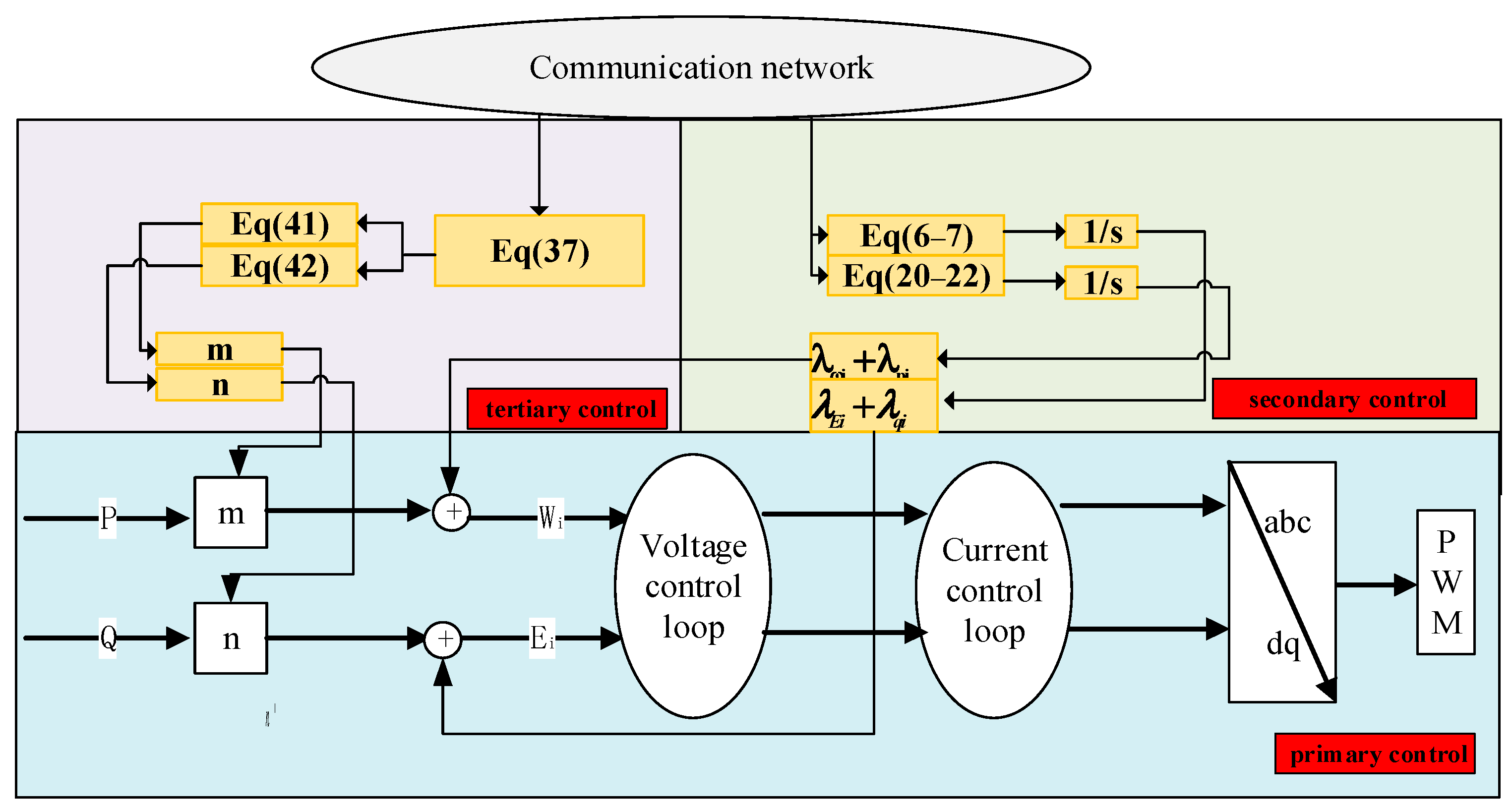
The new droop coefficient is sent to the primary control to achieve a reasonable distribution of power. The hierarchical control structure is shown in Figure 2.
4. Simulation Analysis
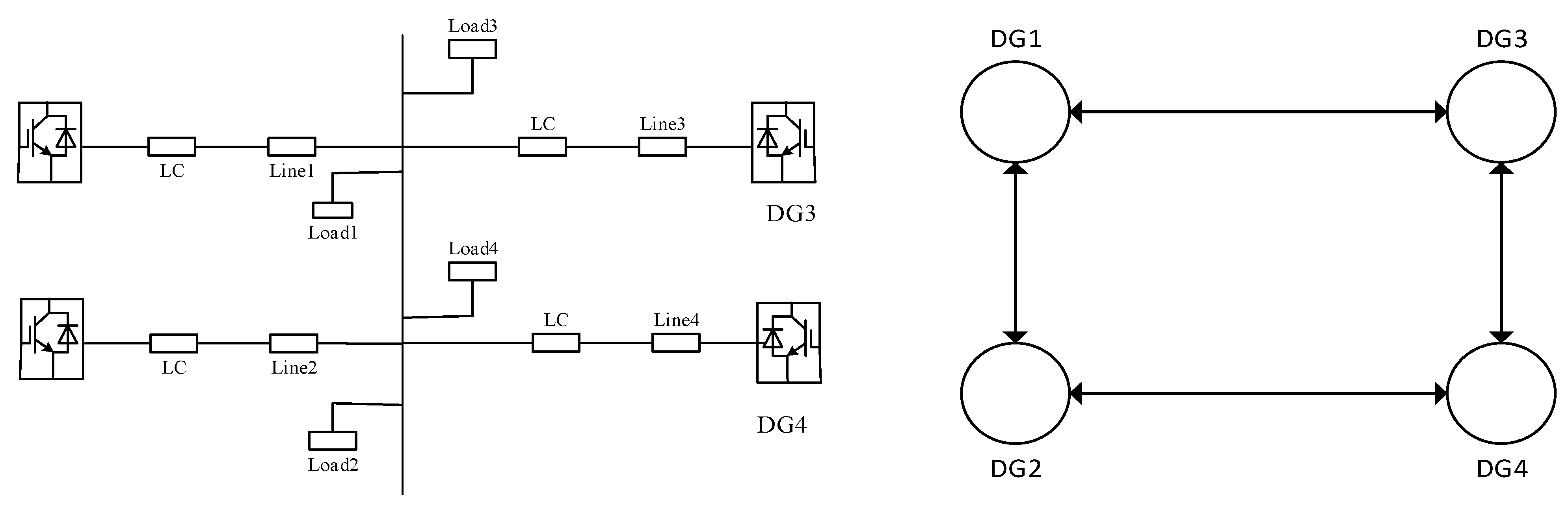
To verify the effectiveness of the proposed hierarchical distributed control, the simulation model is built on MATLAB/Simulink simulation platform. The framework of the microgrid is shown in Figure 3, four DGs are used, the communication in DG is shown in Figure 3, the rated voltage of the system is 380 V and the frequency is 50 Hz, the parameters of DG capacity, load and line impedance are shown in Table 1.
First, the first and second layers of the system are verified to see if the recovery of system frequency and voltage can be achieved. At 0 s the system starts with load and the rated power ratio of DG is DG1:DG2:DG3:DG4 = 3:4:4:3 and the initial load of the system is 28 KW + j28 KVar, at 0.5 s the load is increased by 14 KW + j14 KVar.
Figure 4a shows that at the start of the system, there is an initial drop in frequency due to starting with load, but it is able to recover to 50 Hz and remain stable in about 0.2 s with the effect of the consistent frequency compensation factor. The voltage at PCC and the intermediate voltage of the system are shown in Figure 4b,c, respectively. In the voltage control, the intermediate voltage is introduced to achieve the voltage recovery at PCC and the accurate distribution of reactive power at the same time, and the convergence process of the intermediate voltage can be seen from Figure 4c. At 0.5 s, due to the sudden increase of the load. The reference value of the intermediate voltage will increase under the affect of the PI controller. Under the effect of consensus, the intermediate voltage of the four DGs track the reference voltage, and finally bring the voltage at the PCC back to the standard value.
The simulation set the power distribution ratio to DG1:DG2:DG3:DG4 = 3:4:4:3. From Figure 5a,b we can see that the active power distributed by each DG is 6 KW, 8 KW, 8 KW, 6 KW respectively, and the reactive power is the same. The load increases at 0.5 s and the same accurate distribution of active and reactive power are achieved. Figure 5c shows the mp consensus achieved with the introduction of the active power compensation factor, where a sudden increase in load at 0.5 s causes the mp to increase and reach a new steady state value. Figure 5d shows the nq consensus of reactive power with the same transformation process as active power.
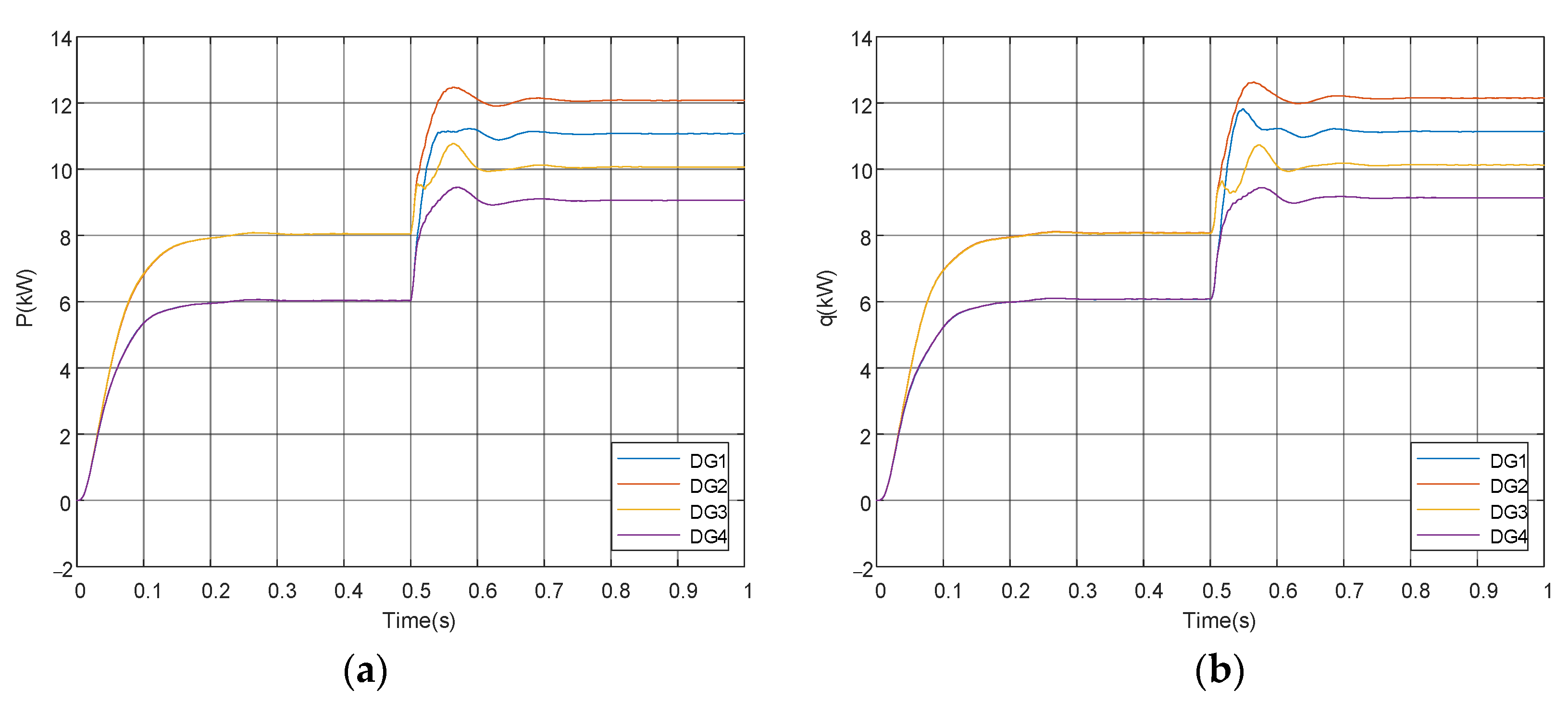
The system is then verified after adding the tertiary layer of control, which is mainly designed to respond to load changes and distribute the increased load by the response ratio when the load increases.
Figure 6 shows that the system is running steadily before 0.5 s and the active power allocated by DG1-4 are 6 KW 8 KW, 8 KW, 6 KW respectively. At 0.5 s the system increases load 14 KW + j14 kvar. At this time setting, the maximum output power is DG1-4 to16 kw, 16 KW, 12 KW, 12 KW, so at this time, the more adjustable power of DG1 should bear an increased load, and the less adjustable power of DG3 should bear less of an increased load. The response ratio is calculated to allocate the increased load, and the response of DG1-4 to the increased load is 5 KW, 4 KW, 2 KW, 3 KW respectively, and the final power allocated by DG1-4 should be 11 KW, 12 KW, 10 KW, 9 KW. Figure 6b shows the change process of reactive power, which is the same as the change process of active power.
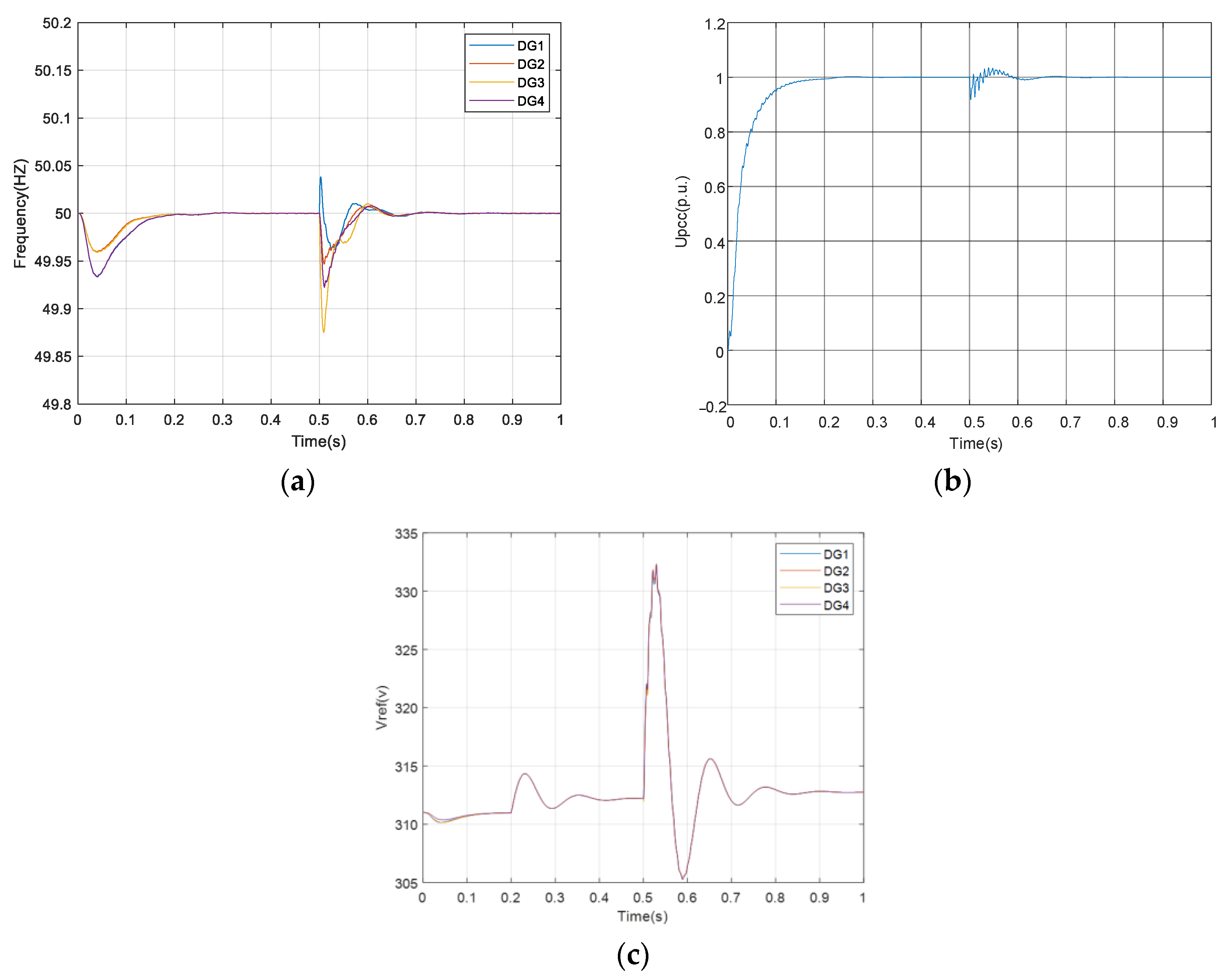
Figure 7a,b show the variation process of the frequency and the voltage at PCC after the system is added to the tertiary control. Frequency and voltage are both stable after a brief oscillation. Figure 7c shows the course of the intermediate voltage.
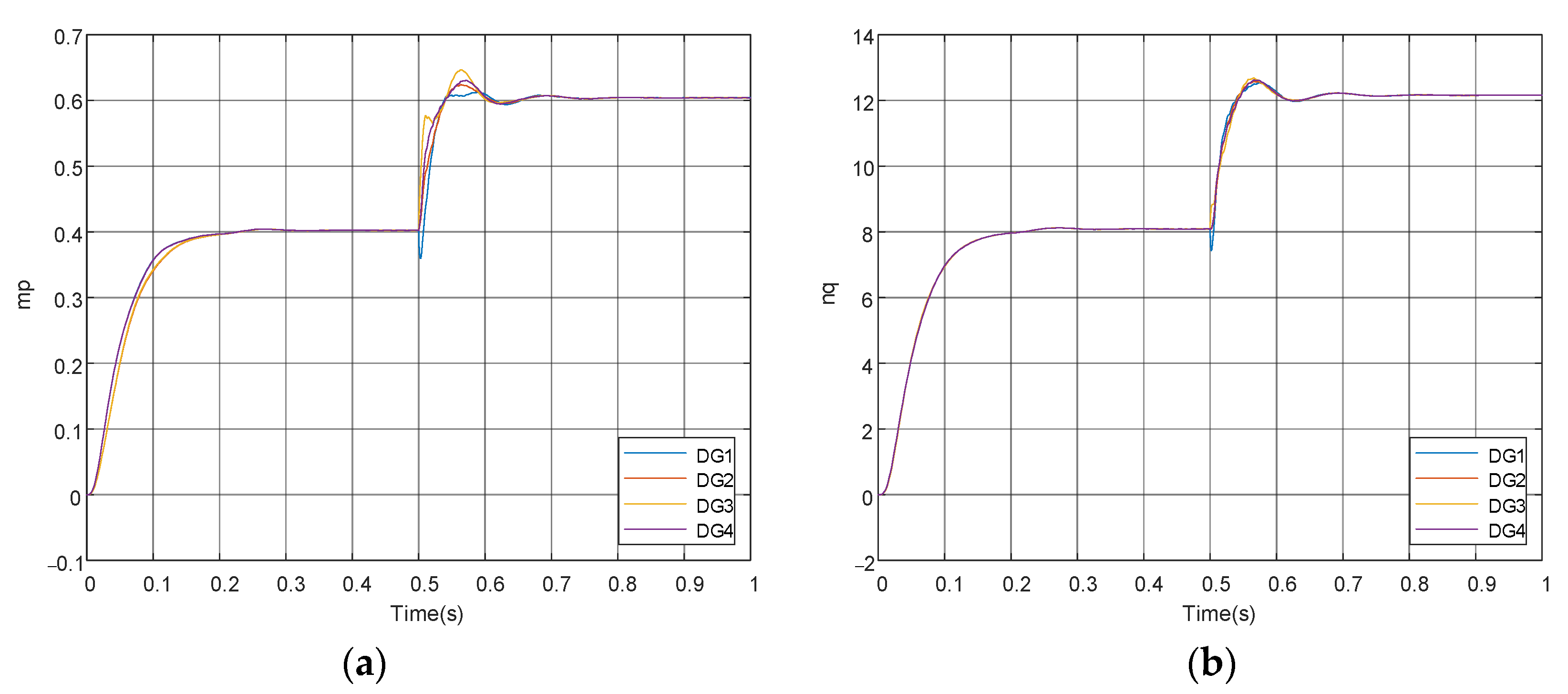
Figure 8a,b show how mp and nq reach consensus in tertiary control.
5. Conclusions
A hierarchical control strategy for microgrid based on adjustable power consensus is proposed by this paper by using distributed cooperative control. The conflict between voltage recovery and reactive power distribution due to line impedance mismatch is solved by using intermediate voltage in the secondary control. Compared with the traditional hierarchical control, the proposed hierarchical control strategy dynamically responds to the load by adjusting the adjustable power in real time in the tertiary control, and it not only recovers the frequency and voltage at PCC, but also ensures the accurate control of active and reactive power in the process of dynamic response and finally realizes the reasonable operation of the microgrid. The proposed control strategy is verified in MATLAB/Simulink simulation platform, and all agents are able to work in coordination to achieve control objectives.
Hierarchical control needs the support from communication networks and communication delay is an unavoidable problem in signal transmission process. Communication delay can impair the dynamic performance of the system, reduce the system stability margin, and even result in an unstable system. Therefore, the delay compensation method can be further studied. Additionally, considering the event triggering mechanism to further reduce the communication of the system is also the subsequent work of this paper.
Author Contributions
Conceptualization, X.W. and J.W.; methodology, J.W.; software, J.W.; validation, X.W. and J.W.; formal analysis, J.W.; investigation, J.W.; resources, X.W.; data curation, J.W.; writing—original draft preparation, J.W.; writing—review and editing, X.W.; visualization, X.W.; supervision, X.W.; project administration, X.W.; funding acquisition, X.W. All authors have read and agreed to the published version of the manuscript.
Funding
This research was funded by National Natural Science Foundation of China, grant number 51867017.
Data Availability Statement
The data that support the findings of this study are included within the article.
Conflicts of Interest
The authors declare no conflict of interest.
References
- Abbott, D. Keeping the Energy Debate Clean: How Do We Supply the World’s Energy Needs? Proc. IEEE 2009, 98, 42–66. [Google Scholar] [CrossRef]
- Moslehi, K.; Kumar, R. A Reliability Perspective of the Smart Grid. IEEE Trans. Smart Grid 2010, 1, 57–64. [Google Scholar] [CrossRef]
- Nejabatkhah, F.; Li, Y.W. Overview of Power Management Strategies of Hybrid AC/DC Microgrid. IEEE Trans. Power Electron. 2015, 30, 7072–7089. [Google Scholar] [CrossRef]
- Patrao, I.; Figueres, E.; Garcerá, G. Microgrid architectures for low voltage distributed generation. Renew. Sust. Energ. Rev. 2015, 43, 415–424. [Google Scholar] [CrossRef]
- Sahoo, S.K.; Sinha, A.K.; Kishore, N.K. Control Techniques in AC, DC, and Hybrid AC-DC Microgrid: A Review. IEEE J. Emerg. Sel. Top. Power 2017, 6, 738–759. [Google Scholar] [CrossRef]
- Tsikalakis, A.G.; Hatziargyriou, N.D. Centralized Control for Optimizing Microgrids Operation. IEEE Trans. Energy Convers. 2008, 23, 241–248. [Google Scholar] [CrossRef]
- Guerrero, J.M.; Chandorkar, M.; Lee, T.L. Advanced Control Architectures for Intelligent MicroGrids, Part I: Decentralized and Hierarchical ControlAdvanced Control Architectures for Intelligent Microgrids. IEEE Trans. Ind. Electron. 2013, 60, 1254–1262. [Google Scholar] [CrossRef] [Green Version]
- Guerrero, J.M.; Vasquez, J.C.; Matas, J. Hierarchical Control of Droop-Controlled AC and DC Microgrids—A General Approach Toward Standardization. IEEE Trans. Ind. Electron. 2011, 58, 158–172. [Google Scholar] [CrossRef]
- Li, Y.W.; Kao, C.N. An Accurate Power Control Strategy for Power-Electronics-Interfaced Distributed Generation Units Operating in a Low-Voltage Multibus Microgrid. IEEE Trans. Ind. Electron. 2009, 24, 2977–2988. [Google Scholar]
- Lopes, J.; Moreira, C.L.; Madureira, A.G. Defining Control Strategies for MicroGrids Islanded Operation. IEEE Trans. Power Syst. 2006, 21, 916–924. [Google Scholar] [CrossRef] [Green Version]
- Simpson-Porco, J.W.; Dorfler, F.; Bullo, F. Stability, power sharing, & distributed secondary control in droop-controlled microgrids. In Proceedings of the IEEE International Conference on Smart Grid Communications (SmartGridComm), Vancouver, BC, Canada, 21 October 2013; pp. 672–677. [Google Scholar]
- Hashmi, K.; Mansoor Khan, M.; Jiang, H.; Umair Shahid, M.; Habib, S.; Talib Faiz, M.; Tang, H. A Virtual Micro-Islanding-Based Control Paradigm for Renewable Microgrids. Electronics 2018, 7, 105. [Google Scholar] [CrossRef] [Green Version]
- Han, H.; Hua, X.C.; Yang, J. Review of Power Sharing Control Strategies for Islanding Operation of AC Microgrids. IEEE Trans. Smart Grid 2016, 7, 200–215. [Google Scholar] [CrossRef] [Green Version]
- Lv, Z.; Zhou, M.; Wang, Q.; Hu, W. Small-Signal Stability Analysis for Multi-Terminal LVDC Distribution Network Based on Distributed Secondary Control Strategy. Electronics 2021, 10, 1575. [Google Scholar] [CrossRef]
- Guo, F.H.; Wen, C.Y.; Mao, J.F. Distributed Cooperative Secondary Control for Voltage Unbalance Compensation in an Islanded Microgrid. IEEE Trans. Ind. Inform. 2015, 11, 1078–1088. [Google Scholar] [CrossRef]
- Simpson-Porco, J.W.; Shafiee, Q.; Dorfler, F. Secondary Frequency and Voltage Control of Islanded Microgrids via Distributed Averaging. IEEE Trans. Ind. Electron. 2015, 62, 7025–7038. [Google Scholar] [CrossRef]
- Zhang, H.G.; Kim, S.; Sun, Q.Y. Distributed Adaptive Virtual Impedance Control for Accurate Reactive Power Sharing Based on Consensus Control in Microgrid. IEEE Trans. Smart Grid 2017, 8, 1749–1761. [Google Scholar] [CrossRef]
- Liu, J.Y.; Li, J.Q.; Song, H.H. Nonlinear Secondary Voltage Control of Islanded Microgrid via Distributed Consistency. IEEE Trans. Energy Convers. 2020, 35, 1964–1972. [Google Scholar] [CrossRef]
- Garcia-Torres, F.; Vazquez, S.; Moreno-Garcia, I.M.; Gil-de-Castro, A.; Roncero-Sanchez, P.; Moreno-Munoz, A. Microgrids Power Quality Enhancement Using Model Predictive Control. Electronics 2021, 10, 328. [Google Scholar] [CrossRef]
- Lou, G.N.; Gu, W.; Wang, J.H. Optimal Design for Distributed Secondary Voltage Control in Islanded Microgrids: Communication Topology and Controller. IEEE Trans. Power Syst. 2019, 34, 968–981. [Google Scholar] [CrossRef]
- Wang, P.; Wang, D.; Zhu, C. Stochastic management of hybrid AC/DC microgrids considering electric vehicles charging demands. Energy Rep. 2020, 6, 1338–1352. [Google Scholar] [CrossRef]
- Mohamed, M.A.; Abdullah, H.M.; El-Meligy, M.A. A novel fuzzy cloud stochastic framework for energy management of renewable microgrids based on maximum deployment of electric vehicles. Int. J. Electr. Power Energy Syst. 2021, 129, 106845. [Google Scholar] [CrossRef]
- Zou, H.B.; Tao, J.; Elsayed, S.K.; Elattar, E.E. Stochastic multi-carrier energy management in the smart islands using reinforcement learning and unscented transform. Int. J. Electr. Power Energy Syst. 2021, 130, 106988. [Google Scholar] [CrossRef]
- Lan, T.; Liu, X.; Wang, S.; Jermsittiparsert, K.; Alrashood, S.T.; Rezaei, M.; Al-Ghussain, L.; Mohamed, M.A. An Advanced Machine Learning Based Energy Management of Renewable Microgrids Considering Hybrid Electric Vehicles’ Charging Demand. Energies 2021, 14, 569. [Google Scholar] [CrossRef]
- Mohamed, M.A.; Tao, J.; Su, W.C. Multi-agent energy management of smart islands using primal-dual method of multipliers. Energy 2020, 208, 118306. [Google Scholar] [CrossRef]
- Nguyen, T.L.; Wang, Y.; Tran, Q.T. A distributed hierarchical control framework in islanded microgrids and its agent-based design for cyber-physical implementations. IEEE Trans. Ind. Electron. 2021, 68, 9685–9695. [Google Scholar] [CrossRef]
- Liu, Y.; Li, Y.Z.; Wang, Y.; Zhu, J.Z. Distributed real-time multi-objective control of a virtual power plant in dc distribution systems. IEEE Trans. Power Deliv. 2021; early access. [Google Scholar] [CrossRef]
Figure 1.
Microgrid system control structure diagram.

Figure 2.
Block diagram of hierarchical control structure.

Figure 3.
Microgrid architecture and communication topology diagram.

Figure 4.
(a) Frequency waveform, (b) voltage waveform at PCC, (c) intermediate voltage waveform.

Figure 5.
(a) Active power waveform; (b) reactive power waveform; (c) active power consensus; (d) reactive power consensus.
Figure 5.
(a) Active power waveform; (b) reactive power waveform; (c) active power consensus; (d) reactive power consensus.

Figure 6.
After adding tertiary control: (a) active power waveform; (b) reactive power waveform.

Figure 7.
After adding tertiary control: (a) frequency waveform, (b) voltage waveform at PCC, (c) intermediate voltage waveform.
Figure 7.
After adding tertiary control: (a) frequency waveform, (b) voltage waveform at PCC, (c) intermediate voltage waveform.

Figure 8.
After adding tertiary control: (a) active power consensus; (b) reactive power consensus.


Table 1.
Microgrid system parameters.
| DG s | DG 1 | DG 2 | DG 3 | DG 4 |
|---|---|---|---|---|
| M (rad/W) | 6.67 × 10⁻⁵ | 5 × 10⁻⁵ | 6.67 × 10⁻⁵ | 5 × 10⁻⁵ |
| N (V/Var) | 1.33 × 10⁻³ | 1 × 10⁻³ | 1.33 × 10⁻³ | 1 × 10⁻³ |
| Rline (Ω) | 0.015 | 0.01 | 0.02 | 0.013 |
| Lline (mH) | 0.013 | 0.27 | 0.16 | 0.25 |
| Pload (KW) | 10 | 5 | 7 | 6 |
| Qload (KVar) | 8 | 7 | 6 | 7 |
Publisher’s Note: MDPI stays neutral with regard to jurisdictional claims in published maps and institutional affiliations. |
© 2022 by the authors. Licensee MDPI, Basel, Switzerland. This article is an open access article distributed under the terms and conditions of the Creative Commons Attribution (CC BY) license (https://creativecommons.org/licenses/by/4.0/).
Share and Cite
MDPI and ACS Style
Wan, X.; Wu, J. Distributed Hierarchical Control for Islanded Microgrids Based on Adjustable Power Consensus. Electronics 2022, 11, 324. https://0-doi-org.brum.beds.ac.uk/10.3390/electronics11030324
AMA Style
Wan X, Wu J. Distributed Hierarchical Control for Islanded Microgrids Based on Adjustable Power Consensus. Electronics. 2022; 11(3):324. https://0-doi-org.brum.beds.ac.uk/10.3390/electronics11030324
Chicago/Turabian StyleWan, Xiaofeng, and Jingwan Wu. 2022. "Distributed Hierarchical Control for Islanded Microgrids Based on Adjustable Power Consensus" Electronics 11, no. 3: 324. https://0-doi-org.brum.beds.ac.uk/10.3390/electronics11030324
Note that from the first issue of 2016, this journal uses article numbers instead of page numbers. See further details here.