1. Introduction
The so called “Space Age” began with the launch of the Russian satellite Sputnik, on 1 October 1957. Afterwards, space activity grew exponentially in a showdown between Russia and United States, reaching a peak with the Apollo program. The enthusiastic rush to the space, however, initially neglected the possible congestion of the space environment due to the space operations discards, namely the orbital space debris. Space debris is comprised of manmade objects, with variable sizes and shapes, orbiting around Earth, including satellite fragments, rocket stages, and other objects related to human space activities that have stopped their functions [
1,
2,
3]. The problem represented by the space debris is double: the presence of these objects is an obstacle for manned and unmanned spacecraft maneuvers, increasing the risk of possible collisions and—in this eventuality—allowing the creation of even new debris, in a chain reaction better known as Kessler syndrome [
4]. So, it is quite clear that, in order to avoid possible threats from these objects, a set of suitable countermeasures is needed. Nowadays, two main solutions are available to mitigate the space debris problem: collision avoidance [
5] and shielding. For relatively large objects (≥10 cm), the preferred solution is collision avoidance, whereas for smaller objects (<1 cm) the application of shields onto the spacecraft bodies is widely used. Actually, there is a third solution: active debris removal from the space environment, which has remarkably improved in the last years [
2,
6] but it is still in its early stages.
Collision avoidance is the sum of those countermeasures that allow evasion of impacts between spacecraft and debris. Such a solution is possible thanks to space debris detection and identification by means of radio or optical telescope measurements. In particular, some bistatic configurations, including modern high performance radio telescopes, can detect, and even track, space debris with high accuracy and reliability. Space Debris measurements include space-based and ground-based measurements. Ground-based measurements fall into two categories: radar measurements and optical measurements. Radar measurements have been typically used to detect space debris in Low Earth Orbit (LEO) between 200 and 2000 km [
7]. The reason is because, compared with the optical measurements, they grant a 24-hour a day observation with very high sensitivity and they are not tied to meteorological conditions.
Radio telescopes are mainly conceived for radio astronomy observations. They have a high gain (and directivity): therefore, they have a limited field of view. For this reason, they are not suitable to be used as transmitting antennas for space debris observation since the transmitting antenna should provide a relatively wide illumination of the sky. Moreover, due to the high sensitivity of radio astronomy receivers, in order to avoid interferences and serious damage of all the radio astronomy instrumentation, it is not possible to transmit high power with these kind of antennas. The above considerations lead to the use of a bistatic radar configuration for space debris observation, which employs:
- (a)
an antenna transmitting high power, typically with a relatively wide beam, used to illuminate the space debris;
- (b)
a large radio telescope with high sensitivity and precise pointing, which acts as the receiving antenna and is used to detect and, possibly, track debris.
Until now, in Europe, there are around 50 different radio telescopes. In the space debris detection plan, the European Space Agency collaborates primarily with the operators of the Tracking and Imaging Radar (TIRA) system, located near Bonn, in Germany. In its monostatic configuration, the TIRA is able to detect objects of diameters down to 2 cm at 1000 km, but in a bistatic configuration, in synergy with the Effelsberg Radio Telescope of the Max Planck Institute for Radio Astronomy, the system can detect objects down to 1 cm diameter [
8,
9]. The Effelsberg Radio Telescope is one of the largest radio telescopes in Europe used as a receiver, with its 100-m dish. The 64-m dish Sardinia Radio Telescope (SRT) is a newcomer in the debris detection plan, but thanks to its high sensitivity and efficiency (up to 60 % from 0.3 to 15 GHz), it could be one of the best receiver radio telescopes for bistatic space debris monitoring. Actually, the speed movement of the SRT is 0.85°/s in azimuth and 0.5°/s in elevation, almost double that of the Effelsberg Radio Telescope’s performance. This feature can be useful for fast re-positioning during an observation or in the tracking mode. Moreover, the smaller dimension of SRT, compared to the Effelsberg 100-m dish, means a larger beam and Field Of View. Therefore, the SRT versatility is a good trade-off between precision and detection ability.
Among worldwide radio telescopes used for space debris monitoring, with his 64-m dish, the SRT is one of the largest provided with an active surface system [
10]. In the back side of the primary reflector, a total of 1116 electro-mechanic actuators are installed, with each one acting on a single panel. These actuators can compensate for every possible deformation of the dish either due to gravitational effects, thermal gradients, or even wind.
The space debris monitoring is part of the Italian Institute for Astrophysics (INAF)—Cagliari Astronomical Observatory research activity in the framework convention ASI/INAF n. 2015-028-R.O, named “Space Debris—IADC activities support and SST pre-operative validation”. In this framework, the INAF participation concerns the testing of the SRT’s operative capacities in the detection of signals scattered by space debris.
In this paper, the authors present a set of measures for LEO detection of space debris, performed with a bistatic radar configuration, named BIRALET (BIstatic RAdar for LEo Tracking), using a 4 kW Continuous Wave (CW) signal in the P band (410 MHz), generated by the military facility named Flight Terminator System (FTS), and received by the SRT. The list of the debris to detect, their Radar Cross Section (RCS), and the time window of the observation were provided by Italian Air Force. A preliminary study was conducted to evaluate the azimuth and elevation pointing coordinates of the SRT. The experimental results show that all debris on the list has been successfully detected and the Doppler shift has been measured.
2. Bistatic Radar for LEO Tracking
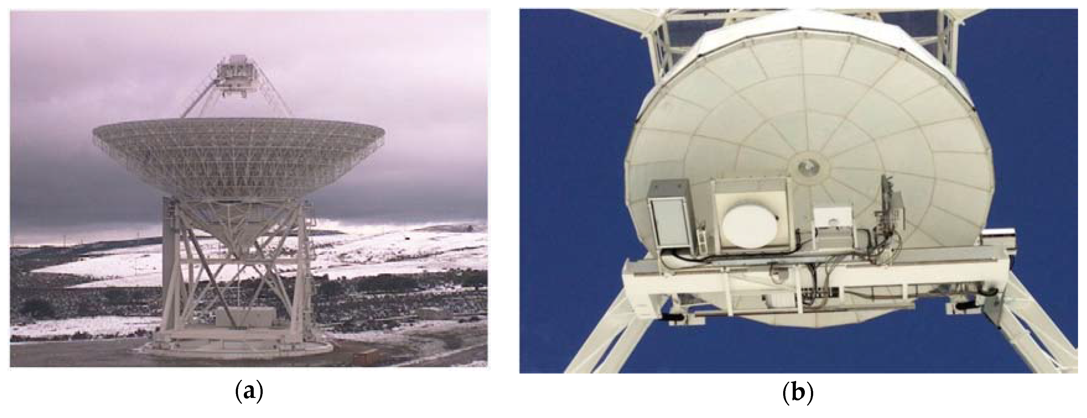
The BIRALET radar configuration employed in this work for space debris detection is a bistatic one, thus the transmitter and receiver antennas are separated. In particular, the transmitter is represented by the FTS of the Italian Joint Test Range located in the region “Salto di Quirra”, and the receiver is represented by the SRT located 35 km north of Cagliari at Lat. 39.49307238896°—Long. 9.2451512445321° (
Figure 1). The baseline of the bistatic system is about 40 km. The FTS, owned by Italian Air Force, is provided with a 4 kW power supply amplifier in the 400–455 MHz bandwidth [
11]. The transducers used by the FTS are an omnidirectional antenna and a wide beam directional antenna [
12]. The transmitter is usually employed in CW mode and, consequently, this prevents the measurement of the object range. The receiver is the 64-mt dish of SRT, a fully steerable wheel-and-track parabolic antenna. In full operational mode, the SRT is able to host up to 20 remotely controllable receivers and to observe the sky with high efficiency in the frequency range between 0.3–116 GHz [
13]. In order to observe the signal sent from FTS and scattered by the debris, the coaxial dual-feed L-P band (0.305–0.410 GHz, 1.3–1.8 GHz) cryogenic receiver of SRT has been used (
Figure 1) [
14,
15,
16,
17].
The features of the transmitter and receiver antennas at 410 MHz are reported in
Table 1. In
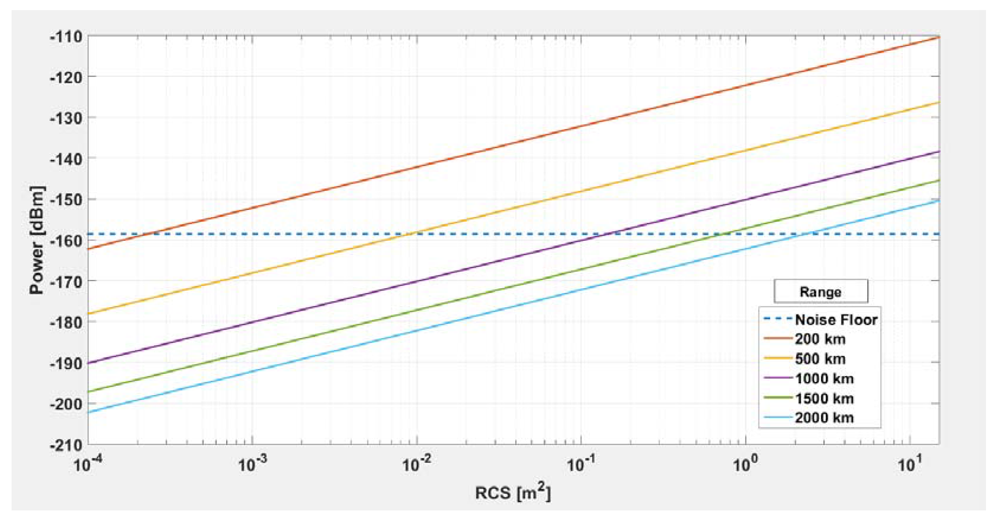
Figure 2, the RCS of the objects detectable with the BIRALET radar is estimated based on the data of
Table 1, for different values of the object range in LEO (from 200 Km to 2000 Km). In particular, we will be able to detect an object when the back-scattered power at the receiver antenna is greater than the noise floor
NF
wherein
Kb is the Boltzmann constant;
TSYS is the system temperature—i.e., the sum
TA and
TR—which are respectively the antenna temperature and the P-band receiver noise temperature (see
Table 1); and
BN is the resolution bandwidth of the spectrum analyzer, set to 200 Hz for our observation.
As shown in
Figure 2, the BIRALET system in its actual configuration (P
T = 4 KW transmitted power) is expected to be able to detect objects with RCS larger than 5 cm
2 at a range of 200 km, with RCS larger than 0.3 m
2 at a range of 1000 km, and with RCS larger than 4 m
2 at a range of 2000 km.
3. Results
In order to show the ability of the SRT, to effectively detect and identify the space debris, a brief forecasting campaign has been carried out. The list of the debris to be detected, their RCS and the time window of the observation (i.e., the FTS turn-on and turn-off times) were provided by the Italian Air Force to ensure a good spread in terms of RCS. This list is reported in
Table 2.
For each debris of the list, the pointing coordinates of the receiving antenna (in azimuth and elevation) must be predicted with high accuracy, since the SRT half power beamwidth at 410 MHz is 0.8 degrees (
Table 1).
The azimuth and elevation pointing angles of the SRT were obtained by using a Python script, which is summarized as follows:
- (1)
The Two-Line Element sets (TLEs) (downloaded the day of the observation) of an object (satellite or debris) are propagated with the Simplified General Perturbation model 4 (SGP4) [
11] up to the UTC time (hh:mm:ss) at the moment of the observation.
- (2)
The script takes the latitude, longitude, and altitude of the SRT , and the UTC observation date (in the format year/month/day, hh:mm:ss) as input data;
- (3)
The script computes the position of the object (azimuth and elevation) with respect to the location of the observer (the azimuth and elevation angles are computed in terms of degrees, arcminutes, and arcseconds with an overall precision up to the third decimal place, which fits well with the SRT pointing precision of 0.002 degrees).
The above algorithm is also designed to allow a sequential pointing useful for both detection and for tracking scenarios.
The resulting azimuth and elevation coordinates of the SRT for the list of the selected debris are shown in
Table 3.
During the detection campaign, on 17 April, 2014, a sinusoidal signal (CW) of about 4 KW at 410 MHz has been transmitted by the FTS to the identified debris and observed by the SRT in beam park mode, using the primary focus L-P receiver, according to the pointing angles reported in
Table 3. The session objective for SRT was the target detection by means of the signal-to-noise ratio (SNR), acquisition time, and radar Doppler frequency;
The backend used during the session was the Agilent A4446E spectrum analyzer with the following setup:
Moreover, for all tests (except for the detection of VESSELSAT 2), an amplifier with 25 dB gain was added to the measurement set-up, setting the attenuation of the spectrum analyzer equal to 10 dB, for a total gain value of 15 dB. The list of the debris is the same as in
Table 2 and
Table 3.
Table 4 shows the name (and passage) of the debris, the duration of the received echoes (visibility interval), the Doppler shift, and the SNR, computed as:
wherein DPP is the Debris Peak Power, i.e., the power measured by the spectrum analyzer for a debris at the center of its visibility interval (
Table 4). The SNR values reported in
Table 4 are basically consistent with the RCS and range values reported in
Table 2: the SNR is proportional to the RCS and inversely proportional to the range, according to the radar equation. However, a precise relation between the data reported in
Table 2 and the measured SNR is not achievable since the reported RCS is a mean value, which does not take into account the debris tumbling, its shape, and its orientation with respect to the bistatic radar.
In
Figure 3,
Figure 4,
Figure 5,
Figure 6,
Figure 7,
Figure 8,
Figure 9 and
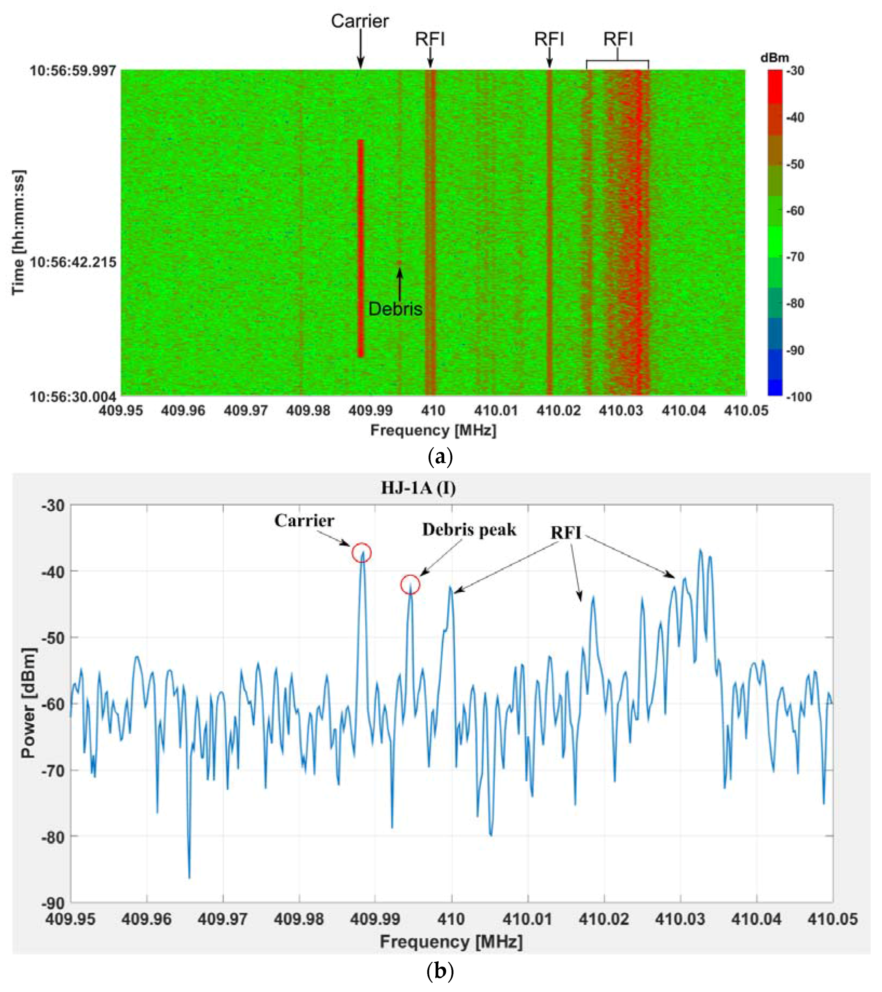
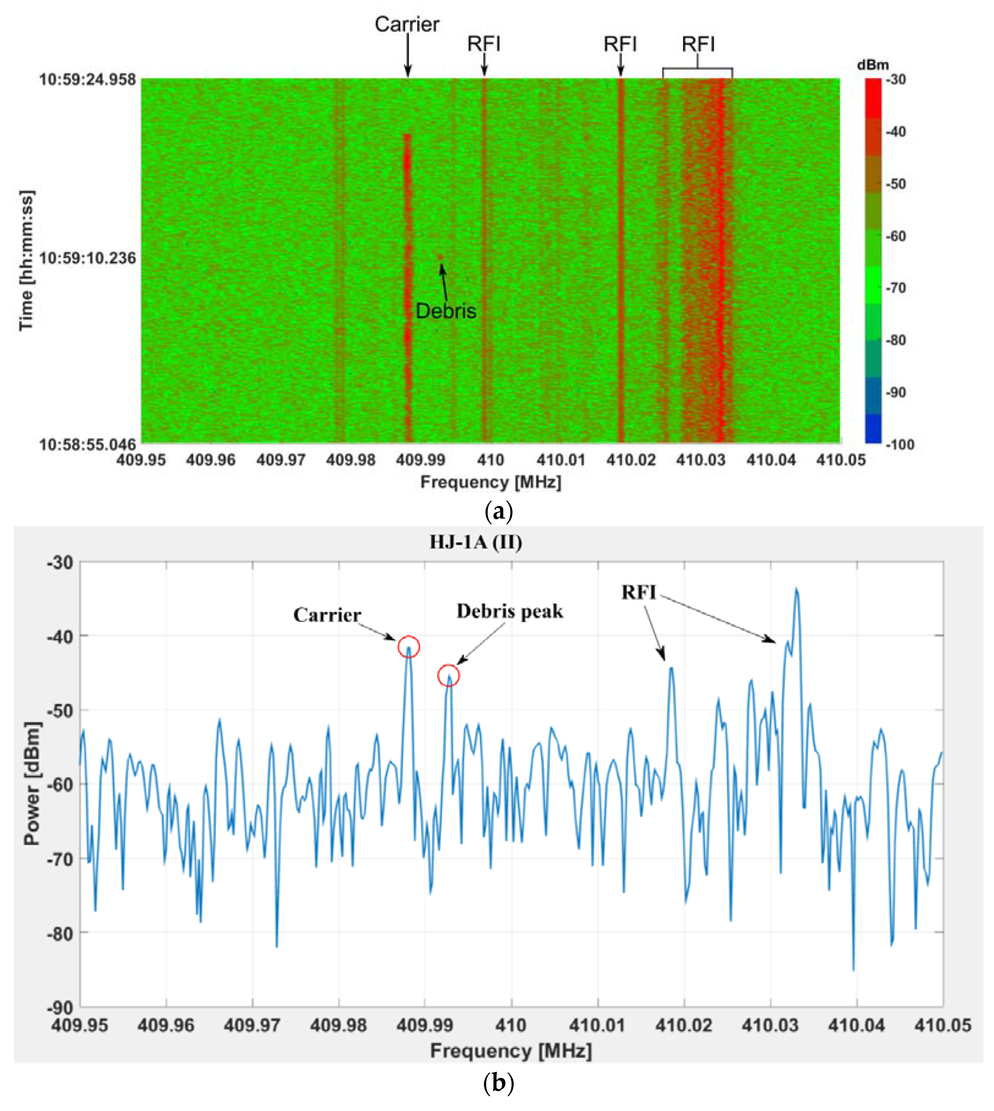
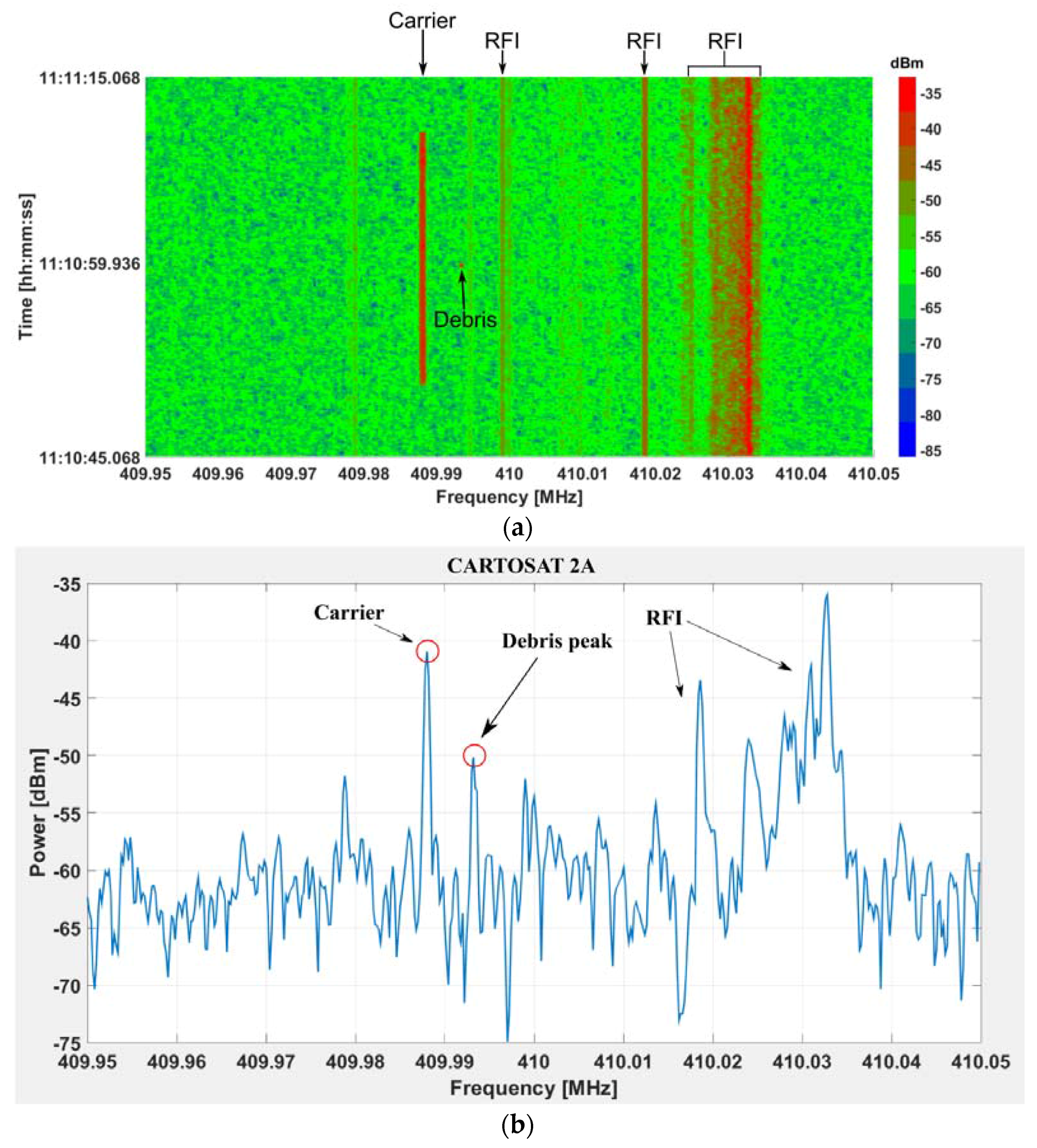
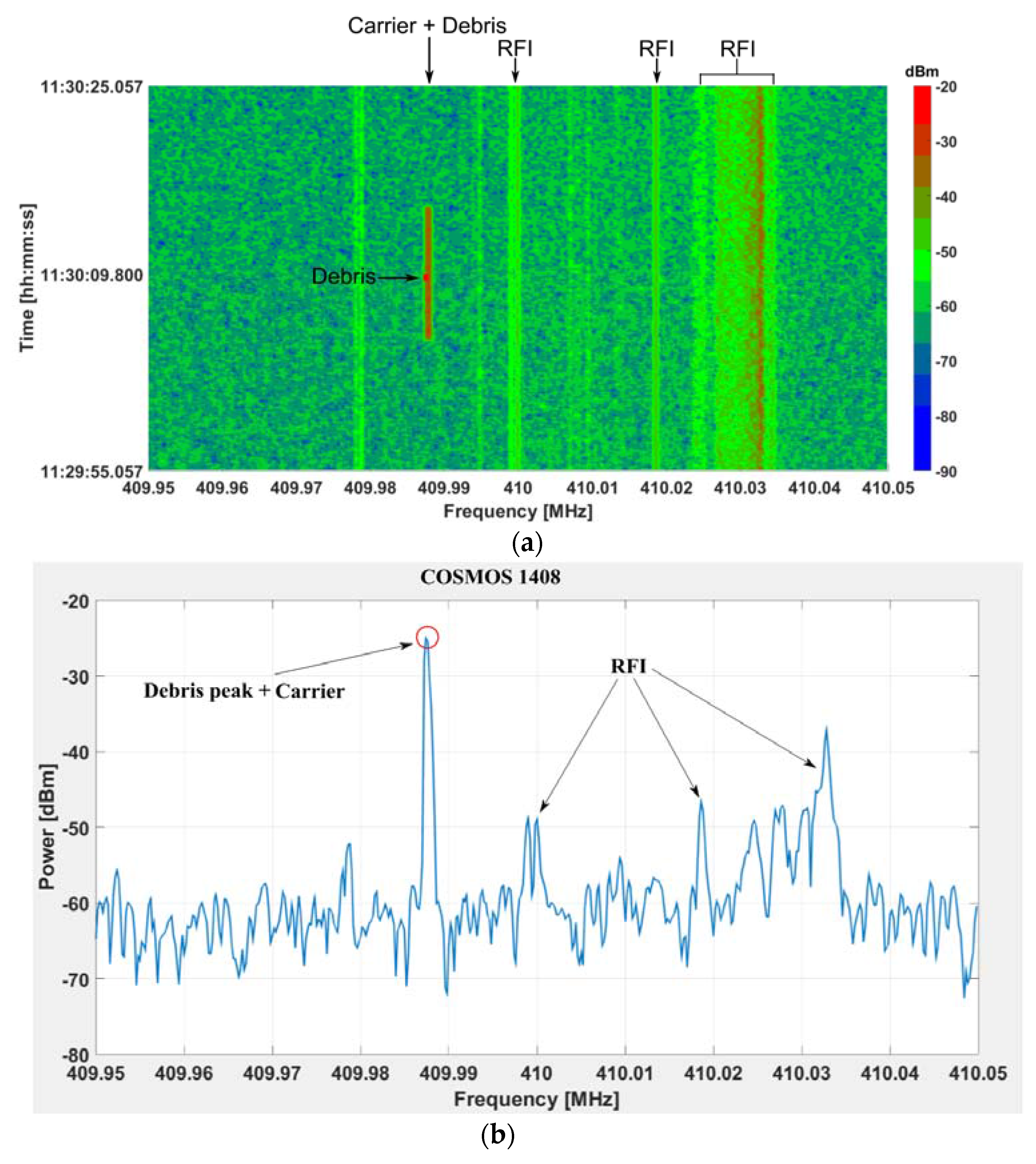
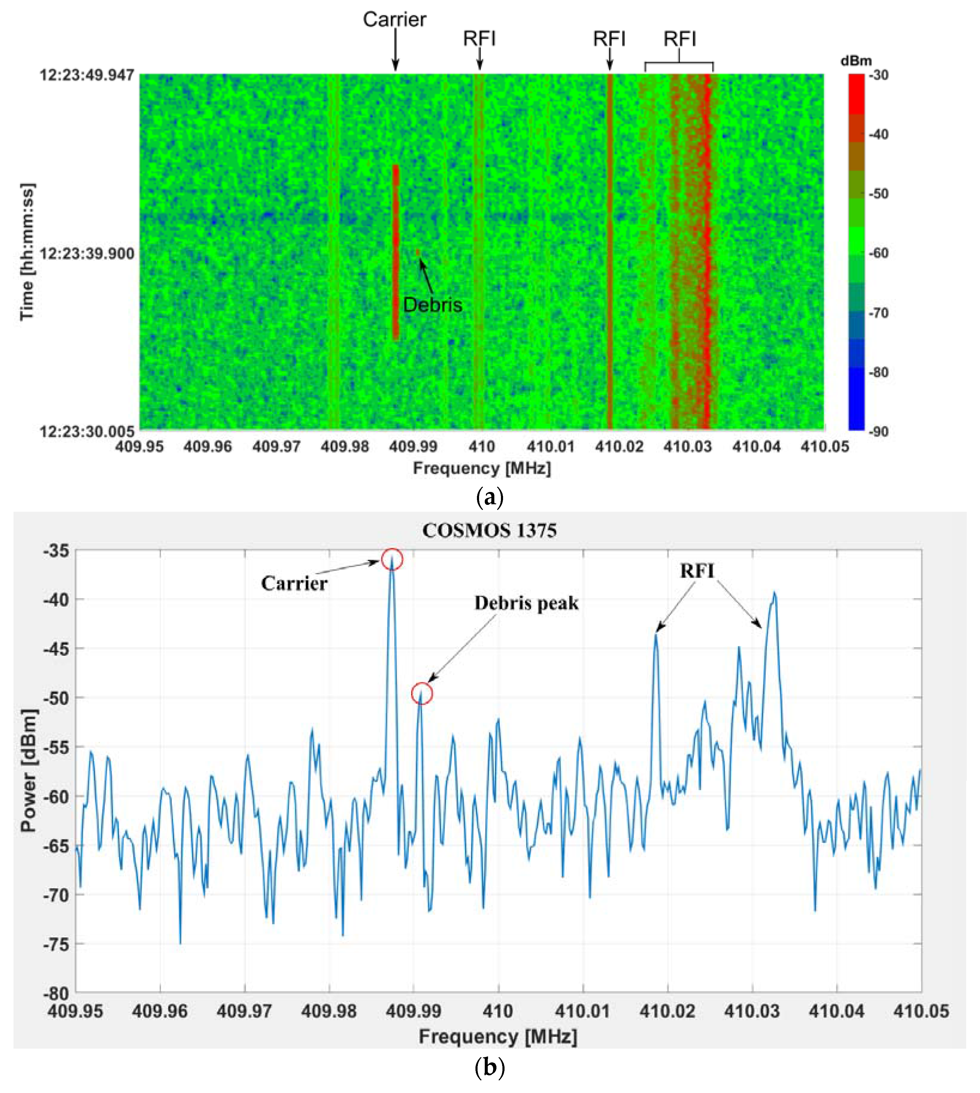
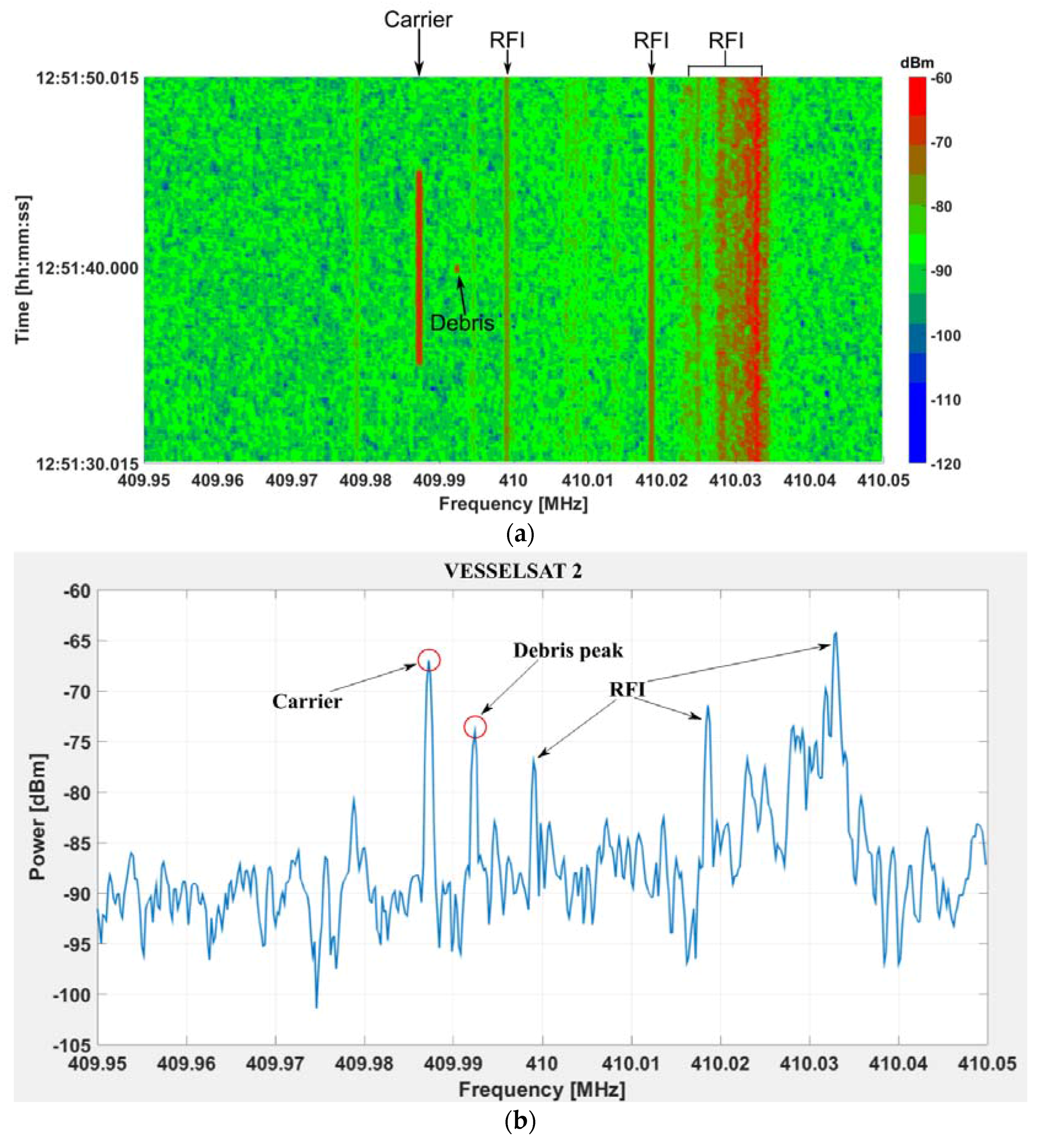
Figure 10, for each debris, the spectrogram along the observation time window and the screenshot of the spectrum analyzer at the center of the visibility interval (
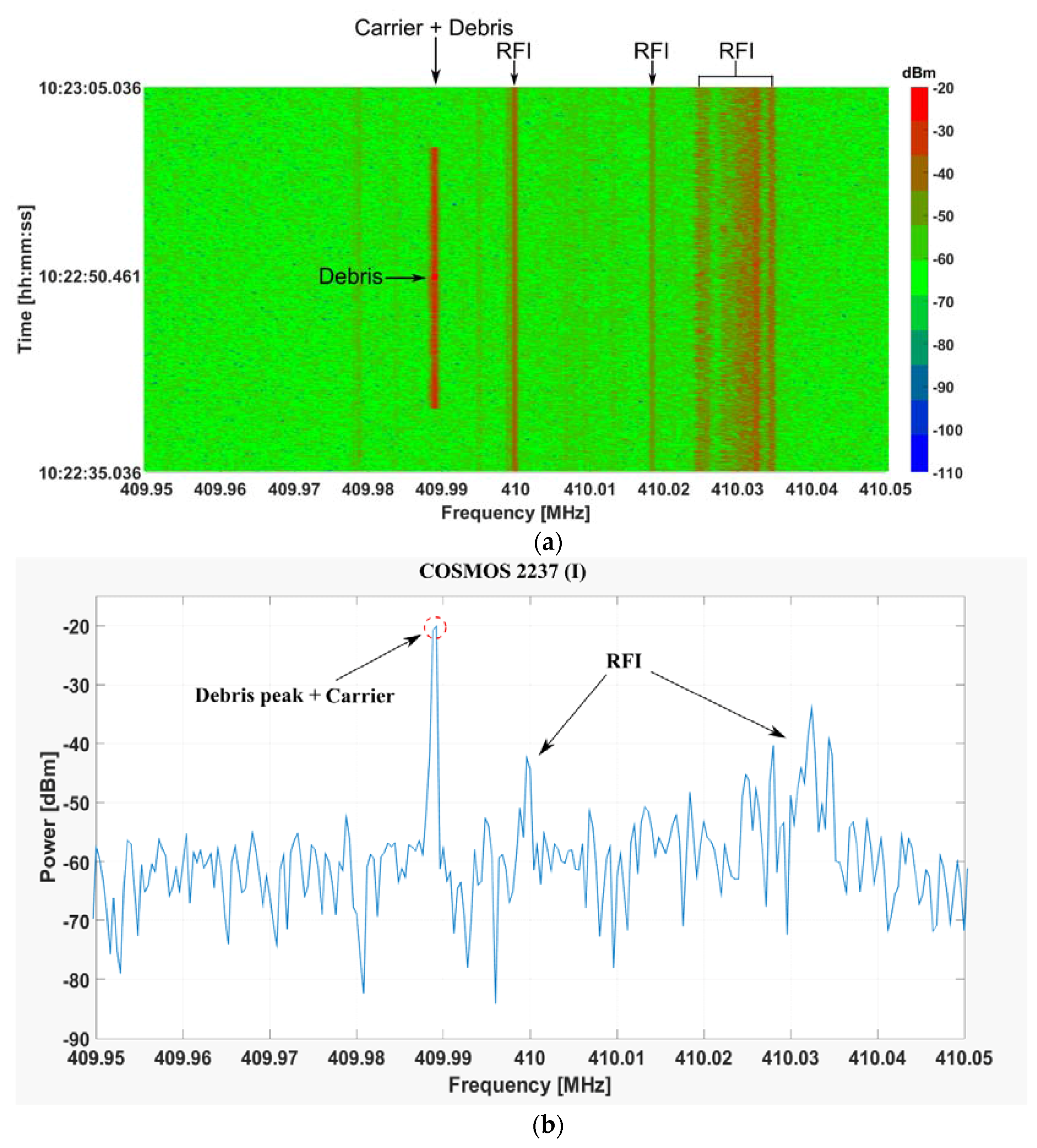
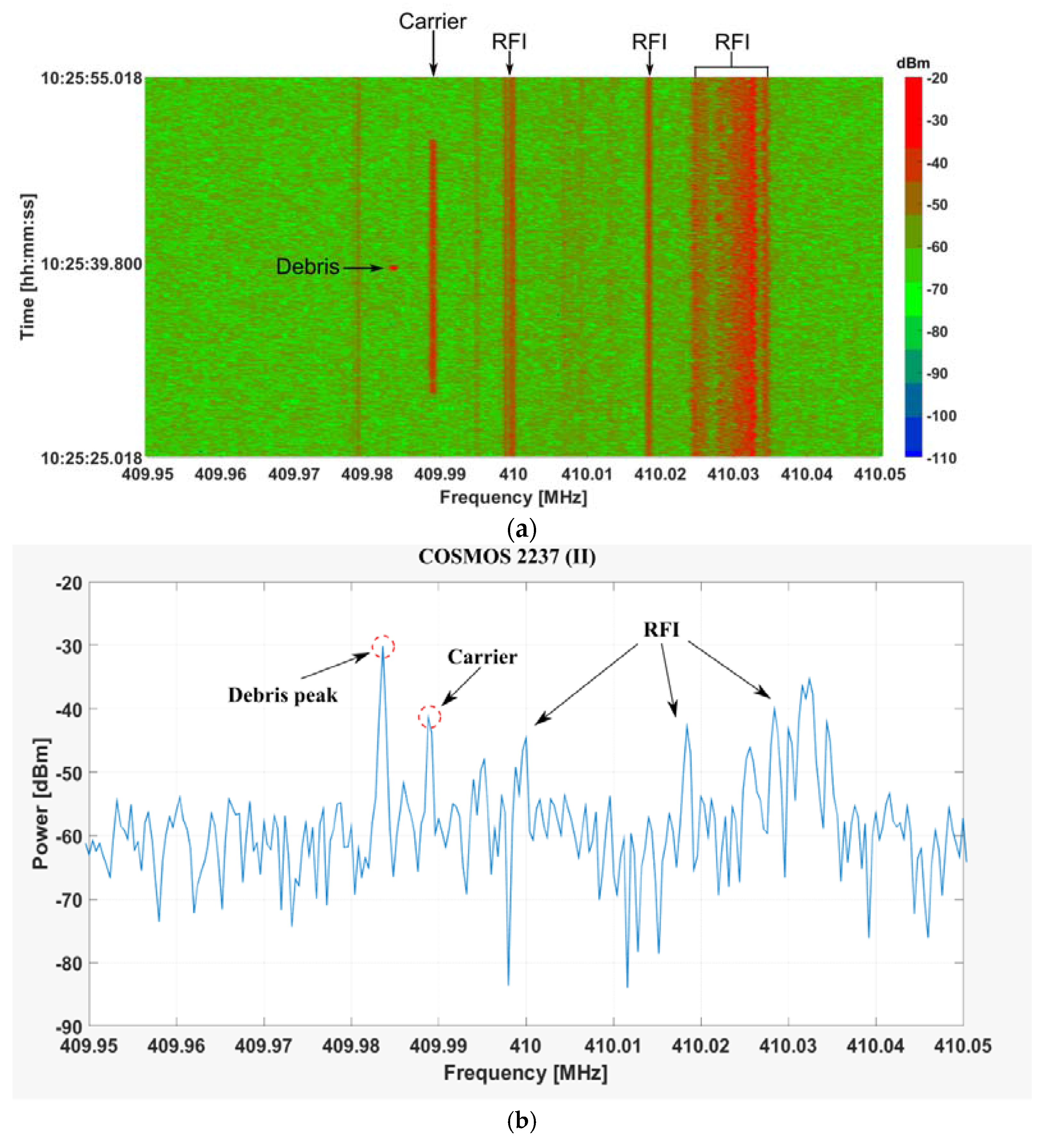
Table 4) are shown. The spectrogram is a two dimensional plot which shows the level of the received power at the back-end as a function of frequency and time.
The Doppler shift reported in
Table 3 has been computed by the difference between the carrier frequency and the echo from the debris (as clearly visible in the screenshots reported in
Figure 3b,
Figure 4b,
Figure 5b,
Figure 6b,
Figure 7b,
Figure 8b,
Figure 9b and
Figure 10b). Due to the proximity of the receiver and transmitter antennas in our scenario, we were able to receive the carrier frequency, which is clearly visible in all the spectrograms as the signal detected throughout the observation window (i.e., from the start time and the stop time in
Table 2). From the above results, it is clear that every debris on the list was successfully detected, though in two cases (COSMOS 2237 in
Figure 3, COSMOS1408 in
Figure 8) the Doppler shift was not detected since it was smaller than the resolution bandwidth used in the spectrum analyzer (the peak of the carrier virtually overlaps with the echo from the debris).
It should be noted that, during the measurement campaign, part of the bandwidth was occupied by Radio Frequency Interferences (RFIs), which are clearly visible in the spectrograms of
Figure 3,
Figure 4,
Figure 5,
Figure 6,
Figure 7,
Figure 8,
Figure 9 and
Figure 10 as continuous lines. These RFIs are related to the Terrestrial Trunked Radio (TETRA) assigned to the Italian Ministry of Defense. The authors were aware of the exact frequency of the RFIs, but an automatic system to mitigate these effects is not yet available for the SRT, though it is planned in the near future.
4. Conclusions and Future Work
In this work, a measurement campaign to detect space debris in LEO has been performed using a bistatic radar named BIRALET, including the FTS military facility as the transmitter, and the Sardinia Radio Telescope as the receiver. A preliminary analysis to obtain the azimuth and elevation pointing coordinates of SRT was conducted. The spectrograms of the received echoes of the space debris are reported, showing the level of the power received by SRT. The duration of the echoes, the Doppler frequency shift and the signal-to-noise ratio for each debris are also shown. During the campaign on 17 April, 2014, every debris within the list provided by the Italian Air Force was successfully detected, proving that the high efficiency and sensitivity of SRT, combined with its fast azimuth and elevation speed movement, make this radio telescope an excellent candidate as a receiver for space debris monitoring and tracking.
In its actual configuration, the BIRALET system can be employed to compute the direction and Doppler shift. However, in order to improve the orbit knowledge, the range would also be required. In the near future, the research group of the Cagliari Astronomical Observatory would upgrade the BIRALET with two major improvements. The first one aims to provide the measurement of the range of the detected debris. From this perspective, we are planning to build an entirely new transmitter antenna capable of sending a mixed signal, partly CW to obtain the Doppler shift, and partly pulsed (about 20% of the whole signal) to obtain the range. The second improvement concerns the installation of a new kind of receiver on the SRT, a Phased Array Feed (PAF), operating at higher frequencies, most likely in the C band (5.85–8.20 GHz) or in the X band (8.20–12.4 GHz). The PAF will be used to illuminate a bigger area in the sky, using multiple beams. In this way, the SRT will be able to draw a map of the debris position, as well as follow and track it. Another advantage, resulting from the installation of a PAF, is that we could perform a space debris survey in confined sky regions (e.g., the near space around an important satellite).

 ,
, 


